

Page 1

Inside…
Installation Instructions
Electromechanical Relay Contact Output
Module
Cat. No. 1771-OW16 Series B
To : See Page:
Important User Information 1
Preinstallation Considerations 5
Calculate Power Requirements 6
Key the Backplane Connector 7
Install the Module and Field Wiring Arm 7
Important User Information
Connect Wiring to the Field Wiring Arm 8
Interpret the Status Indicators 11
Specifications 12
Rockwell Automation Support BackCover
Solid state equipment has operational characteristics differing from those of
electromechanical equipment. Safety Guidelines for the Application,
Installation and Maintenance of Solid State Controls (Publication SGI-1.1
available from your local Rockwell Automation sales office or online at
http://www.rockwellautomation.com/literature) describes some important
differences between solid state equipment and hard-wired electromechanical
devices. Because of this difference, and also because of the wide variety of
uses for solid state equipment, all persons responsible for applying this
equipment must satisfy themselves that each intended application of this
equipment is acceptable.
In no event will Rockwell Automation, Inc. be responsible or liable for
indirect or consequential damages resulting from the use or application of
this equipment.
The examples and diagrams in this manual are included solely for illustrative
purposes. Because of the many variables and requirements associated with
any particular installation, Rockwell Automation, Inc. cannot assume
responsibility or liability for actual use based on the examples and diagrams.
No patent liability is assumed by Rockwell Automation, Inc. with respect to
use of information, circuits, equipment, or software described in this manual.
Reproduction of the contents of this manual, in whole or in part, without
written permission of Rockwell Automation, Inc., is prohibited.
1 Publication 1771-IN069B-EN-P - November 2005
Page 2
2 Electromechanical Relay Contact Output Module
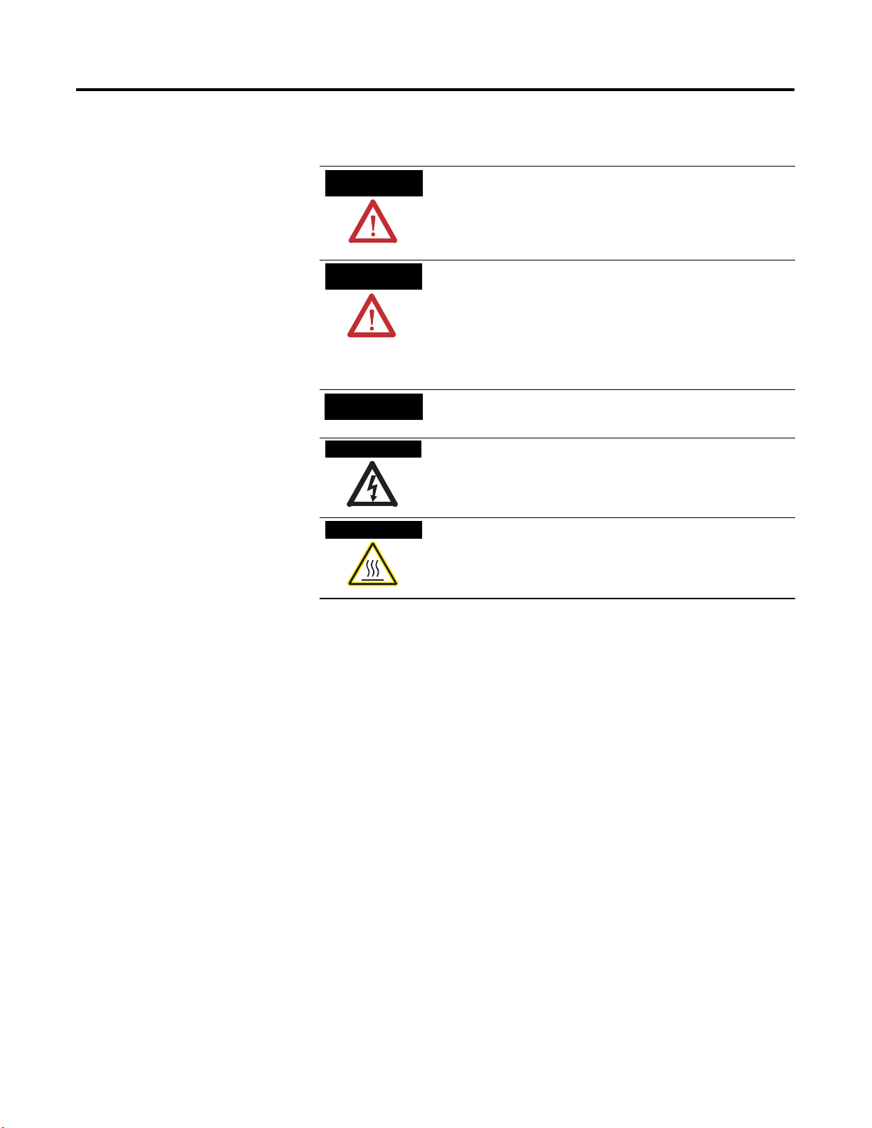
Throughout this manual we use notes to make you aware of safety
considerations.
WARNING
Identifies information about practices or circumstances
that can cause an explosion in a hazardous environment,
which may lead to personal injury or death, property
damage, or economic loss.
ATTENTION
IMPORTANT
SHOCK HAZARD
BURN HAZARD
Identifies information about practices or circumstances
that can lead to personal injury or death, property damage,
or economic loss. Attentions help you:
• identify a hazard
• avoid a hazard
• recognize the consequence
Identifies information that is critical for successful
application and understanding of the product.
Labels may be located on or inside the equipment (e.g.,
drive or motor) to alert people that dangerous voltage may
be present.
Labels may be located on or inside the equipment (e.g.,
drive or motor) to alert people that surfaces may be
dangerous temperatures.
Publication 1771-IN069B-EN-P - November 2005
Page 3
Electromechanical Relay Contact Output Module 3
ATTENTION
Environment and Enclosure
This equipment is intended for use in a Pollution Degree 2
industrial environment, in overvoltage Category II
applications (as defined in IEC publication 60664-1), at
altitudes up to 2000 meters without derating.
This equipment is considered Group 1, Class A industrial
equipment according to IEC/CISPR Publication 11.
Without appropriate precautions, there may be potential
difficulties ensuring electromagnetic compatibility in other
environments due to conducted as well as radiated
disturbance.
This equipment is supplied as “open type” equipment. It
must be mounted within an enclosure that is suitably
designed for those specific environmental conditions that
will be present and appropriately designed to prevent
personal injury resulting from accessibility to live parts.
The interior of the enclosure must be accessible only by
the use of a tool. Subsequent sections of this publication
may contain additional information regarding specific
enclosure type ratings that are required to comply with
certain product safety certifications.
See NEMA Standards publication 250 and IEC
publication 60529, as applicable, for explanations of the
degrees of protection provided by different types of
enclosure. Also, see the appropriate sections in this
publication, as well as the Allen-Bradley publication
1770-4.1 (Industrial Automation Wiring and Grounding
Guidelines), for additional installation requirements
pertaining to this equipment.
ATTENTION
Preventing Electrostatic Discharge
This equipment is sensitive to electrostatic discharge, which
can cause internal damage and affect normal operation.
Follow these guidelines when you handle this equipment:
• Touch a grounded object to discharge potential static.
• Wear an approved grounding wriststrap.
• Do not touch connectors or pins on component
boards.
• Do not touch circuit components inside the equipment.
• If available, use a static-safe workstation.
• When not in use, store the equipment in appropriate
static-safe packaging.
Publication 1771-IN069B-EN-P - November 2005
Page 4
4 Electromechanical Relay Contact Output Module
T
WARNING
When you connect or disconnect the wiring arm with field
side power applied, an electrical arc can occur. This could
cause an explosion in hazardous location installations.
Be sure that power is removed or the area is nonhazrdous
before proceeding.
WARNING
If you connect or disconnect wiring while field side power
is applied, an electrical arc can occur. This could cause an
explosion in hazardous location installations.
Be sure that power is removed or the area is nonhazrdous
before proceeding.
North American Hazardous Location Approval
The following information applies when
operating this equipment in hazardous locations:
Products marked “CL I, DIV 2, GP A, B, C, D” are
suitable for use in Class I Division 2 Groups A, B, C, D,
Hazardous Locations and nonhazardous locations only.
Each product is supplied with markings on the rating
nameplate indicating the hazardous location
temperature code. When combining products within a
system, the most adverse temperature code (lowest
“T” number) may be used to help determine the overall
temperature code of the system. Combinations of
equipment in your system are subject to investigation
by the local Authority Having Jurisdiction at the time
of installation.
WARNING
EXPLOSION HAZARD
•Do not disconnect
equipment unless power has
been removed or the area is
known to be nonhazardous.
•Do not disconnect
connections to this equipment
unless power has been
removed or the area is known
to be nonhazardous. Secure
any external connections that
mate to this equipment by
using screws, sliding latches,
threaded connectors, or other
means provided with this
product.
•Substitution of components
may impair suitability for
Class I, Division 2.
•If this product contains
batteries, they must only be
changed in an area known to
be nonhazardous.
Informations sur l’utilisation de cet équipement en
environnements dangereux :
Les produits marqués "CL I, DIV 2, GP A, B, C, D" ne
conviennent qu’à une utilisation en environnements de
Classe I Division 2 Groupes A, B, C, D dangereux et non
dangereux. Chaque produit est livré avec des marquages
sur sa plaque d’identification qui indiquent le code de
température pour les environnements dangereux. Lorsque
plusieurs produits sont combinés dans un système, le
code de température le plus défavorable (code de
température le plus faible) peut être utilisé pour
déterminer le code de température global du système. Les
combinaisons d’équipements dans le système sont
sujettes à inspection par les autorités locales qualifiées
au moment de l’installation.
AVERTISSEMEN
RISQUE D’EXPLOSION
•Couper le courant ou s’assurer
que l’environnement est classé
non dangereux avant de
débrancher l'équipement.
•Couper le courant ou s'assurer
que l’environnement est classé
non dangereux avant de
débrancher les connecteurs.
Fixer tous les connecteurs
externes reliés à cet
équipement à l'aide de vis,
loquets coulissants,
connecteurs filetés ou autres
moyens fournis avec ce produit.
•La substitution de composants
peut rendre cet équipement
inadapté à une utilisation en
environnement de Classe I,
Division 2.
•S’assurer que l’environnement
est classé non dangereux avant
de changer les piles.
Publication 1771-IN069B-EN-P - November 2005
Page 5

Electromechanical Relay Contact Output Module 5
Preinstallation Considerations
This module must be used with a 1771-A1B through 1771-A4B or later
chassis. It may also be used in a 1771-AM1 or 1771-AM2 chassis. This module
does not contain surge limiting circuitry. With properly chosen surge limiting
devices, this module can be used to control resistive, capacitive, and inductive
loads.
The module’s outputs are arranged in two groups of eight, each output is
independently isolated. The first group of outputs are arranged as
normally-open contacts, and the second group of outputs are arranged as
selectable normally-open or normally-closed contacts.
Refer to Specifications on page 12 for complete output specifications.Relay
Reliability
Varying load conditions can drastically shorten relay life. Operation at the
same load conditions, preferably at low loads, delivers long relay life. Do not
operate relays at low current or voltage after operating them at high power
conditions. Operations at low power first, followed by high power, is
acceptable.
Relay Environment
Relays in this module are not hermetically sealed. Do not use this module in
environments with contaminants such as acid, ammonia, nitrogen, and
chlorine.
Module Loading
Both minimum current and minimum voltage specifications are given to assure
there is always a good conduction surface between the relay’s contacts. The
relays will function at less than minimum specified voltages and currents, but
module reliability is not guaranteed.
Exceeding the module’s maximum power ratings wil shorten the life of the
relay contacts. Do not operate this module with voltage, current, or power
levels higher than the maximum specifications, as given in the Specifications
section of this installation instruction.
Publication 1771-IN069B-EN-P - November 2005
Page 6

6 Electromechanical Relay Contact Output Module
Load Characteristics
Inductive or high current loads cause arcing of the relay contacts, resulting in
shortened contact life. Use a resistor-capacitor network (RC) across the
contacts to suppress arcing. Failure to use an RC filter network could result in
generation of electromagnetic noise (EMI) which can disrupt nearby electrical
equipment, including your 1771 I/O chassis. Connect the RC filter across the
contacts at the field wiring arm connections. If this is not possible, an alternate
(but not as effective) solution would be to place the RC network across the
load.
Calculate Power Requirements
ATTENTION
Wirewound resistors do have some inductance associated
with them and may require an RC Filter network.
Allen-Bradley Suppressors
Allen-Bradley Equipment Suppressor Catalog Number
Motor Starter Bulletin 509 599-KD4
Motor Starter Bulletin 709
Relay Bulletin 700 Type N or P 700N5/700N9
Miscellaneous
1
For starters with 120V ac coils.
2
Bulletin 700-N24 is a universal surge suppressor. You can use it on electromagnetic devices with the limitation of
35 sealed VA, 150V.
1401-N10
700-N24
1
2
The module receives its power through the 1771 I/O chassis backplane from
the chassis power supply. This supply also provides the necessary power to
energize the coils of the module’s relays. The maximum current required from
this supply with all coils energized is 1.3 A.
Publication 1771-IN069B-EN-P - November 2005
Add this current to the requirements of all other modules in the I/O chassis to
prevent overloading the chassis backplane and/or backplane power supply.
Page 7

Electromechanical Relay Contact Output Module 7
Key the Backplane Connector
ATTENTION
Observe the following precautions
when inserting or removing keys:
• insert or remove keys with
your fingers
• make sure that key placement
is correct
Incorrect keying or the use of a tool
can result in damage to the backplane
connector and possible system faults.
Place your module in any slot in the chassis except the leftmost slot which is
reserved for processors or adapters.
Position keying bands in the backplane connectors to
correspond to the key slots on the module.
I/O Chassis
Upper Connector
You can change the position of these bands if subsequent system
design and rewiring makes insertion of a different type of module
necessary.
Place the keying bands:
- between 2 and 4
- between 32 and 34
11022-I
Install the Module and Field Wiring Arm
Place the module in the card guides at the top and bottom
of the I/O chassis that guide the module into position.
1771-A1B, -A2B, -A3B, -A3B1, -A4B I/O Chassis 1771-A1B, -A2B, -A3B1, -A4B Series B I/O Chassis
locking tab
card guides
Snap the chassis latch over
the top of the module to secure it.
WARNING
Module
If you connect or disconnect wiring while field-side power
is on, an electrical arc can occur. This could cause an
explosion in hazardous locations. Be sure that power is
removed or the area is nonhazardous before proceeding.
Important Apply firm even pressure on the module to seat
locking bar pin
Swing the chassis locking bar down into place to secure
the module. Make sure the locking pins engage.
it in its backplane connector.
locking bar
card guides
Module
Publication 1771-IN069B-EN-P - November 2005
Page 8

8 Electromechanical Relay Contact Output Module
Attach the wiring arm (1771-WN) to the horizontal
bar at the bottom of the I/O chassis.
The wiring arm pivots upward and connects with
the module so you can install or remove the
module without disconnecting the wiring.
wiring arm
1771-WN
remove
horizontal bar
install
The 1771-OW16 module is a modular component of the 1771 I/O system
requiring a properly installed system chassis. Refer to publication 1771-IN075
for detailed information on acceptable chassis, proper installation, and
grounding requirements. Limit the maximum adjacent slot power dissipation
to 10W maximum, or derate the module in accordance with the derating curve
in the specifications section of this installation instruction.
Connect Wiring to the Field Wiring Arm
Make wiring connections to the module through the field wiring arm (cat. no.
1771-WN). The arm pivots on the I/O chassis to connect with terminals on
the front of the module and acts as a terminal strip. The wiring arm allows the
module to be removed from the chassis without disconnecting the wiring.
WARNING
When you connect or disconnect the wiring arm with field
side power applied, an electrical arc can occur. This could
cause an explosion in hazardous location installations.
Be sure that power is removed or the area is nonhazrdous
before proceeding.
WARNING
If you connect or disconnect wiring while field side power
is applied, an electrical arc can occur. This could cause an
explosion in hazardous location installations.
Be sure that power is removed or the area is nonhazrdous
before proceeding.
1. Make certain all power is removed from the module before making
wiring connections.
Publication 1771-IN069B-EN-P - November 2005
2. Swing the wiring arm up into position on the front of the module. The
locking tab on the module will secure it into place.
Page 9
Electromechanical Relay Contact Output Module 9
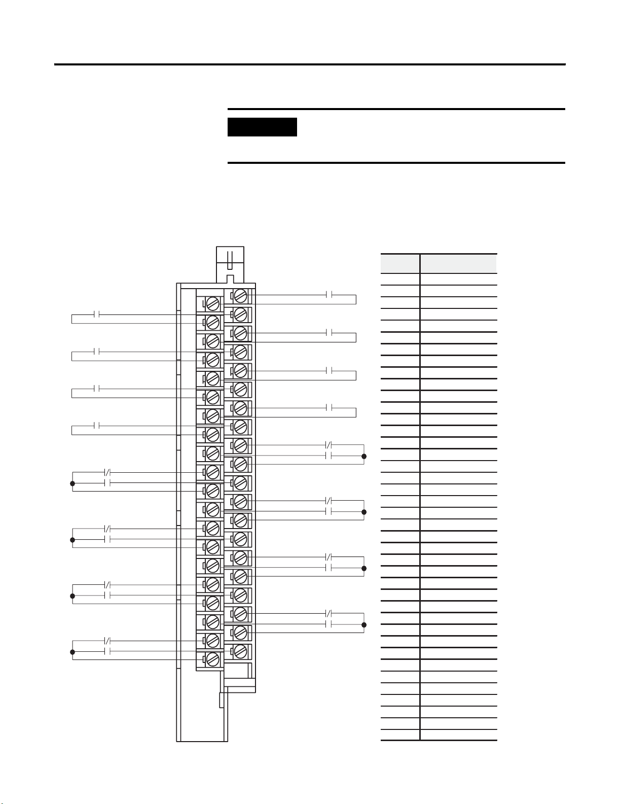
IMPORTANT
The field wiring arm terminal identification number is not
the same as the number of the bit which controls that
output
For operating voltages in excess of 125V, use the same phase to maintain
channel-to-channel isolation.
Connection Diagram for the 1771-OW16 Contact Output Module
Output 01
Common 01
Output 03
Common 03
Output 05
Common 05
Output 07
Common 07
Output 11 (NC)
Output 11 (NO)
Common 11
Output 13 (NC)
Output 13 (NO)
Common 13
Output 15 (NC)
Output 15 (NO)
Common 15
Output 17 (NC)
Output 17 (NO)
Common 17
Output 00
2
4
6
8
10
12
14
16
18
20
22
24
26
28
30
32
34
36
38
40
Common 00
Output 02
Common 02
Output 04
Common 04
Output 06
Common 06
Output 10 (NC)
Output 10 (NO)
Common 10
Output 12 (NC)
Output 12 (NO)
Common 12
Output 14 (NC)
Output 14 (NO)
Common 14
Output 16 (NC)
Output 16 (NO)
Common 16
Terminal Function
Output 00 (NO)
1
Common for output 00
2
Output 01 (NO)
3
4
Common for output 00
Output 01 (NO)
5
6
Common for output 00
Output 03 (NO)
7
8
Common for output 00
Output 04 (NO)
9
10
Common for output 00
11
Output 05 (NO)
12
Common for output 00
Output 06 (NO)
Common for output 00
Output 07 (NO)
Common for output 00
Output 10 (NC)
Output 10 (NO)
Common for output 00
Output 11 (NC)
Output 11 (NO)
Common for output 00
Output 12 (NC)
Output 12 (NO)
Common for output 00
Output 13 (NC)
Output 13 (NO)
Common for output 00
Output 14 (NC)
Output 14 (NO)
Common for output 00
Output 15 (NC)
Output 15 (NO)
Common for output 00
Output 16 (NC)
Output 16 (NO)
Common for output 00
Output 17 (NC)
Output 17 (NO)
Common for output 00
13
14
15
16
17
18
19
20
21
22
23
24
25
26
27
28
29
30
31
32
33
34
35
36
37
38
39
40
Publication 1771-IN069B-EN-P - November 2005
Page 10

10 Electromechanical Relay Contact Output Module
You can use an output of the 1771-OW16 series B module to drive an input of
a 1771-ac/dc input module (1771-IAD series B) to indicate the status of
turning on a motor starter, for example (see the following figure). Inputs
configured with the output module are not isolated from each other.
.
ATTENTION
L1
ac High
Do not attempt to increase load current or wattage
capability beyond the maximum rating by connecting two
or more outputs in parallel. The slightest variation in relay
switching time may cause one relay to momentarily switch
the total load current.
Contact Output Module
Cat. No. 1771-OW16 series B
Output 0
2
4
6
8
10
12
14
16
18
20
22
24
26
28
30
32
34
36
38
40
ac/dc (120V) Input Module
Cat. No. 1771-IAD series B
Input 00
Input 01
Input 02
Input 03
Input 04
Input 05
Input 06
Input 07
Input 10
Input 11
Input 12
Input 13
Input 14
Input 15
Input 16
Input 17
L2
ac Low
Publication 1771-IN069B-EN-P - November 2005
Page 11

Electromechanical Relay Contact Output Module 11
Interpret the Status Indicators
The module has 16 output status indicators (see below). Each indicator
represents the system side control status of the corresponding output relay.
Each indicator is on when its corresponding relay is energized.
00
11
01
10
02
12
03
13
04
14
05
15
06
16
07
17
Output State Indicators (red)
Publication 1771-IN069B-EN-P - November 2005
Page 12

12 Electromechanical Relay Contact Output Module
Specifications
Specifications ac/dc (240V ac/150V dc) Electromechanical Relay
Contact Output Module (cat. no. 1771-OW16)
Number of Outputs 16
Module Location 1771-I/O Chassis, 1 slot
Voltage Rating 240V ac @ 47-63 Hz; 150V dc - Refer to page 14
Current Rating Refer to Tab le 2 on page 14
Maximum surge current dc: 2 A max per output (at rated power)
Minimum Contact Load
Operate/Release Time 10 ms maximum; 5 ms (+1 ms)
Switching Frequency 1/3 Hz at maximum load
Bounce Time 4.0 ms maximum
Expected Life of
Electrical Contacts
Backplane Current 1.3 A maximum
Power Dissipation All relays on: 6.5 Watts
Thermal Dissipation All relays on: 22.24 BTU/hr
Isolation Voltage
(continuous-voltage withstand
rating)
Fusing Fusing of outputs is recommended. Use 3.0 A, 250V ac slow-blow fuses
External Over-current Protection 15 A branch circuit protection
Indicators 8 yellow status indicators - show status of individual outputs. If relay output
Environmental Conditions
Operating Temperature IEC 60068-2-1 (Test Ad, Operating Cold),
Storage Temperature IEC 60068-2-1 (Test Ab, Unpackaged Nonoperating Cold),
Relative Humidity IEC 60068-2-30 (Test Db, Unpackaged nonoperating Damp Heat):
Vibration IEC 60068-2-6 (Test Fc, Operating):
Shock
ESD Immunity IEC 61000-4-2:
Radiated RF Immunity IEC 61000-4-3:
EFT/B Immunity IEC 61000-4-4:
Surge Transient Immunity IEC 61000-4-5:
Conducted RF Immunity IEC 61000-4-6:
Emissions CISPR 11:
Enclosure Type Rating None (open-style)
Conductors Wire Size
Field Wiring Arm Catalog Number 1771-WN
Field Wiring Arm Screw Torque 1.0 Nm (9 pound-inches)
1
Operating
Nonoperating
Category
ac: Refer to Ta bl e 3 on page 14
10 mA
300 K operations @ 25 °C (cos θ = 1)
250V basic system to user side
125V basic between channels
Tested to 1500 V ac for 60 s
(Littelfuse pt. no. 239003).
bit is on, corresponding output indicator is on.
IEC 60068-2-2 (Test Bd, Operating Dry Heat),
IEC 60068-2-14 (Test Nb, Operating Thermal Shock):
0 to 60 °C (32 to 140 °F)
IEC 60068-2-2 (Test Bb, Unpackaged Nonoperating Dry Heat),
IEC 60068-2-14 (Test Na, Unpackaged Nonoperating Thermal Shock):
–40 to 85 °C (–40 to 185 °F)
5 to 95% noncondensing
2g @ 10…500 Hz
IEC 60068-2-27 (Test Ea, Unpackaged Shock):
30g
50g
6 kV indirect contact discharges
10 V/m with 1kHz sine-wave 80%AM from 30 MHz to 1000 MHz
±1 kV at 5 kHz on signal ports
±1 kV line-line(DM) and ±2 kV line-earth(CM) on signal ports
10 Vrms with 1 kHz sine-wave 80%AM from 150 kHz to 30 MHz
Group 1, Class A (with appropriate enclosure)
0.34…2.5 mm2 (22…14 AWG) stranded copper wire rated at 75 °C or higher
1.2 mm (3/64 inch) insulation maximum
2
2 - on signal ports
Publication 1771-IN069B-EN-P - November 2005
Page 13

Electromechanical Relay Contact Output Module 13
Keying between 2 and 4
between 32 and 34
Certifications (when product is
3
marked)
UL UL Listed Industrial Control Equipment
CSA CSA certified Process Control Equipment
CSA CSA certified Process Control Equipment for Class I, Division 2,
Groups A, B, C and D Hazardous locations
CE European Union 89/336/EEC EMC Directive, compliant with:
EN 61000-6-4; Industrial Emissions
EN 50082-2; Industrial Immunity
EN 61326; Meas./Control/Lab., Industrial Requirements
EN 61000-6-2; Industrial Immunity
CE European Union 73/23/EEC LVD Directive, compliant with:
61131-2 - Programmable Controllers
C-Tick Australian Radiocommunications Act compliant with
AS/NZS CISPR 11, Industrial Emissions
1 Minimum switching loads mentioned above are reference values. Please perform the confirmation test with the actual load
before production since reference values may vary according to switching frequencies, environmental conditions and expected
reliability levels
2 You use this category information for planning conductor routing as described in Allen-Bradley
publication 1770-4.1, Industrial Automation Wiring and Grounding Guidelines.
3 For the latest up-to-date information, see the Product Certification link at www.ab.com for Declarations of Conformity,
Certificates and other certification details.
Publication 1771-IN069B-EN-P - November 2005
Page 14

14 Electromechanical Relay Contact Output Module
Figure 1 Maximum Switching Power
2.0
1.0
0.5
Current (A)
0.2
0.1
10 20 50 100 200 500
Voltage (V dc)
Table 1 UL and CSA Ratings
Amperes Voltage
2 250V ac, resistive
2 30V dc, resistive
2 250V ac, 50/60 Hz, 360 VA
Note: All ac voltages must be the same phase.
Table 2 Manufacturer Ratings - Resistive
ac dc
Maximum Switching Power 500 VA See Figure 1, Switching Power
Maximum Switching Voltage 250 VA 150V
Maximum Switching Current 2 A 2 A
Module Maximum Switching Power 1440 VA 1280 W
Table 3 Maximum ac Surge Current
Maximum Contact Rating
ac
Voltage
Amperes
Continuous
Carrying Current
Maximum
Voltamperes
Make Break Make Break
120 30 3 2 3600 360
240 15 1.5 2 3600 360
ATTENTION
Any use of this module outside the listed ratings is not
allowed in applications requiring a listed system.
Publication 1771-IN069B-EN-P - November 2005
Page 15

Figure 2 Derating Curve
18
16
14
12
10
8
6
Adjacent Slot Power (W)
4
2
Electromechanical Relay Contact Output Module 15
0
54 60
Ambient Temperature (˚C)
Publication 1771-IN069B-EN-P - November 2005
Page 16

Rockwell Automation Support
Rockwell Automation provides technical information on the web to assist you in using our products. At
http://support.rockwellautomation.com, you can find technical manuals, a knowledge base of FAQs, technical and application
notes, sample code and links to software service packs, and a MySupport feature that you can customize to make the best use of
these tools.
For an additional level of technical phone support for installation, configuration and troubleshooting, we offer TechConnect
Support programs. For more information, contact your local distributor or Rockwell Automation representative, or visit
http://support.rockwellautomation.com.
Installation Assistance
If you experience a problem with a hardware module within the first 24 hours of installation, please review the information that's
contained in this manual. You can also contact a special Customer Support number for initial help in getting your module up and
running:
United States 1.440.646.3223
Monday – Friday, 8am – 5pm EST
Outside United States Please contact your local Rockwell Automation representative for any technical support issues.
New Product Satisfaction Return
Rockwell tests all of our products to ensure that they are fully operational when shipped from the manufacturing facility. However,
if your product is not functioning and needs to be returned:
United States Contact your distributor. You must provide a Customer Support case number (see phone number
above to obtain one) to your distributor in order to complete the return process.
Outside United States Please contact your local Rockwell Automation representative for return procedure.
Publication 1771-IN069B-EN-P - November 2005 16 PN 957974-53
Supersedes Publication 1771-5.69 - January 1999 Copyright © 2005 Rockwell Automation, Inc . All rights reserved. Printed in the U.S.A.
 Loading...