

Page 1

Installation Instructions
Isolated 24V dc Output Module
(Cat. No. 1771-OQ Series B)
Contents
Important User Information
Use this document as a guide when installing the catalog number 1771-OQ
Series B isolated dc output module.
To See page
Important User Information 1
Preinstallation Considerations 3
Set the Jumper Configuration 3
Calculate Power Requirements 4
Key the Backplane Connector 5
Install the Field Wiring Arm 5
Connect Wiring to the Field Wiring Arm 6
Interpreting the Status Indicators 8
Replacing the Fuses 8
Specifications 9
Solid state equipment has operational characteristics differing from those of
electromechanical equipment. Safety Guidelines for the Application, Installation and
Maintenance of Solid State Controls (Publication SGI-1.1 available from your local
Rockwell Automation sales office or online at http://www.ab.com/manuals/gi)
describes some important differences between solid state equipment and hard-wired
electromechanical devices. Because of this difference, and also because of the wide
variety of uses for solid state equipment, all persons responsible for applying this
equipment must satisfy themselves that each intended application of this equipment is
acceptable.
In no event will Rockwell Automation, Inc. be responsible or liable for indirect or
consequential damages resulting from the use or application of this equipment.
The examples and diagrams in this manual are included solely for illustrative purposes.
Because of the many variables and requirements associated with any particular
installation, Rockwell Automation, Inc. cannot assume responsibility or liability for
actual use based on the examples and diagrams.
No patent liability is assumed by Rockwell Automation, Inc. with respect to use of
information, circuits, equipment, or software described in this manual.
Reproduction of the contents of this manual, in whole or in part, without written
permission of Rockwell Automation, Inc. is prohibited.
1 Publication 1771-IN081B-EN-P - June 2004
Page 2
2 Isolated 24V dc Output Module
Throughout this manual we use notes to make you aware of safety considerations.
WARNING
IMPORTANT
ATTENTION
ATTENTION
Identifies information about practices or circumstances
that can cause an explosion in a hazardous environment,
which may lead to personal injury or death, property
damage, or economic loss.
Identifies information that is critical for successful
application and understanding of the product.
Identifies information about practices or circumstances that can
lead to personal injury or death, property damage, or economic
loss. Attentions help you:
• identify a hazard
• avoid a hazard
• recognize the consequence
Environment and Enclosure
This equipment is intended for use in a Pollution Degree 2 industrial
environment, in overvoltage Category II applications (as defined in IEC
publication 60664-1), at altitudes up to 2000 meters without derating.
This equipment is considered Group 1, Class A industrial equipment
according to IEC/CISPR Publication 11. Without appropriate
precautions, there may be potential difficulties ensuring electromagnetic
compatibility in other environments due to conducted as well as radiated
disturbance.
This equipment is supplied as "open type" equipment. It must be
mounted within an enclosure that is suitably designed for those specific
environmental conditions that will be present and appropriately designed
to prevent personal injury resulting from accessibility to live parts. The
interior of the enclosure must be accessible only by the use of a tool.
Subsequent sections of this publication may contain additional
information regarding specific enclosure type ratings that are required to
comply with certain product safety certifications.
See NEMA Standards publication 250 and IEC publication 60529, as
applicable, for explanations of the degrees of protection provided by
different types of enclosure. Also, see the appropriate sections in this
publication, as well as the Allen-Bradley publication 1770-4.1 ("Industrial
Automation Wiring and Grounding Guidelines"), for additional
installation requirements pertaining to this equipment.
Publication 1771-IN081B-EN-P - June 2004
Page 3
Isolated 24V dc Output Module 3
Preinstallation Considerations
Set the Jumper Configuration
ATTENTION
Preventing Electrostatic Discharge
This equipment is sensitive to electrostatic discharge, which can cause
internal damage and affect normal operation. Follow these guidelines
when you handle this equipment:
• Touch a grounded object to discharge potential static.
• Wear an approved grounding wriststrap.
• Do not touch connectors or pins on component boards.
• Do not touch circuit components inside the equipment.
• If available, use a static-safe workstation.
• When not in use, store the equipment in appropriate static-safe
packaging.
This module contains soldered jumpers which must be removed when using
certain output devices, such as solenoids. These jumpers limit the effects of
noise. These jumpers are not reusable. Make certain that you will not be using
a particular output for other uses before clipping the jumper.
Your module contains a jumper for each output. Under normal conditions,
these jumpers are left in the position as shipped. When using solenoids as an
output device, remove the jumper on the circuit board. Removing the jumper
changes the off-state clamping voltage from -0.7V dc to -15.7V dc. This
decreases the turnoff time of the solenoid, allowing it to energize faster.
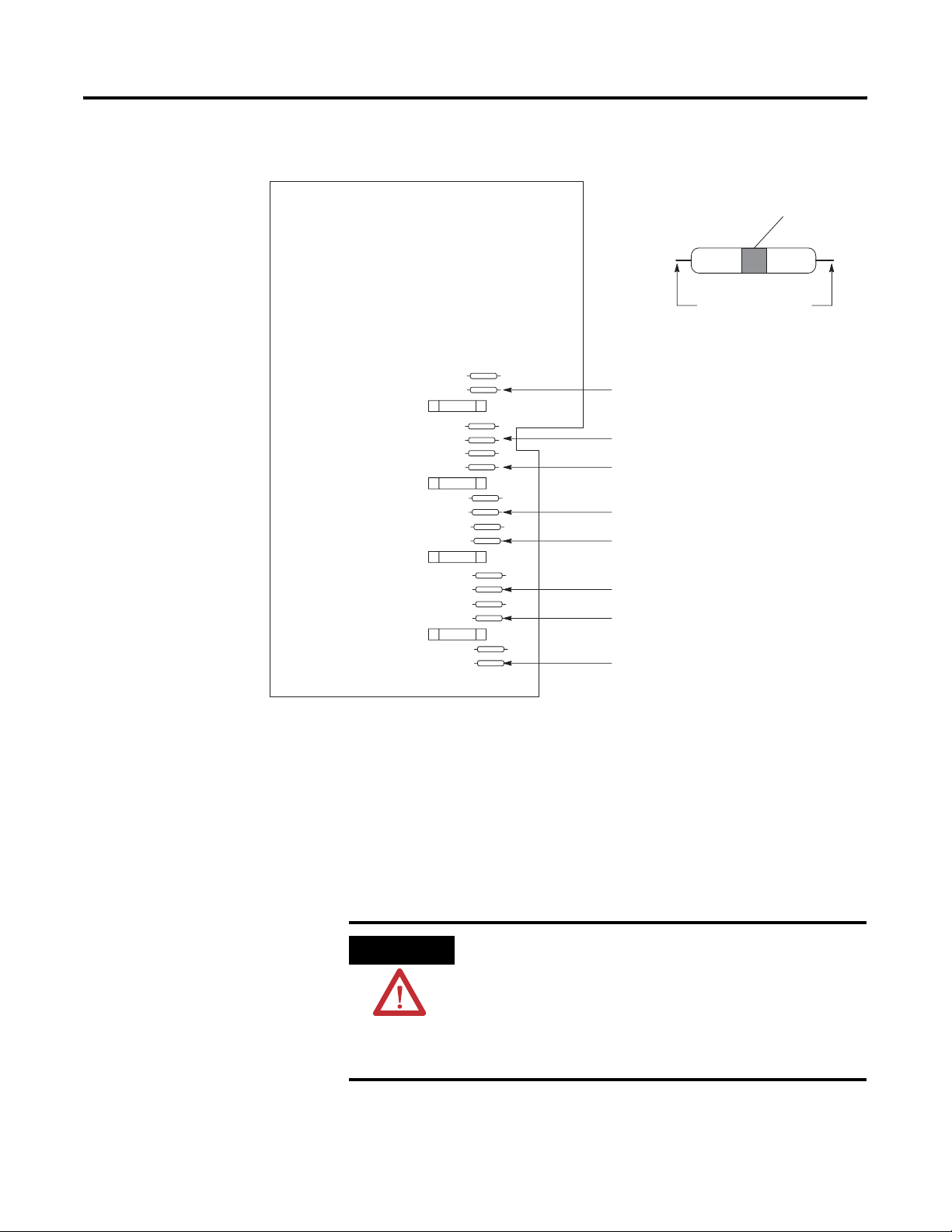
Follow the procedure listed below for removing a jumper. Refer to Figure 1.
1. Remove the plastic cover on the left front side of the module by
removing two screws.
2. Locate the jumper which corresponds to your output. Note: The
jumpers are usually brown with a black band.
3. Clip both ends of the jumper with diagonal cutters.
ATTENTION
Do not use a soldering tool to remove the jumper. This
could cause damage to the adjacent components or the
entire circuit board.
4. Replace the cover and secure with two screws
Publication 1771-IN081B-EN-P - June 2004
Page 4
4 Isolated 24V dc Output Module
Figure 1
Configuration Jumper Locations
Black Band
Clip leads here.
Jumper 1 - corresponds to output 0
Jumper 2 - corresponds to output 1
Jumper 3 - corresponds to output 2
Jumper 4 - corresponds to output 3
Calculate Power Requirements
Jumper 5 - corresponds to output 4
Jumper 6 - corresponds to output 5
Jumper 7 - corresponds to output 6
Jumper 8 - corresponds to output 7
1065-I
1
The module receives its power through the 1771 I/O chassis backplane from
the chassis power supply. The module requires 225mA from the output of this
supply .
Add this current to the requirements of all other modules in the I/O chassis to
prevent overloading the chassis backplane and/or backplane power supply.
ATTENTION
Do not insert or remove modules from the I/O chassis
while system power is applied. Failure to observe this rule
could result in:
Publication 1771-IN081B-EN-P - June 2004
• module damage or degradation of performance
• injury or equipment damage due to possible
unexpected operation.
Page 5

Isolated 24V dc Output Module 5
Key the Backplane Connector
ATTENTION
Observe the following precautions when inserting or removing keys:
• insert or remove keys with your
fingers
• make sure that key placement is
correct
Incorrect keying or the use of a tool can
result in damage to the backplane connector
and possible system faults.
Install the Field Wiring Arm
Place your module in any slot in the chassis except the leftmost slot which is
reserved for processors or adapters.
Position the keying bands in the backplane connectors to
ATTENTION
correspond to the key slots on the module.
I/O chassis
Y ou can change the position of these bands if
subsequent system design and rewiring makes
insertion of a different type of module necessary.
.
Remove power from the 1771 I/O chassis backplane and
Place the keying bands:
- between 2 and 4
- between 10 and 12
Upper
Connector
11022-I
field wiring arm before removing or installing the I/O
module. Failure to remove power from the backplane or
wiring arm could cause:
Place the module in the card guides on the top and bottom of the
1
chassis that guide the module into position.
Important: Apply firm even pressure on the module to seat it
into its backplane connector .
1771-A1B, -A2B, -A3B, -A4B I/O chassis
Snap the chassis latch over
the top of the module to
secure it.
• module damage, degradation of performance, or
injury.
• injury or equipment damage due to possible
unexpected operation.
1771-A1B, -A2B, -A4B Series B I/O chassis
Swing the chassis locking bar
down into place to secure the
modules. Make sure the
locking pins engage.
Publication 1771-IN081B-EN-P - June 2004
Page 6

6 Isolated 24V dc Output Module
Attach the wiring arm (1771-WF) to the horizontal bar
2
at the bottom of the I/O chassis.
The wiring arm pivots upward and connects with the
module so you can install or remove the module
without disconnecting the wires.
1771-WF
The 1771-OQ module is a modular component of the 1771 I/O system
requiring a properly installed system chassis. Refer to publication 1771-IN075
for detailed information on acceptable chassis, proper installation, and
grounding requirements. Limit the maximum adjacent slot power dissipation
to 15.5W maximum.
Connect Wiring to the Field Wiring Arm
Make wiring connections to the module through the field wiring arm (cat. no.
1771-WF). The arm pivots on the I/O chassis to connect with terminals on
the front of the module and acts as a terminal strip. The wiring arm allows the
module to be removed from the chassis without disconnecting the wiring.
ATTENTION
Remove power from the 1771 I/O chassis backplane and
field wiring arm before removing or installing the I/O
module.
• Failure to remove power from the backplane or wiring
arm could cause module damage, degradation of
performance, or injury.
• Failure to remove power from the backplane could
cause injury or equipment damage due to possible
unexpected operation.
1. Make certain all power is removed from the module before making
wiring connections.
2. Swing the wiring arm up into position on the front of the module. The
locking tab on the module will secure it into place.
Publication 1771-IN081B-EN-P - June 2004
IMPORTANT
The field wiring arm terminal identification number is not
the same as the number of the bit which controls that
output
Page 7

Figure 2
Connection Diagram
Isolated 24V dc Output Module 7
Not used
+24V dc
Output 0
Output 1
dc Common
dc Common
Output 2
Output 3
+24V dc
+24V dc
Output 4
Output 5
dc Common
dc Common
Output 6
Output 7
+24V dc
Not used
18
17
16
15
14
13
12
11
10
9
8
7
6
5
4
3
2
1
+
dc
Output Device
+
dc
Output Device
+
dc
Output Device
+
dc
Output Device
+
dc
Output Device
-
-
dc
Output Device
+
+
dc
Output Device
-
-
dc
Output Device
+
-
-
-
-
+
-
+
-
User 24V
dc Supply
-
User 24V
dc Supply
+
User 24V
dc Supply
-
User 24V
dc Supply
+
Field Wiring Arm
Cat. No. 1771-WF
1
1066-I
(Actual wiring runs in this direction.)
Connect your output device wiring to the field wiring arm as shown in Figure
2. Use two wires per output. Connect only one wire to a terminal. When
multiple connections to a terminal are required, use an auxiliary terminal strip.
Use stranded 14 gauge wire to minimize the voltage drop over long cable
distances.
ATTENTION
Observe proper polarity with dc power connections.
Reverse polarity, or application of ac voltage could damage
the module.
Publication 1771-IN081B-EN-P - June 2004
Page 8

8 Isolated 24V dc Output Module
Interpreting the Status Indicators
Replacing the Fuses
The front panel of your module contains 8 red status indicators (below). The
red status indicators are on when the associated output is on.
Not used
Output 0
Output 1
Output 2
Output 3
Output 4
Output 5
Output 6
Output 7
Status Indicators
1067-I
1
To replace a blown fuse, proceed as follows:
ATTENTION
Remove power from the 1771 I/O chassis backplane and
field wiring arm before removing or installing an I/O
module.
• Failure to remove power from the backplane or wiring
arm could cause module damage, degradation of
performance, or injury.
• Failure to remove power from the backplane could
cause injury or equipment damage due to possible
unexpected operation.
1. Turn off power to the chassis.
2. Remove the module from the I/O chassis.
3. Remove the 2 screws securing the front cover on the unlabelled side of
the module. Note: One fuse protects 2 outputs.
4. Remove the blown fuse from fuse holder, and replace with a 2.5A, 3AG
normal blow fuse.
5. Replace the cover and secure with screws removed in step 3.
6. Reinsert the module into I/O chassis.
Publication 1771-IN081B-EN-P - June 2004
7. Turn on power to chassis.
Page 9

Specifications
Isolated 24V dc Output Module 9
Specifications
Outputs per Module 8 (4 groups of 2, each group sharing a common dc supply)
Module Location 1771-A1B, thru -A4B or later I/O chassis
Output Voltage Range 24V dc, 2.25A, 4A inrush derated linearly from 37°C to 1.25A, 24V dc
@ 60°C
2.25A per group derated linearly from 37°C to 1.25A
Maximum Output Current 2.25A per output
2.25A per group
9.0A per module
Maximum Surge Current 4.0A for 10ms per output
Maximum On-state Voltage
Drop
Maximum Off-stage Leakage
Current
Maximum Power Rating 4.5W per output
Output Signal Delay 10ms on or off
Power Dissipation 19.1W (max.), 1.1W (min.)
Thermal Dissipation 65.1 BTU/hr (max.), 3.75 BTU/hr (min.)
Backplane Current 225mA @ 5V
Isolation Voltage 50V continuous, tested to withstand 500V for 60s
Envitonmental Conditions
Operating Temperative IEC 60068-2-1 (Test Ad, Operating Cold),
Storage Temperature IEC 60068-2-1 (Test Ab, Unpackaged Nonoperating Cold),
Relative Humidity IEC 60068-2-30 (Test Db, Unpackaged Nonoperating Damp Heat):
Shock
Operating
Nonoperating
Vibration IEC 60068-2-6 (Test Fc, Operating):
Radiated RF Immunity IEC 61000-4.3
EFT/B Immunity IEC 61000-4.4
Surge Transient Immunity IEC 61000-4.5
Conducted RF Immunity IEC 61000-4.6
2V dc @ 2.25A
1.0mA per output @ 34V dc, 25°C
IEC 60068-2-2 (Test Bd, Operating Dry Heat),
IEC 60068-2-14 (Test Nb, Operating Thermal Shock):
0 to 60°C (32 to 140°F)
IEC 60068-2-2 (Test Bb, Unpackaged Nonoperating Dry Heat),
IEC 60068-2-14 (Test Na, Unpackaged Nonoperating Thermal Shock):
-40 to 85°C (-40 to 185°F)
5 to 95% noncondensing
IEC 60068-2-27 (Test Ea, Unpackaged Shock):
30g
50g
2g @ 10-500Hz
10V/m with 1kHz sine-wave 80%AM from 30MHz to 1000MHz
10V/m with 200Hz 50% Pulse 100%AM at 900Mhz
±1kV at 5kHz on signal ports
±1kV line-line(DM) and ±2kV line-earth(CM) on signal ports
10Vrms with 1kHz sine-wave 80%AM from 150kHz to 30MHz
Publication 1771-IN081B-EN-P - June 2004
Page 10

10 Isolated 24V dc Output Module
Specifications
Emmisions CISPR 11
Group 1, Class A (with appropriate enclosure)
Enclosure Type Rating None (open-style)
Fuse 2.5A, 250V normal blow fuse, Cooper Bussman AGC 2.5 or Littelfuse
31202.5
Field Wiring Arm Cat. No. 1771-WF
Wiring Arm Screw Torque 7 pound-inches (0.8Nm)
Conductors
Wire Size
Category
Certification (when product is
marked)
1 You use this conductor category information for planning routing as described in publication 1770-4.1, Industrial Automation
Wiring and Grounding Guidelines.
2 See the Product Certification link at www.ab.com for Declarations of Conformity, Certificates and other certification details.
14AWG (2.5mm2) stranded copper rated at 60°C or greater
3/64 inch (1.2mm) insulation (maximum)
1
2
UL UL Listed Industrial Control Equipment
CSA CSA Certified Process Control Equipment
2
CE
European Union 89/336/EEC EMC Directive, compliant with:
EN 50082-2, Industrial Immunity
EN 61326, Meas./Control/Lab., Industrial Requirements
EN 61000-6-2, Industrial Immunity
EN 61000-6-4, Industrial Emissions
C-Tick2Australian Radiocommunications Act, compliant with:
AS/NZS CISPR 11, Industrial Emissions
Derating Curve for the 1771-OQ Output Module
2.50
2.25
2.0
1.75
1.50
1.25
1.0
Module Output Current - A
0.75
0.5
0.25
0
010 203040 50 60
T emperature (˚C)
Publication 1771-IN081B-EN-P - June 2004
Page 11

Isolated 24V dc Output Module 11
Publication 1771-IN081B-EN-P - June 2004
Page 12

Rockwell Automation Support
Rockwell Automation provides technical information on the web to assist you in using our products. At
http://support.rockwellautomation.com, you can find technical manuals, a knowledge base of FAQs, technical and
application notes, sample code and links to software service packs, and a MySupport feature that you can customize
to make the best use of these tools.
For an additional level of technical phone support for installation, configuration and troubleshooting, we offer
TechConnect Support programs. For more information, contact your local distributor or Rockwell Automation
representative, or visit http://support.rockwellautomation.com.
Installation Assistance
If you experience a problem with a hardware module within the first 24 hours of installation, please review the
information that's contained in this manual. You can also contact a special Customer Support number for initial help
in getting your module up and running:
United States 1.440.646.3223
Monday – Friday, 8am – 5pm EST
Outside United States Please contact your local Rockwell Automation representative for any technical support issues.
New Product Satisfaction Return
Rockwell tests all of our products to ensure that they are fully operational when shipped from the manufacturing
facility. However, if your product is not functioning and needs to be returned:
United States Contact your distributor. You must provide a Customer Support case number (see phone number
above to obtain one) to your distributor in order to complete the return process.
Outside United States Please contact your local Rockwell Automation representative for return procedure.
Publication 1771-IN081B-EN-P - June 2004 12 PN 957899-57
Supersedes Publication 1771-IN081A -EN-P - August 2003 Copyright © 2004 Rockwell Automation, Inc . All rights reserved. Printed in the U.S.A.
 Loading...