

Page 1

Installation Instructions
AC (24V) Output Module
Cat. No. 1771-OND Series B
To The Installer
Preinstallation
Considerations
European Union Directive Compliance
This document provides information on:
• important pre-installation considerations
• power supply requirements
• installing the module
• setting the fault mode
• using the indicators for troubleshooting
• replacing the fuses
• module specifications
This module must be used with a 1771-A1B thru -A4B or later I/O
chassis. If you are using a 1771-ASB remote I/O adapter you may
use any combination of I/O modules. Otherwise, make sure no other
output module or single card block transfer module is placed in the
same I/O group.
If this product has the CE mark it is approved for installation within
the European Union and EEA regions. It has been designed and
tested to meet the following directives.
EMC Directive
This product is tested to meet Council Directive 89/336/EEC
Electromagnetic Compatibility (EMC) and the following standards,
in whole or in part, documented in a technical construction file:
• EN 50081-2EMC – Generic Emission Standard, Part 2 –
Industrial Environment
• EN 50082-2EMC – Generic Immunity Standard, Part 2 –
Industrial Environment
This product is intended for use in an industrial environment.
Publication 17715.41 - May 1996
Page 2
AC (24V) Output Module2
Low Voltage Directive
This product is tested to meet Council Directive 73/23/EEC
Low Voltage, by applying the safety requirements of EN 61131–2
Programmable Controllers, Part 2 – Equipment Requirements and
Tests.
For specific information required by EN 61131-2, see the appropriate
sections in this publication, as well as the following Allen-Bradley
publications:
• Industrial Automation Wiring and Grounding Guidelines For
Noise Immunity, publication 1770-4.1
• Guidelines for Handling Lithium Batteries, publication AG-5.4
• Automation Systems Catalog, publication B111
Power Requirements
Initial Handling
Your module receives its power through the 1771 I/O chassis
backplane from the chassis power supply. The module requires
700mA from the output of this supply. Add this to the requirements
of all other modules in the I/O chassis to prevent overloading the
chassis backplane and/or backplane power supply.
The ac output module is shipped in a static-shielded bag to guard
against electrostatic discharge damage. Observe the following
precautions when handling the module.
Electrostatic Discharge Damage
ATTENTION: Under some conditions, electrostatic
discharge can degrade performance or damage the
!
module. Observe the following precautions to guard
against electrostatic damage.
• Wear an approved wrist strap grounding device, or touch a
grounded object to discharge yourself before handling the
module.
• Do not touch the backplane connector or connector pins.
• If you configure or replace internal components, do not touch
other circuit components inside the module. If available, use a
static-free work station.
• When not in use, keep the module in a static-shielded bag.
Publication
17715.41 - May 1996
Page 3
AC (24V) Output Module 3
Installing Your Module
In this section we tell you how to set the fault mode selection plug,
key your I/O chassis, install your module and make your wiring
connections.
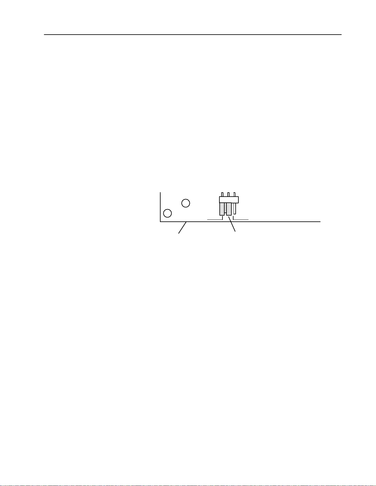
Fault Mode Selection
You may select one of two output-failure configurations (last state or
reset) by positioning a configuration plug on the bottom edge of the
printed circuit board. This configuration plug is independent of the
last state switch on the I/O chassis backplane.
To set the fault mode selection, proceed as follows:
1. Locate the fault mode selection plug at the bottom edge of the
module circuit board (Figure 1).
Figure 1
Mode Selection Plug
Fault
LS RESET
Bottom edge of circuit board
Fault Mode Selection Plug
(shown in last state position)
10673-I
2. Using your finger, slide the plug off the two posts.,
3. Carefully position the plug on two of the three posts that
correspond to your requirement.
Keying Your I/O Chassis
Use the plastic keying bands, shipped with each I/O chassis, to key
the I/O slots to accept only this type of module.
The module circuit board is slotted in two places on the rear edge.
The position of the keying bands on the backplane connector must
correspond to these slots to allow insertion of the module. You can
key any connector in an I/O chassis to receive this module except for
the left-most connector reserved for adapter or processor modules.
Place keying bands between the following numbers labeled on the
backplane connector:
• Between 20 and 22
• Between 32 and 34
You can change the position of these keys if system redesign and
rewiring makes insertion of a different module necessary.
Publication
17715.41 - May 1996
Page 4

AC (24V) Output Module4
Installing the Output Module
To install the ac output module in your 1771 I/O chassis, follow the
steps listed below.
ATTENTION: Remove power from the 1771 I/O
chassis backplane and wiring arm before removing or
!
installing the module.
• Failure to remove power from the backplane or field
wiring arm could cause module damage, degradation
of performance, or injury.
• Failure to remove power from the backplane could
cause injury or equipment damage due to possible
unexpected operation.
1. Turn off power to the I/O chassis.
2. Place the module in the plastic tracks on the top and bottom of the
slot that guides the module into position.
3. Do not force the module into its backplane connector. Apply firm,
even pressure on the module to seat it properly.
4. Snap the chassis latch over the top of the module to secure its
position.
5. Connect the wiring arm to the module.
6. Make wiring connections to the field wiring arm as indicated in
Figure 2.
Publication
17715.41 - May 1996
Page 5

AC (24V) Output Module 5
Connecting Wiring to the Output Module
Connections to the output module are made to the field wiring arm
(cat. no. 1771-WH) shipped with the module. An optional fused
wiring arm is available (cat. no. 1771-WHF) which provides
individual fusing for each circuit. Attach the wiring arm to the pivot
bar on the bottom of the I/O chassis. The wiring arm pivots upward
and connects with the module so you can install or remove the
module without disconnecting the wires.
You must supply ac (L1) at terminals A through D on the wiring
arm. You need four ac connections to accommodate the total
required surge rating on the module without overstressing any single
connection on the field wiring arm. Jumper all ac (L1) connections
together to prevent module damage.
Figure 2
Connection
Diagram
Terminal A
Terminal B
Terminal C
Terminal D
Output 00
Output 01
Output 02
Output 03
Output 04
Output 05
Output 06
Output 07
Output 10
Output 11
Output 12
Output 13
Output 14
Output 15
Output 16
Output 17
Terminal E
A
B
C
D
00
01
02
03
04
05
06
07
10
11
12
13
14
15
16
17
E
(Actual wiring runs in this direction.)
L1
24V ac
Output
Device
L2
ac Low
10674I
Publication
17715.41 - May 1996
Page 6

AC (24V) Output Module6
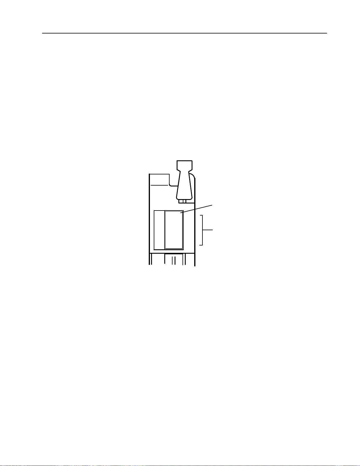
Important: You can use an AC (24V) Output Module (cat. no.
1771-OND) to directly drive terminals on an AC (24V)
Input Module (cat. no. 1771-IND) (Figure 3). You can
also use a 1771-OND Output module to drive an AC
(24V) Input Module (cat. no. 1771-IN) but you must
connect a 250 ohm, 5W resistor between the output
terminal and L2 (common) as shown in Figure 3. Use
the same ac power source to power both modules to
ensure proper phasing and prevent module damage.
Figure 3
an Input Module with an Output Module
Driving
AC (24V)
Output Module
(Cat. No. 1771OND)
L1
24V ac High
AC (24V)
Input Module
(Cat. No. 1771IND)
AC (24V)
Output Module
(Cat. No. 1771OND)
AC (24V)
Input Module
(Cat. No. 1771IN)
L1
24V ac High
250 ohm 5W
resistor
Publication
ac Low
Note: 1771OND output voltage
range is 1060V ac. However, the
onstate voltage range of the
1771IND is 1929V ac.
17715.41 - May 1996
L2
L2
L2
ac Low
Note: 1771OND output voltage
range is 1060V ac. However, the
onstate voltage range of the
1771IN is 1228V ac.
Page 7
AC (24V) Output Module 7
Interpreting the Status Indicators
The front panel of your module contains one green, module active
indicator, and 16 red status indicators (Figure 4). The 1771-OND
performs diagnostics in a handshaking mode when first powered up.
Upon successful completion of the diagnostics, the green module
active indicator lights. It turns off if a fault occurs in the data paths
or the opto-isolators.
The red status indicators are provided for system logic side
indication of individual inputs. When a red indicator lights, voltage
is present on the terminal. The module transfers this information to
the backplane for the processor to read.
Figure 4
Indicators
Status
Module Active Indicator (green)
ACTIVE
00
10
01
11
02
12
03
13
04
14
05
15
06
16
07
17
00 to 17 Status Indicators (red)
10676I
Publication
17715.41 - May 1996
Page 8

AC (24V) Output Module8
Replacing the Fuse
The module’s output circuitry is protected from overload or shorts by
a fuse. You can replace the fuse as outlined below.
1. Turn off all power to the I/O chassis and all output device power
to the field wiring arm.
ATTENTION: Remove power from the 1771 I/O
chassis backplane and wiring arm before removing or
!
installing the module.
• Failure to remove power from the backplane or field
wiring arm could cause module damage, degradation
of performance, or injury.
• Failure to remove power from the backplane could
cause injury or equipment damage due to possible
unexpected operation.
2. Pivot the wiring arm away from the module and remove the
module from the chassis.
3. Replace the blown fuse with a 10A, 250V rectifier fuse (1/4 x
1-1/4 inch), Littelfuse part number 322010.
4. Replace the module in the chassis and attach the field wiring arm.
Publication
17715.41 - May 1996
Page 9

AC (24V) Output Module 9
Troubleshooting
If a problem occurs, follow the procedure listed below.
Modules with Internal Fuses Only
1. Turn off all power to the I/O chassis and all output device power
to the field wiring arm.
ATTENTION: Remove power from the 1771 I/O
chassis backplane and wiring arm before removing or
!
installing the module.
• Failure to remove power from the backplane or field
wiring arm could cause module damage, degradation
of performance, or injury.
• Failure to remove power from the backplane could
cause injury or equipment damage due to possible
unexpected operation.
2. Pivot the wiring arm away from the module and remove the
module from the chassis.
3. Replace the blown fuse with a 10A, 250V rectifier fuse (1/4 x
1-1/4 inch), Littelfuse part number 322010.
4. Replace the module in the chassis and attach the field wiring arm.
5. Turn OFF all outputs to the module.
6. Turn ON power to the I/O chassis only.
7. Check that the red status indicators on the front of the module
(Figure 4) are off (no outputs on). Make sure the red fuse blown
indicator is off.
8. Turn on output device power to the field wiring arm.
9. Start with bit 00 and turn on individual outputs one at a time.
Turn off the previous output before turning on the next output.
10.If the red fuse blown indicator turns on, note which output is
faulty and trace the output wiring to the faulty device.
After correcting the fault problem, return to step 1 and begin again.
If you cannot locate a faulty output, return to step 9 and turn on 2 or
more outputs at the same time. Total output current should not
exceed 2A per output, or 8A total per module.
Publication
17715.41 - May 1996
Page 10

AC (24V) Output Module10
Modules with External Fuses Only
1. Turn off all power to the I/O chassis and all output device power
to the field wiring arm.
2. Pivot the wiring arm away from the module.
3. Use a continuity checker (meter in low ohms setting) to check
fuses for an open (high resistance) reading.
4. Note if fuse is open and trace the output wiring back to the output
device.
5. Check the remaining fuses (refer to step 3).
6. After all faulty fuses are replaced and any wiring problems
solved, reposition the wiring arm on the module.
7. Turn off all outputs to the module.
8. Turn on power to the I/O chassis.
9. Check that the red status indicators on the front of the module are
off (no outputs on). Make sure the red fuse blown indicator is off.
10.Turn on output device power to the wiring arm.
11. Start with bit 00 and turn on individual outputs one at a time.
Turn off last output before turning on the next output.
12.If the red fuse blown indicator lights, note which output is faulty
and trace the output wiring to the faulty device.
After correcting the fault problem, return to step 1 and begin again.
If you cannot locate a faulty output, return to step 8 and turn on 2 or
more outputs at the same time. Total output current should not
exceed 2A per output, or 8A per module.
Publication
17715.41 - May 1996
Page 11

AC (24V) Output Module 11
CSA Hazardous Location Approval Approbation d'utilisation dans des emplacements dangereux par la
CSA certifies products for general use as well as for use in
hazardous locations. Actual CSA certification is indicated by the
product label as shown below, and not by statements in any user
documentation.
Example of the CSA certification product label Exemple d'étiquette de certification d'un produit par la CSA
To comply with CSA certification for use in hazardous locations, the
following information becomes a part of the product literature for
CSAcertified AllenBradley industrial control products.
• This equipment is suitable for use in Class I, Division 2,
Groups A, B, C, D, or nonhazardous locations only.
• The products having the appropriate CSA markings (that is, Class
I Division 2, Groups A, B, C, D), are certified for use in other
equipment where the suitability of combination (that is, application
or use) is determined by the CSA or the local inspection office
having jurisdiction.
Important: Due to the modular nature of a PLC control system, the
product with the highest temperature rating determines the overall
temperature code rating of a PLC control system in a Class I,
Division 2 location. The temperature code rating is marked on the
product label
as shown.
CSA
La CSA certifie les produits d'utilisation générale aussi bien que ceux qui
s'utilisent dans des emplacements dangereux. La certification CSA en
vigueur est indiquée par l'étiquette du produit et non par des
affirmations dans la documentation à l'usage des utilisateurs.
Pour satisfaire à la certification de la CSA dans des endroits dangereux,
les informations suivantes font partie intégrante de la documentation des
produits industriels de contrôle AllenBradley certifiés par la CSA.
• Cet équipement convient à l'utilisation dans des emplacements de
Classe 1, Division 2, Groupes A, B, C, D, ou ne convient qu'à
l'utilisation dans des endroits non dangereux.
• Les produits portant le marquage approprié de la CSA (c'est à dire,
Classe 1, Division 2, Groupes A, B, C, D) sont certifiés à l'utilisation
pour d'autres équipements où la convenance de combinaison
(application ou utilisation) est déterminée par la CSA ou le bureau local
d'inspection qualifié.
Important: Par suite de la nature modulaire du système de contrôle PLC),
le produit ayant le taux le plus élevé de température détermine le taux
d'ensemble du code de température du système de contrôle d'un PLC
dans un emplacement de Classe 1, Division 2. Le taux du code de
température est indiqué sur l'étiquette du produit.
Temperature code rating
Look for temperature code
rating here
The following warnings apply to products having CSA certification for
use in hazardous locations.
ATTENTION: Explosion hazard
• Substitution of components may impair suitability
!
for Class I, Division 2.
• Do not replace components unless power has
been switched off or the area is known to be
nonhazardous.
• Do not disconnect equipment unless power has
been switched off or the area is known to be
nonhazardous.
• Do not disconnect connectors unless power has
been switched off or the area is known to be
nonhazardous. Secure any usersupplied
connectors that mate to external circuits on an
AllenBradley product using screws, sliding
latches, threaded connectors, or other means
such that any connection can withstand a 15
Newton (3.4 lb.) separating force applied for a
minimum of one minute.
Taux du code de température
Le taux du code de
température est indiqué ici
Les avertissements suivants s'appliquent aux produits ayant la
certification CSA pour leur utilisation dans des emplacements dangereux.
AVERTISSEMENT: Risque d'explosion
• La substitution de composants peut rendre ce matériel
!
inacceptable pour lesemplacements de Classe I,
Division 2.
• Couper le courant ou s'assurer quel'emplacement est
désigné non dangereux avant de remplacer
lescomposants.
• Avant de débrancher l'équipement, couper le courant
ou s'assurer que l'emplacement est désigné non
dangereux.
• Avant de débrancher les connecteurs, couper le
courant ou s'assurer que l'emplacement est reconnu
non dangereux. Attacher tous connecteurs fournis par
l'utilisateur et reliés aux circuits externes d'un appareil
AllenBradley à l 'aide de vis, loquets coulissants,
connecteurs filetés ou autres moyens permettant aux
connexions de résister à une force de séparation de 15
newtons (3,4 lb. 1,5 kg) appliquée pendant au moins
une minute.
CSA
logo is a registered trademark of the Canadian Standards Association.
Publication
17715.41 - May 1996
Page 12
AC (24V) Output Module12
Specifications
Outputs per Module 16
Module Location 17711A1B thru A4B or later I/O chassis; 1771AM1, AM2
Output Voltage Range 10 to 60V ac @ 47 63Hz
Output Current Rating 2A per output not to exceed 8A per module
Surge Current (maximum) 25A per output for 100ms, repeatable every 1 second
25A per module for 100ms, repeatable every 1 second
Minimum Load Current 50mA per output @ 24V ac, 60Hz
On State Voltage Drop (max.) 1.6V at 2A
Off State Leakage Current (max.) 3mA per output @ 24V ac
Signal Delay Off to On
On to Off
1.0ms;
8.3 to 9.1ms @ 60Hz
Power Dissipation 16.5 Watts (max.), 3.7 Watts (min.)
Thermal Dissipation 56.2 BTU/hr (max.), 12.6 BTU/hr (min.)
Backplane Current 700mA @ 5V dc +5%
Isolation Voltage Tested at 1500V ac (rms) for 1s
Environmental Conditions
Operational Temperature
Storage Temperature
Relative Humidity
Conductors Wire Size
Category
0o to 60oC (32o to 140oF)
o
40
to 85oC (40o to 185oF)
5 to 95% (without condensation)
14 gauge (2mm2) stranded maximum
3/64 inch (1.2mm) insulation maximum
1
1
Keying Between 20 and 22
Between 32 and 34
Fuse 10A, 250V rectifier fuse (1/4 x 11/4 inch), Littelfuse PN 322010
Field Wiring Arm Standard
Optional
Catalog Number 1771WH
Catalog Number 1771WHF (fused)
Wiring Arm Screw Torque 79 inchpounds
Agency Certification
(when product or packaging is
marked)
• CSA certified
• CSA Class I, Division 2, Groups A, B, C, D certified
• UL listed
• CE marked for all applicable directives
1
Refer
to publication 17704.1, Programmable Controller Wiring and Grounding Guidelines.
AllenBradley, a Rockwell Automation Business, has been helping its customers improve
productivity and quality for more than 90 years. We design, manufacture and support a broad
range of automation products worldwide. They include logic processors, power and motion
control devices, operator interfaces, sensors and a variety of software. Rockwell is one of the
world's leading technology companies.
Worldwide representation.
Argentina •
Denmark • Ecuador
Ireland
Philippines •
Sweden
AllenBradley Headquarters, 1201 South Second Street, Milwaukee, WI 53204 USA, Tel: (1) 414 3822000 Fax: (1) 414 3824444
Publication
Australia • Austria • Bahrain
• Israel • Italy • Jamaica •
• Switzerland • T
17715.41 - May 1996
Publication
• Egypt • El Salvador • Finland • France •
Poland • Portugal • Puerto Rico • Qatar • Romania • Russia-CIS • Saudi Arabia • Singapore
aiwan
17715.41 - May 1996
• Belgium • Brazil •
Japan • Jordan • Korea • Kuwait • Lebanon
• Thailand • T
urkey • United Arab Emirates • United Kingdom • United States • Uruguay
Bulgaria • Canada
Germany • Greece • Guatemala • Honduras • Hong Kong • Hungary
• Chile •
China, PRC • Colombia
• Malaysia • Mexico •
• Costa Rica •
Netherlands
• New Zealand •
• Slovakia • Slovenia •
Croatia • Cyprus
Norway
South Africa, Republic
• V
enezuela
Copyright
1995 AllenBradley Company
• Iceland •
• Yugoslavia
• Czech Republic •
India • Indonesia
• Pakistan •
•
Peru
•
• Spain •
PN955124-34
, Inc. Printed in USA
 Loading...