

Page 1
Installation Instructions
GuardPLC 1800 Controllers
Catalog Numbers 1753-L32BBBM-8A, 1753-L32BBBP-8A
Top ic Pa ge
Important User Information 2
About the Controller 3
General Safety 3
Install the Controller 4
Mount the Controller 5
Ground the Controller 5
Wire the Controller 6
Make Communication Connections 15
Reset Push Button 17
Controller Tests 18
Status Indicators 19
Specifications 20
Additional Resources 24
Page 2
2 GuardPLC 1800 Controllers
Important User Information
Solid-state equipment has operational characteristics differing from those of electromechanical equipment.
Safety Guidelines for the Application, Installation and Maintenance of Solid State Controls (Publication
SGI-1.1
available from your local Rockwell Automation sales office or online at
http://www.rockwellautomation.com/literature/
equipment and hard-wired electromechanical devices. Because of this difference, and also because of the
wide variety of uses for solid-state equipment, all persons responsible for applying this equipment must
satisfy themselves that each intended application of this equipment is acceptable.
In no event will Rockwell Automation, Inc. be responsible or liable for indirect or consequential damages
resulting from the use or application of this equipment.
The examples and diagrams in this manual are included solely for illustrative purposes. Because of the many
variables and requirements associated with any particular installation, Rockwell Automation, Inc. cannot
assume responsibility or liability for actual use based on the examples and diagrams.
No patent liability is assumed by Rockwell Automation, Inc. with respect to use of information, circuits,
equipment, or software described in this manual.
Reproduction of the contents of this manual, in whole or in part, without written permission of Rockwell
Automation, Inc., is prohibited.
Throughout this manual, when necessary, we use notes to make you aware of safety considerations.
WARNING: Identifies information about practices or circumstances that can
cause an explosion in a hazardous environment, which may lead to personal
injury or death, property damage, or economic loss.
ATTENTION: Identifies information about practices or circumstances that can
lead to personal injury or death, property damage, or economic loss.
Attentions help you identify a hazard, avoid a hazard and recognize the
consequences.
) describes some important differences between solid-state
SHOCK HAZARD: Labels may be on or inside the equipment, for example,
drive or motor, to alert people that dangerous voltage may be present.
BURN HAZARD: Labels may be on or inside the equipment, for example,
drive or motor, to alert people that surfaces may reach dangerous
temperatures.
IMPORTANT
Identifies information that is critical for successful application and understanding of
the product.
Rockwell Automation Publication 1753-IN002C-EN-P - June 2010
Page 3
GuardPLC 1800 Controllers 3
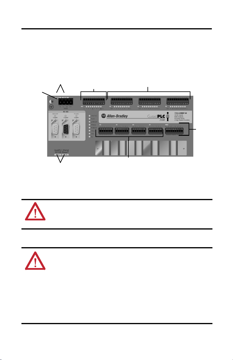
About the Controller
The GuardPLC 1800 controller is a programmable electronic system featuring 24 digital inputs,
8 digital outputs, 2 counters, 8 analog inputs, and 4 connections for GuardPLC Ethernet
communication.
Ethernet Ports
(on top of controller)
Voltage
Supply
Connection
Ethernet Ports (on bottom of controller)
Digital
Outputs
General Safety
ATTENTION: Personnel responsible for the application of safety-related
programmable electronic systems (PES) shall be aware of the safety
requirements in the application of the system and shall be trained in using the
system.
Prevent Electrostatic Discharge
Digital Inputs
High
Speed
Counter
Analog Inputs
ATTENTION: This equipment is sensitive to electrostatic discharge, which can
cause internal damage and affect normal operation. Follow these guidelines
when you handle this equipment:
• Touch a grounded object to discharge static potential.
• Wear an approved wrist-strap grounding device.
• Do not touch connectors or pins on component boards.
• Do not touch circuit components inside the equipment.
• Use a static-safe workstation, if available.
• Store the equipment in appropriate static-safe packaging when not in use.
Rockwell Automation Publication 1753-IN002C-EN-P - June 2010
Page 4

4 GuardPLC 1800 Controllers
Environment and Enclosure
ATTENTION: This equipment is intended for use in a Pollution Degree 2
industrial environment, in overvoltage Category II applications (as defined in
IEC publication 60664-1), at altitudes up to 2000 m (6562 ft) without derating.
This equipment is considered Group 1, Class A industrial equipment according
to IEC/CISPR 11. Without appropriate precautions, there may be difficulties
with electromagnetic compatibility in residential and other environments due
to conducted as well as radiated disturbances.
This equipment is supplied as open-type equipment. It must be mounted within
an enclosure that is suitably designed for those specific environmental
conditions that will be present and appropriately designed to prevent personal
injury resulting from accessibility to live parts. The enclosure must have
suitable flame-retardant properties to prevent or minimize the spread of flame,
complying with a flame spread rating of 5VA, V2, V1, V0 (or equivalent) if
non-metallic. The interior of the enclosure must be accessible only by the use
of a tool. Subsequent sections of this publication may contain additional
information regarding specific enclosure type ratings that are required to
comply with certain product safety certifications.
In addition to this publication, see:
• Industrial Automation Wiring and Grounding Guidelines, Rockwell
Automation publication 1770-4.1
• NEMA 250 and IEC 60529, as applicable, for explanations of the degrees of
protection provided by different types of enclosure.
, for additional installation requirements.
Install the Controller
Follow these steps to install the GuardPLC 1600 controller.
1. Mount the controller to a DIN rail.
2. Ground the controller.
3. Wire the controller.
4. Make communication connections.
This publication describes these steps in detail.
Rockwell Automation Publication 1753-IN002C-EN-P - June 2010
Page 5
Mount the Controller
GuardPLC 1800 Controllers 5
IMPORTANT
For effective cooling, mount the controller following these guidelines
• Mount the controller horizontally.
• Provide a gap of at least 100 mm (3.94 in.) above and below the controller.
• Select a location where air flows freely or use an additional fan.
• Do not mount the controller over a heating device.
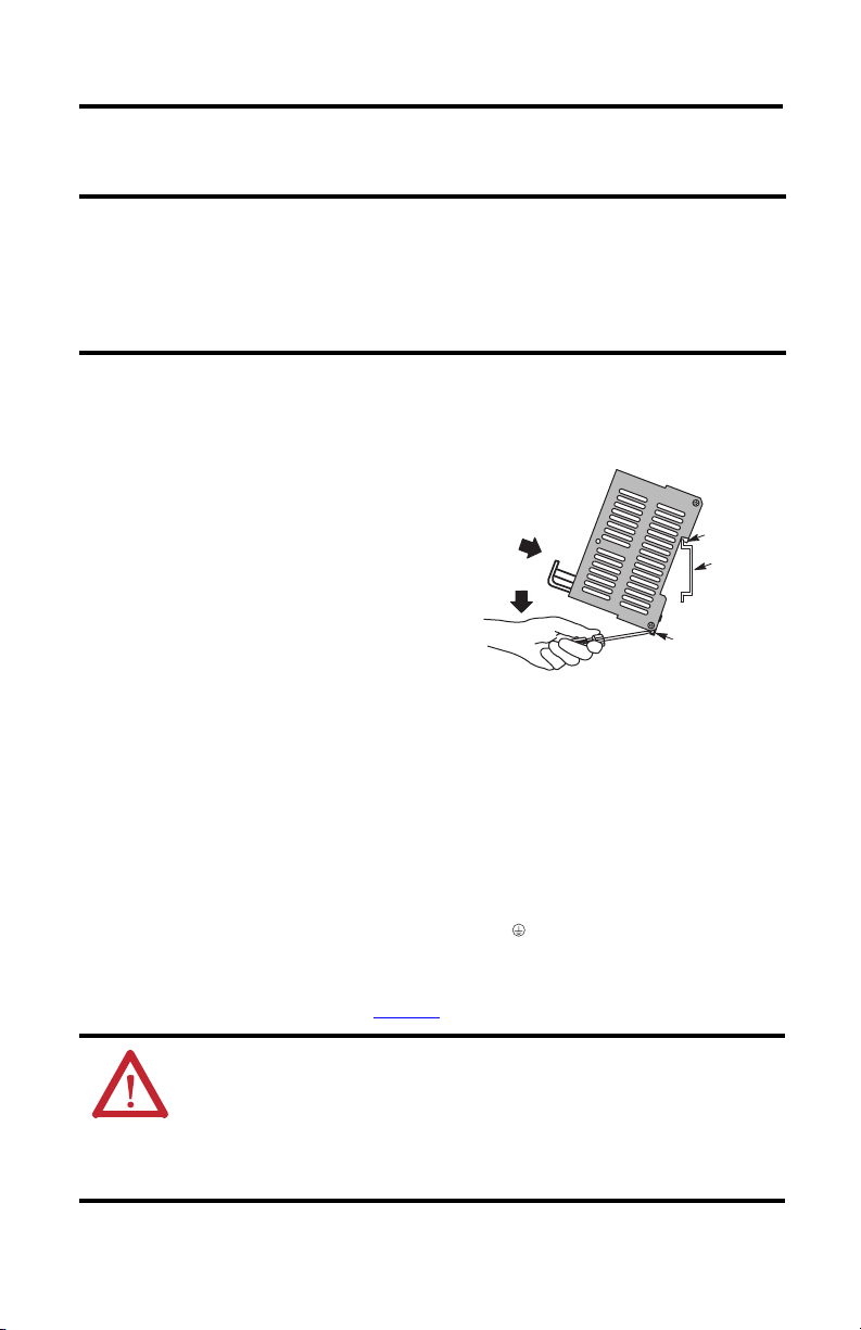
The controller cannot be panel-mounted. Mount the controller to a DIN rail by following these
steps.
1. Hook the top slot over the DIN rail.
2. Insert a flathead screwdriver into the gap
between the housing and the latch and pull
the latch downward.
3. Hold the latch down as you push the housing
back onto the DIN rail.
4. Release the latch to lock the device onto the
rail.
TIP
To remove the controller from the DIN rail, insert a flathead screwdriver
into the gap between the housing and the latch and pull the latch
downward as you lift the controller off of the rail.
(3)
(2)
(1) Top Slot
DIN Rail
Latch
Ground the Controller
The controller is functionally grounded through its DIN rail connection. A protective earth
ground connection is required and is provided through a separate grounding screw on the upper
left of the housing and marked with the grounding symbol .
You must also provide an acceptable grounding path for each device in your application. For
more information on proper grounding guidelines, refer to the Industrial Automation Wiring
and Grounding Guidelines, publication 1770-4.1
ATTENTION: This product is grounded through the DIN rail to chassis ground.
Use zinc-plated yellow-chromate steel DIN rail to assure proper grounding. The
use of other DIN rail materials (for example, aluminum or plastic) that can
corrode, oxidize, or are poor conductors, can result in improper or intermittent
grounding. Secure DIN rail to mounting surface approximately every 200 mm
(7.8 in.) and use end-anchors appropriately.
Rockwell Automation Publication 1753-IN002C-EN-P - June 2010
.
Page 6
6 GuardPLC 1800 Controllers
Wire the Controller
The following section describe how to connect the voltage supply and wire the controller’s
digital inputs and outputs.
Connect the Voltage Supply
The 24V DC voltage supply must feature galvanic isolation (in accordance with
EN 60950 or UL 1950) since inputs and outputs are not electrically isolated from the processor.
To comply with CE Low Voltage Directives (LVD) and UL restrictions, you must use either a
Safety Extra Low Voltage (SELV), or a Protected Extra Low Voltage (PELV) power supply to
power this controller. A SELV supply cannot exceed 30V rms, 42.4V peak, or 60V DC under
normal conditions and under single-fault conditions. A PELV supply has the same rating and is
connected to protected earth.
IMPORTANT
IMPORTANT
The supply voltage is connected via a 4-pin connector that accommodates wire sizes up to
2
(14 AWG). You need to connect only one wire to L+ and one wire to L-. Both L+ and
2.5 mm
L- terminals are internally connected, so you can daisy-chain 24V DC power from the
GuardPLC controller to other devices in the panel by using the remaining terminal.
Protect the controller with a slow-blowing fuse.
The GuardPLC 1800 controller can draw up to 9 A. The controller needs 1 A to
operate. Up to 8 A can be used to source voltage power for inputs and
outputs connected to the controller.
ATTENTION: Do not reverse the L+ and L- terminals or damage to the
controller will result. There is no reverse polarity protection.
Rockwell Automation Publication 1753-IN002C-EN-P - June 2010
Page 7
GuardPLC 1800 Controllers 7
Safety-Related Digital Inputs
The controller has 24 digital inputs whose status is indicated via status indicators when the
controller is in RUN mode.
LS+ is a voltage source that provides 24V DC for a group of eight dry contact inputs. There are
three groups on the GuardPLC 1800 controller.
COM
24V DC
Power
+
Supply
(—)4(—)
3
L-L- L+ L+
24V DC
RS-485
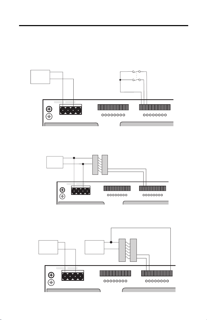
Connection of Voltage Supply to Input Device
If devices require 24V DC to operate and use the same power source as the controller, then wire
the outputs of the device directly to inputs on the controller.
COM
24V DC
Power
+
Supply
123456
1234
1L-
Light Curtain
(or any Safety Input)
COM
+
78910
56
345 678
11 12 13 14 15 16
11 12 13 14
10789
L-DO 2
(2A)(2A)
17 18 19 20
15 16
1LS+ L-DI 2 3 4 5 6 7 8
2017 18 19
(—)4(—)
3
L-L- L+ L+
24V DC
RS-485
123456
1234
1L-
3456 78
56
78910
(2A)(2A)
10789
L-DO 2
11 12 13 14 15 16
15 16
11 12 13 14
1LS+ L-DI 2 3 4 5 6 7 8
17 18 19 20
2017 18 19
Connection of Voltage Supply to Input Device
Devices with their own dedicated power supply can also be connected. Connect the reference
pole of the external power supply to the L- reference pole of the input.
Light Curtain
(or any Safety Input)
24V DC
Power
Supply
COM
+
(—)4(—)
3
L-L- L+ L+
24V DC
RS-485
24V DC
Power
Supply
COM
+
123456
1234
1L-
COM
+
78910
56
345 678
11 12 13 14 15 16
11 12 13 14
10789
L-DO 2
(2A)(2A)
17 18 19 20
15 16
1LS+ L-DI 2 3 4 5 6 7 8
2017 18 19
Connection of Devices with Dedicated Power Supplies
Rockwell Automation Publication 1753-IN002C-EN-P - June 2010
Page 8
8 GuardPLC 1800 Controllers
The safe state of an input is indicated by a 0 signal being passed to the user program logic. If the
test routines detect a fault in the digital inputs, a 0 signal is processed in the user program for the
defective channel. When a fault occurs, the inputs are switched off (0).
Follow the closed-circuit principle for external wiring when connecting sensors. To create a safe
state in the event of a fault, the input signals revert to the de-energized state (0). The FAULT
status indicator activates.
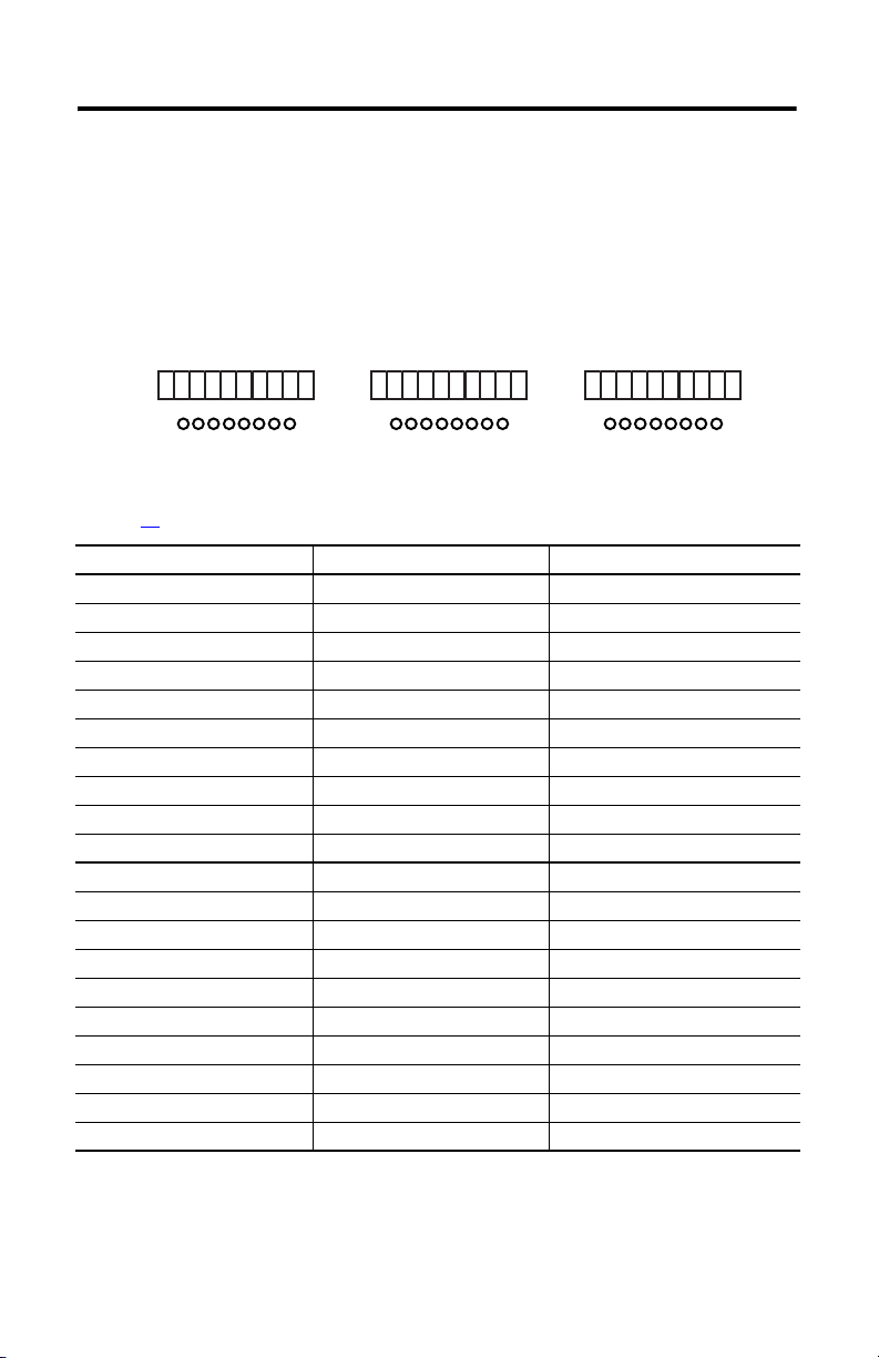
Digital Input Terminals
11 12 13 14 15 16
11 12 13 14
1LS+L-DI 2 3 4 5 6 7 8
Terminals accommodate wires up to 1.5 mm2 (16 AWG). See the terminal torque specifications
on page 21. Digital inputs are connected to these terminals.
Terminal Number Designation Function
11 LS+ Sensor supply for inputs 1…8
12 1 Digital input 1
13 2 Digital input 2
14 3 Digital input 3
15 4 Digital input 4
16 5 Digital input 5
17 6 Digital input 6
18 7 Digital input 7
19 8 Digital input 8
20 L- Reference pole
21 LS+ Sensor supply for inputs 9…16
22 9 Digital input 9
23 10 Digital input 10
24 11 Digital input 11
25 12 Digital input 12
26 13 Digital input 13
27 14 Digital input 14
28 15 Digital input 15
29 16 Digital input 16
30 L- Reference pole
15 16
17 18 19 20
21 22 23 24 25 26
2017 18 19
21 22 23 24
1LS+L-DI 2345678
25 26
27 28 29 30
31 32 33 34 35 36
3027 28 29
31 32 33 34
1LS+L-DI 2345678
35 36
37 38 39 40
4037 38 39
Rockwell Automation Publication 1753-IN002C-EN-P - June 2010
Page 9

GuardPLC 1800 Controllers 9
Terminal Number Designation Function
31 LS+ Sensor supply for inputs 17…24
32 17 Digital input 17
33 18 Digital input 18
34 19 Digital input 19
35 20 Digital input 20
36 21 Digital input 21
37 22 Digital input 22
38 23 Digital input 23
39 24 Digital input 24
40 L- Reference pole
LS+, not L+, should be used for short-circuit protection. Each LS+ features individual
short-circuit and EMC protection that make it important to use LS+ for only its eight related
inputs.
Line Control
The short-circuit and line break monitoring system, such as E-stop inputs, cannot be configured
for the GuardPLC 1800 controller. This is due to the fact that the 24 discrete inputs are actually
analog inputs with a resolution of one bit.
Safety-Related Analog Inputs
The controller has 8 analog inputs with transmitter supplies for the unipolar measurement of
voltages from 0…10V, referenced to L-. A 10 KΩ shunt is used for single-ended voltage signals.
With a 500 Ω shunt resistor, currents from 0…20 mA can also be measured.
The feeder lines should be no more than 300 m (984 ft) in length. Use shielded, twisted-pair
cables, with the shields connected at both ends, for each measurement input.
Unused analog inputs must be short-circuited. Place wire jumpers into any inputs that are not
used.
AI
T1 I1 L- T2 I2 L-
41 42 43 44 45 46
Wire Jumper
Rockwell Automation Publication 1753-IN002C-EN-P - June 2010
Wire Jumper
Page 10

10 GuardPLC 1800 Controllers
Analog Input Terminals
GuardPLC 1800 controller with a 4-wire device
Power
Power
External
+- +-
Single-ended
+- +-
Supply
voltage
Supply
External
current
Single-ended
10kΩ
AI
T1 I1 L- T2 I2 L-
500Ω
AI
T3 I3 L- T4 I4 L-
47 48 49 50 51 5241 42 43 44 45 46 53 54 55 56 57 58 59 60 61 62 63 64
AI
T1 I1 L- T2 I2 L-AIT3 I3 L- T4 I4 L-AIT5 I4 L- T6 I6 L-AIT7 I7 L- T8 I8 L-
AI
T5 I4 L- T6 I6 L-
47 48 49 50 51 5241 42 43 44 45 46 53 54 55 56 57 58 59 60 61 62 63 64
++-
-
4-wire Device with Power Source
from GuardPLC controller
24V DC
Power
Supply
+
COM
4-wire Device with External
Power Source
AI
T7 I7 L- T8 I8 L-
++-
-
Rockwell Automation Publication 1753-IN002C-EN-P - June 2010
Page 11

GuardPLC 1800 with a 2-wire Device
AI
T1 I1 L- T2 I2 L-AIT3 I3 L- T4 I4 L-AIT5 I4 L- T6 I6 L-AIT7 I7 L- T8 I8 L-
GuardPLC 1800 Controllers 11
47 48 49 50 51 5241 42 43 44 45 46 53 54 55 56 57 58 59 60 61 62 63 64
-
+
24V DC
Power
Supply
2-wire Device with Power Source
from GuardPLC controller
Terminals accommodate wires up to 1.5 mm
2-wire Device with External
2
(16 AWG). The analog inputs are connected to
these terminals.
Terminal Number Designation Function
41 T1 Transmitter supply 1
42 I1 Analog input 1
43 L- Reference pole
44 T2 Transmitter supply 2
45 I2 Analog input 2
46 L- Reference pole
47 T3 Transmitter supply 3
48 I3 Analog input 3
49 L- Reference pole
50 T4 Transmitter supply 4
51 I4 Analog input 4
52 L- Reference pole
53 T5 Transmitter supply 5
54 I5 Analog input 5
55 L- Reference pole
56 T6 Transmitter supply 6
57 I6 Analog input 6
58 L- Reference pole
+
COM
Power Source
-
+
Rockwell Automation Publication 1753-IN002C-EN-P - June 2010
Page 12
12 GuardPLC 1800 Controllers
47 48 49 50 51 5241 42 43 44 45 46 53 5
Terminal Number Designation Function
59 T7 Transmitter supply 7
60 I7 Analog input 7
61 L- Reference pole
62 T8 Transmitter supply 8
63 I8 Analog input 8
64 L- Reference pole
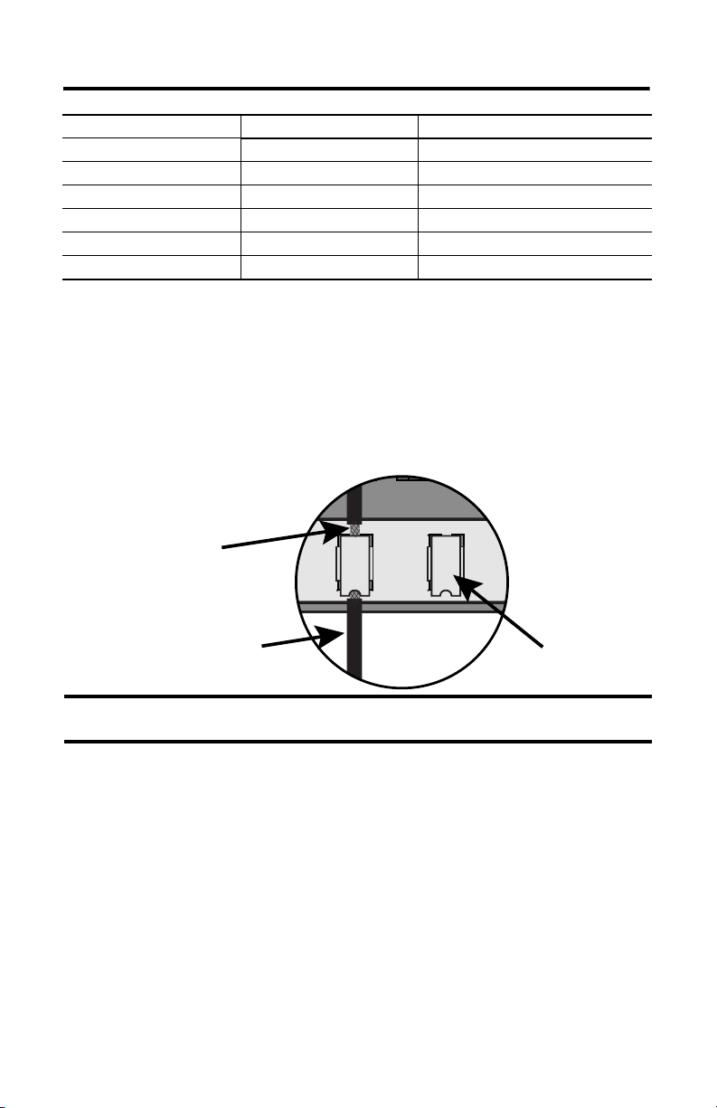
Connecting the I/O Circuits
The I/O circuits are connected to the front plate of the controller using pluggable terminals. For
controls with analog inputs, shielded cabling is fed in from below so that the shielding can be
connected to the shield contact plate using a clip. Remove about 2 cm (0.78 in.) of the outer
cable insulation so that the mesh is exposed at the point where the cable is clipped to the plate.
Position the clip over the uninsulated cable shielding and push it into the slots of the shield
contact plate until it fits firmly in place, as shown below.
Mesh
IMPORTANT
Shielded Cable
Make sure that the mesh comes in direct contact with the shield contact plate.
Cable Clip
If the mesh does not touch the plate, the cable is not grounded.
Safety-related Digital Outputs
The controller has eight digital outputs (DO1…DO8) whose status is indicated via status
indicators.
An output is in a safe state when it is de-energized. When a fault occurs, all outputs are switched
off.
Outputs 1…3 and 5…7 can have a load of 0.5 A at an ambient temperature of 60 °C (140 °F).
Outputs 4 and 8 can each have a load of 1 A at an ambient temperature of 60 °C (140 °F), or up
to 2 A at an ambient temperature of 50 °C (122 °F).
With an overload, one or all of the outputs are turned off. When the overload is eliminated, the
outputs are activated again according to the specified value.
Although the external line of an output is not monitored, a short-circuit will be indicated.
Rockwell Automation Publication 1753-IN002C-EN-P - June 2010
Page 13
Digital Output Terminals
123456
GuardPLC 1800 Controllers 13
78910
1234
1L- L-DO 2
56
345 678
(2A)(2A)
10789
Terminals accommodate wires up to 1.5 mm2 (16 AWG). See the terminal torque specifications
on page 21. Digital outputs are connected to these terminals.
Terminal Number Designation Function Current
1 L- Reference pole —
2 1 Digital output 1 0.5 A
3 2 Digital output 2 0.5 A
4 3 Digital output 3 0.5 A
5 4 Digital output 4 (for increased load) 2.0 A
6 5 Digital output 5 0.5 A
7 6 Digital output 6 0.5 A
8 7 Digital output 7 0.5 A
9 8 Digital output 8 (for increased load) 2.0 A
10 L- Reference pole —
For connection of a load, the reference pole L- of the concerned channel group must be used
(2-pole connection). Although L- at terminals 1 and 6, 7 and 12 is connected internally to L- on
he power supply input, it is strictly recommended to use 1 and 6 for outputs 1…4 only and 7 and
12 for outputs 5…8 only. EMC testing was performed in this manner.
Rockwell Automation Publication 1753-IN002C-EN-P - June 2010
Page 14

14 GuardPLC 1800 Controllers
63 64 65 66 67 68 71 7269 70
net
Example: Connecting Actuators to the Outputs
DO 2
…
DO 1
DO 7
DO 8L-L-
TIP
Inductive loads can be connected without a protection diode on the load.
However, Rockwell Automation strongly recommends that a protection diode be
fitted directly to the load to suppress any interference voltage. A 1N4004 diode
is recommended.
High-speed Counter Connections
The controller features two independent high-speed counters. Both counters are 24-bit, are
configured for either 5V or 24V DC, and have a maximum input frequency of 100 KHz.
The counters can be used as a counter or as a decoder for 3-bit Gray Code inputs. As a counter,
input A is the counter input, input B is the counter direction input, and input Z is used for a
reset.
The counter inputs must be connected using shielded, twisted-pair cables for each measurement
input. The shields must be connected at both ends. The input lines should be no more than
500 m (1640 ft) in length. All L- connections are internally connected on the controller.
Cables are clipped to the shield contact plate when connecting counter inputs. Remove about
2 cm (0.78 in.) of the outer cable insulation so that the mesh is exposed at the point where the
cable is clipped to the plate.
Mesh
Shield
Contact Plate
IMPORTANT
Rockwell Automation Publication 1753-IN002C-EN-P - June 2010
Cable Clip
Make sure that the mesh comes in direct contact with the shield contact plate.
If the mesh does not touch the plate, the cable is not grounded.
Page 15
GuardPLC 1800 Controllers 15
High-speed Counter Terminals
HSC
A1 B1 Z1 L- A2 B2 Z2 L-
65 66 67 68 71 7269 70
Terminals accommodate wires up to 1.5 mm2 (16 AWG). Counters are connected to these
terminals.
Terminal Number Designation Counter Function Gray Code Function
65 A1 Input A1 bit 0 (LSB)
66 B1 Input B1 bit 1
67 Z1 Input Z1 bit 2 (MSB)
68 L- Common reference pole
69 A2 Input A2 bit 0 (LSB)
70 B2 Input B2 bit 1
71 Z2 Input Z2 bit 2 (MSB)
72 L- Common reference pole
IMPORTANT
D
TIP
Do not terminate unused inputs.
For more information on GuardPLC system wiring and counter
configuration, see the GuardPLC Controller Systems User Manual,
publication 1753-UM001.
Make Communication Connections
The controller supports separate connections for safety and nonsafety-related communication.
Connections for Safety-related Communication
The controller has four 10/100BaseT, RJ45 connectors to provide communication via
GuardPLC Ethernet protocol to distributed I/O and other GuardPLC controllers, OLE for
Process Control (OPC) servers, and with the programming software. Connectors 1 and 2 are on
the bottom side on the left. Connectors 3 and 4 are on the top side on the left. All four
connectors and the GuardPLC processor are connected together by an internal Ethernet switch.
The switches are auto-detect. Either crossover or straight-through Ethernet cabling can be used.
Star or line configurations are available. Make sure that a network loop is not generated. Data
packets must be able to reach a node only via a single path.
Rockwell Automation Publication 1753-IN002C-EN-P - June 2010
Page 16

16 GuardPLC 1800 Controllers
OPC Server
The GuardPLC 1800 controller is an OPC client. An OPC server, catalog number 1753-OPC,
is available from Rockwell Automation and lets computer applications read and write data to and
from the GuardPLC controller.
MAC Address
The media access control (MAC) address of the controller can be found on the label positioned
over both lower RJ45 connections.
Connections for Nonsafety-Related Communication
Three 9-pin D-shell connectors on the front of the controller provide the following
communication options.
Designation Function
COMM1 (RS-485) Modbus Slave (1753-L32BBB-M)
COMM2 TBD
COMM3 (RS-485) GuardPLC ASCII Protocol
The pin assignments of the D-shell connector are listed in this table.
Profibus-DP-Slave (1753-L32BBB-P)
Connection Signal Function
1——
2 RP 5V, decoupled with diodes
3 RxD/TxD-A Receive/transmit data A
4 CNTR-A Control signal A
5 DGND Data reference potential
6 VP 5V, positive pole of supply voltage
7——
8 RxD/TxD-B Receive/transmit data B
9 CNTR-B Control signal B
IP Address and System ID (SRS)
A transparent label provided with the controller can be used to note the IP Address and system
ID (SRS). The default value for the IP Address is 192.168.0.99. The default SRS is 60000.
IMPORTANT
Rockwell Automation Publication 1753-IN002C-EN-P - June 2010
If you attach the label to the controller, make sure you do not cover any of the
ventilation slots.
Page 17

GuardPLC 1800 Controllers 17
Reset Push Button
The controller is equipped with a reset push button. Reset via the push button is necessary under
the following conditions.
• You forget the password to go online via the programming software.
• You are unable to determine the IP address and SRS of the controller.
The push button is accessible through a small round hole at the top of the housing,
approximately 4…5 cm (1.6…2.0 in.) from the left rim and recessed approximately 9.5 mm
(0.375 in.).
IMPORTANT
To reset, press and hold the push button for 20 seconds while rebooting the device by cycling
power. Pressing the Reset push button during operation has no affect.
With activation of the reset button:
Activate the reset push button using an insulated pin to prevent short-circuits.
• all accounts are deleted except for the default account.
• IP Address and System ID (SRS) are set to their default values.
The next time you cycle power, these settings will be restored to the last values stored into
nonvolatile memory. This means that either the settings prior to the reset will be restored, or if
any settings were changed after the reset, those new settings will still be in effect.
Rockwell Automation Publication 1753-IN002C-EN-P - June 2010
Page 18

18 GuardPLC 1800 Controllers
Controller Tests
In addition to the tests for safety, the controller tests the supply voltage and controller
temperature.
Supply Voltage Tests
The supply voltage (24V DC) is monitored and the alarm and system shutdown are controlled
according to the voltage levels listed below.
Voltage Level System Condition
19.3 to 28.8V Normal
< 19.3V Alarm state 1 (internal variables are written)
< 15.4V Alarm state 2 (prepares for shutdown)
< 13.0V Switched off
Temperature Tests
The temperature of the controller is automatically and continuously monitored. The alarm is
triggered by the temperature conditions described in the table below.
Operating Temperature Alarm
< 60 °C (140 °F) None (normal)
60…70 °C (140…158 °F) Warning on
> 70 °C (158 °F) Main alarm on
return to 64… 54 °C (147.2…129.2 °F) Main alarm off, warning on
return to < 54 °C (129.2 °F) None (return to normal)
Rockwell Automation Publication 1753-IN002C-EN-P - June 2010
Page 19

GuardPLC 1800 Controllers 19
Status Indicators
Indicator State Description
24V DC On 24V DC operating voltage present.
Off No operating voltage.
RUN On This is the normal status of the controller.
Flashing The controller is in STOP mode and is not executing a routine.
Off The controller is in ERROR_STOP mode (see ERROR).
ERROR On
Off No errors are detected.
PROGress On The upload of a new controller configuration is in progress.
Flashing The upload of a new operating system into the nonvolatile ROM is in progress.
Off No upload of controller configuration or operating system in progress.
FORCE On The controller is executing a routine (RUN) and FORCE mode is activated by the user.
Flashing The controller is in STOP mode, but Forcing has been initiated and will be activated
Off Forcing is OFF.
FAULT On
Flashing An error has occurred during a nonvolatile ROM write cycle.
Off None of the above errors has occurred.
OSL Flashing Emergency Operating System Loader is active.
BL Flashing Boot Loader unable to load operating system or unable to start COMM operating
Controller status can be interrogated through the programming software. For more information, see the
GuardPLC Controller System User Manual, publication 1753-UM001
A routine, which has been loaded into the controller, is executed.
The controller processes input and output signals, carries out communication, and
performs hardware and software tests.
All system outputs are reset.
STOP mode can be triggered by setting the Emergency stop system variable to TRUE
in the routine, or by direct command from the programming software.
• A hardware error has been detected by the controller. The controller goes to
ERROR_STOP mode and the execution of the routine is halted. Hardware errors
are errors in the controller, errors in one or more of the digital input and output
modules, or errors in the counters.
• A software error in the operating system has been detected by the controller.
• The watchdog has reported an error due to exceeded cycle time.
All system outputs will be reset and the controller ceases all hardware and software
tests. The controller can only be restarted by a command from the programming
software.
when the controller is started.
• The routine (logic) has caused an error.
• The controller configuration is faulty.
• The upload of a new operating system was not successful, and the operating
system is corrupted.
One or more I/O errors have occurred.
system loader.
.
Rockwell Automation Publication 1753-IN002C-EN-P - June 2010
Page 20

20 GuardPLC 1800 Controllers
Communication via GuardPLC Ethernet is indicated by two small status indicators integrated
into all connecting sockets.
Indicator State Description
Green On Full-duplex operation
Flashing Collision
Off Half-duplex operation, no collision
Yellow On Connection established
Flashing Interface activity
Additional nonsafety-related communication occurs on the field buses and is indicated by the
status indicators.
Indicator Connection Description
Green COMM 1 RS-485 interface, field bus active
COMM 2 Unassigned
COMM 3 Unassigned
Specifications
Technical Specifications – GuardPLC 1800 Controllers
Attribute 1753-L28BBBM-8A, 1753-L28BBBP-8A
User memory 250 KB max user program memory
250 KB max application data memory
Watchdog time, min 10 ms
Safety time, min 20 ms
Current consumption 9 A max (with max load)
Operating voltage 24V DC, -15…20%, w
Isolation voltage 50V (continuous), Basic Insulation Type, I/O to Ethernet and Ethernet to DC
Wiring category
Wire size
(1)
0.75 A idle current
≤ 15% (from a power supply with protective
separation conforming to IEC 61131-2 requirements)
power
Category 2 on communication ports, signal ports, and power ports
• I/O – 0.13…1.3 mm
75 °C (167 °F) or greater with 1.2 mm (3/64 in.) insulation max
• Power – 0.33…2.1 mm
at 75 °C (167 °F) or greater with 1.2 mm (3/64 in.) insulation max
ss
2
(26…16 AWG) solid or stranded copper wire rated at
2
(22…14 AWG) solid or stranded copper wire rated
• Ethernet – RJ45 connector according to IEC 60603-7, 2 or 4-pair Category
5e minimum cable according to TIA 568-B.1, or Category 5 cable according
to ISO/IEC 24702
• Comm: 9-pin D-sub
Rockwell Automation Publication 1753-IN002C-EN-P - June 2010
Page 21

GuardPLC 1800 Controllers 21
Technical Specifications – GuardPLC 1800 Controllers
Wire type Shielded on Ethernet, analog, and high-speed counter inputs
Terminal block torque 0.51 N•m (4.5 lb•in)
Fuse (external) 24V DC power: 10 A (time-lag)
Enclosure type rating Meets IP20
Width, approx. 257 mm (10.1 in.) including housing screws
Height, approx. 114 mm (4.49 in.) including latch
Depth, approx. 66 mm (2.60 in.) including grounding bolt
Weight, approx. 1.2 kg (2.64 lb)
Digital Inputs
Number of inputs 24 (not electrically isolated)
On state Voltage: 15…30V DC
Off state Voltage: 5V DC max
Input resistance < 7 kΩ
Overvoltage protection -10V, +35V
Line length, max 300 m (9.8 ft)
Supply 20V / 100 mA, short-circuit proof
Digital Outputs
Number of outputs 8 (not electrically isolated)
Output voltage range ≥ L+ minus 2V
Output current Channels 1…3 and 5…7: 0.5 A @ 60 °C (140 °F)
Surge current per channel 1 A for 10ms @ 1Hz (channels 1…3 and 5…7)
Current load, min 2 mA per channel
Internal voltage drop 2.0V DC max @ 2 A
Off-state leakage current 1 mA max @ 2V
Total output current 7 A max
Current consumption: approximately 3.5 mA @ 24V DC
Current consumption: approximately 4.5 mA @ 30V DC
Current consumption: 1.5 mA max (1 mA @ 5V DC)
Channels 4 and 8: 1A @ 60 °C (140 °F); 2A @ 50 °C (122 °C)
4 A for 10ms @ 1Hz (channels 4 and 8)
Rockwell Automation Publication 1753-IN002C-EN-P - June 2010
Page 22

22 GuardPLC 1800 Controllers
Technical Specifications – GuardPLC 1800 Controllers
Counters
Number of counters 2 (not electrically isolated)
Inputs 3 per counter (A, B, Z)
Input voltages 5V and 24V DC
High signal (5V DC): 4…6V
High signal (24V DC): 13…33V
Low signal (5V DC): 0…0.5V
Low signal (24V DC): -3…5V
Input currents 1.4 mA @ 5V DC
Input impedance 3.7 kΩ
Counter resolution 24-bit
Input frequency, max 100 kHz
Triggered on negative edge
Edge steepness 1 V/μs
Pulse duty factor 1:1
Analog Inputs
Number of inputs 8 (unipolar, not electrically isolated)
External shunt
(for current measurement)
Input values related to L- Nominal Value: 0…10V DC or 0…20 mA with 500 Ω shunt
Input impedance 1 MΩ
Internal resistance of the
signal source
Overvoltage protection +15V, -4V
Resolution (A/D converter) 12-bit
Accuracy 0.1% @ 25 °C (77 °F)
Transmitter supplies 25.37…28.24V / ≤ 46 mA, short-circuit proof
Safety accuracy ± 2%
(1) Use this Conductor Category information for planning conductor routing. Refer to Industrial Automation Wiring and
Grounding Guidelines, publication 1770-4.1
6.5 mA @ 24V DC
500 Ω for 0…20 mA
Service Value: -0.1…11.5V DC or -0.4…23 mA with 500 Ω shunt
≤ 500 Ω
0.5% @ 60 °C (140 °F)
.
Rockwell Automation Publication 1753-IN002C-EN-P - June 2010
Page 23

GuardPLC 1800 Controllers 23
Environmental Specifications – GuardPLC 1800 Controllers
Attribute 1753-L28BBB-M, 1753-L28BBB-P
Temperature, nonoperating
• IEC 60068-2-1 (Test Ab, Unpackaged nonoperating
cold)
• IEC 60068-2-2 (Test Bb, Unpackaged nonoperating
dry heat)
• IEC 60068-2-14 (Test Na, Unpackaged nonoperating
thermal shock)
Temperature, operating
• IEC 60068-2-1 (Test Ad, operating cold)
• IEC 60068-2-2 (Test Bd, operating dry heat)
• IEC 60068-2-14 (Test Nb, operating thermal shock)
Temperature, surrounding air 60 °C (140 °F)
Vibration
• IEC 60068-2-6 (Test Fc, operating)
Shock, operating
-40…85 °C (-40…185 °F)
0…60 °C (32…140 °F)
1 g @ 10…150 Hz
15 g
• IEC 60068-2-27 (Test Ea, unpackaged shock)
Relative humidity
10…95% noncondensing
• IEC 60068-2-30 (Test Db, unpackaged damp heat)
Emissions CISPR 11: Group 1, Class A
ESD Immunity
• IEC 61000-4-2
Radiated RF Immunity
• IEC 61000-4-3
• 6 kV contact discharges
• 8 kV air discharges
• 10V/m with 1kHz sine-wave 80% AM from 80
MHz…2000 MHz
• 1 V/m with 1 kHz sine-wave 80% AM from
2000…2700 MHz
EFT/B Immunity
• IEC 61000-4-4
• ±2 kV @ 5 kHz on DC power ports
• ±1 kV @ 5 kHz on signal ports
• ±1 kV @ 5 kHz on communication ports
Surge Transient Immunity
• IEC 61000-4-5
• ±500V line-line (DM) and ±500V line-earth (CM) on
DC power ports
• ±1 kV line-earth (CM) on signal ports
• ±1 kV line-earth (CM) on communication ports
Conducted RF Immunity
• IEC 61000-4-6
Damped Oscillatory Wave Immunity
• IEC 61000-4-12
10V rms with 1 kHz sine-wave 80% AM from 150
kHz…80 MHz
• ±1 kV line-earth (CM) on signal ports
• ±1 kV line-earth (CM) on power ports
Rockwell Automation Publication 1753-IN002C-EN-P - June 2010
Page 24

Certifications
Certification (when
product is marked)
c-UL-us UL Listed Industrial Control Equipment, certified for US and Canada. See UL
CE European Union 2004/108/EC EMC Directive, compliant with:
1753-L28BBBM-8A, 1753-L28BBBP-8A
(1)
File E65584.
• EN 61326-1 Meas./Control/Lab., Industrial Requirements
• EN 61000-6.2; Industrial Immunity
• EN 61000-6-4; Industrial Emissions
• EN 61131-2; Programmable Controllers (Clause 8, Zone A & B)
C-Tick Australian Radiocommunications Act, compliant with: AS/NZS CISPR 11;
Functional Safety Certified by TÜV
(1) See the Product Certification link at http://www.ab.com for Declarations of Conformity, Certificates, and other certification
details.
(2) When used with specified firmware revisions.
Industrial Emissions
(Cat. 4) according to ISO 13849-1
(2)
: up to and including SIL 3 according to IEC 61508 and PLe
Additional Resources
The table below provides a listing of publications that contain important information about
GuardPLC systems.
Resource Description
GuardPLC Controller Systems Safety Reference
Manual, publication 1753-RM002
GuardPLC Controller Systems User Manual,
publication 1753-UM001
Using RSLogix Guard PLUS! Software with
GuardPLC Controllers Programming Manual,
publication 1753-PM001
Industrial Automation Wiring and Grounding
Guidelines, publication 1770-4.1
You can view or download publications at http://www.rockwellautomation.com/literature
order paper copies of technical documentation, contact your local Rockwell Automation
distributor or sales representative.
Detailed information regarding the safety certification of the
GuardPLC System
Detailed information on installing, wiring, configuring,
operating, maintaining, and troubleshooting GuardPLC
systems
Detailed information on programming your GuardPLC system
using RSLogix Guard PLUS! software
General guidelines for installing a Rockwell Automation
industrial system
. To
Allen-Bradley, Rockwell Software, Rockwell Automation, and GuardPLC are trademarks of Rockwell Automation, Inc.
Trademarks not belonging to Rockwell Automation are property of their respective companies.
Rockwell Otomasyon Ticaret A.Ş., Kar Plaza İş Merkezi E Blok Kat:6 34752 İçerenköy, İstanbul, Tel : +90 (216) 5698400
Rockwell Automation Publication 1753-IN002C-EN-P - June 2010 PN-77077
Supersedes Publication 1753-IN002B-EN-P - March 2004 Copyright © 2010 Rockwell Automation, Inc. All rights reserved. Printed in the U.S.A.
 Loading...