

Page 1

Installation Instructions
GuardPLC 1753-IF8XOF4 Analog I/O Module
Catalog Number 1753-IF8XOF4
Inside ................................................................................................page
Related Documentation ............................................................................3
Description................................................................................................4
General Safety..........................................................................................4
Mount the Module....................................................................................6
Wire the Module....................................................................................... 7
Reset Pushbutton....................................................................................14
Troubleshoot with LED Indicators...........................................................15
Specifications .........................................................................................16
Publication 1753-IN013A-EN-P - September 2005
Page 2
2 GuardPLC 1753-IF8XOF4 Analog I/O Module
Important User Information
Solid state equipment has operational characteristics differing from those of electromechanical equipment.
Safety Guidelines for the Application, Installation and Maintenance of Solid State Controls (Publication
SGI-1.1 available from your local Rockwell Automation sales office or online at
http://www.ab.com/manuals/gi) describes some important differences between solid state equipment and
hard-wired electromechanical devices. Because of this difference, and also because of the wide variety of
uses for solid state equipment, all persons responsible for applying this equipment must satisfy themselves
that each intended application of this equipment is acceptable.
In no event will Rockwell Automation, Inc. be responsible or liable for indirect or consequential damages
resulting from the use or application of this equipment.
The examples and diagrams in this manual are included solely for illustrative purposes. Because of the many
variables and requirements associated with any particular installation, Rockwell Automation, Inc. cannot
assume responsibility or liability for actual use based on the examples and diagrams.
No patent liability is assumed by Rockwell Automation, Inc. with respect to use of information, circuits,
equipment, or software described in this manual.
Reproduction of the contents of this manual, in whole or in part, without written permission of Rockwell
Automation, Inc. is prohibited.
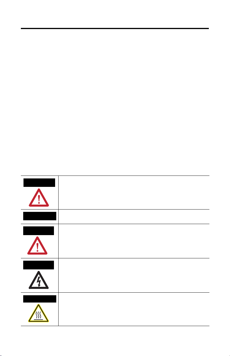
Throughout this manual, when necessary we use notes to make you aware of safety considerations.
WARNING
Identifies information about practices or circumstances that can cause an explosion in a
hazardous environment, which may lead to personal injury or death, property damage,
or economic loss.
IMPORTANT
ATTENTION
SHOCK HAZARD
BURN HAZARD
Identifies information that is critical for successful application and understanding of the
product.
Identifies information about practices or circumstances that can lead to personal injury
or death, property damage, or economic loss. Attentions help you:
• identify a hazard
• avoid a hazard
• recognize the consequence
Labels may be located on or inside the equipment (e.g., drive or motor) to alert people
that dangerous voltage may be present.
Labels may be located on or inside the equipment (e.g., drive or motor) to alert people
that surfaces may be dangerous temperatures.
Publication 1753-IN013A-EN-P - September 2005
Page 3
GuardPLC 1753-IF8XOF4 Analog I/O Module 3
Related Documentation
The table below provides a listing of publications that contain important
information about GuardPLC Controller systems.
For Read this document Publication
number
Detailed information regarding the safety certification
of the GuardPLC System.
Detailed information on installing, wiring, configuring,
operating, maintaining, and troubleshooting GuardPLC
systems.
Information on programming with RSLogix Guard PLUS!
software
Information on installing GuardPLC 1600 controllers GuardPLC 1600 Controller
Information on installing GuardPLC 1800 controllers GuardPLC 1800 Controller
Information on installing GuardPLC 1753-IB20XOB8
Digital Input/Output Modules
Information on installing GuardPLC 1753-IB16 Digital
Input Modules
Information on installing GuardPLC 1753-OB16 Digital
Output Modules
Information on installing GuardPLC 1753-IB8XOB8
Digital Input/Output Modules
Information on installing GuardPLC 1753-IB16XOB8
Digital Input/Output Modules
Information on installing GuardPLC 1753-OW8 Relay
Output Modules
GuardPLC Controller Systems
Safety Reference Manual
GuardPLC Controller Systems User
Manual
Using RSLogix Guard PLUS!
Software with GuardPLC
Controllers
Installation Instructions
Installation Instructions
GuardPLC Digital Input/Output
Module
GuardPLC Digital Input Module
Installation Instructions
GuardPLC Digital Output Module
Installation Instructions
GuardPLC 8-Digital Inputs and
8-Digital Outputs Module
Installation Instructions
GuardPLC16-Digital Inputs and
8-Digital Outputs Module
Installation Instructions
GuardPLC 8-Relay Output Module
Installation Instructions
1753-RM002
1753-UM001
1753-PM001
1753-IN001
1753-IN002
1753-IN003
1753-IN004
1753-IN005
1753-IN010
1753-IN011
1753-IN012
If you would like a manual, you can:
• download a free electronic version from the internet at
www.rockwellautomation.com/literature
• purchase a printed manual by contacting your local distributor or Rockwell
Automation representative)
IMPORTANT
For planning information, see the Industrial Automation Wiring
and Grounding Guidelines, publication 1770-4.1.
Publication 1753-IN013A-EN-P - September 2005
Page 4
4 GuardPLC 1753-IF8XOF4 Analog I/O Module
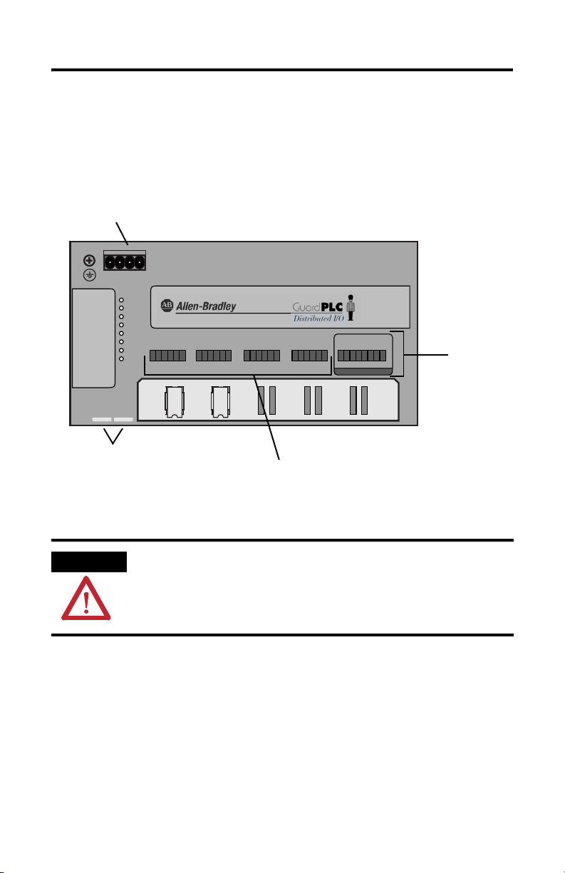
Description
The 1753-IF8XOF4 module is a distributed safety I/O module for use with
GuardPLC controllers. The module features 8 safety analog inputs and 4 standard
analog outputs. The module communicates with the GuardPLC controller via
GuardPLC Ethernet.
Voltage Supply Connection
L-L- L+ L+
24V DC
GuardPLC Ethernet
10/100 BaseT
<—>2<—>
1
24 V DC
RUN
ERROR
PROG
FORCE
AI
FAULT
T1 I1 L- T2 I2 L-AIT3 I3 L- T4 I4 L-AIT5 I5 L- T6 I6 L-AIT7 I7 L- T8 I8 L-
OSL
BL
1 2 34 56 7 8 9101112 13 1415161718 192021222324
1753-IF8XOF4
8 Analog Inputs
4 Analog Outputs
AO
O1 O2 O3 O4
+-+-+-+-
25 26 27 28 29 30 31 32
STD ANALOG OUTPUTS
Standard
Analog
Outputs
Ethernet Ports
(on bottom of controller)
Safety Analog Inputs
General Safety
ATTENTION
Publication 1753-IN013A-EN-P - September 2005
Personnel responsible for the application of safety-related
Programmable Electronic Systems (PES) shall be aware of the
safety requirements in the application of the system and shall be
trained in using the system.
Page 5
GuardPLC 1753-IF8XOF4 Analog I/O Module 5
Open style devices must be provided with environmental and safety protection by
proper mounting in enclosures designed for specific application conditions.
ATTENTION
Environment and Enclosure
This equipment is intended for use in a Pollution Degree 2 industrial environment, in
overvoltage Category II applications (as defined in IEC publication 60664-1), at altitudes up to
2000 meters without derating.
This equipment is considered Group 1, Class A industrial equipment according to IEC/CISPR
Publication 11. Without appropriate precautions, there may be potential difficulties ensuring
electromagnetic compatibility in other environments due to conducted as well as radiated
disturbance.
This equipment is supplied as "open type" equipment. It must be mounted within an
enclosure that is suitably designed for those specific environmental conditions that will be
present and appropriately designed to prevent personal injury resulting from accessibility to
live parts. The interior of the enclosure must be accessible only by the use of a tool.
Subsequent sections of this publication may contain additional information regarding
specific enclosure type ratings that are required to comply with certain product safety
certifications.
See NEMA Standards publication 250 and IEC publication 60529, as applicable, for
explanations of the degrees of protection provided by different types of enclosure. Also, see
the appropriate sections in this publication, as well as the Allen-Bradley publication 1770-4.1
("Industrial Automation Wiring and Grounding Guidelines"), for additional installation
requirements pertaining to this equipment.
Preventing Electrostatic Discharge
ATTENTION
This equipment is sensitive to electrostatic discharge, which can
cause internal damage and affect normal operation. Follow these
guidelines when you handle this equipment:
• Touch a grounded object to discharge static potential.
• Wear an approved wrist-strap grounding device.
• Do not touch connectors or pins on component boards.
• Do not touch circuit components inside the equipment.
• If available, use a static-safe workstation.
• When not in use, store the equipment in appropriate static
safe packaging.
Publication 1753-IN013A-EN-P - September 2005
Page 6
6 GuardPLC 1753-IF8XOF4 Analog I/O Module
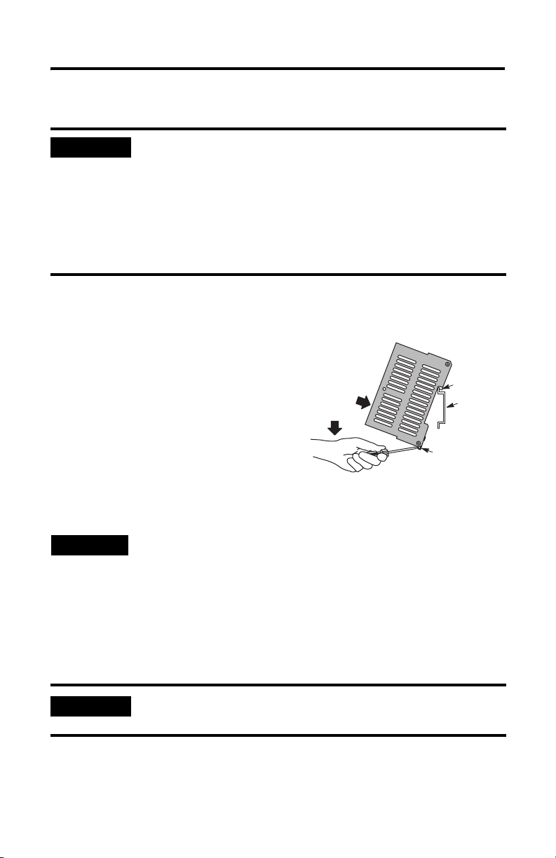
Mount the Module
IMPORTANT
The module cannot be panel-mounted. Mount the module to a DIN rail by
following the steps below.
1. Hook the top slot over the DIN rail.
2. Insert a flathead screwdriver into the
gap between the housing and the latch
and pull the latch downward.
3. Hold the latch down as you push the
housing back onto the DIN rail.
4. Release the latch to lock the module
onto the rail.
TIP
For effective cooling:
• Mount the module horizontally.
• Provide a gap of at least 100 mm (3.94 in.) above and below
the module.
• Select a location where air flows freely or use an additional
fan.
• Do not mount the module over a heating device.
(3)
(2)
Latch
To remove the module from the DIN rail, insert a flathead
screwdriver into the gap between the housing and the latch and
pull the latch downward as you lift the module off of the rail.
(1) Top Slot
DIN Rail
IP Address Label
A transparent label shipped with the module can be used to note the IP address
and system ID (SRS).
IMPORTANT
Publication 1753-IN013A-EN-P - September 2005
If you attach the label to the module, make sure you do not cover
any of the ventilation slots.
Page 7
GuardPLC 1753-IF8XOF4 Analog I/O Module 7
Wire the Module
Ground the Module
You must provide an acceptable grounding path for each device in your
application. For more information on proper grounding guidelines, refer to the
Industrial Automation Wiring and Grounding Guidelines, publication number
1770-4.1.
The I/O module is functionally grounded through its DIN rail connection. A
protective earth ground connection is required and is provided by a separate
grounding screw, located on the upper left of the housing and marked with the
grounding symbol .
ATTENTION
This product is grounded through the DIN rail to chassis ground.
Use zinc plated yellow-chromate steel DIN rail to assure proper
grounding. The use of other DIN rail materials (e.g. aluminum,
plastic, etc.) that can corrode, oxidize, or are poor conductors,
can result in improper or intermittent grounding.
Connections for Safety-Related Communications
Ethernet Switch
The module has two 10/100BaseT, RJ-45 connectors, located on the bottom of the
unit, that provide communications to the GuardPLC controller via GuardPLC
Ethernet. Because this is an Ethernet switch, you can daisy-chain connections from
the GuardPLC to other distributed I/O blocks. The switch is auto-detect. Either
cross-over or straight-through shielded Ethernet cabling can be used.
Star or line configurations are available. Make sure that a network loop is not
generated. Data packets must only be able to reach a node via a single path. Ring
topology is not supported.
MAC Address
The Media Access Control (MAC) Address of the module can be found on the label
positioned over both lower RJ-45 connections.
Publication 1753-IN013A-EN-P - September 2005
Page 8
8 GuardPLC 1753-IF8XOF4 Analog I/O Module
Connect the Voltage Supply
The 24V dc voltage supply must feature galvanic isolation (in accordance with EN
60950 or UL 1950) since inputs and outputs are not electrically isolated from the
internal processor. In order to comply with CE Low Voltage Directives (LVD), you
must use either a NEC Class 2, a Safety Extra Low Voltage (SELV) or a Protected
Extra Low Voltage (PELV) power supply to power this module. A SELV supply
cannot exceed 30V rms, 42.4V peak or 60V dc under normal conditions and under
single fault conditions. A PELV supply has the same rating and is connected to
protected earth.
IMPORTANT
The supply voltage is connected via a 4-pin connector.. You only need to connect
one wire to L+ and one wire to L-. Both L+ and L- terminals are internally
connected, so you can daisy-chain 24V dc power from the GuardPLC to other
devices in the panel using the remaining terminal. See the wire size and terminal
torque specifications on page 16
ATTENTION
Protect the module with a 10 A slow-blow fuse.
Do not reverse the L+ and L- terminals or damage to the module
will result. There is no reverse polarity protection.
Safety Analog Inputs
The module has 8 analog inputs with sensor supplies for the unipolar measurement
of voltages from 0 to 10V. A 10 kΩ shunt is used for single-ended voltage signals.
With a 500 Ω shunt resistor, currents from 0 to 20 mA can also be measured.
Publication 1753-IN013A-EN-P - September 2005
Page 9

GuardPLC 1753-IF8XOF4 Analog I/O Module 9
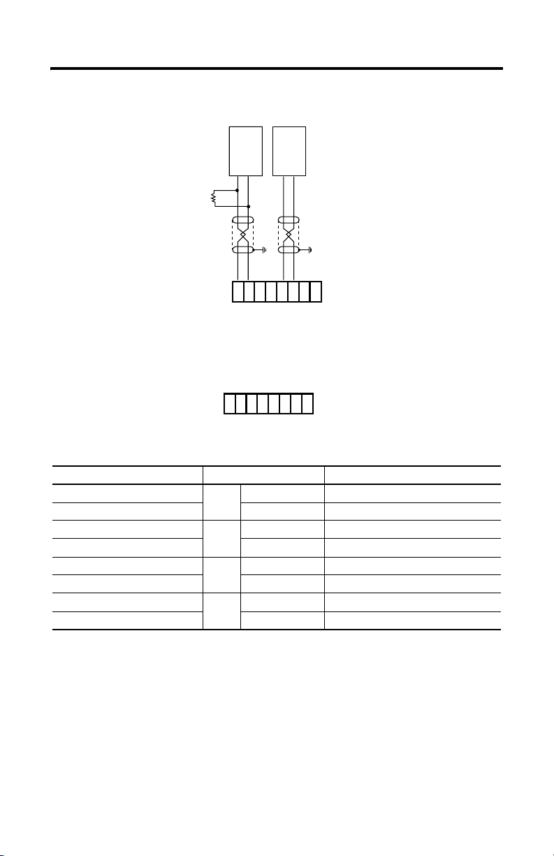
Analog cabling should be no more than 300 m (984 ft) in length and must be
shielded, twisted-pair cables for each measurement input. The shields must be
connected at one end.
IMPORTANT
Short-circuit unused input channels to the reference pole by
connecting wire jumpers.
AI
T1 I1 L- T2 I2 L-
123456
wire jumpers
wire jumpers
Analog Input Values
The following input values are available:
Input Channels Polarity Current or Voltage Range Safety Accuracy
0…+10V 0…2000
8unipolar
(1) with external 250 Ω shunt
(2) with external 500 Ω shunt
0…20 mA / 4…20 mA
0…1000
0…2000
(1)
(2)
2%
Voltage Measurment
If an open-circuit fault occurs during voltage measurement, unpredictable input
signals are received on the high resistance inputs. Values resulting from this
fluctuating input voltage are not reliable. Because the module does not feature
circuit monitoring, you must terminate input channels with a 10 kΩ resistor when
measuring voltage. Consider the internal resistance of the source as well.
Current Measurement
To measure current, connect a 500 Ω external shunt in parallel to the input.
Accuracy of the shunt must be included in accuracy calculations of the input signal.
Terminating resistors are not required for current measurement with the external
shunt connected in parallel.
Publication 1753-IN013A-EN-P - September 2005
Page 10
10 GuardPLC 1753-IF8XOF4 Analog I/O Module
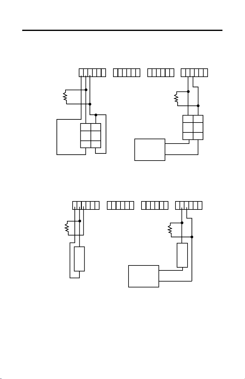
1753-IF8XOF4 with
Wiring Examples
1753-IF8XOF4 with a 4-wire device:
AI
I1T1 L-
L- T2 I2 I3T3 L-L- T4 I4 I5T5 L-L- T6 I6 I7T7 L-L- T8 I8
AI AI AI
7891011121 2 3 4 5 6 13 14 15 16 17 18 19 20 21 22 23 24
10 KΩ for Voltage
500 Ω for Current
10 KΩ for Voltage
500 Ω for Current
10 KΩ for Voltage
500 Ω for Current
++-
++-
-
-
4-wire Device with Power Source from GuardPLC 4-wire Device with External Power Source
a 2-wire device:
AI
I1T1 L-
L- T2 I2 I3T3 L-L- T4 I4 I5T5 L-L- T6 I6 I7T7 L-L- T8 I8
AI AI AI
7891011121 2 3 4 5 6 13 14 15 16 17 18 19 20 21 22 23 24
24V dc
Power
Supply
10 KΩ for Voltage
500 Ω for Current
-
+
2-wire Device with Power
Source from GuardPLC
24V dc
Power
Supply
2-wire Device with External Power Source
+
COM
-
+
+
COM
Publication 1753-IN013A-EN-P - September 2005
Page 11
GuardPLC 1753-IF8XOF4 Analog I/O Module 11
Analog Input Terminals
Analog inputs (AI) are connected to the following terminals:
Terminal Number Designation Function
1 T1 Sensor supply 1
2 I1 Analog input 1
3 L- Reference pole input 1
4 T2 Sensor supply 2
5 I2 Analog input 2
6 L- Reference pole input 2
7 T3 Sensor supply 3
8 I3 Analog input 3
9 L- Reference pole input 3
10 T4 Sensor supply 4
11 I4 Analog input 4
12 L- Reference pole input 4
13 T5 Sensor supply 5
14 I5 Analog input 5
15 L- Reference pole input 5
16 T6 Sensor supply 6
17 I6 Analog input 6
18 L- Reference pole input 6
19 T7 Sensor supply 7
20 I7 Analog input 7
21 L- Reference pole input 7
22 T8 Sensor supply 8
23 I8 Analog input 8
24 L- Reference pole input 8
Connect the Wires
See the wire size and terminal block torque specifications on page 16. The cables
are connected to the front plate of the module using pluggable terminals. Shielded
cabling is fed in from below so that the shielding can be connected to the shield
contact plate using a clip. Remove about 2 cm (3/4 in) of the outer cable insulation
so that the mesh is exposed at the point where the cable is clipped to the plate.
Publication 1753-IN013A-EN-P - September 2005
Page 12

12 GuardPLC 1753-IF8XOF4 Analog I/O Module
51 5241 42 43 44 45
Position the clip over the uninsulated cable shielding and push it into the slots of
the shield contact plate until it fits firmly in place, as shown below.
mesh
shielded cable
IMPORTANT
Make sure that the mesh comes in direct contact with the shield
contact plate. If the mesh does not touch the plate, the cable is
cable clip
not grounded.
Standard Analog Outputs
The module has 4 analog outputs, which are not safety-rated outputs. However, in
the event of an internal error, they can be shut down safely through configuration
via the user program.
ATTENTION
The following output values are available:
Value Range in the Application Output Current
00 mA
2000 20 mA
To achieve SIL 3, the output values must be read back via safety
analog inputs and evaluated in the RSLogix Guard PLUS! user
program. Otherwise, they may not be used as safety outputs.
Publication 1753-IN013A-EN-P - September 2005
Page 13
Wiring Example
GuardPLC 1753-IF8XOF4 Analog I/O Module 13
output
voltage
+- +-
current
output
500 Ω
Ground cable shields
at the shield plate.
AO
O1 O2 O3 O4
-+-+-+ - +
25 26 27 28 29 30 31 32
Analog Output Terminals
AO
01 02 03 04
-+-+-+ - +
25 26 27 28 29 30 31 32
Analog outputs (AO) are connected to the following terminals:
Terminal Number Designation Function
25
26 - Reference pole output 1
27
28 - Reference pole output 2
29
30 - Reference pole output 3
31
32 - Reference pole output 4
+ Analog output 1
O1
+ Analog output 2
O2
+ Analog output 3
O3
+ Analog output 4
O4
See the wire size and terminal block torque specifications on page 16.
Publication 1753-IN013A-EN-P - September 2005
Page 14

14 GuardPLC 1753-IF8XOF4 Analog I/O Module
Reset Pushbutton
You can use the reset button if you forget the password for connecting the
programming software. The pushbutton is accessible through a small round hole at
the top of the housing, approximately 4 to 5 cm (1.6 to 2.0 in.) from the left rim and
recessed approximately 9.5 mm (0.375 in.).
IMPORTANT
To reset, press and hold the pushbutton for 20 seconds while rebooting the device
by cycling power. Pressing the Reset pushbutton during operation has no affect.
With activation of the reset button:
• All accounts are deleted except for the default account.
• IP address and system ID (SRS) are set to default values.
At the next power cycle, these settings will be restored to the last values stored into
Flash. This means that either:
• the settings prior to the reset will be restored, or
• if any settings were changed after the reset, these new settings will still be in
effect.
Activate the reset pushbutton using an insulated pin to prevent
short-circuits.
Publication 1753-IN013A-EN-P - September 2005
Page 15
GuardPLC 1753-IF8XOF4 Analog I/O Module 15
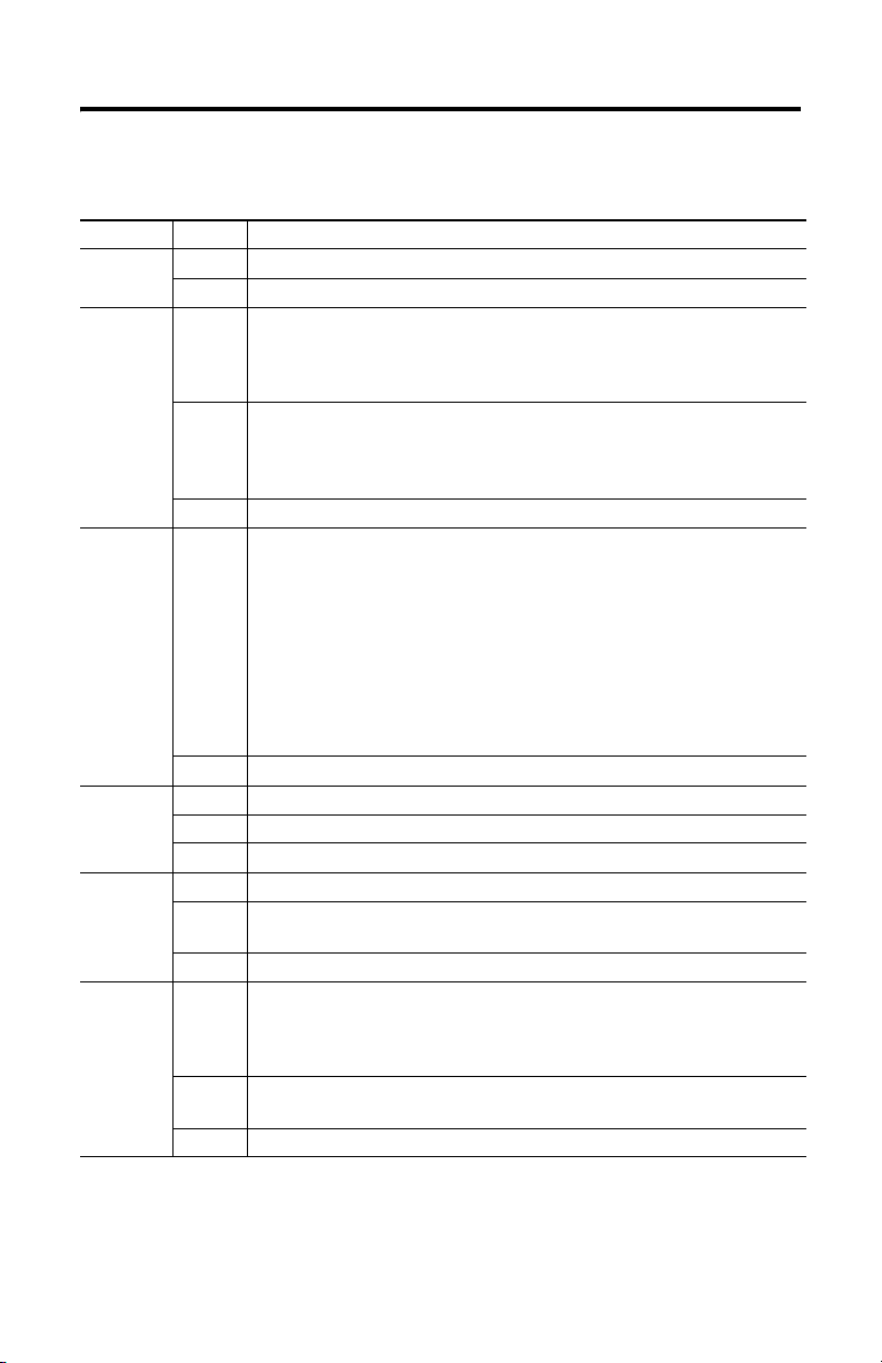
Troubleshoot with LED Indicators
Indicator State Condition
24V dc On 24V dc operating voltage present.
Off No operating voltage.
RUN On This is the normal status of the module.
A routine, which has been loaded into the controller, is executed.
The controller processes input and output signals, carries out communication, and
performs hardware and software tests.
Flashing The controller is in STOP mode and is not executing a routine.
Off The controller is in ERROR_STOP (see ERROR).
ERROR On • A hardware error has been detected by the controller. The controller goes
Off No errors are detected.
PROGress On The upload of a new controller configuration is in progress.
Flashing The upload of a new operating system into the Flash ROM is in progress.
Off No upload of controller configuration or operating system in progress.
FORCE On The controller is executing a routine (RUN) and FORCE mode is activated by the user.
Flashing The controller is in STOP, but Forcing has been initiated and will be activated when
Off Forcing is OFF.
FAULT On • The routine (logic) has caused an error.
Flashing An error has occurred during a Flash ROM write cycle.
Off None of the above errors has occurred.
All system outputs are reset.
STOP mode can be triggered by setting the Emergency stop system variable to TRUE
in the routine, or by direct command from the programming software.
to ERROR_STOP and the execution of the routine is halted. Hardware
errors are errors in the controller, errors in one or more of the digital input
and output modules, or errors in the counters.
• A software error in the operating system has been detected by the
controller.
• The watchdog has reported an error due to exceeded cycle time.
All system outputs will be reset and the controller ceases all hardware and software
tests. The controller can only be restarted by a command from the programming
software.
the controller is started.
• The controller configuration is faulty.
• The upload of a new operating system was not successful and the
operating system is corrupted.
One or more I/O errors have occurred.
Publication 1753-IN013A-EN-P - September 2005
Page 16

16 GuardPLC 1753-IF8XOF4 Analog I/O Module
Indicator State Condition
OSL Flashing Emergency Operating System Loader is active.
BL Flashing Boot Loader unable to load operating system or unable to start COMM operating
Controller status can be interrogated through the programming software. For more information, refer to the
GuardPLC™ Controller Systems User Manual (1753-UM001).
system loader.
Specifications
General
Interfaces: GuardPLC Ethernet 2 x RJ-45, 10/100BaseT (with 100 Mbps) with integrated switch
Operating Voltage 24V dc, -15% to +20%, w
separation, conforming to IEC 61131-2 requirements, as well as either
of the following:
• EN 60950 - SELV (Safety Extra Low Voltage)
• EN 60204 - PELV (Protective Extra Low Voltage)
Response Time ≥ 20 ms
Battery Backup none
Current Consumption max. 0.8 A (with max. load), idle current 0.4 A @24V
Isolation Voltage No isolation between circuits
Wiring Category
Wire Size
(1)
category 2 on communications ports, signal ports, and power ports
I/O – 16 AWG (1.5 mm
wire rated at 75 °C (167 °F) or greater with 3/64 inch (1.2 mm) insulation
maximum
15% from a power supply with protective
ss
2
) to 26 AWG (0.14 mm2) solid or stranded copper
Power – 14 AWG (2.5 mm
copper wire rated at 75 °C (167 °F) or greater with 3/64 inch (1.2 mm)
insulation maximum
Terminal Block Torque 0.51 Nm (4.5 in-lb)
Publication 1753-IN013A-EN-P - September 2005
2
) to 22 AWG (0.34 mm2) solid or stranded
Page 17

GuardPLC 1753-IF8XOF4 Analog I/O Module 17
Analog Inputs
Number of Inputs 8 (not electrically isolated)
Input Signal Range, Nominal Voltage: 0 to +10V dc
Current: 0 to +20 mA
Input Signal Range, Service Voltage: -0.1 to +11V dc
Current: -0.4 to +23 mA
Shunt Resistor, External 500 Ω (for current input)
Impedance, Analog Input >2 MΩ
Analog Input Signal, Source
≤ 500 Ω
Impedance
Input Resolution 12 bits
Effective Resolution 9 bits @ 10V
Sensor Supply selectable 26V/8.2V
200 mA, short-circuit-proof
Accuracy 0.5%
Safety Accuracy 2%
Calibration Error Zero Point ±1%
Calibration Error Terminal Point ±0.4%
Channel Error ±0.5%
Temperature Error Zero Point ±0.5%/10 K
Temperature Error Terminal Point ±0.5%/10 K
Linearity Error ±0.5%
Long-term Drift ±0.5%
Analog Outputs
Number of Outputs 4 (not electrically isolated)
non-safety with common safety switch off
Output Signal Range 4…20 mA nominal
0…20 mA full range
Resolution of Software 12 bits
Impedance, Current Output 600 Ω max.
Calibration Error Zero Point ±1%
Calibration Error Terminal Point ±1%
Channel Error ±1%
Temperature Error Zero Point ±1%/10 K
Temperature Error Terminal Point ±1%/10 K
Linearity Error ±1%
(3)
(3)
Publication 1753-IN013A-EN-P - September 2005
Page 18

18 GuardPLC 1753-IF8XOF4 Analog I/O Module
Environmental Conditions
Storage Temperature IEC 60068-2-1 (Test Ab, Un-packaged Non-operating Cold),
Operating Temperature IEC 60068-2-1 (Test Ad, Operating Cold),
Vibration IEC60068-2-6 (Test Fc, Operating): 1 g @ 10…150 Hz
Shock, Operating IEC60068-2-27 (Test Ea, Unpackaged Shock):15 g
Relative Humidity IEC 60068-2-30 (Test Db, Un-packaged Non-operating Damp Heat):
Emissions Group 1, Class A
ESD Immunity IEC 61000-4-2:
Radiated RF Immunity IEC 61000-4-3:
EFT/B Immunity IEC 61000-4-4:
Surge Transient Immunity IEC 61000-4-5:
Conducted RF Immunity IEC 61000-4-6:
Enclosure Type Rating meets IP20
Mechanical Dimensions
Width 207 mm (8.16 in.) including housing screws
Height 114 mm (4.49 in.) including latch
Depth 97 mm (3.82 in.) including grounding bolt
Weight 0.95 kg (2.09 lb)
IEC 60068-2-2 (Test Bb, Un-packaged Non-operating Dry Heat),
IEC 60068-2-14 (Test Na, Un-packaged Non-operating Thermal Shock):
-40°C to +85°C (-40°F to +185°F) without backup battery
IEC 60068-2-2 (Test Bd, Operating Dry Heat),
IEC 60068-2-14 (Test Nb, Operating Thermal Shock):
0°C to +60°C (+32°F to +140°F)
10 to 95% non-condensing
6 kV contact discharges
8 kV air discharges
10V/m with 1kHz sine-wave 80% AM from 80 Hz to 2000 MHz
±2 kV @ 5 kHz on power ports
±1 kV @ 5 kHz on signal ports
±1 kV @ 5 kHz on communication ports
±500V line-line (DM) and ±500 line-earth (CM) on DC power ports
±1 kV line-earth (CM) on shielded ports
±1 kV line-earth (CM) on communication ports
10V rms with 1 kHz sine-wave 80% AM from 150 kHz to 80 MHz
Publication 1753-IN013A-EN-P - September 2005
Page 19

GuardPLC 1753-IF8XOF4 Analog I/O Module 19
Certifications (when product is marked)
(2)
c-UL-us UL Listed Industrial Control Equipment, certified for US and Canada
CE European Union 89/336/EEC EMC Directive, compliant with:
• EN 61000-6-4; Industrial Emissions
• EN 61000-6-2; Industrial Immunity
C-Tick Australian Radiocommunications Act, compliant with:
AS/NZS CISPR 11; Industrial Emissions
TÜV TÜV Certified for Functional Safety
(1) Use this Conductor Category information for planning conductor routing. Refer to Publication 1770-4.1, Industrial
Automation Wiring and Grounding Guidelines.
(2) See the product certification link at www.ab.com for Declarations of Conformity, Certificates, and other certification details.
(3) with external shunt resistor
Publication 1753-IN013A-EN-P - September 2005
Page 20

GuardPLC is a trademark of Rockwell Automation, Inc.
All other trademarks are the property of their respective holders and are hereby acknowledged.
Publication 1753-IN013A-EN-P - September 2005 PN 40071-201-01(1)
Copyright © 2005 Rockwell Automation, Inc. A ll rights reserved. Printed in t he U.S.A.
 Loading...