

Page 1

DeviceNet Safety
Scanner for
GuardPLC™
Controllers
Catalog Number 1753-DNSI
User Manual
Page 2
Important User Information
Solid state equipment has operational characteristics differing from those of
electromechanical equipment. Safety Guidelines for the Application, Installation and
Maintenance of Solid State Controls (Publication SGI-1.1 available from your local
Rockwell Automation sales office or online at
http://www.ab.com/manuals/gi) describes some important differences
between solid state equipment and hard-wired electromechanical devices.
Because of this difference, and also because of the wide variety of uses for
solid state equipment, all persons responsible for applying this equipment
must satisfy themselves that each intended application of this equipment is
acceptable.
In no event will Rockwell Automation, Inc. be responsible or liable for
indirect or consequential damages resulting from the use or application of
this equipment.
The examples and diagrams in this manual are included solely for illustrative
purposes. Because of the many variables and requirements associated with
any particular installation, Rockwell Automation, Inc. cannot assume
responsibility or liability for actual use based on the examples and diagrams.
No patent liability is assumed by Rockwell Automation, Inc. with respect to
use of information, circuits, equipment, or software described in this manual.
Reproduction of the contents of this manual, in whole or in part, without
written permission of Rockwell Automation, Inc. is prohibited.
Throughout this manual, when necessary we use notes to make you aware of
safety considerations.
WARNING
IMPORTANT
ATTENTION
SHOCK HAZARD
BURN HAZARD
Identifies information about practices or circumstances
that can cause an explosion in a hazardous environment,
which may lead to personal injury or death, property
damage, or economic loss.
Identifies information that is critical for successful
application and understanding of the product.
Identifies information about practices or circumstances
that can lead to personal injury or death, property
damage, or economic loss. Attentions help you:
• identify a hazard
• avoid a hazard
• recognize the consequence
Labels may be located on or inside the equipment (e.g.,
drive or motor) to alert people that dangerous voltage may
be present.
Labels may be located on or inside the equipment (e.g.,
drive or motor) to alert people that surfaces may be at
dangerous temperatures.
Page 3

Before You Begin
Table of Contents
Preface
Who Should Use this Manual. . . . . . . . . . . . . . . . . . . . . . . P-1
Purpose of This Manual. . . . . . . . . . . . . . . . . . . . . . . . . . . P-1
Related Documentation . . . . . . . . . . . . . . . . . . . . . . . . . . . P-2
Common Techniques Used in This Manual. . . . . . . . . . . . . P-2
Understanding Terminology . . . . . . . . . . . . . . . . . . . . . . . P-3
Chapter 1
Safety Concept . . . . . . . . . . . . . . . . . . . . . . . . . . . . . . . . . 1-1
DeviceNet Safety Scanner Communications . . . . . . . . . . . . 1-2
How the 1753-DNSI Communicates . . . . . . . . . . . . . . . 1-2
Understand Data Signals. . . . . . . . . . . . . . . . . . . . . . . . 1-3
How Data Tables Work . . . . . . . . . . . . . . . . . . . . . . . . 1-4
How to Distinguish Between Standard Data and Safety Data
in RSLogix Guard PLUS! . . . . . . . . . . . . . . . . . . . . . . . . 1-4
Role of RSNetWorx for DeviceNet and RSLogix Guard PLUS! 1-5
DeviceNet Safety Scanner Features. . . . . . . . . . . . . . . . . . . 1-6
Hardware Overview. . . . . . . . . . . . . . . . . . . . . . . . . . . 1-6
Supported Connections . . . . . . . . . . . . . . . . . . . . . . . . 1-7
Physical Layout of the DeviceNet Safety System . . . . . . . . . 1-8
DeviceNet Safety I/O Performance Factors . . . . . . . . . . 1-8
Choose a Communication Rate for the Network . . . . . . 1-9
Assign an Address to Each Device . . . . . . . . . . . . . . . . 1-10
Install the 1753-DNSI
Set Up Your DeviceNet Network
Chapter 2
General Safety Information . . . . . . . . . . . . . . . . . . . . . . . . 2-1
Preventing Electrostatic Discharge . . . . . . . . . . . . . . . . 2-2
Mount the Scanner . . . . . . . . . . . . . . . . . . . . . . . . . . . . . . 2-2
DIN Rail Mounting. . . . . . . . . . . . . . . . . . . . . . . . . . . . 2-3
Panel Mounting . . . . . . . . . . . . . . . . . . . . . . . . . . . . . . 2-4
Ground the Scanner . . . . . . . . . . . . . . . . . . . . . . . . . . . . . 2-4
Connect Power Source . . . . . . . . . . . . . . . . . . . . . . . . . . . 2-5
Make Communication Connections . . . . . . . . . . . . . . . . . . 2-5
DeviceNet Connections . . . . . . . . . . . . . . . . . . . . . . . . 2-6
High-speed Safety Protocol (HSP) Connections . . . . . . . 2-7
Chapter 3
Connect a Computer to the DeviceNet Network . . . . . . . . . 3-1
Configure a Driver for the Network . . . . . . . . . . . . . . . 3-1
Make Sure the Driver Works. . . . . . . . . . . . . . . . . . . . . 3-2
Commission All Nodes . . . . . . . . . . . . . . . . . . . . . . . . . . . 3-2
Browse the Network . . . . . . . . . . . . . . . . . . . . . . . . . . . . . 3-3
Safety Reset (Optional) . . . . . . . . . . . . . . . . . . . . . . . . . . . 3-4
Set Passwords (Optional). . . . . . . . . . . . . . . . . . . . . . . . . . 3-5
Set or Change a Password . . . . . . . . . . . . . . . . . . . . . . 3-5
1 Publication 1753-UM002A-EN-P - July 2005
Page 4

Table of Contents 2
Manage the Safety Network
Number
Configure DeviceNet Nodes and
Connections
To set a password for a module: . . . . . . . . . . . . . . . . . 3-5
Forgotten Passwords . . . . . . . . . . . . . . . . . . . . . . . . . . 3-6
Chapter 4
SNN Formats. . . . . . . . . . . . . . . . . . . . . . . . . . . . . . . . . . . 4-1
Time-based SNN (Recommended) . . . . . . . . . . . . . . . . 4-1
Manual SNN . . . . . . . . . . . . . . . . . . . . . . . . . . . . . . . . 4-2
Assignment of the SNN . . . . . . . . . . . . . . . . . . . . . . . . . . . 4-2
Automatic (Time-based) . . . . . . . . . . . . . . . . . . . . . . . . 4-2
Manual . . . . . . . . . . . . . . . . . . . . . . . . . . . . . . . . . . . . 4-3
Set the SNN in All Safety Nodes. . . . . . . . . . . . . . . . . . . . . 4-3
SNN Mismatch . . . . . . . . . . . . . . . . . . . . . . . . . . . . . . . . . 4-5
Safety Network Number Mismatch Dialog . . . . . . . . . . . 4-5
SNN and Node Address Changes . . . . . . . . . . . . . . . . . . . . 4-6
Chapter 5
Configuration Signature. . . . . . . . . . . . . . . . . . . . . . . . . . . 5-1
Configure DeviceNet Safety I/O Target Nodes . . . . . . . . . . 5-2
1791DS DeviceNet Safety I/O Module Parameters . . . . . 5-2
Configure the DeviceNet Safety Scanner’s Safety
Connections . . . . . . . . . . . . . . . . . . . . . . . . . . . . . . . . . . . 5-3
Configure DeviceNet Standard Slave I/O Nodes . . . . . . . . . 5-6
Configure the DeviceNet Safety Scanner’s Standard
Connections . . . . . . . . . . . . . . . . . . . . . . . . . . . . . . . . . . . 5-6
Standard Communication Properties . . . . . . . . . . . . . . . 5-6
Create a Scanlist. . . . . . . . . . . . . . . . . . . . . . . . . . . . . . 5-8
Configure Standard Inputs . . . . . . . . . . . . . . . . . . . . . . 5-10
Configure Standard Outputs . . . . . . . . . . . . . . . . . . . . . 5-11
Configure GuardPLC Controller Settings . . . . . . . . . . . . . . . 5-12
Create a GuardPLC Project with
High-Speed Safety Protocol
Associate the Scanner and
Controller and Download the
DeviceNet Network Configuration
Publication 1753-UM002A-EN-P - July 2005
Chapter 6
Create or Open a GuardPLC Project . . . . . . . . . . . . . . . . . 6-1
Add High-Speed Safety Protocol to the GuardPLC Controller
Resource. . . . . . . . . . . . . . . . . . . . . . . . . . . . . . . . . . . . . . 6-3
Review the GuardPLC Controller’s Communication Settings 6-5
Chapter 7
Scanner Signals File. . . . . . . . . . . . . . . . . . . . . . . . . . . . . . 7-1
Target Connections File. . . . . . . . . . . . . . . . . . . . . . . . . . . 7-2
Automatically Update Signals. . . . . . . . . . . . . . . . . . . . . . . 7-2
Manually Associate the Scanner and Controller. . . . . . . . . . 7-4
Download the DeviceNet Network Configuration . . . . . . . . 7-5
Page 5

Develop Your GuardPLC
Application
Verify Your DeviceNet Safety
Configuration
Table of Contents 3
Chapter 8
Define Signals for Your GuardPLC Application . . . . . . . . . . 8-1
Define Signals for Safety Data. . . . . . . . . . . . . . . . . . . . 8-1
Configure HSP Connection. . . . . . . . . . . . . . . . . . . . . . 8-3
Create Application Program Logic . . . . . . . . . . . . . . . . . . . 8-4
Save and Compile Application Logic . . . . . . . . . . . . . . . . . 8-4
Download the Project to the Controller . . . . . . . . . . . . . . . 8-4
Place the Controller in Stop Mode (if necessary) . . . . . . 8-4
Download the Project . . . . . . . . . . . . . . . . . . . . . . . . . 8-4
Chapter 9
Start the Safety Device Verification Wizard . . . . . . . . . . . . . 9-1
Determine if Devices Can Be Verified . . . . . . . . . . . . . . . . 9-1
Select Devices to Verify. . . . . . . . . . . . . . . . . . . . . . . . . . . 9-3
Review the Safety Device Verification Reports . . . . . . . . . . 9-5
Lock Safety Devices . . . . . . . . . . . . . . . . . . . . . . . . . . . . . 9-6
View the Safety Device Verification Wizard Summary . . . . . 9-7
Monitor Status
Specifications
Configure Peer-to-Peer DeviceNet
Communications
Chapter 10
LED Status Indicators. . . . . . . . . . . . . . . . . . . . . . . . . . . . . 10-1
Alphanumeric Display . . . . . . . . . . . . . . . . . . . . . . . . . . . . 10-2
At Power Up . . . . . . . . . . . . . . . . . . . . . . . . . . . . . . . . 10-2
During Operation . . . . . . . . . . . . . . . . . . . . . . . . . . . . 10-2
Connection Status . . . . . . . . . . . . . . . . . . . . . . . . . . . . . . . 10-9
DeviceNet Connection Status Bit Behavior . . . . . . . . . . 10-9
DeviceNet Safety Connection Status . . . . . . . . . . . . . . 10-10
Standard DeviceNet Connection Status . . . . . . . . . . . . 10-11
DeviceNet Interface Status . . . . . . . . . . . . . . . . . . . . . 10-12
Appendix A
General . . . . . . . . . . . . . . . . . . . . . . . . . . . . . . . . . . . . . . A-1
Environmental . . . . . . . . . . . . . . . . . . . . . . . . . . . . . . . . . A-1
Electrical/EMC . . . . . . . . . . . . . . . . . . . . . . . . . . . . . . . . . A-2
Certifications. . . . . . . . . . . . . . . . . . . . . . . . . . . . . . . . . . . A-3
Appendix B
Plan Your Peer-to-Peer Communications . . . . . . . . . . . . . . B-2
Commission a Peer Scanner. . . . . . . . . . . . . . . . . . . . . . . . B-2
Add a Peer Controller . . . . . . . . . . . . . . . . . . . . . . . . . . . . B-3
Define Target Connections for Standard and Safety Data. . . B-4
Create Required Signals . . . . . . . . . . . . . . . . . . . . . . . . B-5
Define Standard Target Connections . . . . . . . . . . . . . . . B-6
Define Safety Connections . . . . . . . . . . . . . . . . . . . . . . B-7
Configure Peer-to-Peer Connections. . . . . . . . . . . . . . . . . . B-8
Publication 1753-UM002A-EN-P - July 2005
Page 6

Table of Contents 4
DeviceNet Class Codes
Calculate Safety Connection
Bandwidth
Associate the Peer Safety Scanner and GuardPLC
Controller . . . . . . . . . . . . . . . . . . . . . . . . . . . . . . . . . . B-8
Add the Peer Scanner to the Scanlist. . . . . . . . . . . . . . . B-9
Configure Safety Connections. . . . . . . . . . . . . . . . . . . B-10
Appendix C
DeviceNet Object . . . . . . . . . . . . . . . . . . . . . . . . . . . . . . . C-1
Identity Object . . . . . . . . . . . . . . . . . . . . . . . . . . . . . . . . . C-1
Safety Supervisor Object . . . . . . . . . . . . . . . . . . . . . . . . . . C-1
Appendix D
Single-cast Inputs . . . . . . . . . . . . . . . . . . . . . . . . . . . . . . . D-1
1 to 2 Bytes . . . . . . . . . . . . . . . . . . . . . . . . . . . . . . . . . D-1
3 to 250 Bytes . . . . . . . . . . . . . . . . . . . . . . . . . . . . . . . D-1
Single-cast Outputs . . . . . . . . . . . . . . . . . . . . . . . . . . . . . . D-2
1 to 2 Bytes . . . . . . . . . . . . . . . . . . . . . . . . . . . . . . . . . D-2
3 to 250 Bytes . . . . . . . . . . . . . . . . . . . . . . . . . . . . . . . D-2
Multicast Connections . . . . . . . . . . . . . . . . . . . . . . . . . . . . D-2
1 to 2 Bytes . . . . . . . . . . . . . . . . . . . . . . . . . . . . . . . . . D-2
3 to 250 Bytes . . . . . . . . . . . . . . . . . . . . . . . . . . . . . . . D-3
Glossary
Index
Publication 1753-UM002A-EN-P - July 2005
Page 7

Preface
Read this preface to familiarize yourself with the rest of the manual. It
provides information concerning:
• who should use this manual
• the purpose of this manual
• related documentation
• common techniques used in this manual
• terminology used in this manual
Who Should Use this Manual
Purpose of This Manual
Use this manual if you are responsible for designing, installing,
programming, or troubleshooting a safety control system that includes
a GuardPLC controller communicating on a DeviceNet Safety network
through a 1753-DNSI module.
We assume that you:
• have a basic understanding of electrical circuitry
• are trained and experienced in the creation, operation, and
maintenance of safety systems.
• know each of your device’s I/O parameters and requirements.
This manual only briefly describes the safety concept of the DeviceNet
Safety Scanner for GuardPLC Controllers. Its purpose is to provide
information on installing, operating, and maintaining your 1753-DNSI
in a GuardPLC controller system.
For detailed information on safety system requirements regarding the
DeviceNet Safety Scanner for GuardPLC Controllers, refer to the
GuardPLC Controller Systems Safety Reference Manual, publication
number 1753-RM002.
1 Publication 1753-UM002A-EN-P - July 2005
Page 8
2 Preface
Related Documentation
The table below provides a listing of publications that contain
important information about GuardPLC Controller systems.
For Read this document Publication
Information on installing, programming, operating, and
troubleshooting a GuardPLC Controller
Detailed requirements for achieving and maintaining SIL 3
applications with the GuardPLC Controller System
Information on installing the DeviceNet Safety Scanner for
GuardPLC Controllers
Information on installing DeviceNet Safety I/O Modules DeviceNet Safety I/O Installation Instructions 1791DS-IN001
Information on configuration and programming for DeviceNet
Safety I/O Modules
GuardPLC Controller User Manual 1753-UM001
GuardPLC Controller Systems Safety Reference Manual 1753-RM002
DeviceNet Safety Scanner for GuardPLC Installation
Instructions
DeviceNet Safety I/O User Manual 1791DS-UM001
1753-IN009
If you would like a manual, you can:
• download a free electronic version from the internet at
www.rockwellautomation.com/literature.
• purchase a printed manual by contacting your local
Allen-Bradley distributor or Rockwell Automation sales office.
Common Techniques Used in This Manual
The following conventions are used throughout this manual:
• Bulleted lists, such as this one, provide information, not
procedural steps.
• Numbered lists provide sequential steps or hierarchical
information.
Publication 1753-UM002A-EN-P - July 2005
Page 9

Preface 3
Understanding Terminology
Acronym: Full Term: Definition:
1oo2 One Out of Two A safety architecture consisting of two channels connected in parallel, such
CAN Controller Area Network The networking standard that defines the physical layer of DeviceNet.
COS Change of State A type of I/O data communication in which the interface module can send and
EDS Electronic Data Sheet A vendor-supplied template that specifies how device configuration
EPR Expected Packet Rate The rate at which packets are expected to be received by a device.
HSP High-Speed Safety Protocol A high-speed, high-integrity protocol designed to transfer both safety and
MAC ID Media Access Identifier The network address of a DeviceNet node.
MTBF Mean Time Between Failures Average time between failure occurrences.
MTTR Mean Time to Restoration Average time needed to restore normal operation after a failure has occurred.
PC Personal Computer Computer used to interface with, and control, a controller-based system via
The following table defines acronyms used in this manual.
that either channel can perform the safety function.
receive data with slave devices whenever a data change occurs in the
configured slave device.
information is displayed as well as what is an appropriate entry (value).
standard data between the GuardPLC controller and the DeviceNet Safety
Scanner for GuardPLC Controllers.
programming software.
PFD Probability of Failure on Demand The average probability of a system to fail to perform its design function on
demand.
PFH Probability of Failure per Hour The probability of a system to have a dangerous failure occur per hour.
Rx Receive —
SNN Safety Network Number A unique number that identifies a safety network, or safety sub-net, across all
networks in the safety system.
Tx Transmit —
Publication 1753-UM002A-EN-P - July 2005
Page 10

4 Preface
Publication 1753-UM002A-EN-P - July 2005
Page 11

Chapter
Before You Begin
This chapter provides an overview of communication between the
1753-DNSI and the GuardPLC controller. Before configuring your
1753-DNSI module, you must understand:
• the safety concept of the system
• the data exchange between the GuardPLC controller and
DeviceNet devices through the 1753-DNSI module
• the roles of RSNetWorx for DeviceNet and RSLogix Guard PLUS!
software in the safety system
• the features of the DeviceNet Safety Scanner
• the physical layout of your network
1
Safety Concept
The DeviceNet Safety Scanner for GuardPLC Controllers is certified for
use in GuardPLC safety applications up to and including Safety
Integrity Level (SIL) 3, according to IEC 61508, and Category (CAT) 4,
according to EN 954-1, in which the de-energized state is the safety
state.
IMPORTANT
The DeviceNet Safety Scanner and the GuardPLC system use the
following mechanisms to support the integrity of the data they
exchange:
• Safety Network Number – A unique number that identifies the
Safety Network. Each DeviceNet sub-network that contains
safety nodes must have one unique Safety Network Number.
• Configuration Signature – The combination of an ID number,
date, and time that uniquely identifies a specific configuration
for a safety device.
For SIL 3 and CAT 4 safety system requirements,
including proof test intervals, system reaction time,
and PFD/PFH calculations, refer to the GuardPLC
Controller Systems Safety Reference Manual,
publication number 1753-RM002. You must read,
understand, and fulfill these requirements prior to
operating a GuardPLC controller-based SIL 3 or CAT
4 safety system.
1 Publication 1753-UM002A-EN-P - July 2005
Page 12

1-2 Before You Begin
• HSP (High-speed Safety Protocol) Signature – This is a
read-only value that represents the data exchanged between the
GuardPLC controller and the safety scanner. The HSP Signature
is calculated based on the Scanner Configuration Signature and
changes only when the data exchanged by the controller and
the safety scanner changes. The HSP Signature is sent to the
controller configuration software and helps ensure the integrity
of the data.
• Controller ID (SRS) – A unique identifier for every GuardPLC
controller and GuardPLC Ethernet Distributed I/O module in a
system, the Controller ID must be a unique number from 1 to
65,535. The default is 60000.
• Safety-Lock – The safety scanner and DeviceNet safety I/O
modules must be Safety-Locked to prevent their configurations
from being unintentionally modified. Safety-Lock all DeviceNet
Safety devices by running the Safety Device Verification Wizard
in RSNetWorx for DeviceNet before placing the safety
application into service.
• Password protection – The configuration of the safety scanner
can be protected by the use of an optional password. If you set
a password in a safety device, the download, Safety-Reset,
Safety-Lock and Safety-Unlock operations will require a
password.
DeviceNet Safety Scanner Communications
The 1753-DNSI provides DeviceNet access for GuardPLC 1600 and
GuardPLC 1800 controllers. These GuardPLC controllers support
communications via High-Speed Safety Protocol (HSP). The
1753-DNSI reads and writes data from DeviceNet nodes and
exchanges this aggregate data with the GuardPLC controller via HSP.
The 1753-DNSI scanner communicates with DeviceNet devices over
the network to:
• read inputs from a device
• write outputs to a device
• monitor device status
How the 1753-DNSI Communicates
For standard data, the safety scanner communicates with a device
via strobe, poll, change of state, and/or cyclic messages. It uses these
messages to solicit data from or deliver data to each device in its
scanlist.
Publication 1753-UM002A-EN-P - July 2005
Page 13
Before You Begin 1-3
For safety data, the scanner communicates with safety devices via
cyclic messages only. You configure input and output connections in
the DeviceNet safety scanner to transfer input and output data to and
from DeviceNet safety I/O modules and the GuardPLC controller.
The scanner can make data available to other DeviceNet scanners
using Target connections. When Target connections are enabled, the
safety scanner looks like a standard I/O device that can be added to
another scanner’s scanlist,or a safety target device allowing another
safety scanner to connect to the safety data by adding a safety
connection. This allows for the transfer of data signals between two
GuardPLC controllers for safety interlocking and distributed safety
control. Standard data signals can also be exchanged with PLCs, HMIs,
or a ControlLogix system with a 1756-DNB scanner on the DeviceNet
network. For more information on Target connections, see
Appendix B.
Understand Data Signals
In order to understand how to use data signals from the safety scanner
in your GuardPLC application logic, you must know:
• whether the signal data is regarded as safety or standard data in
the end device, and
• whether the signal data was transferred over a safety connection
or a standard connection.
The following table defines permitted uses of safety and standard
signals based on connection and signal type.
End Device Signal
Definition
Safety Safety Safety
Standard Safety Standard
Connection Type Permitted Use in Application
Standard Standard
Standard Standard
IMPORTANT
Only safety signal data transmitted over safety
connections may be used as safety data in safety
application logic.
Publication 1753-UM002A-EN-P - July 2005
Page 14
1-4 Before You Begin
How Data Tables Work
To exchange data, the GuardPLC controller and the 1753-DNSI use
two pairs of data tables: one pair for safety input and output data and
one pair for standard input and output data.
Connection Type Scanner Inputs Scanner Outputs
Scanner is the
originator.
Data the scanner reads from
its target nodes. The data
layout is defined by the
target node’s configuration.
Data the scanner writes to
its target nodes. The data
layout is defined by the
target node’s configuration.
Safety
Standard
Scanner is the
target.
Scanner is the
master.
Scanner is the
slave.
Data that one other CIP
Safety originator may write
on the scanner’s target
output connection point. The
data signals to be written
are selected in RSLogix
Guard PLUS!.
Data the scanner reads from
its standard DeviceNet
slaves. The data layout is
defined by the target node’s
configuration.
Data that one other
standard DeviceNet master
can write on the scanner’s
slave mode outputs. The
data signals are selected in
RSLogix Guard PLUS!.
Data that one or more other
CIP Safety originators may
read from the scanner’s
target input connection
point. The data signals to be
read are selected in RSLogix
Guard PLUS!.
Data the scanner writes to
its standard DeviceNet
slaves. The data layout is
defined by the target node’s
configuration.
Data that one or more other
standard DeviceNet master
can read from the scanner’s
slave mode inputs. The data
signals are selected in
RSLogix Guard PLUS!.
Standard DeviceNet Explicit Messaging connections are limited to
read-only access to safety data.
ATTENTION
To maintain the safety integrity level (SIL) of your
system, you must ensure that safety data read by
Explicit Messaging is used only as standard data in
your application.
Publication 1753-UM002A-EN-P - July 2005
How to Distinguish Between Standard Data and Safety Data in
RSLogix Guard PLUS!
In the HSP Signal Connection dialogs (in RSLogix Guard PLUS!),
signals that are transferred over safety connections are shown in white
text on a red background. Signals transferred over a standard
connection are shown in blue text on a gray background.
Page 15
Before You Begin 1-5
Since this colorization only applies to the Connect Signals dialogs
available from the HSP protocol context menu, we strongly
recommend that when using both standard and safety signals in your
application, you use a naming convention to visually distinguish
between standard and safety signals throughout the RSLogix Guard
PLUS! programming environment. For example, use a prefix of ‘std_’
for any signals that are standard and a prefix of ‘safe_’ for any signals
that are safety-related.
Role of RSNetWorx for DeviceNet and RSLogix Guard PLUS!
IMPORTANT
The red/blue colorization is not a guarantee that a
signal is a safety signal. It only indicates which type
of connection the signal was transferred over. The
classification of the end node must also be
considered. Any signal that appears in the (blue)
standard Connect Signals window and is regarded as
safety at the end device must be treated as standard
in your application. Any signal that appears in the
(red) safety Connect Signals window and is regarded
as standard at the end device must be treated as
standard in your application. In order for a signal to
be regarded as a safety value in your application, the
end device configuration must treat it as safety and it
must be transferred over a DeviceNet Safety
connection.
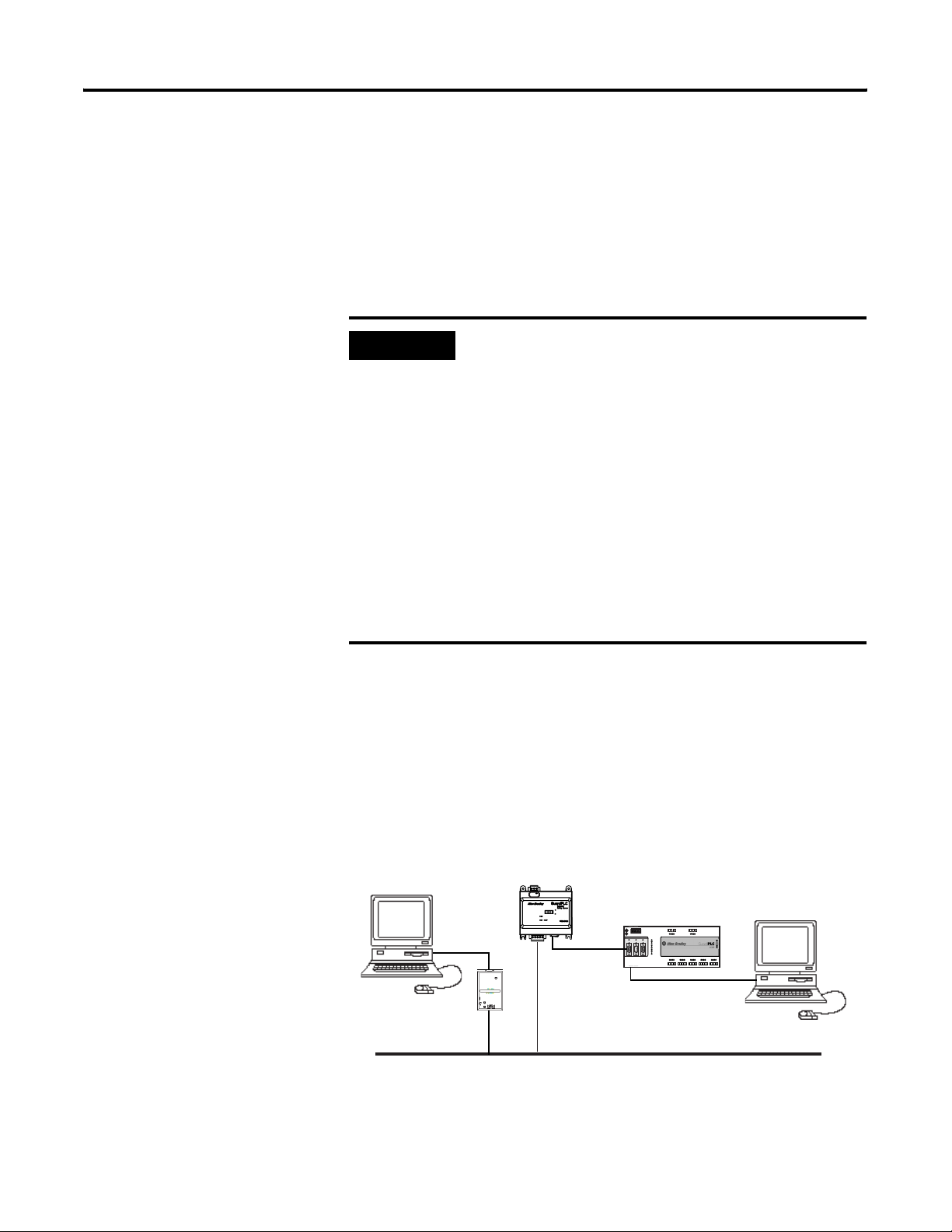
RSNetWorx for DeviceNet, version 6.x or higher, is the configuration
tool for the 1753-DNSI on the DeviceNet Safety network. RSNetWorx
for DeviceNet can connect to the safety scanner directly over the
DeviceNet network via an RS-232 interface (1770-KFD module) or PC
card (1784-PCD or -PCID) or through another network using a bridge
device. A bridge can be either a single device with communication
ports for two different networks, or separate communication devices
in the same chassis.
PC with RSNetWorx for
DeviceNet Software
1753-DNSI
L+L24V dc
GuardPLC Controller
(—)4(—)
3
L-L- L+ L+
24V DC
RS-485
PROFIBUS
ASCII/HSP
COMM1
COMM2
COMM3
GuardPLC Ethernet
10/100 BaseT
(—)4(—)
3
24 V DC
RUN
ERROR
PROG
FORCE
FAULT
OSL
BL
123456
1234
56
1L-
L-DO 2
34
(2A)
5L-D1678
1LS+- LS+ LS+ LS+ LS+L-D1234
1920 2122 23 24
1314 1516 17 18
1920 2122 23 241314 1516 23 24 2526 2728 29 30 3132 3334 35 36 37 38 3940 41 42
789101112
78910
1112
5L- L-DO 6
78
(2A)
13 L-D1141516
9L-D1101112
3132 3334 35 36
2526 2728 29 30
PC with RSLogix Guard
PLUS! Software
1753-L28BBBM
20 DC Inputs
8 DC Outputs
17 L-D1181920
3738 3940 41 42
1770-KFD PC
Communication
Module
DeviceNet
RSNetWorx for DeviceNet exchanges signal information with RSLogix
Guard PLUS!, the configuration and programming tool for the
GuardPLC controller. The Scanner Signals and Target Connections
Publication 1753-UM002A-EN-P - July 2005
Page 16
1-6 Before You Begin
Files enable RSNetWorx for DeviceNet and RSLogix Guard PLUS! to
share the same view of the individual signals available on all of the
DeviceNet connections present in a specific DeviceNet Safety Scanner
configuration.
TIP
If you install RSLogix Guard PLUS! and RSNetWorx
for DeviceNet on the same PC, you can take
advantage of the ‘Automatically Update Signals’
feature. Otherwise, you must manually import and
export the Scanner Signals and Target Connections
files. See Chapter 7, Associate the Scanner and
Controller and Download the DeviceNet Network
Configuration, for more information.
The following table lists the software and revision level required to
operate with the 1753-DNSI scanner.
Function Software Revision
Communications RSLinx 2.42 or higher
DeviceNet Configuration RSNetWorx for DeviceNet 6.x or higher
RSLogix Guard PLUS!,
Program Management
Programming Application Logic
RSLogix Guard PLUS!,
Hardware Management
4.0 or higher
6.x or higher
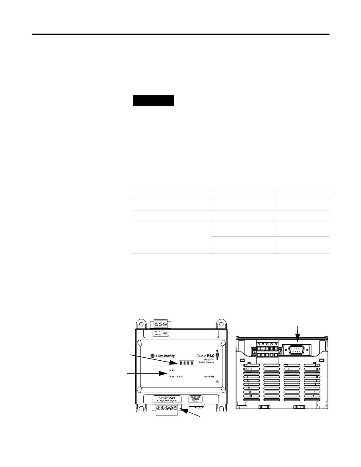
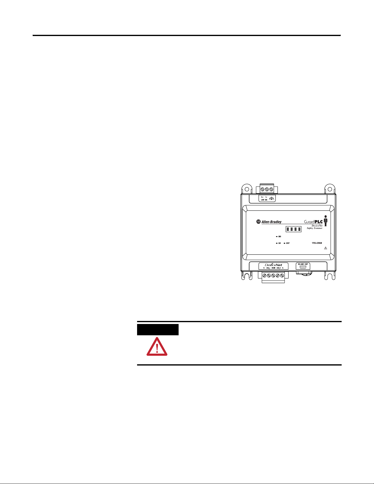
DeviceNet Safety Scanner Features
character display
LED Indicators
Publication 1753-UM002A-EN-P - July 2005
Hardware Overview
Front View Bottom View
HSP Port
DeviceNet Safety Port
Page 17

Before You Begin 1-7
The 1753-DNSI features two communication ports; one for DeviceNet
communications and one for High-Speed Safety Protocol (HSP)
communication with a GuardPLC controller. The HSP port is a 1 Mbps,
full-duplex RS-485 interface.
The safety scanner also features a 4-character dot-matrix display,
which provides status and error codes. Status LEDs on the safety
scanner indicate module, network, and HSP connection status. See
Chapter 10 for more information.
Supported Connections
The DeviceNet Safety port supports a maximum of 32 DeviceNet
Safety input connections, 32 DeviceNet Safety output connections,
and standard connections for up to 63 nodes.
The safety scanner does not support Quick Connect, Auto Device
Replacement or Autoscan.
Safety Connections
The safety scanner supports single-cast producing or consuming
connections and multi-cast consuming connections as a DeviceNet
Safety originator. Up to 32 producing and 32 consuming safety
connections can be made. These connections are used when the
safety scanner is communicating to distributed safety I/O modules.
The safety scanner also supports the use of two safety targets, defined
by RSLogix Guard PLUS! and made available via the Target
Connections File. One target may be a single- or multi-cast producer,
the other may be a single-cast consumer. These connections allow the
safety scanner to look like safety I/O to another safety scanner on the
network, and can be used for interlocking of safety data between two
GuardPLC systems.
Standard Connections
The safety scanner supports the following standard DeviceNet
connection types:
Standard Master Connections Standard Slave Connections
Polled Polled
Change of State (COS) —
Cyclic —
Bit Strobe —
Publication 1753-UM002A-EN-P - July 2005
Page 18

1-8 Before You Begin
Communication Rate
The safety scanner supports the following communication rates, but
does not support autobaud:
• 125 Kbps (default)
• 250 Kbps
• 500 Kbps
Physical Layout of the DeviceNet Safety System
Planning your system helps ensure that you can:
• meet safety times
• use memory and bandwidth efficiently
• fulfill device-specific requirements
• leave room for system expansion
Before configuring your 1753-DNSI scanner, you should be familiar
with each of the DeviceNet devices on your network. You should
know each device’s:
• system safety time requirements
• communication requirements
• I/O size
• frequency of message delivery
You must also understand and define which data elements can be
treated as safety and which as standard in your intended
configuration.
Publication 1753-UM002A-EN-P - July 2005
DeviceNet Safety I/O Performance Factors
Safety nodes have priority on a DeviceNet network, but the
performance of DeviceNet Safety I/O modules can be affected by the:
• baud rate of the network (Lower baud rates mean slower
transmissions and slower responses.)
• packet size for the various connections (Bigger packets may
result in fragmented messages and slower responses than
single-packet messages, but use fewer resources.)
• type and number of connections used (Using point-to-point
connections to make multiple connections to an input node uses
more resources than a multicast connection.)
• RPI of the devices (Lower RPIs consume more bandwidth but
lower system reaction time.)
Page 19
Before You Begin 1-9
Choose a Communication Rate for the Network
The default communication rate for a DeviceNet network is
125K bit/s. This is the easiest communication rate to use.
If you choose to use a different communication rate, the length of the
trunkline and type of cable determine which communication rates
your application can support.
Communication
Rate
125K bit/s 420 m (1378 ft) 500 m (1640 ft) 100 m (328 ft) 156 m (512 ft)
250K bit/s 200 m (656 ft) 250 m (820 ft) 100 m (328 ft) 78 m (256 ft)
500K bit/s 75 m (246 ft) 100 m (328 ft) 100 m (328 ft) 39 m (128 ft)
IMPORTANT
flat cable thick cable thin cable
If you change the communication rate of your
Maximum Distance
Cumulative Drop
Line Length
network, make sure that all devices change to the
new communication rate. Mixed communication
rates produce communication errors.
Set the baud rate of the DeviceNet Safety Scanner using the Node
Commissioning tool in RSNetWorx for DeviceNet. See Commission All
Nodes on page 3-2.
The following table lists the most common methods for setting
communication rates for other DeviceNet devices.
Method Description
autobaud At power up, the device automatically sets its communication
rate to the baud rate of the first device it finds on the network.
The device remains set until it powers up again.
The network requires at least one device with a fixed
communication rate so that the autobaud devices have something
against which to set. Typically, scanners and network interfaces
have a fixed communication rate.
switches or
pushbuttons on the
device
software Some devices require a programming device to set its address
Some devices have switches or a pushbutton that sets the
communication rate. Typically, the switch or pushbutton lets you
select either autobaud or a fixed communication rate (125K, 250K,
or 500K bit/s). The device reads the switch setting at power up. If
you change the setting, you must cycle power for the change to
take effect.
and communication rate. For example, you can use the Node
Commissioning tool in RSNetWorx for DeviceNet to set the
communication rate of a device.
Publication 1753-UM002A-EN-P - July 2005
Page 20
1-10 Before You Begin
Assign an Address to Each Device
To communicate on the DeviceNet network, each device requires its
own address. Follow the recommendations below when assigning
addresses to the devices on your network.
Give this device This address Notes
scanner 0 If you have multiple scanners, give them
the lowest addresses in sequence.
any device on your network,
except the scanner
RSNetWorx for DeviceNet
workstation
no device 63 Leave address 63 open. This is where a
1 to 61 Gaps between addresses are allowed
and have no effect on system
performance. Leaving gaps gives you
more flexibility as you develop your
system.
62 If you connect a computer directly to the
DeviceNet network, use address 62 for
the computer or bridging/linking device.
non-commissioned node typically enters
the network.
Standard DeviceNet assigns communication priority based on the
device’s node number. The lower the node number, the higher the
device’s communications priority. This priority becomes important
when multiple nodes are trying to communicate on the network at the
same time.
DeviceNet Safety nodes have additional priority on the network,
regardless of node number. DeviceNet Safety communications from
devices with lower node numbers have priority over DeviceNet Safety
communications from devices with higher node numbers.
Publication 1753-UM002A-EN-P - July 2005
Page 21
General Safety Information
Install the 1753-DNSI
Chapter
2
ATTENTION
ATTENTION
Safety Applications
Personnel responsible for the application of
safety-related Programmable Electronic System (PES)
shall be aware of the safety requirements in the
application of the system and shall be trained in
using the system.
Environment and Enclosure
This equipment is intended for use in a Pollution
Degree 2 industrial environment, in overvoltage
Category II applications (as defined in IEC
publication 60664-1), at altitudes up to 2000 meters
without derating.
This equipment is considered Group 1, Class A
industrial equipment according to IEC/CISPR
Publication 11. Without appropriate precautions,
there may be potential difficulties ensuring
electromagnetic compatibility in other environments
due to conducted as well as radiated disturbance.
This equipment is supplied as "open type"
equipment. It must be mounted within an enclosure
that is suitably designed for those specific
environmental conditions that will be present and
appropriately designed to prevent personal injury
resulting from accessibility to live parts. The interior
of the enclosure must be accessible only by the use
of a tool. Subsequent sections of this publication
may contain additional information regarding
specific enclosure type ratings that are required to
comply with certain product safety certifications.
See NEMA Standards publication 250 and IEC
publication 60529, as applicable, for explanations of
the degrees of protection provided by different
types of enclosure. Also, see the appropriate
sections in this publication, as well as the
Allen-Bradley publication 1770-4.1 (Industrial
Automation Wiring and Grounding Guidelines), for
additional installation requirements pertaining to
this equipment.
1 Publication 1753-UM002A-EN-P - July 2005
Page 22
2-2 Install the 1753-DNSI
ATTENTION
Protective Debris Strip
Do not remove the protective debris strip until after
the module and all other equipment in the panel
near the module is mounted and wiring is complete.
Once wiring is complete, remove the protective
debris strip. Failure to remove the strip before
operating can cause overheating.
Preventing Electrostatic Discharge
ATTENTION
This equipment is sensitive to electrostatic discharge,
which can cause internal damage and affect normal
operation. Follow these guidelines when you handle
this equipment:
• Touch a grounded object to discharge potential
static.
• Wear an approved grounding wrist-strap.
• Do not touch connectors or pins on component
boards.
• Do not touch circuit components inside the
equipment.
• If available, use a static-safe workstation.
• When not in use, store the equipment in
appropriate static-safe packaging.
Mount the Scanner
Publication 1753-UM002A-EN-P - July 2005
IMPORTANT
For effective cooling:
• Because of thermal considerations, mount the
module horizontally only.
• Provide a gap of at least 100 mm (3.94 in.) above,
below, and on each side of the module.
• Provide a gap of at least 51 mm (2.0 in.) from the
front face of the module to the door of the
enclosure.
• Select a location where air flows freely or use an
additional fan.
• Do not mount the module over a heating device.
Page 23
Install the 1753-DNSI 2-3
The module can be DIN rail or panel-mounted as described in the
following sections.
ATTENTION
Be careful of metal chips when drilling mounting
holes for your module or other equipment within the
enclosure or panel. Drilled fragments that fall into
your module could cause damage.
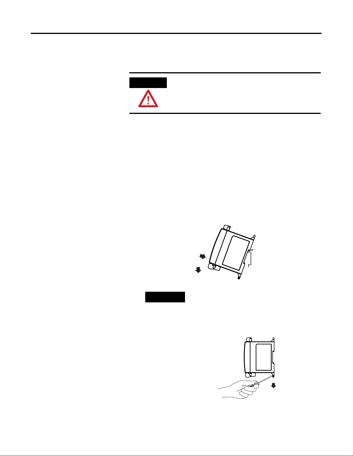
DIN Rail Mounting
Mount the module to a EN50022-35x7.5 or EN50022-35x15 DIN rail by
following the steps below:
1. Close the DIN latches, if they are open.
2. Hook the top slot over the DIN rail.
3. While pressing the module down against the top of the rail, snap
the bottom of the module into position.
TIP
To remove the module from the DIN rail,
insert a flathead screwdriver into the gap
between the housing and each latch and
pull the latch downward. When both DIN
latches are open, lift the module off of the
rail.
The maximum extension of each DIN rail latch is 14 mm (0.55 in) in
the open position.
Publication 1753-UM002A-EN-P - July 2005
Page 24
2-4 Install the 1753-DNSI
Panel Mounting
Mount the scanner directly to a panel using 4 screws. The preferred
screws are #8 (M4); however, #6 (M3.5) may be used.
1. Use the mounting template provided in the module’s installation
instructions, publication number 1753-IN009.
2. Space your module properly to allow for adequate cooling. See
page 2-2.
3. Secure the template to the mounting surface.
4. Drill holes through the template.
5. Remove the mounting template.
6. Secure the module to the panel using 4 screws.
Ground the Scanner
This product is intended to be mounted to a well grounded mounting
surface such as a metal panel. Refer to the Industrial Automation
Wiring and Grounding Guidelines, publication 1770-4.1, for additional
information.
ATTENTION
Functionally ground the module through its DIN rail connection or
through the mounting foot, if panel-mounted.
Grounding Stamping
This product is grounded through the DIN rail to
chassis ground. Use zinc-plated yellow-chromate
steel DIN rail to assure proper grounding. The use of
other DIN rail materials (e.g. aluminum, plastic, etc.)
that can corrode, oxidize, or are poor conductors,
can result in improper or intermittent grounding.
Publication 1753-UM002A-EN-P - July 2005
You must always connect the power supply functional ground screw
when connecting the power supply.
You must provide an acceptable grounding path for each device in
your application. For more information on proper grounding
Page 25
Install the 1753-DNSI 2-5
guidelines, refer to the Industrial Automation Wiring and Grounding
Guidelines, publication number 1770-4.1.
Connect Power Source
Power for the module is provided via an external 24V dc power
source as well as from the DeviceNet cable. In North America, you
must use a power supply that is marked CLASS 2 per the requirements
of NFPA (National Electric Code) or CSA 22.1 (Canadian Electric Code,
Part 1). Outside of North America, you must use a Safety Extra Low
Voltage (SELV), or a Protected Extra Low Voltage (PELV) power supply
to power this module. A SELV supply cannot exceed 30V rms, 42.4V
peak, or 60V dc under normal conditions and under single fault
conditions. A PELV supply has the same rating and is connected to
protected earth.
Tighten power supply terminal
screws to 0.5 to 0.6 Nm
(4.4 to 5.3 in-lb.)
While some power is drawn
from the DeviceNet network, the
main power source is the
external power supply.
.
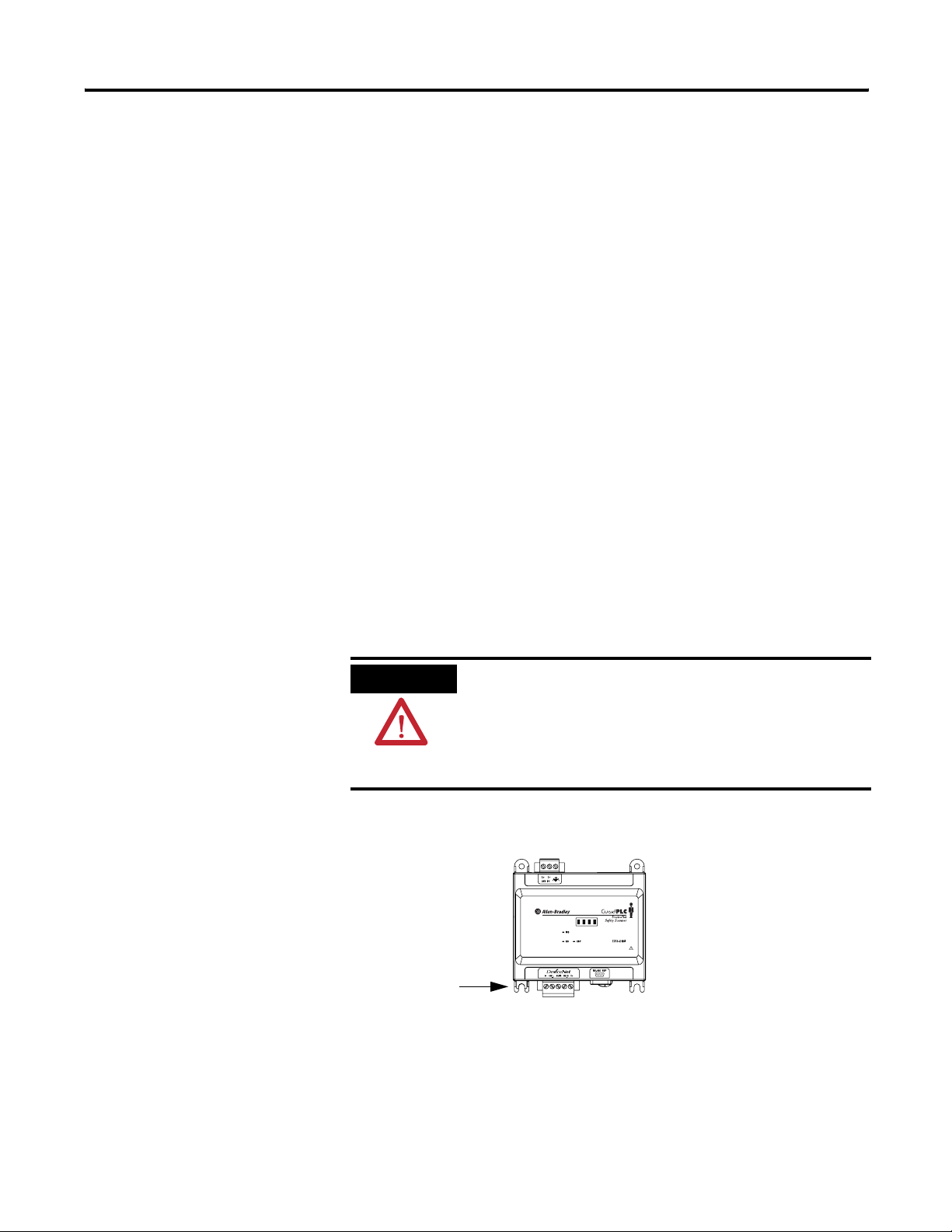
Make Communication Connections
ATTENTION
The scanner has two communication ports. The DeviceNet port is for
communicating on DeviceNet, allowing connections to up to 63
standard DeviceNet nodes and 32 DeviceNet Safety nodes. The HSP
port lets you communicate with a single GuardPLC 1600 or 1800
controller via a 1753-CBLDN cable.
Do not connect or disconnect either communications
cable with power applied to this module or any
device on the network, because an electrical arc can
occur. This could cause an explosion in hazardous
location installations.
Publication 1753-UM002A-EN-P - July 2005
Page 26
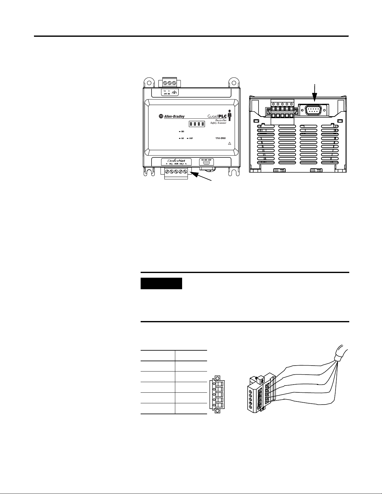
2-6 Install the 1753-DNSI
Front View Bottom View
HSP Port
DeviceNet Safety Port
DeviceNet Connections
Wire the DeviceNet Connector
Use an open-style 5- or 10-position linear plug to connect to the
DeviceNet network.
IMPORTANT
Wire the connector according to the following illustrations:
Connect To
Red Wire V+
White Wire CAN High
Bare Wire Shield
Blue Wire CAN Low
Black Wire V-
For detailed DeviceNet connection information, refer
to the DeviceNet Cable System Planning and
Installation Manual, publication DN-6.7.2. Also refer
to the Industrial Automation Wiring and Grounding
Guidelines, publication 1770-4.1.
DeviceNet cable
5-position
linear plug
10-position
linear plug
D
D
D
D
D
Red
White
Bare
Blue
Black
Publication 1753-UM002A-EN-P - July 2005
Page 27
Install the 1753-DNSI 2-7
Connect to the DeviceNet Network
Attach the connector to the module’s DeviceNet port. Tighten the
screws on the connector to 0.6 to 0.7 Nm (5 to 6 in-lb).
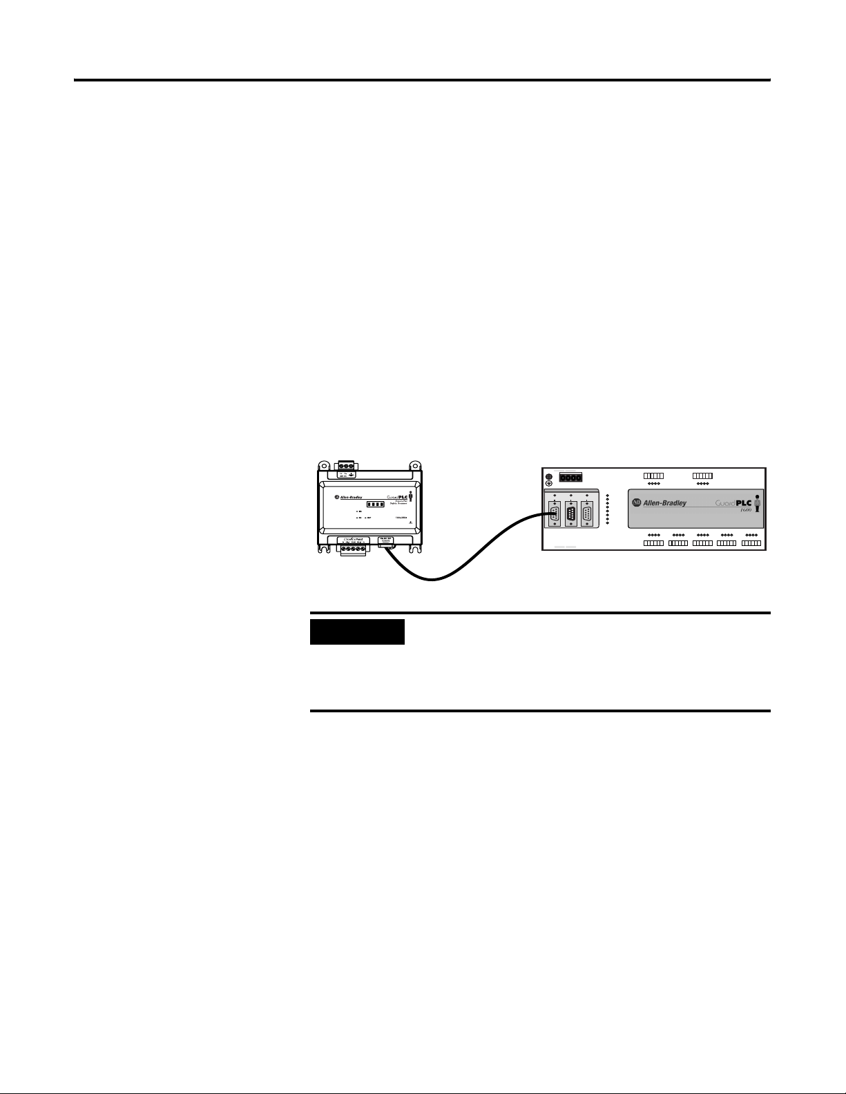
High-speed Safety Protocol (HSP) Connections
The module ships with the cable used to connect its HSP port to the
GuardPLC controller’s COMM3 (ASCII/HSP) port. The minimum bend
radius of the 1753-CBLDN is:
• 30 mm (1.18 in.) when the cable is permanently restrained by
the use of a wire tie, cable trough, or other means.
• 60 mm (2.36 in.) when unrestrained.
IMPORTANT
(—)4(—)
ASCII/HSP
COMM3
GuardPLC Ethernet
10/100 BaseT
3
L-L- L+ L+
24V DC
RS-485
PROFIBUS
COMM2
COMM1
(—)4(—)
3
123456
1234
1L-
24 V DC
RUN
ERROR
PROG
FORCE
FAULT
OSL
BL
1LS+- LS+ LS+ LS+ LS+L-D1234
13 14 15 1617 18
789101112
56
L-DO 2
34
(2A)
11 12
78910
5L- L-DO 6
7 8
(2A)
5L-D1678
9L-D11011 12
19 20 21 2223 24
25 26 27 2829 30
19 20 21 2223 2413 14 15 1623 24 25 26 27 2829 30 31 32 33 3435 36 37 38 3940 4142
1753-CBLDN
The maximum length of the cable connection
between the module and the GuardPLC controller is
0.75 m (2.46 ft). To achieve a SIL 3 rating, you must
use the 1753-CBLDN cable, which is shipped with
the module.
13 L-D11415 16
31 32 33 3435 36
1753-L28BBBM
20 DC Inputs
8 DC Outputs
17 L-D11819 20
37 38 39 4041 42
Publication 1753-UM002A-EN-P - July 2005
Page 28

2-8 Install the 1753-DNSI
Publication 1753-UM002A-EN-P - July 2005
Page 29

Chapter
3
Set Up Your DeviceNet Network
To set up devices on the DeviceNet network, follow the procedures
listed below in order:
Procedure page
1. Connect a Computer to the DeviceNet Network 3-2
2. Commission All Nodes 3-2
3. Browse the Network 3-3
4. Safety Reset (Optional) 3-4
5. Set Passwords (Optional) 3-5
Connect a Computer to the DeviceNet Network
To access a network, either:
• connect directly to the network, or
• connect to a different network and browse to the desired
network via a linking device
TIP
Once you choose a network:
• Install the communication card, if required.
• Determine any network parameters for the computer, such as a
network address.
• Connect the computer to the network using the correct cable.
RSLinx provides online help for configuring
drivers and using linking (bridge) devices.
Configure a Driver for the Network
1. Start RSLinx® software.
2. Click on the Configure Driver button.
1 Publication 1753-UM002A-EN-P - July 2005
Page 30

3-2 Set Up Your DeviceNet Network
3. Pull down the list of Available Driver Types and add the driver
for your network.
For this network Select this driver
RS-232 RS-232 DF1 Devices
EtherNet/IP Ethernet devices
DeviceNet DeviceNet drivers…
4. Configure the driver. The settings you make are dependent
upon the network you choose and whether you are using a
communication card or interface module.
Make Sure the Driver Works
1. Check the Configure Drivers dialog to make sure that the driver
is running.
Commission All Nodes
2. Close the dialog.
3. Open the RSWho window.
4. Double-click on the driver to see the network.
Before you can use RSNetWorx for DeviceNet’s Node Commissioning
tool, your computer and your DeviceNet devices must be connected
to the DeviceNet network.
Use the Node Commissioning tool in RSNetWorx for DeviceNet to set
the node address and/or baud rate of the DeviceNet Safety Scanner
and other DeviceNet devices.
Follow the guidelines on page 1-10 when selecting node addresses for
your DeviceNet network.
TIP
You can set the node address of a DeviceNet Safety
I/O module by setting the rotary switches to a value
between 0 and 63. Or, set the switches to a value
between 64 and 99 to allow the node address to be
set using the Node Commissioning tool in
RSNetWorx for DeviceNet.
Publication 1753-UM002A-EN-P - July 2005
Refer to the DeviceNet Safety I/O Modules User
Manual, publication number 1791DS-UM001, for
information on commissioning 1791DS I/O modules.
Page 31

Set Up Your DeviceNet Network 3-3
To use the Node Commissioning tool:
1. Within RSNetWorx for DeviceNet, select Tools > Node
Commissioning.
2. Click on the Browse button on the Node Commissioning dialog
to select a device by browsing the network.
3. Select the DeviceNet network in the left panel.
4. Select the device you want to commission in the right panel and
click OK.
5. If you want to change the baud rate of the device, select the
desired value.
Browse the Network
IMPORTANT
The baud rate of the device will not update
until the device is power-cycled or reset.
6. On the Node Commissioning dialog, type the new address for
the device and click Apply. A confirmation message tells you if
the operation was successful.
IMPORTANT
To change the node address of a Safety device,
you must first reset the SNN to an uninitialized
state by selecting the SNN and performing a
Safety Reset as described on page 3-4.
1. Browse the network by clicking on the online button .
2. On the Browse for Network dialog, select the DeviceNet
network.
3. Wait for the Browse Network operation to complete. As the
network is browsed, all of the devices on the network will show
up in RSNetWorx for DeviceNet.
4. Verify that all your nodes are visible.
5. Save your project in RSNetWorx for DeviceNet.
Publication 1753-UM002A-EN-P - July 2005
Page 32

3-4 Set Up Your DeviceNet Network
Safety Reset (Optional)
If you need to reset the safety device’s attributes to the out-of-box
default state, you can do so via the Reset Safety Device dialog.
You can reset the attributes shown on the Reset Safety Device dialog
by checking their associated checkbox. Leaving an attribute checkbox
blank preserves that attribute’s setting during the safety reset
operation.
1. Open the Reset Safety Device dialog by clicking on the device in
the RSNetWorx for DeviceNet graphic view and selecting Reset
Safety Device from the Device menu.
2. Check the attributes you want to reset.
Attribute Reset Behavior
Configuration The configuration checkbox is always checked to indicate that
the configuration of the device is erased as a result of any safety
reset action.
Configuration
Owner
Output
Connection
Owner(s)
Password Check this checkbox to reset the device password. You must
Address Check this checkbox to reset the device’s software-configured
Baud Rate Check this checkbox to reset the device’s baud rate to 125 kbps.
Check this checkbox to reset the device’s configuration owner.
The next device that attempts to configure the device following
the safety reset becomes the configuration owner.
Check this checkbox to reset any existing output connection
owners. The next device that accesses an output connection
point following the safety reset becomes the output connection
owner.
know the current device password to reset a password from the
Reset Safety Device dialog.
node Address to 63.
NOTE: If the device’s node Address has been set using DIP
switches, the reset operation has no effect on the node Address.
Publication 1753-UM002A-EN-P - July 2005
Safety Network
Number
NOTE: If the device’s baud rate has been set using DIP switches,
the reset operation has no effect on the baud rate.
Check this checkbox to reset the device’s Safety Network
Number.
Page 33

Set Up Your DeviceNet Network 3-5
3. Click on the Reset button.
4. If the device is Safety-Locked, you are prompted to first unlock
the device.
Set Passwords (Optional)
ATTENTION
5. If you have set a password for the device, enter the password
when prompted.
You can protect safety devices with a password to prevent changes to
the configuration of the device by unauthorized personnel. When a
password is set, the following operations require the password to be
entered:
• download
• Safety-Reset
• Safety-Lock
• Safety-Unlock
Once unlocked, the device cannot be relied
upon to perform safety operations.
You must test and verify the device’s operation
and run the Safety Device Verification Wizard
to Safety-Lock the device before operating the
device in a safety application.
Set or Change a Password
To set a password for a module:
1. Double-click on the module to open the Device Properties
dialog.
2. Select the Safety tab.
Publication 1753-UM002A-EN-P - July 2005
Page 34

3-6 Set Up Your DeviceNet Network
3. Click on the Password… button.
TIP
You can also access the Set Device Password
dialog by either:
• clicking on the module and choosing Set
Password… from the Device menu, or
• right-clicking on the module and selecting
Set Password….
4. Enter the Old Password, if one exists.
5. Enter and confirm the new password.
Passwords may be from 1 to 40 characters in length and are not
case-sensitive. Letters, numerals, and the following symbols may
be used: ‘ ~ ! @ # $ % ^ & * ( ) _ + , - = { } | [ ] \ : ; ? / .
6. Click OK.
Forgotten Passwords
If you forget the password, you can reset it.
Publication 1753-UM002A-EN-P - July 2005
1. On the Safety tab of the Device Properties dialog, click on the
Password… button to open the Set Device Password dialog.
2. Click on the Reset Password… button.
Page 35

Set Up Your DeviceNet Network 3-7
3. Contact Rockwell Automation Technical Support and provide
the device Serial Number and Security Code from the Reset
Password dialog.
4. Enter the Vendor Password obtained from Rockwell Automation
Technical Support on the Reset Device Password dialog and
click OK.
Publication 1753-UM002A-EN-P - July 2005
Page 36

3-8 Set Up Your DeviceNet Network
Publication 1753-UM002A-EN-P - July 2005
Page 37

Chapter
4
Manage the Safety Network Number
Safety Network Numbers assigned to each safety network or network
sub-net must be unique. You must ensure that a unique Safety
Network Number (SNN) is assigned to each DeviceNet network that
contains safety nodes.
Each DeviceNet Safety device must be configured with an SNN. The
combination of SNN and DeviceNet node address provides a unique
identifier for every safety node in a complex industrial network. This
unique identifier prevents data intended for a specific target node
address on one DeviceNet subnet from being mis-routed to a node
with the same node address on a different DeviceNet subnet.
SNN Formats
The Safety Network Number (SNN) can be either software-assigned
(time-based) or user-assigned (manual). These two formats of the SNN
are described in the following sections.
Time-based SNN (Recommended)
In the time-based format, the SNN represents the date and time at
which the number was generated, according to the personal computer
running RSNetWorx for DeviceNet.
1 Publication 1753-UM002A-EN-P - July 2005
Page 38

4-2 Manage the Safety Network Number
Manual SNN
In the manual format, the SNN represents entered values from 1 to
9999 decimal.
Assignment of the SNN
TIP
SNNs can be generated automatically via RSNetWorx for DeviceNet or
manually assigned by the user. Automatically generated SNNs are
sufficient and recommended for most applications.
You can use the Copy button on the Set Safety
Network Number dialog to copy the SNN to the
Windows
®
clipboard.
Automatic (Time-based)
When a new safety device is added to the network configuration, a
default SNN is automatically assigned via the configuration software,
as follows:
• If at least one safety device already exists in the DeviceNet
network configuration, subsequent safety additions to that
network configuration are assigned the same SNN as the lowest
addressed safety device.
• If no other safety devices exist in the DeviceNet network
configuration, a time-based SNN is automatically generated by
RSNetWorx for DeviceNet.
Publication 1753-UM002A-EN-P - July 2005
Page 39

Manage the Safety Network Number 4-3
Manual
The manual option is intended for systems where the number of
DeviceNet subnets and interconnecting networks is small, and where
you might like to manage and assign SNNs in a logical manner
pertaining to their specific application.
IMPORTANT
To set the SNN in a safety device via RSNetWorx for DeviceNet, select
the device in the hardware graphic view and choose Set Safety
Network Number from the Device menu.
IMPORTANT
If you assign SNNs manually, take care to ensure that
system expansion does not result in duplication of
SNN and Node Address combinations.
When you set the SNN, the device is returned to its
factory default configuration.
Set the SNN in All Safety Nodes
A time-based SNN is automatically generated when the first new safety
device is added to the network. Subsequent additions to the network
are assigned the same SNN as the lowest-addressed safety device. This
automatic, time-based SNN is sufficient and recommended for most
applications.
Publication 1753-UM002A-EN-P - July 2005
Page 40

4-4 Manage the Safety Network Number
If you need to set the SNN for a particular device, follow the steps
below:
1. Click on the target device in the hardware graphic view and
select Set Safety Network Number from the Device menu.
2. Select Time-based and click the Generate button, or select
Manual and fill in a Decimal number from 1 to 9999. Click OK.
Publication 1753-UM002A-EN-P - July 2005
TIP
You can use the copy and paste buttons on the
Set Safety Network Number dialog to copy and
paste SNNs between devices and to make a
record of the SNN.
3. Verify that the Network Status LED is rapidly alternating between
red and green on the correct device and click OK.
Page 41

Manage the Safety Network Number 4-5
SNN Mismatch
RSNetWorx for DeviceNet compares the offline SNN to the online SNN
during each browse operation, one-shot or continuous, and during
upload and download operations. If the SNNs do not match,
RSNetWorx for DeviceNet indicates an error with the SNN. The
hardware graphic view displays the ! symbol over the safety device
icon. You can resolve the SNN error from the Safety Network Number
Mismatch dialog, as described on page 4-5.
When online, RSNetWorx for DeviceNet also checks for an SNN
mismatch whenever a safety device’s Device Properties dialog is
selected, either from the Device > Properties menu or by
double-clicking on the device. If an SNN mismatch condition exists,
the Safety Network Number Mismatch dialog is displayed as described
below.
Safety Network Number Mismatch Dialog
This dialog displays the online (device) SNN and the offline (software)
SNN. You can choose to upload the device’s SNN or download the
offline SNN to resolve the mismatch.
TIP
If the device’s SNN has not been initialized, the
Device Safety Network Number field displays the
default SNN: FFFF_FFFF_FFFF. When the device’s
SNN is FFFF_FFFF_FFFF, the Upload button is
disabled.
Publication 1753-UM002A-EN-P - July 2005
Page 42

4-6 Manage the Safety Network Number
SNN and Node Address Changes
If you want to change the address of a safety device, the Safety
Network Number must be uninitialized, or you must first reset the
Safety Network Number.
To reset the SNN:
1. Select the device in the hardware graphic view.
2. From the Device menu, choose Reset Safety Device.
3. Check the Safety Network Number checkbox on the Reset Safety
Device dialog and click on Reset.
Only the attributes selected on the dialog are reset to their
factory default settings. The Safety Reset only affects the safety
device; the configuration in the RSNetWorx project is not lost.
See Safety Reset (Optional) on page 3-4 for more information on
the Safety Reset function.
TIP
After the safety reset, the node address may be
changed in RSNetWorx for DeviceNet by
double-clicking on the safety device’s node
address in the graphic view. After changing the
node address, right-click on the device and
click Download to Device to restore the safety
device’s SNN and configuration.
Publication 1753-UM002A-EN-P - July 2005
Page 43

Chapter
5
Configure DeviceNet Nodes and Connections
To configure standard, safety, and peer-to-peer connections, follow
the procedures listed below in order:
Procedure page
1. Configure DeviceNet Safety I/O Target Nodes 5-2
2. Configure the DeviceNet Safety Scanner’s Safety Connections 5-3
3. Configure DeviceNet Standard Slave I/O Nodes 5-6
4. Configure the DeviceNet Safety Scanner’s Standard Connections 5-6
5. Configure GuardPLC Controller Settings 5-12
Configuration Signature
Each safety device has a unique Configuration Signature, which
identifies its configuration to ensure the integrity of configuration data
during downloads, connection establishment, and module
replacement.
The Configuration Signature is composed of an ID number, a Date
and a Time and is set automatically by RSNetWorx for DeviceNet
when a configuration update is applied to the device. The
Configuration Signature is found on the Safety tab of the Device
Properties dialog.
1 Publication 1753-UM002A-EN-P - July 2005
Page 44

5-2 Configure DeviceNet Nodes and Connections
The Configuration Signature is read during each browse and
whenever the Device Properties dialog is launched while the software
is in Online mode. RSNetWorx for DeviceNet compares the
Configuration Signature in the software (offline) device configuration
file to the Configuration Signature in the online device. If the
Configuration Signatures do not match, you are prompted to upload
the online device configuration or download the software device
configuration to resolve the mismatch.
Configure DeviceNet Safety I/O Target Nodes
1791DS DeviceNet Safety I/O Module Parameters
To configure your module, double-click on the module in the graphic
view or right-click on the module and select Properties.
Safety Input, Output, and Test Parameters
Safety parameters are configured using the Safety Configuration tab on
the Module Properties page.
Publication 1753-UM002A-EN-P - July 2005
Page 45

Configure DeviceNet Nodes and Connections 5-3
Standard Input and Output Parameters
1791DS modules support standard data as well as safety data.
Configure standard input and output parameters using the Parameters
tab on the module properties page.
Configure the DeviceNet Safety Scanner’s Safety Connections
TIP
Configure DeviceNet Safety communications by configuring the
scanner’s connections to safety targets.
On the Safety Connections tab, right-click on the I/O module and
select Add Connections to display all of the available connections.
Other devices may have different configuration
options. Consult the user manual for your device for
more information.
Publication 1753-UM002A-EN-P - July 2005
Page 46

5-4 Configure DeviceNet Nodes and Connections
The Add Safety Connection dialog allows you to configure a
connection.
1. Select the desired connection by choosing the Connection
Name.
2. Select a type of connection, either Multicast (input connections
only) or Point-to-point (input or output connections).
3. Select ‘Configuration signature must match’. This selection
directs the scanner to ensure that the target safety device
contains the correct configuration before opening the safety
connection.
IMPORTANT
If you do not choose ‘Configuration signature
must match’, you are responsible for ensuring
the safety integrity of your system by some
other means.
4. Review the Connection Reaction Time Limit.
The Connection Reaction Time Limit is the maximum age of
safety packets on the associated connection. If the age of the
data used by the consuming device exceeds the Connection
Reaction Time Limit, a connection fault occurs. Adjust the
Connection Reaction Time Limit by changing the RPI or the
Advanced Communication Properties as described in steps 5 and
6.
Publication 1753-UM002A-EN-P - July 2005
5. Set the Requested Packet Interval (RPI).
The RPI specifies the period at which data updates over a
connection. The RPI is entered in 1 millisecond increments, and
the scanner supports a valid range of 5 to 500 ms with a default
Page 47

Configure DeviceNet Nodes and Connections 5-5
of 10 ms. Other target devices may have more limited RPI
constraints. Consult the documentation for each type of target
device to determine its supported range and incremental values.
Modifying the RPI affects the Connection Reaction Time Limit.
For simple timing constraints, setting the RPI is usually sufficient.
However, for more complex requirements, use the Advanced…
button to further adjust the timing values affecting the
Connection Reaction Time Limit as described below.
6. Set the Advanced Safety Connection Properties (if required).
• Timeout Multiplier – The Timeout Multiplier determines the
number of RPIs to wait for a packet before declaring a
connection timeout. This translates into the number of
messages that may be lost before a connection error is
declared.
For example, a Timeout Multiplier of 1 indicates that
messages must be received during every RPI interval. A
Timeout Multiplier of 2 indicates that 1 message may be lost
as long as at least 1 message is received in 2 times the RPI (2
x RPI).
• Network Delay Multiplier – The Network Delay Multiplier
defines the message transport time that is enforced by the
communications protocol. The Network Delay Multiplier
specifies the round trip delay from the producer to the
consumer and back to the producer. You can use the
Network Delay Multiplier to reduce or increase the
Connection Reaction Time Limit in cases where the enforced
message transport time is significantly less or more than the
RPI.
Publication 1753-UM002A-EN-P - July 2005
Page 48

5-6 Configure DeviceNet Nodes and Connections
Configure DeviceNet Standard Slave I/O Nodes
Configure the DeviceNet Safety Scanner’s Standard Connections
To configure your module, double-click on the module in the graphic
view or right-click on the module and select Properties. Navigate
through the available tabs to review and modify the module’s
configuration. Refer to the user manual for the module for additional
information on how to set up the module’s configuration.
To configure the safety scanner for standard communications, you set
up a scanlist and define the memory locations for the standard data of
each device.
Standard Communication Properties
Configure the standard communication properties of the safety
scanner on the Module tab of the Scanner Properties page. You can
use the Module Defaults button to return the safety scanner to the
default settings, which are shown below.
Publication 1753-UM002A-EN-P - July 2005
Interscan Delay
This parameter defines the delay time the scanner uses between scans
of the DeviceNet network. If you have slave devices configured for
Polled behavior in the scanner’s scanlist, Interscan Delay (ISD) defines
the amount of time the scanner waits between writing outputs to the
polled devices.
Page 49

Configure DeviceNet Nodes and Connections 5-7
Increasing the ISD time causes a longer network scan, which
adversely affects overall input-to-output performance. However, the
increase allows lower priority messages to get more network access.
These lower priority messages include those used to do network
browsing and configuration upload and download functions. So, if
these network functions are sluggish on your system, increasing the
ISD time is one way to make more bandwidth available for lower
priority messages.
In addition, if the last node in your scan list produces a large amount
of polled data, you may want to increase the ISD time to ensure that
the entire response is received before the next poll request is sent to
that node.
Foreground to Background Poll Ratio
Devices set for polled behavior can be polled on every I/O scan
(foreground) or they can be polled less frequently (background).
Setting a device for foreground or background behavior is done when
you configure each device on the Scanlist tab, from the Edit I/O
Parameters dialog. A ratio of 2 means that any nodes included on the
background list are polled every other scan cycle. A ratio of 3 means
they are polled on every third cycle, etc.
Advanced Module Settings
Clicking on the Advanced… button lets you to set the Expected
Packet Rate (EPR) and the Transmit Retries as described below.
• Expected Packet Rate (EPR) – When the scanner opens a polled
or strobed I/O connection, it uses this value as a maximum
timeout (Expected Packet Rate) with the device. If the device does
not receive a packet from the scanner within 4 times the EPR
value, the slave device drops the connection. If the scanner does
not receive a packet from the slave within 4 times the EPR value,
it drops the connection and periodically attempts to reopen the
connection.
Publication 1753-UM002A-EN-P - July 2005
Page 50

5-8 Configure DeviceNet Nodes and Connections
When a standard connection is dropped, status bits in the
scanner identify that the slave is not online. Slave behavior
when a connection is dropped is a function of the slave device.
If the slave is an I/O device, the standard outputs will be
cleared, held at last state, or set to a fault condition (refer to the
slave device’s documentation for actual I/O behavior when a
connection is dropped).
When an input connection is dropped, the scanner sets the
corresponding data in the data tables sent to the GuardPLC
controller via the HSP connection to the safety state (0).
The EPR default value is 75 milliseconds.
IMPORTANT
Changing the EPR number should be done
carefully because it effects how long it takes the
scanner to detect a missing device.
• Transmit Retries – Transmit Retries specifies the number of times
the scanner attempts to retransmit a change of state or cyclic
message that has not been acknowledged by the slave device
before dropping the connection.
Create a Scanlist
The scanlist defines the standard devices (nodes) with which the
scanner is configured to exchange I/O data.
Publication 1753-UM002A-EN-P - July 2005
Page 51

Configure DeviceNet Nodes and Connections 5-9
Available Devices
These are the devices on the network that have the ability to be
standard slave I/O devices. The DeviceNet Safety Scanner, as well as
any other scanners that have been configured to support a standard
slave-mode interface will also appear in this list. Slave-capable devices
do not have to be used as slave I/O by a scanner. They may
alternately be used as slave I/O by another scanner on the same
network, or they may have dual functionality.
Scanlist
These devices have been assigned to be slave I/O to this scanner. The
outputs of a slave device on DeviceNet can only be owned by one
master at a time. Data mappings for each device in the scanlist are
configured using the input and output tabs. Add an available device
by selecting the device and clicking on the add arrow >. The
double-arrow >> adds all the available devices to the scanlist.
It is not necessary to enter safety nodes into the safety scanner’s scan
list. All safety connections are configured on the Safety Connections
tab. You only need to put a safety device into the safety scanner’s
scanlist if you are communicating with that device via a standard
connection and exchanging standard data with it.
Automap on Add
Automap allows a slave’s I/O to be automatically mapped into the
scanner’s input or output image tables when the slave device is added
to the scanlist. DO NOT check this box if you intend to map a slave
device into a particular input or output memory location.
Edit I/O Parameters
These parameters will vary depending upon the slave device.
Information on configurable parameters is usually provided in the
device’s documentation.
Electronic Key
The electronic key is used to ensure that a particular slave device
always matches the intended device when the scanner initiates a
connection to it. When one of the devices in the Scanlist section is
highlighted, these boxes may be checked to indicate to what extent
the key parameters must match the actual device on the network. A
match of just Device Type can be selected or the additional
parameters of Vendor ID and Product Code may be incrementally
added.
Publication 1753-UM002A-EN-P - July 2005
Page 52

5-10 Configure DeviceNet Nodes and Connections
Should the scanner detect a mismatch with any of the key parameters
checked, an Electronic Key failure (status code 73) will occur for that
slave device and the scanner will abort the connection establishment
process.
Configure Standard Inputs
The Input tab lets you define how standard data from all of the
scanner’s slave devices are mapped into the input image of the
controller.
Publication 1753-UM002A-EN-P - July 2005
The graphical window at the top shows each device’s node number,
catalog number, type of connection that is used between the scanner
and the slave device (strobed, polled, cyclic or change of state), the
amount of data that will be exchanged (in bytes), and the location of
the data within the controller’s scanner’s standard input image.
Page 53

Configure DeviceNet Nodes and Connections 5-11
Configure Standard Outputs
The Output tab screen allows you to define how data from the
scanner is mapped to the outputs of the slave devices.
The graphical window at the top shows each devices node number,
catalog number, type of connection that is used between the scanner
and the slave device (strobed, polled, cyclic or change of state), the
amount of data that will be exchanged (in bytes), and the location of
the data within the controller’s scanner’s standard output image.
Publication 1753-UM002A-EN-P - July 2005
Page 54

5-12 Configure DeviceNet Nodes and Connections
Configure GuardPLC Controller Settings
Use the GuardPLC tab to configure the scanner’s HSP connection
parameters.
Controller ID
The Controller ID (SRS) uniquely identifies a particular GuardPLC
controller within a network of controllers. Its use ensures that this
configuration is applied to the correct controller. Specify the
Controller ID of your selected GuardPLC controller, or this will
automatically be provided when you associate the scanner and
controller as described in Chapter 7.
Scanner ID
The scanner ID is a read-only value which uniquely identifies the
scanner and is required to connect the GuardPLC controller to the
scanner. The scanner ID is automatically generated by RSNetWorx for
DeviceNet using the SNN and DeviceNet address of the scanner. It is
exported in the Scanner Signals file and is viewable in the associated
RSLogix Guard PLUS! project.
HSP Signature
The HSP Signature is a read-only value that is unique to each layout of
the signals within the data exchanged between the GuardPLC
controller and the 1753-DNSI. The HSP Signature is calculated based
on the scanner’s configured safety and standard connections and any
target connections defined in RSLogix Guard PLUS!. It is passed to
RSLogix Guard PLUS! via the Scanner Signals File. The HSP signature
changes only when a modification occurs in the layout of the signals
exchanged between the controller and scanner.
Publication 1753-UM002A-EN-P - July 2005
Page 55

Configure DeviceNet Nodes and Connections 5-13
Scanner Receive Timeout
The Scanner Receive Timeout is the amount of time (in milliseconds)
that the scanner waits for a request from the GuardPLC controller
before timing out the HSP connection. If the scanner does not receive
a message from the GuardPLC controller within this time, all output
connections are transitioned to the idle state, causing the safety
outputs to transition to the safety state and standard outputs to follow
the behavior dictated by their configuration.
Set the Scanner Receive Timeout equal to the Watchdog Timeout
specified on the Properties dialog of the controller resource in
RSLogix Guard PLUS! Hardware Management. Refer to the GuardPLC
Controller Systems User Manual, publication number 1753-UM001, for
information on setting the Watchdog Time.
Max. Scanner Response Time
The Max Scanner Response Time is the maximum amount of time (in
milliseconds) allotted for the scanner to process an HSP request from
the controller, and then format and send a proper response. If the
scanner cannot respond within this time frame, then all output
connections transition to the idle state, causing the safety outputs to
transition to the safety state and standard outputs to follow the
behavior dictated by their configuration.
The Max Scanner Response Time should be set to a value that
includes the maximum observed statistical scanner response time over
several hours of operation, plus a Margin of Safety equal to 3 ms or
10% of the maximum observed scanner response time. When online,
you can view the Minimum, Maximum, and Average Observed
Scanner Response Times by selecting the Statistics… button.
Publication 1753-UM002A-EN-P - July 2005
Page 56

5-14 Configure DeviceNet Nodes and Connections
Publication 1753-UM002A-EN-P - July 2005
Page 57

Chapter
6
Create a GuardPLC Project with High-Speed
Safety Protocol
To configure the GuardPLC controller to communicate with the
DeviceNet Safety Scanner for GuardPLC Controllers, follow the
procedures listed below in order:
Procedure page
1. Create or Open a GuardPLC Project 6-1
2. Add High-Speed Safety Protocol to the GuardPLC Controller Resource 6-3
3. Review the GuardPLC Controller’s Communication Settings 6-5
Create or Open a GuardPLC Project
For detailed information on creating a GuardPLC controller project in
RSLogix Guard PLUS!, refer to the GuardPLC Controller Systems User
Manual, publication number 1753-UM001.
TIP
1. In RSLogix Guard PLUS!, either open an existing GuardPLC 1600
or GuardPLC 1800 controller project or create a new project by
selecting Project>New from the main menu.
If the project is new, enter the name of the project in the Object
Name field and click OK. RSLogix Guard PLUS! automatically
creates a single resource in a new project.
To optimize performance and minimize compilation
time, create and store your projects on a local drive.
TIP
You can rename the controller Resource in the
Project Management window by right-clicking
on the Resource and selecting Rename from
the context menu.
1 Publication 1753-UM002A-EN-P - July 2005
Page 58

6-2 Create a GuardPLC Project with High-Speed Safety Protocol
If you are opening an existing project, created in a prior version
of RSLogix Guard PLUS!, the software automatically converts the
project to the new version.
TIP
Make a backup copy of your existing RSLogix
Guard PLUS! project before opening it in the
latest version, since the latest version
automatically converts the existing project.
2. In the Hardware Management dialog, right-click on the
controller Resource and select Properties.
Publication 1753-UM002A-EN-P - July 2005
3. Specify the controller type (GuardPLC 1600 or GuardPLC 1800
controllers only for HSP) and enter the System ID (SRS) of the
controller. If you do not know the SRS, you need to connect the
controller directly to your computer’s Ethernet port and use the
Communication Settings dialog to retrieve the SRS. See step 1 on
page 6-5.
Page 59

Create a GuardPLC Project with High-Speed Safety Protocol 6-3
Add High-Speed Safety Protocol to the GuardPLC Controller Resource
To add High-Speed Safety Protocol (HSP) to your GuardPLC
controller:
1. Right-click on the Protocols folder under your Resource and
select New>HSP Protocol.
2. Configure HSP communications. Right-click on HSP Protocol
and select Properties.
The Controller Receive Timeout is the amount of time that the
controller waits to receive an HSP response from the scanner
before closing the HSP connection.
Controller Resend Timeout is the amount of time that the
controller waits for the acknowledgement of a message before it
resends it.
Publication 1753-UM002A-EN-P - July 2005
Page 60

6-4 Create a GuardPLC Project with High-Speed Safety Protocol
Use the following guidelines when setting the Controller Receive
Timeout and Controller Resend Timeout:
• In environments where no HSP retries are required, set the
Controller Receive Timeout to the amount of time required
for the controller to send the HSP request, for the scanner to
process the request, and for the scanner to send a response
back to the controller. This value can be determined by
observing the Response Time values displayed on the HSP
protocol tab of the Resource Control Panel.
Set the Controller Receive Timeout to be greater than or equal
to the maximum value reported plus a margin of safety (3 ms
or 10% of the maximum value reported). The Controller
Resend Timeout should be set to zero.
• In electrically noisy environments, configuring retries on the
HSP link may be required. Set the Controller Resend Timeout
to be equal to or greater than the Max Response Time value
reported on the HSP Protocol tab of the Resource Control
Panel plus a margin of safety (3 ms or 10% of the maximum
value reported). To enable a single retry, the Controller
Receive Timeout must be 2 times the Controller Resend
Timeout. To enable 2 retries, the Conroller Receive Timeout
must be 3 times the Controller Resend Timeout.
• The controller’s Communications Time Slice, found on the
Properties dialog of the controller Resource, must be greater
than the Controller Receive Timeout to enable proper HSP
operation. If other protocols are in use on the controller
Resource, then the Communications Time Slice should be
increased to accommodate their use in conjunction with HSP.
The Maximum Communication Time Slice setting on the
Device Properties page should be set to the Maximum
Communication Time Slice observed on the Control Panel’s
Statistics tab plus a margin of safety (6 ms or 10% of the
maximum value reported).
Publication 1753-UM002A-EN-P - July 2005
TIP
The Controller Id, Scanner Id and Scanner
Receive Timeout values are shown here for
reference. These values are set following a
successful Scanner Signals File (.ssf) import
process. For the import process to succeed, the
Controller Id must match the System ID (SRS)
of the controller Resource.
Refer to the GuardPLC Controller Systems User manual,
publication 1753-UM001, for more information on configuring
communications for GuardPLC controllers.
Page 61

Create a GuardPLC Project with High-Speed Safety Protocol 6-5
Review the GuardPLC Controller’s Communication Settings
1. Retrieve or confirm the communication settings by selecting
Communication Settings from the Online menu.
a. If you know the current IP Address, SRS and Administrator
password, you can fill in the IP Address and SRS and select
Get. This retrieves and confirms the communication settings.
If you want to modify the current settings, see step 2.
b. If you do not know the current settings, you must connect
your GuardPLC controller directly to your computer’s
Ethernet port and fill in the last three digits of the controller’s
MAC Address. The MAC Address is located on a label above
the controller’s lower Ethernet ports. Select Get to retrieve the
current settings.
TIP
2. You can now enter the desired settings for the IP Address and
SRS.
3. To apply the new settings to the controller, click on either the
Set via IP or Set via MAC buttons, depending on whether you
use the IP Address or MAC Address in step 1.
4. Click the ->Project button to send the settings to the project.
The MAC Address lookup function can fail
if there is an Ethernet switch between the
PC running RSLogix Guard PLUS! and the
GuardPLC controller.
Publication 1753-UM002A-EN-P - July 2005
Page 62

6-6 Create a GuardPLC Project with High-Speed Safety Protocol
Publication 1753-UM002A-EN-P - July 2005
Page 63

Chapter
7
Associate the Scanner and Controller and
Download the DeviceNet Network
Configuration
To allow the scanner and the controller to communicate you can
associate their configurations using the Automatically Update Signals
feature or you can manually manage the association. Both options are
found on the GuardPLC tab of the Scanner Properties page in
RSNetWorx for DeviceNet.
Scanner Signals File
TIP
Once you’ve made the association between the scanner and
controller, download the DeviceNet network configuration.
This chapter covers:
• the Scanner Signals File
• the Target Connections File
• the Automatically Update Signals procedure
• the manual association procedure
• downloading the DeviceNet network configuration
The Scanner Signals File (.ssf) contains standard and safety level input
and output data. RSNetWorx for DeviceNet creates a Scanner Signals
File to define the layout of the data tables exchanged with the
controller via HSP, including detailed signal information
HSP Signature. The data table contents include the data areas
allocated to the DeviceNet I/O nodes to which the scanner connects,
as well as data areas allocated to RSLogix Guard PLUS! application
signals that are identified in the controllers Target Connections file
(.tcf) and made available to DeviceNet peers that connect to the
scanner.
We recommend using the Automatically Update
Signals feature because it eliminates the need to
manually import signals and export connections
after every configuration change.
(1)
and the
(1) Not all standard I/O devices may provide these detailed I/O assembly definitions. Contact your device vendor
for updated EDS files.
Standard devices that do not support these detailed I/O assembly definitions may include an UNKNOWN data
type. Use the Define Data button on the Standard Data, Signal Connections screen in RSLogix Guard PLUS! to
define these data types.
1 Publication 1753-UM002A-EN-P - July 2005
Page 64

7-2 Associate the Scanner and Controller and Download the DeviceNet Network Configuration
The Scanner Signals File separates data transferred on safety
connections from data transferred over standard connections.
Signals created in the RSLogix Guard PLUS! Signal Editor can be
assigned to scanner I/O data signals, allowing them to be used by the
GuardPLC application logic.
Target Connections File
Automatically Update Signals
RSLogix Guard PLUS! generates the Target Connections File (.tcf) to
inform RSNetWorx for DeviceNet which application signals should be
exposed on the scanner’s DeviceNet slave mode or target interfaces.
As described in the Scanner Signals Files section, RSNetWorx for
DeviceNet chooses locations for these target signals within the data
tables that are exchanged over the HSP connection. See ‘How Data
Tables Work’ on page 1-4 for more information on how safety and
standard data is organized in a GuardPLC system that uses the safety
scanner.
The simplest way to associate the 1753-DNSI and the GuardPLC
controller is to select Automatically Update Signals on the safety
scanner’s GuardPLC tab. This option is only available when RSLogix
Guard PLUS! and RSNetWorx for DeviceNet are installed on the same
computer.
1. Open the Device Properties dialog by double-clicking on the
scanner you want to associate.
2. Select the GuardPLC tab.
Publication 1753-UM002A-EN-P - July 2005
3. Select the Automatically Update Signals option.
Page 65

Associate the Scanner and Controller and Download the DeviceNet Network Configuration 7-3
4. Select your RSLogix Guard PLUS! project.
a. If you have multiple RSLogix Guard PLUS! projects, use care
to select the correct one.
TIP
Only RSLogix Guard PLUS! projects that
have at least one resource with HSP
communications enabled can be selected.
b. If you have multiple controller resources in your RSLogix
Guard PLUS! project, RSNetWorx prompts you to select the
correct resource.
5. RSNetWorx for DeviceNet automatically updates the Controller
ID and imports the Target Connections File from the associated
RSLogix Guard PLUS! project.
6. Click OK to establish the association.
Whenever the safety scanner configuration changes, RSNetWorx for
DeviceNet automatically generates or updates the Scanner Signals file.
TIP
If RSLogix Guard PLUS! is open to the associated
project, then it automatically imports the Scanner
Signals file.
Publication 1753-UM002A-EN-P - July 2005
Page 66

7-4 Associate the Scanner and Controller and Download the DeviceNet Network Configuration
Manually Associate the Scanner and Controller
If you manually associate the scanner and controller, you must repeat
this procedure whenever you make a change to the DeviceNet
connections.
To manage the association between the safety scanner and the
GuardPLC controller manually:
1. On the GuardPLC tab of the Device Properties dialog, verify that
the Controller ID matches the GuardPLC controller to which you
want the scanner associated.
2. Click on the Export Scanner Signals… button.
Publication 1753-UM002A-EN-P - July 2005
3. Save the Scanner Signals file. The Scanner Signal file’s extension
is .ssf.
Page 67

Associate the Scanner and Controller and Download the DeviceNet Network Configuration 7-5
4. Import the Scanner Signals file into your GuardPLC project.
a. In RSLogix Guard PLUS! Hardware Management, right-click
on the instance of the HSP protocol for your GuardPLC
controller resource and select Import Scanner Signals…
Download the DeviceNet Network Configuration
b. Browse to the correct .ssf file and select Open.
Before you download, you must go online to the DeviceNet network
using RSNetWorx for DeviceNet. Your computer and the devices you
wish to communicate with must be connected to the DeviceNet
network.
When you go online to a DeviceNet network, RSNetWorx for
DeviceNet browses the network one time and shows you the devices
on the network. It does not read (upload) or change (download) the
parameters of any of the devices.
The graphics representation of the network created by the browse
operation remains static. It does not automatically update to show
changes since the last browse, unless the Continuous Browse…
option is selected.
Publication 1753-UM002A-EN-P - July 2005
Page 68

7-6 Associate the Scanner and Controller and Download the DeviceNet Network Configuration
1. Go online by selecting the online button.
2. Browse to the DeviceNet network and click OK at the prompt.
During each browse operation, RSNetWorx for DeviceNet reads
the following attributes of each device.
Safety Attribute Description
SNN and Node Address
Combination
Configuration Signature RSNetWorx for DeviceNet compares the
Safety-Lock If the device is Safety-Locked, its configuration
The node address and SNN stored in the
RSNetWorx for DeviceNet configuration file must
match the node address and SNN of the online
device. If the SNNs do not match, the device
enters the SNN error state. See page 4-5 for
information on resolving an SNN mismatch error.
Configuration Signature in its configuration file
with the Configuration Signature in the online
device.
cannot be modified without first unlocking the
device.
3. Download your configuration to the network by selecting the
device and choosing Download to Device from the Device
menu or by right-clicking on the device and selecting Download
to Device.
Publication 1753-UM002A-EN-P - July 2005
Page 69

Associate the Scanner and Controller and Download the DeviceNet Network Configuration 7-7
4. Confirm your intent to download by clicking Yes.
If a device is password-protected, RSNetWorx for DeviceNet
prompts you to enter the password for each protected device.
If a device is Safety-Locked, you must first unlock the device and
then download.
IMPORTANT
TIP
If you Safety-Unlock a device, you must run
the Safety Device Verification Wizard to
re-verify and Safety-Lock the device before
operating the device in your safety system.
If none of your devices are password-protected or
safety-locked you can select Download to Network
from the Network menu to download your
configuration to the network. However, this process
skips devices that are password-protected or
safety-locked.
Publication 1753-UM002A-EN-P - July 2005
Page 70

7-8 Associate the Scanner and Controller and Download the DeviceNet Network Configuration
Publication 1753-UM002A-EN-P - July 2005
Page 71

Chapter
Develop Your GuardPLC Application
To define your application signals and use them in your program
logic, follow the procedures listed below in order:
Procedure page
1. Define Signals for Your GuardPLC Application 8-1
2. Create Application Program Logic 8-4
3. Save and Compile Application Logic 8-4
4. Download the Project to the Controller 8-4
8
Define Signals for Your GuardPLC Application
Once the association between the scanner and controller is
established, you can configure signals which allow you to use the
safety or standard data in your GuardPLC application.
Review the guidelines for creating a distinction between safety and
standard signals on page 1-4.
Define Signals for Safety Data
1. In your RSLogix Guard PLUS! project, right-click on the HSP icon
and choose Connect Signals > Safety Data.
1 Publication 1753-UM002A-EN-P - July 2005
Page 72

8-2 Develop Your GuardPLC Application
2. Open the Signal Editor by selecting Editor from the Signals
menu.
3. Create a new signal by selecting New Signal or clicking in an
empty signal Name field.
4. With the Safety Data, Signal Connections dialog visible and the
Signal Editor dialog open, drag your application signals to the
desired device data signals.
Publication 1753-UM002A-EN-P - July 2005
Page 73

Develop Your GuardPLC Application 8-3
Configure HSP Connection
The safety scanner closes the HSP connection whenever either an HSP
error occurs or the safety scanner diagnostic reports an error.
Individual DeviceNet safety or standard connection errors do not
cause the HSP connection to close. In the case of a faulted DeviceNet
connection, any input data associated with that connection is forced
to zero before being transmitted to the GuardPLC controller over HSP.
Your GuardPLC application logic can control the operation of the HSP
connection, by writing a value to the signal associated with the HSP
Connection Control Word.
To connect a signal to the HSP Connection Control Word, right-click
on your HSP protocol in the RSLogix Guard PLUS! Hardware
Management window and choose Connect Signals>HSP Data.
The following table describes the possible mode settings for the HSP
connection.
Connection
Control Word
Value
0x8000 Disabled HSP communication disabled.
0 Autoconnect If communication is lost, open it automatically in
0x100 Toggle_Mode_0 If the connection is lost, do not reopen it until
0x101 Toggle_Mode_1 If the connection is lost, do not reopen it until
Mode Description
the next cycle.
Toggle_Mode_1 is written.
Toggle_Mode_0 is written.
Publication 1753-UM002A-EN-P - July 2005
Page 74

8-4 Develop Your GuardPLC Application
Create Application Program Logic
Save and Compile Application Logic
Download the Project to the Controller
Create application program logic using the signals you defined.
Drag and drop the application signals, which are now connected
(mapped) to DeviceNet data signals, into the appropriate application
Type Instances and create your program logic.
Save and compile your application logic.
Compiling the application logic and controller hardware configuration
results in a high-integrity computation of the HSP signature.
Refer to the GuardPLC Controller Systems User Manual, publication
number 1753-UM001, for details on creating, saving, and compiling
program logic.
Place the Controller in Stop Mode (if necessary)
Before you can download to the GuardPLC controller, the controller
must be in Stop mode. In RSLogix Guard PLUS! Hardware
Management, left-click on the stop icon on the Control Panel and
confirm the action by selecting Yes to the warning prompt.
Publication 1753-UM002A-EN-P - July 2005
Download the Project
In RSLogix Guard PLUS! Hardware Management:
1. Right-click on the controller resource.
2. Select Online > Control Panel.
3. Fill in your user name and password on the login screen. The
default username is Administrator with no password. Click OK.
TIP
Enter Ctrl-A to automatically fill in the default
username and access type.
Page 75

Develop Your GuardPLC Application 8-5
4. Click the download icon and confirm the action by selecting Yes
to the warning prompt.
TIP
If this is the first time the application has been
downloaded, you may want to adjust the timing
parameters artificially high and allow the project to
run for several hours. This lets you gather statistics
on the system’s operation before refining the timing
parameters.
Set this parameter Using
Controller Resend Timeout
Controller Receive Timeout
Communications Time Slice
Watchdog Time
Safety Time
Scanner Receive Timeout
Max. Scanner Response Time
Individual Safety/Standard
connection Timing parameters
RSLogix Guard PLUS! Hardware
Management
RSNetWorx for DeviceNet
Publication 1753-UM002A-EN-P - July 2005
Page 76

8-6 Develop Your GuardPLC Application
Publication 1753-UM002A-EN-P - July 2005
Page 77

Chapter
9
Verify Your DeviceNet Safety Configuration
IMPORTANT
The Safety Device Verification Wizard, accessed from RSNetWorx for
DeviceNet, guides you through the process of verifying the
configuration of your safety devices and provides the means for
Safety-Locking those devices. The verification process includes upload
and comparison of the configuration stored in the device and the
configuration stored in the RSNetWorx for DeviceNet configuration
file. The configuration is displayed in a report to facilitate visual
verification and record keeping.
IMPORTANT
Before running the Safety Device Verification Wizard,
you should browse and upload your network and
test the safety devices on your network to ensure
that they are operating properly. You must fully test
your application prior to safety-locking your devices.
Refer to the GuardPLC Controller Systems Safety
Reference Manual, publication number 1753-RM002
for information on verification testing for safety
applications.
Some devices may not support verification by the
Safety Device Verification Wizard. Consult the user
documentation to determine the method required for
verifying these devices.
Start the Safety Device Verification Wizard
Determine if Devices Can Be Verified
1 Publication 1753-UM002A-EN-P - July 2005
To run the Safety Device Verification Wizard, select Network > Safety
Device Verification Wizard. The Welcome page, which describes the
verification process, appears.
Click Next.
When the Safety Device Verification Wizard browses the network, it
checks the safety status of the devices on the network to determine if
the devices can be verified.
If any devices are in a state that prevents the wizard from continuing
the verification process, the ‘Unable to verify the listed devices’ page
Page 78

9-2 Verify Your DeviceNet Safety Configuration
appears listing those devices and their current status, including a
device icon overlaid with a status icon.
Status
Missing The device is part of the network configuration, but was
Mismatch The device identity in the network configuration does
Unknown The device is in the configuration, but has not been
Safety Network
Number Error
Signature
Mismatch
Safety Locked The device is already locked.
Icon
Overlay
none The configuration signature in the device does not
Description
not found during the browse operation.
not match the identity of the online device.
detected on the network yet.
The Safety Network Number in the device is either
invalid or does not match the Safety Network Number
for the device in the RSNetWorx for DeviceNet
configuration file.
match the configuration signature in the RSNetWorx for
DeviceNet configuration file.
To return to RSNetWorx for DeviceNet so that you can correct the
status of the indicated devices, close the Safety Device Verification
Wizard by clicking on Cancel.
Publication 1753-UM002A-EN-P - July 2005
To skip the devices listed and continue the verification process for
other safety devices on the network, click Next.
Page 79

Verify Your DeviceNet Safety Configuration 9-3
Select Devices to Verify
Choose which devices to verify using the checkboxes in the Verify
column of the Verify Safety Device Configuration dialog. You can
select only the devices whose status is ‘Ready to be verified’.
If the Show all safety devices checkbox is checked, the dialog lists all
of the safety devices on the network and shows their current status. If
it is unchecked, which is the default, only devices with the following
status are shown:
• Ver if y FAI LE D
• Ready to be verified
• Verify not supported
These states are described in the following table.
Status Description
Verify FAILED The upload and compare operation indicated that the configuration
in the device does not match the configuration in the RSNetWorx
for DeviceNet configuration file.
Ready to be verified The device is not Safety-Locked and can be selected for
verification.
Verify not supported The device is not Safety-Locked, but the device does not support
verification via the Safety Device Verification Wizard. Consult your
user documentation for information on how to verify this device.
Once the device has been verified, it can be Safety-Locked by the
wizard.
Publication 1753-UM002A-EN-P - July 2005
Page 80

9-4 Verify Your DeviceNet Safety Configuration
Click on Next to begin the upload and compare process.
TIP
If you click on Next without selecting a device to
verify, the wizard checks whether any devices were
verified or are ready to be locked in this execution of
the wizard.
If Then the wizard displays
devices were verified the Review page listing those devices
devices are ready to be
Safety-Locked
no devices were verified the Finish page
no devices are ready to
be Safety-Locked
the Lock page listing those devices
the Finish page
Publication 1753-UM002A-EN-P - July 2005
Page 81

Verify Your DeviceNet Safety Configuration 9-5
Review the Safety Device Verification Reports
The Review page displays safety devices with status of either ‘Verify
FAILED’ or ‘Ready to be Safety Locked’.
1. Click on the Review hyperlink in the Report column to launch
the device’s HTML report in your default browser.
2. Click the Review All button to generate an HTML verification
report for all of the devices listed.
TIP
3. Review and print the verification reports for your records.
IMPORTANT
If a device’s status is ‘Verify FAILED’ more
information is provided in the verification failure
report.
You must review the device configurations and
record the configuration signatures prior to
operating a safety application.
Publication 1753-UM002A-EN-P - July 2005
Page 82

9-6 Verify Your DeviceNet Safety Configuration
Lock Safety Devices
IMPORTANT
1. Choose which devices to Safety-Lock by selecting the checkbox
in the Lock column for each device that is ready to be
Safety-Locked.
Before you lock your safety device configurations,
you must perform all of the verification steps
required for your application.
2. You must check the acknowledgement box before the locking
process can continue.
3. Click Next.
4. The wizard performs a final comparison of the configuration
signature in each safety device to its configuration signature in
RSNetWorx for DeviceNet before locking the device.
5. If any of the selected devices are password-protected, you will
be prompted to enter the password for that device.
If you want to skip the device and allow the locking process to
continue for other devices, click on Skip.
Publication 1753-UM002A-EN-P - July 2005
Page 83

Verify Your DeviceNet Safety Configuration 9-7
View the Safety Device Verification Wizard Summary
Before closing, the wizard displays a summary of all the safety devices
that were Safety-Locked, the number of safety devices that still need
to be Safety-Locked, and lets you display the verified and
Safety-Locked state of all of the safety devices on the network.
Click on Finish to close the wizard.
Publication 1753-UM002A-EN-P - July 2005
Page 84

9-8 Verify Your DeviceNet Safety Configuration
Publication 1753-UM002A-EN-P - July 2005
Page 85

Chapter
10
Monitor Status
To assist you in monitoring the status of devices on the DeviceNet
Safety network, the DeviceNet Safety Scanner provides:
• LED status indicators
• an alphanumeric status display.
You can also monitor the status of HSP, DeviceNet Safety and standard
connections, and the DeviceNet interface via connection status bits
and the corresponding GuardPLC application signals.
LED Status Indicators
The scanner has 3 LEDs which allow you to monitor module,
DeviceNet network, and High Speed Protocol (HSP) status.
LED Color/State Description
Off No power.
Green, On Operating under normal conditions.
Green, Flashing Device is Idle.
Module
Status
Network
Status
Red, Flashing A recoverable fault exists.
Red, On An unrecoverable fault exists.
Red/Green, Flashing Self-tests in progress or the device needs
commissioning due to configuration or unique node
identifier missing, incomplete, or incorrect.
Off Device is not online or may not have DeviceNet network
power.
Green, On Device is online; one or more connections are
established.
Green, Flashing Device is online; no connections established.
Red, Flashing Communication timeout.
Red, On Communication failure. The device has detected an
error which has prevented network communication.
Red/Green, Flashing The SNN is being set.
1 Publication 1753-UM002A-EN-P - July 2005
Page 86

10-2 Monitor Status
LED Color/State Description
Off The module has not received any messages on the serial
interface.
Green, On The module is transmitting data over the serial
HSP
Status
Green, Flashing The serial interface is ready for communication, but the
Red, Flashing The connection to the controller was lost after being
communication interface.
controller is sending messages that do not match the
safety scanner’s current configuration.
established at least once since power up.
Alphanumeric Display
Display Description
A#xx ‘xx’ is the MAC ID of the scanner. A status string follows.
IDLE The scanner is in idle mode.
At Power Up
When you apply power to the 1753-DNSI safety scanner, check the
scanner’s alphanumeric display to determine if the module is
operating properly. It displays the following:
• firmware revision
• MAC ID
• DeviceNet communication rate
During Operation
Following power up, the alphanumeric display on the safety scanner
displays the following information:
RUN The scanner is in run mode.
Duplicate
Node Failure
Publication 1753-UM002A-EN-P - July 2005
The address of the scanner is already in use by another device on the network. Change the
address to an unused address.
Page 87

Display Description
Bus Off
A bus off condition (communication problem) exists.
Detected
1. Cycle power to the device or disconnect and reconnect the DeviceNet cable.
2. Make sure all devices are at the same communication rate.
3. Make sure a short-circuit does not exist between the CAN line and a power or
shield line.
4. Check for any of the following sources of noise:
• Close proximity to a high voltage power cable
• Improper or no termination resistor
• Improper grounding
5. Check for a device that is producing noise or inappropriate data on the network.
Monitor Status 10-3
No Network
Power
Faulted, must
The DeviceNet cable is not supplying power to the communication port. Make sure the
network has 24V dc power. Check the connection to the scanner.
The scanner encountered an internal critical fault.
issue Safety
Reset
1. Issue a Safety Reset and download the configuration using RSNetWorx for
DeviceNet.
2. If the problem continues to occur, the safety scanner may need to be replaced.
Contact your Rockwell Automation representative.
NVS Xfer Main The module is in the process of having its non-volatile memory updated. The new image
for the main processor is currently being transferred to the module.
NVS Xfer Peer The module is in the process of having its non-volatile memory updated. The new image
for the peer processor is currently being transferred to the module.
Main Save The new non-volatile memory image for the main processor has been transferred and is
now being saved to memory.
Peer Save The new non-volatile memory image for the peer processor has been transferred and is
now being saved to memory.
NoRx No direct traffic for the scanner has been detected. This can be caused by not having a
scanlist entered in the scanner, or simply that the scanner has not received
communication from any other device. See status codes 75 and 76 on page 10-4.
NoTx The scanner has failed to transmit a message. See Status code 79 on page 10-4.
N#xx Another device has a problem, where ‘xx’ is the node address of the device.
• For safety connections, the status code ‘S#ee’ or extended error code
‘G#gg<:nnnn>’ follows.
• For standard connections, the status code ‘E#ee’ follows.
Publication 1753-UM002A-EN-P - July 2005
Page 88

10-4 Monitor Status
Display Description
S#ee Status code for safety connections, where ‘ee’ is the decimal error code listed on page
10-4.
G#gg<:nnnn> Extended error code for safety connections, where:
• ‘gg’ indicates the hexidecimal general status error code as listed in the Safety
Connection General Status Error Codes table on page 10-5, and
• ‘nnnn’ indicates the hexidecimal extended error code as listed in the table Safety
Connection Extended Error Codes on page 10-7.
E#ee Status code for standard connections, where ee is the decimal error code listed in the
Status Codes table on page 10-4.
Status Codes
Status Code
(ee)
70 The address of the device is already in use by
71 Illegal data in scan list. Reconfigure the scan list and remove any illegal data.
72 No communication with the device. Inspect the device and verify connections.
73 Device’s identity information does not match
75 Either or both of the following:
76 No direct network traffic for scanner. None. The scanner hears other network communication but does
77 During initialization, the data size expected by
78 Device is not communicating or communication
79 Scanner has failed to transmit a message. • Make sure that your scanner is connected to a valid
Description Recommended Action
Change the address of the device to an unused address.
another device on the network.
• Make sure that the correct device is at this address.
electronic key in scanner
• The device does not have a scan list.
• The device has not received
communication from any other device
the device does not match the scan list entry.
is intermittent.
• Make sure that the device matches the specified electronic
key (vendor, product code, product type).
Check that the device has:
• scan list
• properly wired connection to the network
not hear any directed to it.
Check the device and the scan list for the correct input and output
size for the device.
• Check that the device has a properly wired connection to the
network.
• Check that the device has power.
• If the device is polled, make sure the interscan delay is long
enough for the device to return its data.
network.
• Check for disconnected cables.
80 Scanner is in idle mode. 1. Put controller in run mode.
Publication 1753-UM002A-EN-P - July 2005
2. Make sure 1753-CBLDN is connected properly.
3. Make sure the scanner and the controller have the same
HSP signature.
Page 89

Monitor Status 10-5
Status Code
(ee)
82 Error detected in sequence of fragmented I/O
83 Device returns error responses when the
84 Scanner is initializing the DeviceNet network. None. This code clears itself once the scanner attempts to initialize
85 During runtime, the device is sending the wrong
86 Device is in idle state/mode (not producing
92 The DeviceNet cable is not supplying power to
95 The firmware of the device is currently being
Description Recommended Action
• Check scan list device to make sure that its input and output
messages from device.
scanner attempts to communicate with it.
size of data.
data) while the scanner is in run mode.
the communication port.
updated.
data sizes are correct.
• Check the configuration of the device.
• Check the accuracy of the scan list.
• Check the configuration of the device. The device may be in
another scanner’s scan list.
• Cycle power to the device.
all the devices on the network.
Contact Rockwell Automation support. See the back of this
publication.
• Check the configuration and status of the device.
• If you set up an interlock between 2 scanners (controllers),
make sure both scanners are in run mode.
• Make sure the network has 24V dc power.
• Check the connection to the device.
None. Do not disconnect the device while the update is in progress.
You will lose any existing data in the device’s memory.
Safety Connection General Status Error Codes
General
Status
Error Code
(00gg)
0001 Connection failure occurred. See the extended error codes on pages 10-7
0002 Resources required for the requested services were unavailable.
0003 Invalid value.
0004 Internal Object Identifier syntax error. See the extended error codes on
0005 Destination unknown, class unsupported, instance undefined, or structure
0006 Packet space is insufficient.
0007 Connection was lost.
0008 Service is unsupported.
0009 An error occurred in a data segment or an attribute value is invalid.
000A Attribute list error occurred.
000B This state already exists.
000C Object state conflict occurred.
000D This object already exists.
000E Attribute is not settable.
Description
to 10-8.
pages 10-7 to 10-8.
element undefined. See the extended error codes on pages 10-7 to 10-8.
Publication 1753-UM002A-EN-P - July 2005
Page 90

10-6 Monitor Status
General
Description
Status
Error Code
(00gg)
000F Permission denied. See the extended error codes on pages 10-7 to 10-8.
0010 Device state conflict occurred.
0011 Reply will not fit.
0012 Fragmentation of a primitive value. For example, the service specified an
operation that is going to fragment a primitive data value, such as half a
REAL data type.
0013 Command data is insufficient.
0014 Attribute is not supported.
0015 Too much data present.
001A Bridge request is too large.
001B Bridge response is too large.
001D Attribute list is invalid.
001E Embedded service error occurred.
001F Connection related failure occurred. See the extended error codes on
pages 10-7 to 10-8.
0022 Invalid reply received.
0025 Key segment error occurred.
0026 Path size is invalid. Either the size of the path was not large enough, or too
much data was included.
0027 An unexpected attribute was encountered in the list.
0028 DeviceNet error, member ID is invalid.
0029 DeviceNet error, member is not settable.
00D1 The module is not in the run state.
00FB The message port is not supported.
00FC The message data type is unsupported.
00FD The message is uninitialized.
00FE The message has timed out.
00FF A general error occurred. See the extended error codes on pages 10-7 to
10-8.
Publication 1753-UM002A-EN-P - July 2005
Page 91

Safety Connection Extended Error Codes
Monitor Status 10-7
General
Status
Error Code
(00gg)
0001 0100 The connection is in use.
0001 0103 Transport is not supported.
0001 0106 Ownership conflict occurred.
0001 0107 The connection was not found.
0001 0108 Connection type is invalid.
0001 0109 Connection size is invalid.
0001 0110 The module is not configured.
0001 0111 Expected Packet Rate value is not supported.
0001 0114 This is the wrong module.
0001 0115 Device type is incorrect.
0001 0116 Module revision is incorrect.
0001 0118 The configuration format is invalid.
0001 011A The application is out of connections.
0001 0203 The connection has timed out.
0001 0204 An unconnected message has timed out.
0001 0205 Unconnected send parameter error occurred.
0001 0206 The message is too large.
0001 0301 There is no buffer memory.
0001 0302 Bandwidth is not available.
0001 0303 Dynamic I/O resources are not sufficient.
0001 0305 Signatures match.
0001 0311 The port is not available.
0001 0312 A link address is not available.
0001 0x0315 Safety Connection Type name is invalid (not equal to 0x50).
0001 0317 The connection is not scheduled.
0001 0x0801 The RPI is not compatible with previously established
0001 0x0802 Safety connection size is invalid.
0001 0x0803 Safety connection format is invalid.
0001 0x0805 Ping interval EPI multiplier was out of range (10 to 10000).
0001 0x0806 Time Coordination Message Minimum Multiplier was out of
0001 0x0807 Time Expectation Multiplier was out of range (0 to 42969).
0001 0x080A CPCRC value in Safety Open and calculated CPCRC value.
0001 0x080B Time Correction Connection ID is invalid.
0001 0x080C Configuration Signatures do not match. The Configuration
Extended
Error Code
(nnnn)
Description
multicast connections. All multi-cast consumers must
request the same RPI.
range (10 to 10000).
Signature was non-zero and did not match the value in the
target.
Publication 1753-UM002A-EN-P - July 2005
Page 92

10-8 Monitor Status
General
Status
Error Code
Extended
Error Code
(nnnn)
Description
(00gg)
0001 0x080D The target’s unique node identifier was not set.
0001 0x080E The target’s unique node identifier does not match. The
message was likely routed to this node in error.
0001 0x080F The configuration operation was not allowed.
0004
0000 Extended status is out of memory.
0005
0004
0001 Extended status is out of instances.
0005
000F 0203 The connection has timed out.
00FF 2001 One or more of the system address segments that a device
must interpret to direct a message to its destination object is
excessive.
00FF 2002 A parameter value is bad.
00FF 2018 Semaphore reject occurred.
00FF 201B Size is too small.
00FF 201C Size is invalid.
00FF 2100 Privilege failure occurred.
00FF 2102 Password is invalid.
00FF 2103 No password was issued.
00FF 2104 The address is out of range.
00FF 2106 Data is in use.
00FF 2107 Type is invalid and not supported.
00FF 2108 The controller is in the upload and download mode.
00FF 2109 An attempt was made to change the number of array
dimensions.
00FF 210A The symbol name is invalid.
00FF 210B The symbol does not exist.
00FF 210E The search failed.
00FF 210F The task cannot start.
00FF 2110 Unable to write.
00FF 2111 Unable to read.
00FF 2112 The shared routine is not editable.
00FF 2113 The controller is in fault mode.
00FF 2114 Run mode is inhibited.
Publication 1753-UM002A-EN-P - July 2005
Page 93

Monitor Status 10-9
Connection Status
You can monitor the HSP and DeviceNet Safety and standard
connection status using the scanner’s connection status bits and the
related GuardPLC application signals as discussed in the following
sections.
DeviceNet Connection Status Bit Behavior
The following table describes the combined operation of the
DeviceNet connection status bits.
Connection
Fault
0 = Valid 0 = Run Data is actively being controlled by the producing device. The producing device is in the Run mode.
0 = Valid 1 = Idle The connection is active and the producing device is
1 = Faulted
Idle Mode Safety Connection Operation Standard Connection Operation
The connection is active and the producing node is
1 = Idle
in the Idle state. The safety data sent to the
controller from this connection is reset to zero.
(1)
The connection is faulted. The state of the
producing device is unknown. The safety data sent
to the controller from this connection is reset to
zero.
in the Idle state. The data sent to the controller for
this connection is ‘hold last state’.
Not applicable.
A safety connection status bit is set to Faulted any
time the connection is not established or not
operating error-free.
(1)
1 = Faulted
(1) This value is meaningless when the Connection Fault bit is 1 (Faulted).
0 = Run
Not applicable. The connection is faulted. The state of the
IMPORTANT
IMPORTANT
producing device is unknown. The data sent to the
controller for this connection is reset to 0. At start
up, the standard fault bit defaults to 0. If the first
attempt to connect to the slave device is not
successful, then the connection will be reported as
faulted. When one or more of the standard
connections to the slave node timeout, the
corresponding fault bit is set. When all of the
connections to a slave node are in the established
state, the fault bit is set to 0.
The fault bit for the slave-mode interface is not
used; it is always 0.
The bits in the table above are only accurate if the
HSP connection is established.
As with any communications channel, you must use
the connection status bits in your application
program logic to achieve a SIL 3 system.
Publication 1753-UM002A-EN-P - July 2005
Page 94

10-10 Monitor Status
HSP Connection State Signal
The HSP connection status may be monitored via the HSP
Protocol>Connect Signals>HSP Data>Connection State controller
signal in RSLogix Guard PLUS! Hardware Management.
Signal State of the Connection
Connection State 0 = closed. The active end point is not attempting to open the
connection.
1 = try_open. The active endpoint is attempting to open the
connection, but the connection is not yet open.
2 = connected. The connection is established and normal functions,
such as data transfer and time monitoring, are occuring.
DeviceNet Safety Connection Status
The Safety connection fault and idle status tables are only available as
signals in the RSLogix Guard PLUS! application. Each table is
presented as a collection of 66 bits contained within 3 DWORD device
signals, as shown in the following table. The left column shows the
signal names as they appear in RSLogix Guard PLUS!.
31 30 29 28 27 26 25 24 23 22 21 20 19 18 17 16 15 14 13 12 11 10 9 8 7 6 5 4 3 2 1 0
32 31 30 29 28 27 26 25 24 23 22 21 20 19 18 17 16 15 14 13 12 11 10 9 8 7 6 5 4 3 2 1
_Safe_FaultTable_1
31 30 29 28 27 26 25 24 23 22 21 20 19 18 17 16 15 14 13 12 11 10 9 8 7 6 5 4 3 2 1 0
64 63 62 61 60 59 58 57 56 55 54 53 52 51 50 49 48 47 46 45 44 43 42 41 40 39 38 37 36 35 34 33
_Safe_FaultTable_2
31 30 29 28 27 26 25 24 23 22 21 20 19 18 17 16 15 14 13 12 11 10 9 8 7 6 5 4 3 2 1 0
RESERVED 66 65
_Safe_FaultTable_3
31 30 29 28 27 26 25 24 23 22 21 20 19 18 17 16 15 14 13 12 11 10 9 8 7 6 5 4 3 2 1 0
Bit Position
Connection
Number
Bit Position
Connection
Number
Bit Position
Connection
Number
Bit Position
32 31 30 29 28 27 26 25 24 23 22 21 20 19 18 17 16 15 14 13 12 11 10 9 8 7 6 5 4 3 2 1
_Safe_IdleTable_1
Publication 1753-UM002A-EN-P - July 2005
Connection
Number
Page 95

Monitor Status 10-11
31 30 29 28 27 26 25 24 23 22 21 20 19 18 17 16 15 14 13 12 11 10 9 8 7 6 5 4 3 2 1 0
64 63 62 61 60 59 58 57 56 55 54 53 52 51 50 49 48 47 46 45 44 43 42 41 40 39 38 37 36 35 34 33
_Safe_IdleTable_2
31 30 29 28 27 26 25 24 23 22 21 20 19 18 17 16 15 14 13 12 11 10 9 8 7 6 5 4 3 2 1 0
_Safe_IdleTable_3
RESERVED 66 65
User application logic only needs to consider status bits associated
with connections present in the scanner’s configuration. The list of
configured connections can be obtained from the RSNetWorx for
DeviceNet report feature by selecting File>Generate Report.
Bit Position
Connection
Number
Bit Position
Connection
Number
Standard DeviceNet Connection Status
The Faulted Node Table and Idle Node Table attributes of the Scanner
Configuration Object (class 0x90) contain standard DeviceNet
connection status information as described in the following table.
Name Attribute Data Type Access
Faulted Node
Table
0x10 a Array of
BOOL
Get 0 = The device is not faulted or is
Attribute Value Description
not configured.
1 = The device is faulted.
Idle Node
Table
0x11 b Array of
BOOL
Get 0 = The device is not in Idle mode
or the device is not configured.
1 = The Device is in Idle mode.
(1) The bit offset in the table corresponds to the node number. For example, bit 0 corresponds to node 0…bit 15
corresponds to node 15.
For nodes with more than one connection type enabled (that is,
connections with both an input and output connection configured),
the status bit reflects the logical ‘OR’ of the status for each configured
connection.
(1)
User application program logic only needs to consider status bits
associated with nodes that have one or more connections. The status
bits of nodes without any connections may be ignored. The list of
configured connections can be obtained from the RSNetWorx for
DeviceNet report feature by selecting File>Generate Report.
Publication 1753-UM002A-EN-P - July 2005
Page 96

10-12 Monitor Status
Connection Status Signals
Each standard status table is presented as a collection of 64 bits,
contained within 2 DWORD device signals, as shown in the table
below. The left column shows the signal names as they appear in
RSLogix Guard PLUS!.
31 30 29 28 27 26 25 24 23 22 21 20 19 18 17 16 15 14 13 12 11 10 9 8 7 6 5 4 3 2 1 0
31 30 29 28 27 26 25 24 23 22 21 20 19 18 17 16 15 14 13 12 11 10 9 8 7 6 5 4 3 2 1 0
_Std_FaultTable_1
31 30 29 28 27 26 25 24 23 22 21 20 19 18 17 16 15 14 13 12 11 10 9 8 7 6 5 4 3 2 1 0
63 62 61 60 59 58 57 56 55 54 53 52 51 50 49 48 47 46 45 44 43 42 41 40 39 38 37 36 35 34 33 32
_Std_FaultTable_2
31 30 29 28 27 26 25 24 23 22 21 20 19 18 17 16 15 14 13 12 11 10 9 8 7 6 5 4 3 2 1 0
Bit Position
Node
Address
Bit Position
Node
Address
Bit Position
31 30 29 28 27 26 25 24 23 22 21 20 19 18 17 16 15 14 13 12 11 10 9 8 7 6 5 4 3 2 1 0
_Std_IdleTable_1
31 30 29 28 27 26 25 24 23 22 21 20 19 18 17 16 15 14 13 12 11 10 9 8 7 6 5 4 3 2 1 0
63 62 61 60 59 58 57 56 55 54 53 52 51 50 49 48 47 46 45 44 43 42 41 40 39 38 37 36 35 34 33 32
_Std_IdleTable_2
DeviceNet Interface Status
The DeviceNet Interface Status bits provide general status information
for the scanner’s DeviceNet Interface, as described in the table below.
Status Bit Data Type Attribute Value Description
Communications
Failure
DeviceNet Power
Failure
BOOL 0 = Normal
1 = Bus Off condition is present
BOOL 0 = Normal
1 = No DeviceNet power.
Node
Address
Bit Position
Node
Address
Publication 1753-UM002A-EN-P - July 2005
Duplicate MAC
Failure
BOOL 0 = Normal
1 = Duplicate MAC Failure
Page 97

Monitor Status 10-13
Status Signals
The one WORD _DNet_StatusTable GuardPLC signal indicates the
status of the DeviceNet interface as show in the following table.
7654321076543 2 1 0
Dup
RESERVED
_Dnet_StatusTable
Mac
Fail
Power
Comm
Fail
Fail
Publication 1753-UM002A-EN-P - July 2005
Page 98

10-14 Monitor Status
Publication 1753-UM002A-EN-P - July 2005
Page 99

General
Specifications
Appendix
A
Environmental
Dimensions
(H x W x D)
Weight 400 kg (0.882 lb)
DeviceNet Current
Load, Max.
Power Consumption 10 W maximum (on external power connection)
Response Overload shut down of the concerned output with cyclic reconnecting
Isolation Voltage 30V continuous
HSP Cable 1753-CBLDN (ships with safety scanner)
Wire Type Copper
Wiring Category
(1) Use this Conductor Category information for planning conductor routing. Refer to Industrial Automation Wiring
and Grounding Guidelines, publication number 1770-4.1.
(2) Height does not include DIN rail latches or mounting feet.
(3) Depth does not include communication cable.
(1)
(2)
90 mm
(3.5 in.
90 mA maximum @ 24V dc
Tested to withstand 500V dc for 60 seconds
2 - on power and communication ports
x 110 mm x 87 mm
(2)
x 4.33 in. x 3.43 in.
(3)
(3)
)
Storage Temperature -40°C to +85°C (-40°F to +185°F)
Operating Temperature 0°C to +60°C (+32°F to +140°F)
Relative Humidity IEC 60068-2-30
(Test Db, Un-packaged Non-operating Damp Heat):
5% to 95% noncondensing
Vibration IEC60068-2-6 (Test Fc, Operating): 2g at 10 to 500 Hz
Operating Shock IEC60068-2-27 (Test Ea, Unpackaged Shock): 30g
Non-operating Shock IEC60068-2-27 (Test Ea, Unpackaged Shock): 50g
Enclosure Type Rating none (open-style)
1 Publication 1753-UM002A-EN-P - July 2005
Page 100

A-2 Specifications
Electrical/EMC
Emissions CISPR 11: Group 1, Class A
ESD Immunity IEC 61000-4-2:
• 6 kV contact discharges
• 8 kV air discharges
Radiated RF Immunity IEC 61000-4-3:
• 10V/m with 1 kHz sine-wave 80% AM from 30 MHz
to 2000 MHz
• 10V/m with 200 Hz 50% Pulse 100% AM at 900 MHz
• 10V/m with 200 MHz 50% Pulse 100% AM at 1890
MHz
• 3V/m with 1 kHZ sine-wave 80% AM from 2000 MHz
to 2700 MHz
EFT/B immunity IEC 61000-4-4:
• ±2 kV at 5 kHz on power ports
• ±2 kV at 5 kHz on communications ports
Surge Transient
Immunity
Conducted RF Immunity IEC 61000-4-6:
IEC 61000-4-5:
• ±1 kV line-line (DM) and ±2 kV line-earth (CM) on
power ports
• ±2 kV line-earth (CM) on communications ports
• 10Vrms with 1 kHz sine-wave 80% AM from 150 kHz
to 80 MHz
Publication 1753-UM002A-EN-P - July 2005
 Loading...