

Page 1

Installation Instructions
SmartGuard 600 Controllers
Catalog Numbers 1752-L24BBB, 1752-L24BBBE
Topic Page
Important User Information 2
North American Hazardous Location Approval 3
General Safety Information 3
About the SmartGuard 600 Controller 5
Before You Begin 7
Set the Node Address 7
Setting the Communication Rate 7
Set the IP Address for Ethernet Communication 8
Install the SmartGuard 600 Controller 9
Mount the SmartGuard 600 Controller 9
Grounding the SmartGuard 600 Controller 10
Connecting a Power Supply 11
Wiring the SmartGuard 600 Controller 12
Making Communication Connections 15
Interpreting the Status Indicators 17
Alphanumeric Status Display 18
Status Indicators 18
Specifications 24
Additional Resources 28
Page 2
2 SmartGuard 600 Controllers
Important User Information
Solid state equipment has operational characteristics differing from those of electromechanical equipment.
Safety Guidelines for the Application, Installation and Maintenance of Solid State Controls (publication
available from your local Rockwell Automation sales office or online at
SGI-1.1
http://literature.rockwellautomation.com
equipment and hard-wired electromechanical devices. Because of this difference, and also because of the
wide variety of uses for solid state equipment, all persons responsible for applying this equipment must
satisfy themselves that each intended application of this equipment is acceptable.
In no event will Rockwell Automation, Inc. be responsible or liable for indirect or consequential damages
resulting from the use or application of this equipment.
The examples and diagrams in this manual are included solely for illustrative purposes. Because of the many
variables and requirements associated with any particular installation, Rockwell Automation, Inc. cannot
assume responsibility or liability for actual use based on the examples and diagrams.
No patent liability is assumed by Rockwell Automation, Inc. with respect to use of information, circuits,
equipment, or software described in this manual.
Reproduction of the contents of this manual, in whole or in part, without written permission of Rockwell
Automation, Inc., is prohibited.
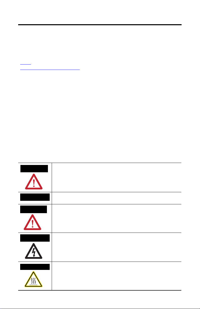
Throughout this manual, when necessary, we use notes to make you aware of safety considerations.
) describes some important differences between solid state
WARNING
IMPORTANT
ATTENTION
SHOCK HAZARD
BURN HAZARD
Identifies information about practices or circumstances that can cause an explosion in
a hazardous environment, which may lead to personal injury or death, property
damage, or economic loss.
Identifies information that is critical for successful application and understanding of
the product.
Identifies information about practices or circumstances that can lead to personal injury
or death, property damage, or economic loss. Attentions help you identify a hazard,
avoid a hazard and recognize the consequences.
Labels may be on or inside the equipment, for example, a drive or motor, to alert
people that dangerous voltage may be present.
Labels may be on or inside the equipment, for example, a drive or motor, to alert
people that surfaces may reach dangerous temperatures.
Publication 1752-IN001C-EN-P - January 2009
Page 3
SmartGuard 600 Controllers 3
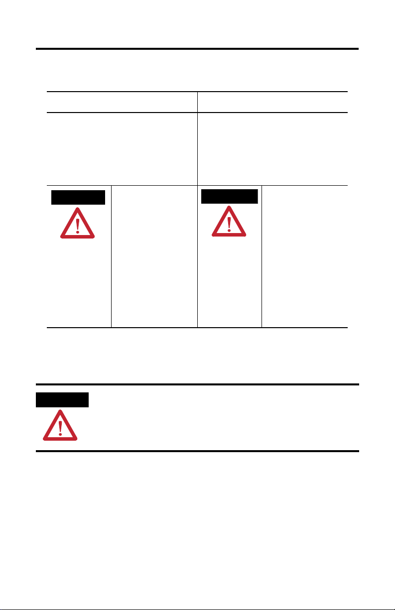
North American Hazardous Location Approval
The following information applies when operating
this equipment in hazardous locations.
Products marked "CL I, DIV 2, GP A, B, C, D" are suitable for use in
Class I Division 2 Groups A, B, C, D, Hazardous Locations an d
nonhazardous locations only. Each product is su pplied with
markings on the rating nameplate indicatin g the hazardous
location temperature code. When combinin g products within a
system, the most adverse temperature code (lowest "T" number)
may be used to help determine the overa ll temperature code of
the system. Combinations of equipment in your system are subject
to investigation by the local Authorit y Having Jurisdiction at the
time of installation.
WARNING
EXPLOSION HAZARD -
• Do not disconnect equipment
unless power has been removed
or the area is known to be
nonhazardous.
• Do not disconnect connections to
this equipment unless power has
been removed or the area is
known to be nonhazardous.
Secure any external connections
that mate to this equipment by
using screws, sliding latches,
threaded connectors, or other
means provided with this product.
• Substitution of components may
impair suitability for Class I,
Division 2.
• If this product contains batteries,
they must only be changed in an
area known to be nonhazardous.
General Safety Information
Informations sur l’utilisation de cet équipement en
environnements dangereux.
Les produits marqués "CL I, DIV 2, GP A, B, C, D" ne conviennent
qu'à une utilisation en environnement s de Classe I Division 2
Groupes A, B, C, D dangereux et non dangereu x. Chaque produit
est livré avec des marquages sur sa plaque d'identification q ui
indiquent le code de température pour les en vironnements
dangereux. Lorsque plusieurs produits sont combi nés dans un
système, le code de température le plus défavorable (code de
température le plus faible) peut ê tre utilisé pour déterminer le
code de température global du système. Les combinaisons
d'équipements dans le système sont sujettes à inspection par les
autorités locales qualifiées au moment de l'installation .
AVERTISSEMENT
RISQUE D’EXPLOSION –
• Couper le courant ou s'assurer
que l'environnement est classé
non dangereux avant de
débrancher l'équipement.
• Couper le courant ou s'assurer
que l'environnement est classé
non dangereux avant de
débrancher les connecteurs. Fixer
tous les connecteurs externes
reliés à cet équipement à l'aide
de vis, loquets coulissants,
connecteurs filetés ou autres
moyens fournis avec ce produit.
• La substitution de composants
peut rendre cet équipement
inadapté à une utilisation en
environnement de Classe I,
Division 2.
• S'assurer que l'environne ment est
classé non dangereux avant de
changer les piles.
ATTENTION
Safety Programmable Electronic Systems (PES)
Personnel responsible for the application of safety-related programmable electronic
systems (PES) shall be aware of the safety requirements in the application of the system
and shall be trained in using the system.
Publication 1752-IN001C-EN-P - January 2009
Page 4
4 SmartGuard 600 Controllers
ATTENTION
ATTENTION
Environment and Enclosure
This equipment is intended for use in Pollution Degree 2 Industrial environment, in
Overvoltage Category II applications (as defined in IEC publication 60664-1), at altitudes
up to 2000 m (6562 ft) without derating.
This equipment is considered Group 1, Class A industrial equipment according to
IEC/CISPR Publication 11. Without appropriate precautions, there may be potential
difficulties ensuring electromagnetic compatibility in other environments due to
conducted as well as radiated disturbance.
This equipment is supplied as open type equipment. It must be mounted within an
enclosure that is suitably designed for those specific environmental conditions that will
be present and appropriately designed to prevent personal injury resulting from
accessibility to live parts. The enclosure must have suitable flame-retardant properties to
prevent or minimize the spread of flame, complying with flame spread rating or 5VA, V2,
V1, V0 (or equivalent) if non-metallic. The interior of the enclosure must be accessible
only by the use of a tool. Subsequent sections of this publication may contain additional
information regarding specific enclosure type ratings that are required to comply with
certain product safety certifications.
In addition to this publication, see:
• Industrial Automation Wiring and Grounding Guidelines, Allen-Bradley publication
• NEMA Standards publication 250 and IEC publication 60529, as applicable, for
Prevent Electrostatic Discharge
This equipment is sensitive to electrostatic discharge, which can cause internal damage
and affect normal operation. Follow these guidelines when you handle this equipment:
• Touch a grounded object to discharge potential static.
.
1770-4.1
explanations of the degrees of protection provided by different types of enclosure.
• Wear an approved wrist grounding strap.
• Do not touch connectors or pins on component boards.
• Do not touch circuit components inside the equipment.
• Use a static-safe workstation, if available.
• Store the equipment in appropriate static-safe packaging when not in use.
Publication 1752-IN001C-EN-P - January 2009
Page 5

SmartGuard 600 Controllers 5
ATTENTION
T
ATTENTION
Protective Debris Strip
Do not remove the protective debris strip until after the controller and all the other
equipment near the controller is mounted and wiring is complete.
Once wiring is complete, remove the protective debris strip. Failure to remove the strip
before operating can cause overheating.
Serious injury may occur due to the loss of required safety function.
• Do not use test outputs as safety outputs.
• Do not use DeviceNet standard I/O data or explicit message data as safety data.
• Do not use the safety indicators for safety operations.
• Do not connect loads beyond the rated value to safety outputs or test outputs.
• Wire the controller properly so that the 24V DC line does not accidentally touch the
outputs.
• Ground the 0V line of the power supply for external output devices so that the
devices do not turn on when the safety output line or test output line is grounded.
• Do not dismantle, repair, or modify the controller. Doing so may impair the safety
functions.
About the SmartGuard 600 Controller
SmartGuard 600 controllers, catalog numbers 1752-L24BBB and 1752-L24BBBE, are
programmable electronic systems featuring 16 digital inputs, 8 digital outputs, 4 test
pulse sources, and connections for USB and DeviceNet safety communication. In
addition, the 1752-L24BBBE controller offers EtherNet/IP connectivity.
SmartGuard 600 controllers are certified for use in safety applications up to and
including Safety Integrity Level (SIL) 3, according to IEC 61508,
Performance Level PL(e) according to ISO 13849-1, and Category (CAT) 4,
according to EN 954-1.
Publication 1752-IN001C-EN-P - January 2009
Page 6
6 SmartGuard 600 Controllers
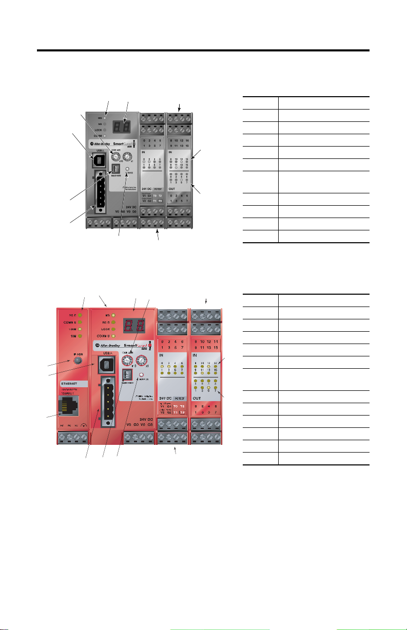
1752-L24BBB Controller
2
1
3
5
4
6
10
1752-L24BBBE Controller
1
10
5
11
46
27
12
7
8
9
Number Feature
1 Module status indicators
2 Alphanumeric display
3 Node address switches
4 Baud rate switches
5 USB port
6 DeviceNet communication
connector
7 Terminal connectors
8 Input status indicators
9 Output status indicators
10 Service switch
7
3
7
Number Feature
1 Module status indicators
2 Alphanumeric display
3 Node address switches
4 Baud rate switches
8
5 USB port
6 DeviceNet communication
connector
7 Terminal connectors
9
8 Input status indicators
9 Output status indicators
10 IP address display switch
11 Ethernet connector
12 Service switch
Publication 1752-IN001C-EN-P - January 2009
Page 7

SmartGuard 600 Controllers 7
Before You Begin
Before you install the controller, set its DeviceNet node address and communication
rate.
IMPORTANT
Turn off power to the controller before setting the node address or communication rate
via the switches.
Do not change the switch settings while the power supply is on. The controller will detect
this as a change in the configuration and will switch to the ABORT mode.
Set the Node Address
Use a small screwdriver to set the DeviceNet node address by using the two rotary
switches on the front panel of the controller. Use care not to scratch the switches.
Values from 00…63 are valid. The default setting is 63.
Follow these steps to set the node address.
1. Set the tens digit of the node address (decimal) by turning the left rotary
switch.
2. Set the ones digit by turning the right rotary switch.
3. To set the node address by using RSNetWorx for DeviceNet software, set the
rotary switches to a value from 64…99.
IMPORTANT
A node address duplication error will occur if the same node address is set for more than
one node.
Setting the Communication Rate
The default communication rate for a DeviceNet network is 125 Kbps.
If you choose to use a different communication rate, the length of the trunkline and
types of cable determine which communication rates your application can support.
DeviceNet Communication Rates and Cable Lengths
Communication
Rate
125 Kbps 420 m (1378 ft) 500 m (1640 ft) 100 m (328 ft) 156 m (512 ft)
250 Kbps 200 m (656 ft) 250 m (820 ft) 100 m (328 ft) 78 m (256 ft)
500 Kbps 75 m (246 ft) 100 m (328 ft) 100 m (328 ft) 39 m (128 ft)
Distance, Max Cumulative Drop
Flat Cable Thick Cable Thin Cable
Line Length
Publication 1752-IN001C-EN-P - January 2009
Page 8
8 SmartGuard 600 Controllers
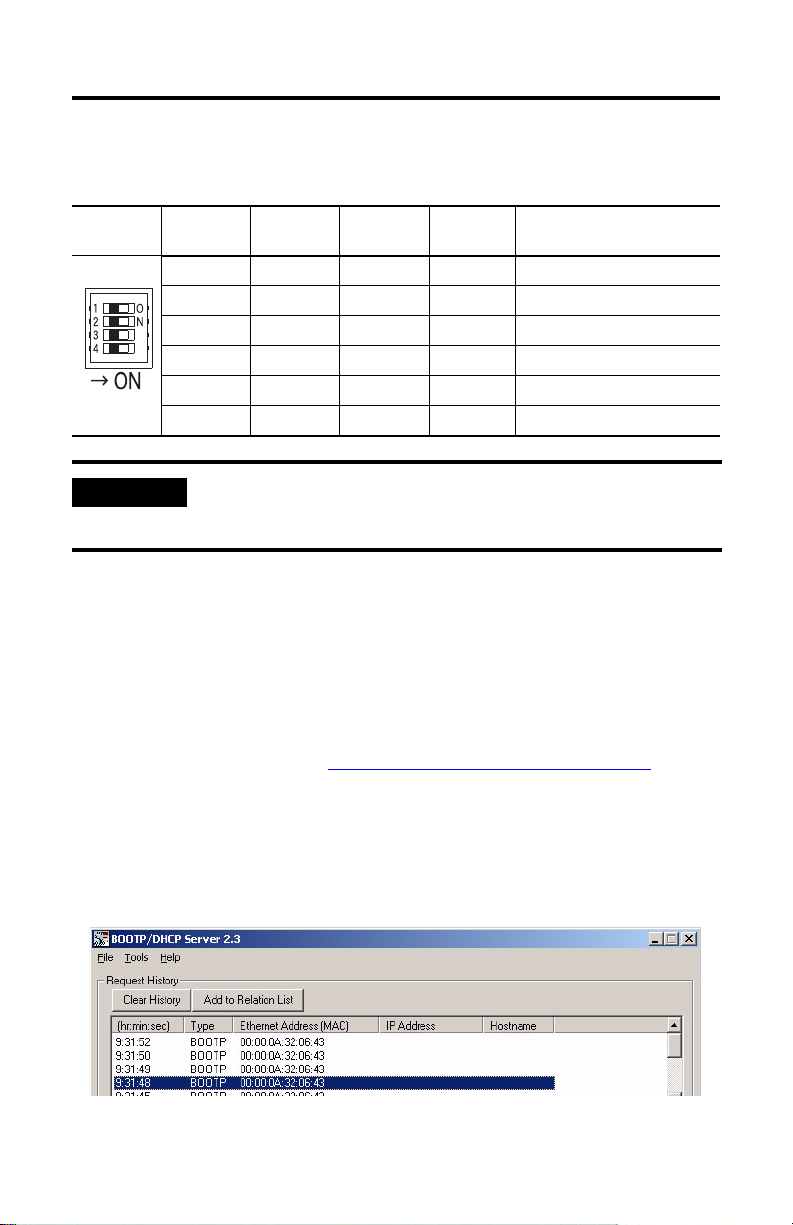
Set the communication rate by using the DIP switch on the front of the controller.
DIP Switch Settings
DIP Switch
Pin
IMPORTANT
1 2 3 4 Communication Rate
OFF OFF OFF OFF 125 Kbps
ON OFF OFF OFF 250 Kbps
OFF ON OFF OFF 500 Kbps
ON ON OFF OFF Set by software
ON or OFF ON or OFF ON OFF Set by software
ON or OFF ON or OFF ON or OFF ON Automatic baud-rate detection
If you change the communication rate of your network, make sure that all devices change
to the new communication rate. Mixed communication rates produce communication
errors.
Set the IP Address for Ethernet Communication
Connect the 1752-L24BBBE controller to the network via a 100 Mbps Ethernet
switch, which will help reduce collisions and lost packets, and increase bandwidth.
The 1752-L24BBBE controller is shipped with BOOTP enabled for setting the IP
address. You can use any commercially available BOOTP server. If you do not have
BOOTP Server capabilities on your network, download the free Rockwell
Automation BOOTP server from http://www.ab.com/networks/bootp.html
To set the IP address by using the Rockwell Automation BOOTP utility, follow
these steps.
.
1. Run the BOOTP utility.
2. Double-click the hardware address of the device you want to configure.
Publication 1752-IN001C-EN-P - January 2009
Page 9
SmartGuard 600 Controllers 9
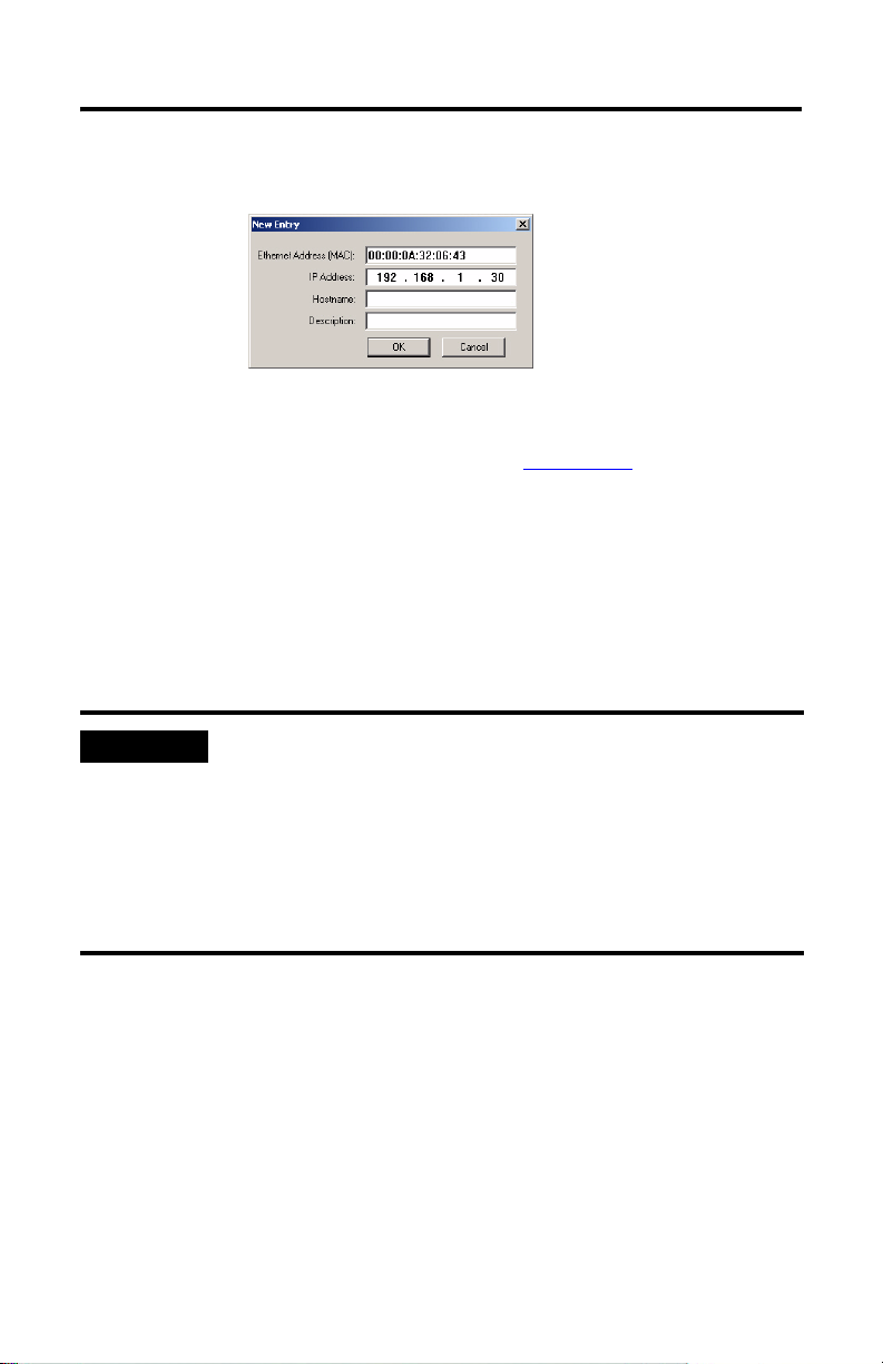
3. In the the New Entry pop-up dialog box, type the IP address you want to
assign to the device, and click OK.
The controller appears in the Relation List.
For detailed information on EtherNet/IP communication, refer to the EtherNet/IP
Performance and Application Solution, publication ENET-AP001.
Install the SmartGuard 600 Controller
To install the SmartGuard 600 controller, you must mount it on the DIN rail, wire
the terminals, and make communication connections.
Mount the SmartGuard 600 Controller
IMPORTANT
For effective cooling:
• mount the controller on a horizontal DIN rail. Do not mount the controller vertically.
• provide a gap of at least 50 mm (2.0 in.) above and below the controller and 5 mm
(0.20 in.) on each side.
• select a location where air flows freely or use an additional fan.
• do not mount the controller over a heating device.
Publication 1752-IN001C-EN-P - January 2009
Page 10

10 SmartGuard 600 Controllers
Mount the controller only to a DIN rail. Follow these steps to mount the controller
to an EN 50022-35x7.5 or EN 50022-35x15 DIN rail.
1. Hook the top slot over the DIN rail.
2. Snap the bottom of the controller into position while pressing the controller
down against the top of the rail.
Top Slot
DIN Rail
Latch
3. Attach end plates to each end of the DIN rail.
To remove the controller from the DIN rail, use a screwdriver to pull down the
latch and lift the controller off of the rail. The 1752-L24BBB controller has one latch
and the 1752-L24BBBE controller has two latches on the bottom of the controller.
Grounding the SmartGuard 600 Controller
ATTENTION
You must provide an acceptable grounding path for each device in your
application. Functionally ground the controller through its V0/G0 power
connection.
In addition, if you are using the 1752-L24BBBE controller, you should connect the
Ethernet ground terminal to an acceptable ground.
Publication 1752-IN001C-EN-P - January 2009
This product is grounded through the DIN rail to chassis ground. Use zinc plated
yellow-chromate steel DIN rail to assure proper grounding. The use of other DIN rail
materials (for example, aluminum or plastic) that can corrode, oxidize, or are poor
conductors, can result in improper or intermittent grounding. Secure DIN rail to mounting
surface approximately every 200 mm (7.8 in.) and use end anchors appropriately.
Page 11

SmartGuard 600 Controllers 11
Ethernet Ground
Refer to the Industrial Automation Wiring and Grounding Guidelines, publication
1770-4.1, for additional information.
Connecting a Power Supply
Power for the controller is provided via an external 24V DC power source. The
output hold time must be 20 ms or longer.
To comply with the CE Low Voltage Directive (LVD), DeviceNet connections and
I/O must be powered by a DC source compliant with safety extra low voltage
(SELV) or protected extra low voltage (PELV).
To comply with UL restrictions, DeviceNet connections and I/O must be powered
by DC sources whose secondary circuits are isolated from the primary circuit by
double insulation or reinforced insulation. The DC power supply must satisfy the
requirements for Class 2 circuits or limited voltage/current circuits defined in
UL 508.
TIP
R
The following Rockwell Automation 1606 power supplies are Class 2, SELV- and
PELV-compliant, and they meet the isolation and output hold-off time requirements of the
SmartGuard 600 controller:
•1606-XLP30E
•1606-XLP50E
•1606-XLP50EZ
• 1606-XLP72E
• 1606-XLP95E
• 1606-XLDNET4
• 1606-XL60DR
• 1606-XLSDNET4
The SmartGuard controller has three V/G terminal pairs that require a power
connection. There are two V0/G0 pairs, but because they are internally connected,
you need to only connect one V0/G0 pair. You can use the other pair to distribute
power to other devices.
Publication 1752-IN001C-EN-P - January 2009
Page 12

12 SmartGuard 600 Controllers
Power Supply Connections
+-
+-
+-
Wiring the SmartGuard 600 Controller
See page 24 for appropriate wire size and torque specifications.
Controller Terminal Descriptions
Terminal Designation Description
V0 Power terminal for internal circuit (logic).
G0 Power terminal for internal circuit (logic).
V1 Power terminal for input circuits and test outputs.
G1 Power terminal for input circuits and test outputs.
V2 Power terminal for safety outputs.
G2 Power terminal for safety outputs.
IN0…IN15 Terminals for safety inputs.
T0…T3 These are test output terminals that can provide pulse test sources for safety
inputs IN0...IN15. T3 can also support wire off detection and burned out bulb
detection for a load such as a muting lamp.
OUT0…OUT7 Terminals for safety outputs.
WARNING
If you connect or disconnect wiring while the field-side power is applied, an electrical arc
can occur. This could cause an explosion in hazardous location installations. Be sure that
power is removed or the area is nonhazardous before proceeding.
Publication 1752-IN001C-EN-P - January 2009
Page 13

SmartGuard 600 Controllers 13
WARNING
IMPORTANT
If you connect or disconnect the removable terminal block (RTB) while the field-side
power is applied, an electrical arc can occur. This could cause an explosion in hazardous
location installations. Be sure that power is removed or the area is nonhazardous before
proceeding.
Prepare stranded wires by attaching ferrules with plastic insulation covers (compliant
with the DIN 46228-4 standard). Ferrules similar in appearance but not compliant may not
match the terminal block on the controller.
Wiring Input Devices
ATTENTION
Input devices with mechanical contact outputs, such as emergency stop buttons
and safety limit switches, use both a safety input terminal and a test output
terminal. This enables the circuit to reach a Category 4 rating.
When safety devices are connected via test outputs to an input circuit on the
SmartGuard controller, we recommend the length of the wire to be 30 m (98.4 ft) or
less.
Applying an inappropriate DC or any AC voltage may result in a loss of safety function,
product damage, or serious injury. Properly apply only the specified voltage to controller
inputs.
Input Devices with Mechanical Contact Outputs
V1
4.5 mA Typical
Tx
SmartGuard 600
Controller
INx
24V DC
G1
Publication 1752-IN001C-EN-P - January 2009
Page 14

14 SmartGuard 600 Controllers
Devices, such as light curtains, with current-sourcing PNP semiconductor outputs
send a signal to the SmartGuard 600 controller safety-input terminal and do not use
a test output.
Input Devices with PNP Semiconductor Outputs
4.5 mA Typical
V1
24V DC
Tx
Wiring Output Devices
ATTENTION
Serious injury may occur due to a loss of required safety functions.
Do not connect loads beyond the rated value of safety or test outputs.
Do not use test outputs as safety outputs.
Wire the controller properly so that the 24V DC lines do not touch the safety or test
outputs.
Do not apply the power supply to the test output terminals.
Ground the 0V line of the power supply for external output devices so that the devices do
not turn on when the safety output line or the test output line is grounded.
Separate I/O cables from high voltage or high current lines.
OSSDx
24V DC
GND
INx
G1
SmartGuard 600
Controller
Publication 1752-IN001C-EN-P - January 2009
Page 15

Output Device Wiring
SmartGuard 600 Controllers 15
SmartGuard
600 Controller
V2
OUTx
24V DC
0.5 A Max
Load
G2
Making Communication Connections
WARNING
You can configure the network and controller on the DeviceNet network by using a
1784-PCD card inside your personal computer and RSNetWorx for DeviceNet
software. You can also configure the network and controller by using the
controller’s USB port and RSNetWorx for DeviceNet software.
In addition, you can communicate via the EtherNet/IP network. The EtherNet/IP
address and subnet mask are configured with the RSLinx module configuration. The
1752-L24BBBE controller is shipped with BOOTP enabled for setting the
IP Address. See page 8
Do not connect or disconnect the communication cable with power applied to this
controller or any device on the network, because an electrical arc can occur. This could
cause an explosion in hazardous location installations. Be sure that power is removed or
the area is nonhazardous before proceeding.
for details.
Publication 1752-IN001C-EN-P - January 2009
Page 16

16 SmartGuard 600 Controllers
Connect to the DeviceNet Port
Follow these steps to connect to the DeviceNet port.
1. Wire the connector according to the colors on the connector.
Wire No. Wire Color Connects to
1Red V+
2WhiteCAN H
3— Drain
4Blue CAN L
5BlackV-
D
D
D
D
D
2. Attach the connector to the DeviceNet port.
3. Tighten the screws to 0.25…0.3 N•m (2.21…2.65 lb•in).
For detailed DeviceNet connection information, refer to the DeviceNet Media
Design Installation Guide, publication DNET-UM072
. Also refer to the Industrial
Automation Wiring and Grounding Guidelines, publication 1770-4.1.
1
2
3
4
5
Connecting to the USB Port
Connect the USB communication connector to your personal computer when you
want to configure the network and controller by using RSNetWorx for DeviceNet
software. Use a commercially available USB-A to USB-B male/male cable to make
the connection.
ATTENTION
WARNING
Publication 1752-IN001C-EN-P - January 2009
The USB cable length must be less than 3 m (10 ft).
The USB port is intended for temporary programming purposes only and is not intended for
permanent connection.
If you connect or disconnect the USB cable with power applied to this module or any
device on the USB network, an electrical arc could occur. This could cause an explosion in
hazardous location installations. Be sure that power is removed or the area is
nonhazardous before proceeding.
Page 17

SmartGuard 600 Controllers 17
Connecting to the Ethernet Port
Use an RJ45 connector to connect the controller to the EtherNet/IP network.
ATTENTION
WARNING
The cable length must be less then 100 m (328 ft) between hub and nodes.
If you connect or disconnect the Ethernet cable with power applied to this controller or any
other device on this network, an electrical arc can occur. This could cause an explosion in
hazardous location installations. Be sure that power is removed or the area is
nonhazardous before proceeding.
Ethernet Pin Placement
Pin No. Pin Name Pin Placement
8 Not used
7 Not used
6RD5 Not used
4 Not used
3RD+
2TD1TD+
8
1
Interpreting the Status Indicators
The SmartGuard 600 controller features status indicators for module, DeviceNet and
EtherNet/IP network status, lock, USB and EtherNet/IP communication, individual
input and output status, as well as an alphanumeric status display for DeviceNet
error codes, DeviceNet node address, and EtherNet/IP address information.
Publication 1752-IN001C-EN-P - January 2009
Page 18

18 SmartGuard 600 Controllers
Alphanumeric Status Display
The controller’s alphanumeric display provides information about the module’s
status. Under normal operating conditions, the display shows the node address of
the module, 00…63 in decimal format. If the controller is operating in a standalone
configuration (not networked), the display shows ‘nd’. The display flashes when
the controller is self-testing, configuring, or in Idle mode. If a fault exists, the
display alternates between the error code and the node address where the error
occurred. If a fatal error has occurred, the display shows the error code only.
When the service switch is pressed, the display shows the controller’s
safety-configuration signature two digits at a time. The configuration signature can
also be viewed on the Safety tab of the Controller Properties dialog box in
RSNetWorx for DeviceNet software. You can use the configuration signature to
verify that the program and configuration of the controller has not been changed.
When the IP address display switch is pressed for 1 second or longer, the display
shows the EtherNet/IP address that is set. The error code ‘n4’ is displayed if an error
occurs in the EtherNet/IP configuration.
Status Indicators
Use these tables to interpret the color and status combinations of the status
indicators and take recommended actions where applicable.
Module Status (MS) Indicator Descriptions
If the Module Status
(MS) indicator is
Off No power. Refer to the corrective action following this
Green, on The controller is operating in Run
Green, flashing The controller is idle.
Red, flashing A recoverable fault exists. Refer to the corrective action following this
Red, on An unrecoverable fault exists.
Red/green flashing Self-test in progress. Or, the
If your Module Status indicator is off, follow these steps.
1. Cycle the power supply.
2. Take corrective actions for noise.
Publication 1752-IN001C-EN-P - January 2009
It means Take this action
table.
No action required.
mode and under normal conditions.
table.
controller’s configuration is being
downloaded or is incomplete or
incorrect.
Page 19

SmartGuard 600 Controllers 19
3. Contact Rockwell Automation.
If your Module Status indicator is flashing red, follow these steps.
1. Configure the switches properly.
2. Reset the configuration data.
If your Module Status indicator is solid red (on), follow these steps.
1. Cycle the power supply.
2. Check external wiring.
3. Take corrective actions for noise.
4. Contact Rockwell Automation.
If your Module Staus indicator is flashing red and green, follow these steps.
1. Configure the switches properly.
2. Set the safety network number.
3. Reconfigure the device.
DeviceNet Network Status (NS D) Indicator Descriptions
If the DeviceNet
Network Status
(NS D) indicator is
Off The controller is not online or may not
Green, on The controller is online; connections
Green, flashing The controller is online; no
Red, on Communication failure due to
Red, flashing Communication timeout.
Red/green flashing The Safety Network Number (SNN) is
It means Take this action
Refer to the corrective action following this
have power from the DeviceNet
network.
are established.
connections are established.
duplicate MAC ID (error code F0) or
Bus OFF (error code F1).
being set.
table.
No action required.
Refer to the corrective action following this
table
No action required.
Publication 1752-IN001C-EN-P - January 2009
Page 20

20 SmartGuard 600 Controllers
If your Network Status indicator is off, follow these steps.
1. Cycle the power supply.
2. Check external wiring.
3. Take corrective actions for noise.
4. Contact Rockwell Automation.
If your Network Status indicator is on or flashing red, follow these steps.
1. View the Alphanumeric display for the node address of the error and error
code.
2. Check that node addresses have not been duplicated.
3. Make sure the communication rate is the same for all nodes.
4. Check that cables are not loose, disconnected or too long.
5. Verify that terminating resistors have been installed only at both ends of the
main line.
6. Take corrective action for noise.
7. Make sure target devices are configured, verified, and in normal operating
state.
Lock Configuration (Lock) Status Indicator Descriptions
If the Lock
Configuration (Lock)
status indicator is
Yellow, on A locked valid configuration exists. No action required.
Yellow, flashing An unlocked valid configuration exists. Lock the configuration before operating the
Off The configuration is invalid. Reconfigure the controller.
Publication 1752-IN001C-EN-P - January 2009
It means Take this action
safety system.
Page 21

SmartGuard 600 Controllers 21
USB Communication (COMM U) Status Indicator Descriptions
If the USB
Communication
(COMM U) status
indicator is
Yellow, flashing The controller is communicating. No action required.
Off The controller is not communicating.
It means Take this action
I/O (inputs 0...15, outputs 0...7) Status Indicators Descriptions
If the I/O status
indicators are
Red, on A failure has been detected in the
Red, flashing A failure has been detected in the
Off The input or output signal is off.
Yellow, on The input or output signal is on. No action required.
It means Take this action
Refer to the corrective action following this
input or output circuit or a discrepancy
error has occurred in the I/O set for
Dual-channel mode.
associated I/O circuit’s dual channel
configuration.
table.
If your I/O Status indicator is on or flashing red, follow these steps.
1. Check that the signal wire:
• is not making contact with the power source (positive side).
• does not have an earth fault.
• is not disconnected.
2. Make sure there is not a short-circuit between signal wires.
3. Check that there is no overcurrent for the output.
4. Make sure there is no failure in the connected devices.
5. Verify that the Discrepancy Time settings are valid.
If your I/O Status indicator is off, follow these steps.
1. Check that the power supply voltage is set within the specified range.
2. Make sure a cable or wire is not disconnected.
Publication 1752-IN001C-EN-P - January 2009
Page 22

22 SmartGuard 600 Controllers
EtherNet/IP Network Status (NS E) Indicator Descriptions
If the EtherNet/IP
Network Status
(NS E) indicator is
Off The controller does not have an IP
Green, flashing The controller has no established
Green, on The controller has at least one
Red, flashing One or more of the connections in
Red, on The controller has detected that its IP
If your EtherNet/IP Status indicator is off, follow these steps.
1. Apply power to the controller.
It means Take this action
address or is not turned on.
connections but has obtained an IP
address.
established connection (even to the
message router).
which this device is the target has
timed out. This shall be left only if all
timed out connections are
reestablished or if the device is reset.
address is already in use.
Refer to the corrective action following this
table.
No action required.
Refer to the corrective action following this
table.
Reset the IP address.
2. Set the IP address.
If your EtherNet/IP Status indicator is flashing green, follow these steps.
1. Check the wiring to the controller.
2. Configure the originator to connect to the target.
If your EtherNet/IP Status indicator is flashing red, follow these steps.
1. Check external wiring.
2. Check the endpoints.
3. Check the switches.
Publication 1752-IN001C-EN-P - January 2009
Page 23

SmartGuard 600 Controllers 23
EtherNet/IP Communication (COMM E) Status Indicator Descriptions
If the EtherNet/IP
Communication
(COMM E) status
indicator is
Green, on The controller is communicating on
Off The controller is not communicating
It means Take this action
No action required.
the Ethernet network.
on the Ethernet network.
Ethernet Network Speed (100) Status Indicator Descriptions
If the Ethernet
Network Speed (100)
status indicator is
Yellow, on The communication rate is 100 Mbps. No action required.
(1)
Off
(1) If this indicator is Off along with the Network Speed (10) indicator, check your Ethernet connection.
It means Take this action
The communication rate is 10 Mbps. Check that the Network Speed (10) indicator
is on.
Ethernet Network Speed (10) Status Indicator Descriptions
If the Ethernet
Network Speed (10)
status indicator is
Yellow, on The communication rate is 10 Mbps. No action required.
(1)
Off
(1) If this indicator is Off along with the Network Speed (100) indicator, check your Ethernet connection.
Refer to the SmartGuard 600 Controller User Manual, publication 1752-UM001
more information on recovering from I/O errors.
ATTENTION
It means Take this action
The communication rate is 100 Mbps. Check that the Network Speed (100) indicator
is on.
Status indicators are not reliable indicators for safety functions. They should be used
only for general diagnostics during commissioning and troubleshooting. Do not use
status indicators as operational indicators.
Publication 1752-IN001C-EN-P - January 2009
, for
Page 24

24 SmartGuard 600 Controllers
Specifications
SmartGuard 600 Controllers - 1752-L24BBB, 1752-L24BBBE
Attribute 1752-L24BBB 1752-L24BBBE
Dimensions (HxWxD), approx.
(4)
x 99.4 x 131.4 mm
99.0
(4)
(3.90
x 3.91 x 5.18
Weight, approx. 460 g (1.23 lb) 575 g (1.54 lb)
DeviceNet current load, max 15 mA @ 24V DC
Supply voltage
(1)
20.4…26.4V DC (24V DC, -15…10%)
Inrush current - unit power supply 4.8 A peak for 600 μs @ V0/G0
Inrush current - safety input power
2.6 A peak for 3 ms @ V1/G1
supply
DeviceNet voltage range 11…25V DC
Current consumption
230 mA @ 24V DC 280 mA @ 24V DC
(V0 - internal logic circuit)
Overload protection Shut down of the affected output with cyclic reconnecting
Isolation voltage 50V, Functional insulation type
Tested at 600V AC for 60 s, between all groups
Wire type Copper
Wiring category
Wire size
(2)
2 - on power, signal, and
communication ports
For power supply and I/O, use 0.2…2.5 mm
or 0.34…1.5 mm
connecting, prepare standard wires by attaching ferrules with plastic
insulation collars (DIN 46228-4 standard compatible)
For Ethernet connections:
RJ45 connector according to IEC 60603-7, 2 or 4 pair Category 5e
minimum cable according to TIA 569-B.1 or Category 5 cable according
to ISO/IEC 24701
I/O terminal screw torque 0.56…0.79 N•m (5…7 lb•in)
North American temperature code T4A
Input type Current sinking
Voltage, on-state input, min 11V DC
Voltage, off-state input, max 5V DC
Current, off-state input, max 1 mA
Input current 4.5 mA
Input impedance 2.6 kΩ
(5)
(5)
in.)
(4)
99.0
x 113.0 x 131.4
(4)
(3.90
x 4.48 x 5.18
2 - on power, 1 - on signal, 1 communication ports
2
2
(16…22 AWG) standard flexible wire. Before
(12…24 AWG) solid wire,
(5)
mm
(5)
in.)
Publication 1752-IN001C-EN-P - January 2009
Page 25

SmartGuard 600 Controllers 25
SmartGuard 600 Controllers - 1752-L24BBB, 1752-L24BBBE
Attribute 1752-L24BBB 1752-L24BBBE
Test output type Current sourcing
Pulse test output current
(3)
Test output surge current 0.7 A
Pulse test off-state voltage, max 1.2V
Pulse test output leakage current,
max
Muting lamp output current (T3)
• More than 25 mA
• Less than 5 mA
Output type Current sourcing
Output current 0.5 A
Output surge current 0.5 A
Voltage, off-state output max 1.2V
Leakage current, off-state output,
max
Heat dissipation 9.3 W under max load
Ethernet Communication
CIP connections Not applicable 2
Auto negotiation Not applicable Supported
Data rate Not applicable 10/100 Mbps
Duplex Not applicable Full/half
Allowable unit
communication bandwidth
Explicit message
communication
(1) V0/G0 for internal logic circuit; V1/G1 for external input devices and test outputs; V2/G2 for external output devices.
(2) Use this Conductor Category information for planning conductor routing. Refer to Industrial Automation Wiring and
Grounding Guidelines, publication 1770-4.1
(3) T0...T3 total current at the same time: 1.4 A.
(4) Height includes terminal connectors.
(5) Depth includes DeviceNet connector.
(6) PPS is packets per second. It indicates the number of send or receive packets that can be processed per second.
(7) The maximum message length for class 3 connection and UCMM connection.
0.7 A
0.1 mA
• Normal operation (to avoid fault when used as a muting lamp
output)
• Fault (a fault indication is generated when used as a muting
lamp output)
0.1 mA
Not applicable
Not applicable
.
3000 pps
502 Bytes
(6)
(7)
Publication 1752-IN001C-EN-P - January 2009
Page 26

26 SmartGuard 600 Controllers
Environmental Specifications
Attribute 1752-L24BBB 1752-L24BBBE
Temperature, storage IEC 60068-2-1 (Test Ab, Unpackaged Nonoperating Cold),
IEC 60068-2-2 (Test Bb, Unpackaged Nonoperating Dry Heat),
IEC 60068-2-14 (Test Na, Unpackaged Nonoperating Thermal Shock):
-40…70 °C (-40…158 °F)
Temperature, operating IEC 60068-2-1 (Test Ad, Operating Cold),
IEC 60068-2-2 (Test Bd, Operating Dry Heat),
IEC 60068-2-14 (Test Nb, Operating Thermal Shock):
-10…55 °C (14…131 °F) (surrounding air temperature)
Relative humidity IEC 60068-2-30
(Test Db, Unpackaged Nonoperating Damp Heat):
10…95% noncondensing
Vibration IEC 60068-2-6 (Test Fc, Operating):
0.35 mm @ 10…57 Hz
5 g @ 57…150 Hz
Shock, operating IEC 60068-2-27 (Test Ea, Unpackaged Shock): 15 g
Shock, nonoperating IEC 60068-2-27 (Test Ea, Unpackaged Shock): 30 g
Enclosure type rating Meets IP20
Emissions CISPR 11: Group 1, Class A
ESD immunity IEC 61000-4-2:
• 4 kV contact discharges
• 8 kV air discharges
Radiated RF immunity IEC 61000-4-3:
• 10 V/m with 1 kHz
sine-wave 80% AM from
80…1000 MHz
• 10 V/m with 1 kHz
sine-wave 80% AM from
1.4…2.0 GHz
• 10 V/m with 200 Hz 50%
Pulse 100% AM at 900 MHz
• 10 V/m with 200 Hz 50%
Pulse 100% AM at 1200
MHz
• 3 V/m with 1 kHz sine-wave
80% AM from 2000…2700
MHz
IEC 60068-2-6 (Test Fc, Operating):
5 g @ 10…500 Hz
IEC 61000-4-2:
• 6 kV contact discharges
• 8 kV air discharges
IEC 61000-4-3:
• 10 V/m with 1 kHz
sine-wave 80% AM from
80…1000 MHz
• 10 V/m with 1 kHz
sine-wave 80% AM from
1.4…2.0 GHz
• 20 V/m with 200 Hz 50%
Pulse 100% AM at 800, 900,
1200 MHz
• 3 V/m with 1 kHz sine-wave
80% AM from 2000…2700
MHz
Publication 1752-IN001C-EN-P - January 2009
Page 27

SmartGuard 600 Controllers 27
Environmental Specifications
Attribute 1752-L24BBB 1752-L24BBBE
EFT/B immunity IEC 61000-4-4:
• ±2 kV @ 5 kHz on power
ports
• ±2 kV @ 5 kHz on signal
ports
• ±2 kV @ 5 kHz on
communication ports
Surge transient immunity IEC 61000-4-5:
• ±1 kV line-line (DM) and ±2
kV line-earth (CM) on power
ports
• ±1 kV line-line (DM) and ±2
kV line-earth (CM) on signal
ports
• ±1 kV line-earth (CM) on
communication ports
Conducted RF immunity IEC 61000-4-6:
• 10V rms with 1 kHz sine-wave 80% AM from 150 kHz…80 MHz
IEC 61000-4-4:
• ±2 kV @ 5 kHz on power
ports
• ±1 kV @ 5 kHz on signal
ports
• ±1 kV @ 5 kHz on
communication ports
IEC 61000-4-5:
• ±500V line-line (DM) and ±1
kV line-earth (CM) on power
ports
• ±1 kV line-earth (CM) on
signal ports
• ±1 kV line-earth (CM) on
communication ports
Certifications
Certification
(when product is marked)
c-UL-us UL Listed for Class I, Division 2 Group A,B,C,D Hazardous Locations, certified
CE European Union 2004/108/EEC EMC Directive, compliant with:
C-Tick Australian Radiocommunications Act, compliant with:
TÜV TÜV Certified for Functional Safety
UL UL Certified for Functional Safety. See UL File E256621.
(1)
Valu e
for US and Canada. See UL File E194810.
• EN 61000-6-4; Industrial Emissions
• EN 61131-2; Programmable Controllers (Clause 8, Zone A & B)
• EN 61326-1; Meas./Control/Lab., Industrial Requirements
• EN 61000-6-2; Industrial Immunity
AS/NZS CISPR 11; Industrial Emissions
Functional Safety: SIL 1 to 3, according to IEC 61508; Performance Level PL(e)
according to ISO 13849-1, Category 1 to 4, according to EN954-1; NFPA79;
when used as described in the SmartGuard Controllers Safety Reference
Manual, publication 1752-RM001
.
Publication 1752-IN001C-EN-P - January 2009
Page 28

(1) See the Product Certification link at http://ab.com for Declarations of Conformity, Certificates, and other certifications
details.
Additional Resources
These documents contain additional information concerning related Rockwell
Automation products.
Resource Description
SmartGuard 600 User Manual, publication
1752-UM001
SmartGuard 600 Safety Reference Manual,
publication 1752-RM001
Industrial Automation Wiring and Grounding
Guidelines, publication 1770-4.1
Product Certifications website,
http://ab.com
You can view or download publications at
http://literature.rockwellautomation.com
documentation, contact your local Rockwell Automation distributor or sales
representative.
Information on wiring, configuring, operating, and
troubleshooting a SmartGuard 600 controller.
Information on the safety concept of the SmartGuard 600
controller, as well as PFD and PFH values and reaction time
calculations.
Provides general guidelines for installing a Rockwell
Automation industrial system.
Provides declarations of conformity, certificates, and other
certification details.
. To order paper copies of technical
Allen-Bradley, Rockwell Automation, SmartGuard, RSNetWorx for DeviceNet, and RSLinx are trademarks of Rockwell
Automation, Inc.
Trademarks not belonging to Rockwell Automation are property of their respective companies.
Publication 1752-IN001C-EN-P - January 2009 PN 28964
Supersedes Publication 1752-IN001B-EN-P - October 2006 Copyright © 2009 Rockwell Automation, Inc. All rights reserved. Printed in Japan.
 Loading...