

Page 1

User Manual
SmartGuard 600 Controllers
Catalog Numbers 1752-L24BBB, 1752-L24BBBE
Page 2
Important User Information
IMPORTANT
Read this document and the documents listed in the additional resources section about installation, configuration, and
operation of this equipment before you install, configure, operate, or maintain this product. Users are required to
familiarize themselves with installation and wiring instructions in addition to requirements of all applicable codes, laws,
and standards.
Activities including installation, adjustments, putting into service, use, assembly, disassembly, and maintenance are required
to be carried out by suitably trained personnel in accordance with applicable code of practice.
If this equipment is used in a manner not specified by the manufacturer, the protection provided by the equipment may be
impaired.
In no event will Rockwell Automation, Inc. be responsible or liable for indirect or consequential damages resulting from the
use or application of this equipment.
The examples and diagrams in this manual are included solely for illustrative purposes. Because of the many variables and
requirements associated with any particular installation, Rockwell Automation, Inc. cannot assume responsibility or
liability for actual use based on the examples and diagrams.
No patent liability is assumed by Rockwell Automation, Inc. with respect to use of information, circuits, equipment, or
software described in this manual.
Reproduction of the contents of this manual, in whole or in part, without written permission of Rockwell Automation,
Inc., is prohibited.
Throughout this manual, when necessary, we use notes to make you aware of safety considerations.
WARNING: Identifies information about practices or circumstances that can cause an explosion in a hazardous environment,
which may lead to personal injury or death, property damage, or economic loss.
ATTENTION: Identifies information about practices or circumstances that can lead to personal injury or death, property
damage, or economic loss. Attentions help you identify a hazard, avoid a hazard, and recognize the consequence.
Identifies information that is critical for successful application and understanding of the product.
Labels may also be on or inside the equipment to provide specific precautions.
SHOCK HAZARD: Labels may be on or inside the equipment, for example, a drive or motor, to alert people that dangerous
voltage may be present.
BURN HAZARD: Labels may be on or inside the equipment, for example, a drive or motor, to alert people that surfaces may
reach dangerous temperatures.
ARC FLASH HAZARD: Labels may be on or inside the equipment, for example, a motor control center, to alert people to
potential Arc Flash. Arc Flash will cause severe injury or death. Wear proper Personal Protective Equipment (PPE). Follow ALL
Regulatory requirements for safe work practices and for Personal Protective Equipment (PPE).
Allen-Bradley, CompactLogix, ControlLogix, FactoryTalk, Guard I/O, GuardLogix, MicroLogix, PanelBuilder, PanelView Plus, PLC-5, POINT I/O, Rockwell Software, RSLinx, R SLogix 5000, RSNetWorx, RSView, SLC
and SmartGuard are trademarks of Rockwell Automation, Inc.
EtherNet/IP and DeviceNet are trademarks of the ODVA
Trademarks not belonging to Rockwell Automation are property of their respective companies.
Page 3

Summary of Changes
The information below summarizes the changes to this manual since the last
printing.
To help you find new and updated information in this release of the manual, we
have included change bars as shown to the right of this paragraph.
Top ic Pag e
Updated the procedure for handling forgotten passwords 48
Updated DeviceNet driver information 50
Rockwell Automation Publication 1752-UM001E-EN-P - June 2014 3
Page 4

Summary of Changes
Notes:
4 Rockwell Automation Publication 1752-UM001E-EN-P - June 2014
Page 5

Summary of Changes
Table of Contents
Preface
Overview
Table of Contents
Important User Information . . . . . . . . . . . . . . . . . . . . . . . . . . . . . . . . . . . . . . . . 2
Who Should Use This Manual . . . . . . . . . . . . . . . . . . . . . . . . . . . . . . . . . . . . 13
Purpose of This Manual . . . . . . . . . . . . . . . . . . . . . . . . . . . . . . . . . . . . . . . . . . 13
Additional Resources . . . . . . . . . . . . . . . . . . . . . . . . . . . . . . . . . . . . . . . . . . . . . 13
Common Techniques Used in This Manual . . . . . . . . . . . . . . . . . . . . . . . . 14
Chapter 1
Introduction. . . . . . . . . . . . . . . . . . . . . . . . . . . . . . . . . . . . . . . . . . . . . . . . . . . . . 15
About the SmartGuard 600 Controller . . . . . . . . . . . . . . . . . . . . . . . . . . . . 15
Hardware. . . . . . . . . . . . . . . . . . . . . . . . . . . . . . . . . . . . . . . . . . . . . . . . . . . . 17
Communication . . . . . . . . . . . . . . . . . . . . . . . . . . . . . . . . . . . . . . . . . . . . . 20
Configuration and Programming . . . . . . . . . . . . . . . . . . . . . . . . . . . . . . 20
Status and Error Monitoring . . . . . . . . . . . . . . . . . . . . . . . . . . . . . . . . . . 20
Safety Concept of the Controller . . . . . . . . . . . . . . . . . . . . . . . . . . . . . . . . . . 21
Additional Resource. . . . . . . . . . . . . . . . . . . . . . . . . . . . . . . . . . . . . . . . . . . . . . 21
Installing and Wiring the SmartGuard
600 Controller
Chapter 2
Introduction. . . . . . . . . . . . . . . . . . . . . . . . . . . . . . . . . . . . . . . . . . . . . . . . . . . . . 23
General Safety Information . . . . . . . . . . . . . . . . . . . . . . . . . . . . . . . . . . . . . . . 23
Understanding Node Addressing . . . . . . . . . . . . . . . . . . . . . . . . . . . . . . . . . . 25
Set the Node Address. . . . . . . . . . . . . . . . . . . . . . . . . . . . . . . . . . . . . . . . . . . . . 26
Setting the Communication Rate. . . . . . . . . . . . . . . . . . . . . . . . . . . . . . . . . . 26
DeviceNet Communication . . . . . . . . . . . . . . . . . . . . . . . . . . . . . . . . . . . 26
Ethernet Communication. . . . . . . . . . . . . . . . . . . . . . . . . . . . . . . . . . . . . 28
Mount the SmartGuard Controller . . . . . . . . . . . . . . . . . . . . . . . . . . . . . . . . 29
Grounding the SmartGuard Controller . . . . . . . . . . . . . . . . . . . . . . . . . . . . 30
Connecting a Power Supply. . . . . . . . . . . . . . . . . . . . . . . . . . . . . . . . . . . . . . . 30
Making Communication Connections. . . . . . . . . . . . . . . . . . . . . . . . . . . . . 31
Connect to the DeviceNet port. . . . . . . . . . . . . . . . . . . . . . . . . . . . . . . . 31
Connecting to USB Port. . . . . . . . . . . . . . . . . . . . . . . . . . . . . . . . . . . . . . 33
Connecting to the Ethernet port. . . . . . . . . . . . . . . . . . . . . . . . . . . . . . . 33
Wiring the SmartGuard 600 Controller. . . . . . . . . . . . . . . . . . . . . . . . . . . . 34
Wire Output Devices . . . . . . . . . . . . . . . . . . . . . . . . . . . . . . . . . . . . . . . . . 36
Wiring Examples . . . . . . . . . . . . . . . . . . . . . . . . . . . . . . . . . . . . . . . . . . . . . 37
Chapter 3
Set Up Your DeviceNet Network
Introduction. . . . . . . . . . . . . . . . . . . . . . . . . . . . . . . . . . . . . . . . . . . . . . . . . . . . . 41
Connecting a Computer to the DeviceNet Network . . . . . . . . . . . . . . . . 41
Configure a Driver for the Network. . . . . . . . . . . . . . . . . . . . . . . . . . . . 41
Make Sure the Driver Works . . . . . . . . . . . . . . . . . . . . . . . . . . . . . . . . . . 42
Commission All Nodes . . . . . . . . . . . . . . . . . . . . . . . . . . . . . . . . . . . . . . . . . . . 42
Browse the Network. . . . . . . . . . . . . . . . . . . . . . . . . . . . . . . . . . . . . . . . . . . . . . 44
Rockwell Automation Publication 1752-UM001E-EN-P - June 2014 5
Page 6

Table of Contents
Configuration Signature . . . . . . . . . . . . . . . . . . . . . . . . . . . . . . . . . . . . . . . . . . 44
Safety Reset (optional) . . . . . . . . . . . . . . . . . . . . . . . . . . . . . . . . . . . . . . . . . . . . 45
Setting Passwords (optional) . . . . . . . . . . . . . . . . . . . . . . . . . . . . . . . . . . . . . . 47
Set or Change a Password . . . . . . . . . . . . . . . . . . . . . . . . . . . . . . . . . . . . . 47
Forgotten Passwords . . . . . . . . . . . . . . . . . . . . . . . . . . . . . . . . . . . . . . . . . . 48
Chapter 4
Set Up Your EtherNet/IP Network
Manage the Safety Network Number
Introduction . . . . . . . . . . . . . . . . . . . . . . . . . . . . . . . . . . . . . . . . . . . . . . . . . . . . . 49
Connecting a Computer to the EtherNet/IP Network . . . . . . . . . . . . . . 49
Configure a Driver for the Network . . . . . . . . . . . . . . . . . . . . . . . . . . . . 50
Make Sure the Driver Works . . . . . . . . . . . . . . . . . . . . . . . . . . . . . . . . . . 50
Connecting the SmartGuard 600 Controller to the EtherNet/IP
Network. . . . . . . . . . . . . . . . . . . . . . . . . . . . . . . . . . . . . . . . . . . . . . . . . . . . . . . . . 50
Setting the IP Address. . . . . . . . . . . . . . . . . . . . . . . . . . . . . . . . . . . . . . . . . 51
Using BOOTP to Set the IP Address . . . . . . . . . . . . . . . . . . . . . . . . . . . 51
Use the Rockwell BOOTP Utility . . . . . . . . . . . . . . . . . . . . . . . . . . . . . 52
Use RSLinx Software to Set the IP Address . . . . . . . . . . . . . . . . . . . . . 54
Bridging across Networks . . . . . . . . . . . . . . . . . . . . . . . . . . . . . . . . . . . . . . . . . 56
EtherNet/IP Network to a DeviceNet Network. . . . . . . . . . . . . . . . . 57
USB Port to the EtherNet/IP Network. . . . . . . . . . . . . . . . . . . . . . . . . 59
Chapter 5
Introduction . . . . . . . . . . . . . . . . . . . . . . . . . . . . . . . . . . . . . . . . . . . . . . . . . . . . . 61
Safety Network Number (SNN) Formats. . . . . . . . . . . . . . . . . . . . . . . . . . . 61
Time-based Safety Network Number (recommended) . . . . . . . . . . . 62
Manual Safety Network Number (SNN) . . . . . . . . . . . . . . . . . . . . . . . 62
Assignment of the Safety Network Number (SNN) . . . . . . . . . . . . . . . . . 62
Automatic (time-based) . . . . . . . . . . . . . . . . . . . . . . . . . . . . . . . . . . . . . . . 63
Manual . . . . . . . . . . . . . . . . . . . . . . . . . . . . . . . . . . . . . . . . . . . . . . . . . . . . . . 63
Set the Safety Network Number (SNN) in All Safety Nodes . . . . . . . . . 63
Safety Network Number (SNN) Mismatch . . . . . . . . . . . . . . . . . . . . . . . . . 65
Safety Network Number (SNN) and Node Address Changes . . . . . . . . 65
Chapter 6
Configure Local I/O
Introduction . . . . . . . . . . . . . . . . . . . . . . . . . . . . . . . . . . . . . . . . . . . . . . . . . . . . . 67
Configure Local Safety Inputs . . . . . . . . . . . . . . . . . . . . . . . . . . . . . . . . . . . . . 67
Example: Input Channel as Test Pulse from Test Output . . . . . . . . 70
Automatic Adjustment of On- and Off-delay Times . . . . . . . . . . . . . 71
Configure Local Test Outputs. . . . . . . . . . . . . . . . . . . . . . . . . . . . . . . . . . . . . 71
Configure Local Safety Outputs . . . . . . . . . . . . . . . . . . . . . . . . . . . . . . . . . . . 73
Chapter 7
Configure Your Controller for
DeviceNet Communication
6 RockwellJune Automation Publication 1752-UM001E-EN-P - June 2014
Introduction . . . . . . . . . . . . . . . . . . . . . . . . . . . . . . . . . . . . . . . . . . . . . . . . . . . . . 77
Setting Up the Controller as a Safety Master. . . . . . . . . . . . . . . . . . . . . . . . 77
Configure CIP Safety I/O Targets on the DeviceNet Network . . . 78
Page 7

Table of Contents
Configure Safety I/O Connections . . . . . . . . . . . . . . . . . . . . . . . . . . . . 80
Change an I/O Connection . . . . . . . . . . . . . . . . . . . . . . . . . . . . . . . . . . . 82
Setting Up the Controller as a Safety Slave . . . . . . . . . . . . . . . . . . . . . . . . . 87
Create Safety Slave I/O Data . . . . . . . . . . . . . . . . . . . . . . . . . . . . . . . . . . 87
Use the Safety Generic Profile in RSLogix 5000 Software . . . . . . . . 90
SmartGuard Controller to SmartGuard Controller Safety
Interlocking. . . . . . . . . . . . . . . . . . . . . . . . . . . . . . . . . . . . . . . . . . . . . . . . . . 92
Setting Up the Controller as a DeviceNet Standard Slave . . . . . . . . . . . . 95
Create Standard Slave I/O Data . . . . . . . . . . . . . . . . . . . . . . . . . . . . . . . 95
Adding the SmartGuard Standard Slave to the Standard Master’s
Scanlist . . . . . . . . . . . . . . . . . . . . . . . . . . . . . . . . . . . . . . . . . . . . . . . . . . . . . . 99
Reading and Writing to and from the SmartGuard Controller to a
PanelView Plus Interface. . . . . . . . . . . . . . . . . . . . . . . . . . . . . . . . . . . . . . . . . 100
Read BOOLs from the SmartGuard Controller and Display Them on
the PanelView Plus Interface . . . . . . . . . . . . . . . . . . . . . . . . . . . . . . . . . 101
Configure the Scanlist of the PanelView Scanner. . . . . . . . . . . . . . . 103
Configure the RN10C DeviceNet Scanner . . . . . . . . . . . . . . . . . . . . 104
Read and Write from and to the SmartGuard Controller from the
PanelView Plus Interface Concurrently . . . . . . . . . . . . . . . . . . . . . . . 110
Configure the Scanlist of the PanelView Scanner. . . . . . . . . . . . . . . 113
Configure the RN10C DeviceNet Scanner . . . . . . . . . . . . . . . . . . . . 115
Configure the Data that is Written from the PanelView Plus Interface
to the SmartGuard Controller. . . . . . . . . . . . . . . . . . . . . . . . . . . . . . . . 116
COS versus Polled. . . . . . . . . . . . . . . . . . . . . . . . . . . . . . . . . . . . . . . . . . . 120
Maximum Connection Sizes . . . . . . . . . . . . . . . . . . . . . . . . . . . . . . . . . 122
Configure Your Controller for
EtherNet/IP Communication
Set Controller Modes
Create Your Application Program
Chapter 8
Introduction. . . . . . . . . . . . . . . . . . . . . . . . . . . . . . . . . . . . . . . . . . . . . . . . . . . . 125
Multicast Connections. . . . . . . . . . . . . . . . . . . . . . . . . . . . . . . . . . . . . . . 125
Configure Target I/O in RSNetWorx for DeviceNet Software. . . . . . 126
Set Up Your Controller as a Slave by Using RSLogix 5000 Software
Generic Profile. . . . . . . . . . . . . . . . . . . . . . . . . . . . . . . . . . . . . . . . . . . . . . . . . . 130
Configure Communication between a Standard PanelView Terminal and
a SmartGuard 600 Controller over an EtherNet/IP Network . . . . . . . 132
Chapter 9
Introduction. . . . . . . . . . . . . . . . . . . . . . . . . . . . . . . . . . . . . . . . . . . . . . . . . . . . 135
Set Automatic Execution Mode (optional) . . . . . . . . . . . . . . . . . . . . . . . . 135
Set Standalone Communication Mode (optional). . . . . . . . . . . . . . . . . . 136
Change Controller Mode . . . . . . . . . . . . . . . . . . . . . . . . . . . . . . . . . . . . . . . . 137
Chapter 10
Introduction. . . . . . . . . . . . . . . . . . . . . . . . . . . . . . . . . . . . . . . . . . . . . . . . . . . . 139
The Logic Editor. . . . . . . . . . . . . . . . . . . . . . . . . . . . . . . . . . . . . . . . . . . . . . . . 139
Programming Basics . . . . . . . . . . . . . . . . . . . . . . . . . . . . . . . . . . . . . . . . . . . . . 140
Logic Functions and Function Blocks . . . . . . . . . . . . . . . . . . . . . . . . . 141
Rockwell Automation Publication 1752-UM001E-EN-P - June 2014 7
Page 8

Table of Contents
Input Tags . . . . . . . . . . . . . . . . . . . . . . . . . . . . . . . . . . . . . . . . . . . . . . . . . . 141
Output Tags . . . . . . . . . . . . . . . . . . . . . . . . . . . . . . . . . . . . . . . . . . . . . . . . 143
I/O Comment Function . . . . . . . . . . . . . . . . . . . . . . . . . . . . . . . . . . . . . 144
Programming Restrictions. . . . . . . . . . . . . . . . . . . . . . . . . . . . . . . . . . . . 144
Creating a Function Block Program. . . . . . . . . . . . . . . . . . . . . . . . . . . . . . . 144
Add an Input or Output Tag . . . . . . . . . . . . . . . . . . . . . . . . . . . . . . . . . 144
Add a Function Block. . . . . . . . . . . . . . . . . . . . . . . . . . . . . . . . . . . . . . . . 145
Connect the Tags to the Function Block. . . . . . . . . . . . . . . . . . . . . . . 145
Edit Function Block Parameters . . . . . . . . . . . . . . . . . . . . . . . . . . . . . . . . . . 146
In/Out Settings . . . . . . . . . . . . . . . . . . . . . . . . . . . . . . . . . . . . . . . . . . . . . 146
Optional Output Point Selections. . . . . . . . . . . . . . . . . . . . . . . . . . . . . 147
Comments . . . . . . . . . . . . . . . . . . . . . . . . . . . . . . . . . . . . . . . . . . . . . . . . . . 148
Find Function Blocks with Open Connections . . . . . . . . . . . . . . . . . . . . 148
Program on Multiple Pages. . . . . . . . . . . . . . . . . . . . . . . . . . . . . . . . . . . . . . . 149
Save the Program . . . . . . . . . . . . . . . . . . . . . . . . . . . . . . . . . . . . . . . . . . . . . . . . 150
Update the Program . . . . . . . . . . . . . . . . . . . . . . . . . . . . . . . . . . . . . . . . . . . . . 150
Monitor the Program Online. . . . . . . . . . . . . . . . . . . . . . . . . . . . . . . . . . . . . 151
Program Execution Sequence. . . . . . . . . . . . . . . . . . . . . . . . . . . . . . . . . . . . . 152
User-defined Function Blocks . . . . . . . . . . . . . . . . . . . . . . . . . . . . . . . . . . . . 152
Create User-defined Function Blocks. . . . . . . . . . . . . . . . . . . . . . . . . . 153
Password Protect User-defined Function Blocks. . . . . . . . . . . . . . . . 154
Reuse User-defined Function Block Files . . . . . . . . . . . . . . . . . . . . . . 155
Precautions for Reusing User-defined Function Blocks. . . . . . . . . . 157
Additional Resources . . . . . . . . . . . . . . . . . . . . . . . . . . . . . . . . . . . . . . . . . . . . 157
Download and Verify
Monitor Status and Handle Faults
Chapter 11
Introduction . . . . . . . . . . . . . . . . . . . . . . . . . . . . . . . . . . . . . . . . . . . . . . . . . . . . 159
Download the DeviceNet Network Configuration . . . . . . . . . . . . . . . . . 159
Verifying Your DeviceNet Safety Configuration . . . . . . . . . . . . . . . . . . . 161
Start the Safety Device Verification Wizard. . . . . . . . . . . . . . . . . . . . . . . . 161
Determine if Devices Can Be Verified . . . . . . . . . . . . . . . . . . . . . . . . . . . . . 161
Select Devices to Verify . . . . . . . . . . . . . . . . . . . . . . . . . . . . . . . . . . . . . . . . . . 163
Review the Safety Device Verification Reports . . . . . . . . . . . . . . . . . . . . . 164
Lock Safety Devices. . . . . . . . . . . . . . . . . . . . . . . . . . . . . . . . . . . . . . . . . . . . . . 166
View the Safety Device Verification Wizard Summary . . . . . . . . . . . . . . 167
Chapter 12
Introduction . . . . . . . . . . . . . . . . . . . . . . . . . . . . . . . . . . . . . . . . . . . . . . . . . . . . 169
Status Indicators . . . . . . . . . . . . . . . . . . . . . . . . . . . . . . . . . . . . . . . . . . . . . . . . 169
Alphanumeric Display . . . . . . . . . . . . . . . . . . . . . . . . . . . . . . . . . . . . . . . . . . . 170
Monitoring I/O Power Supply Input. . . . . . . . . . . . . . . . . . . . . . . . . . . . . . 171
Monitoring I/O Maintenance Information . . . . . . . . . . . . . . . . . . . . . . . . 172
Contact Operation Counter Monitoring . . . . . . . . . . . . . . . . . . . . . . 172
Total On-time Monitoring . . . . . . . . . . . . . . . . . . . . . . . . . . . . . . . . . . . 172
Configure a Maintenance Monitoring Mode. . . . . . . . . . . . . . . . . . . 173
Clear the Maintenance Values . . . . . . . . . . . . . . . . . . . . . . . . . . . . . . . . 174
8 RockwellJune Automation Publication 1752-UM001E-EN-P - June 2014
Page 9

Table of Contents
Viewing I/O Status Data . . . . . . . . . . . . . . . . . . . . . . . . . . . . . . . . . . . . . . . . 175
General Status Data . . . . . . . . . . . . . . . . . . . . . . . . . . . . . . . . . . . . . . . . . 176
Local Input Status . . . . . . . . . . . . . . . . . . . . . . . . . . . . . . . . . . . . . . . . . . . 176
Local Output Status . . . . . . . . . . . . . . . . . . . . . . . . . . . . . . . . . . . . . . . . . 177
Test Output or Muting Lamp Status . . . . . . . . . . . . . . . . . . . . . . . . . . 177
Controller Connection Status (safety slave function). . . . . . . . . . . . . . . 177
Error Categories . . . . . . . . . . . . . . . . . . . . . . . . . . . . . . . . . . . . . . . . . . . . . . . . 179
Error History Table . . . . . . . . . . . . . . . . . . . . . . . . . . . . . . . . . . . . . . . . . . . . . 179
Error History Memory Area. . . . . . . . . . . . . . . . . . . . . . . . . . . . . . . . . . 179
Display the Error History Table for the 1752-L24BBB
Controller . . . . . . . . . . . . . . . . . . . . . . . . . . . . . . . . . . . . . . . . . . . . . . . . . . 179
Display the EtherNet/IP Error History Table for the 1752-L24BBBE
Controller . . . . . . . . . . . . . . . . . . . . . . . . . . . . . . . . . . . . . . . . . . . . . . . . . . 180
Ethernet Error History Table. . . . . . . . . . . . . . . . . . . . . . . . . . . . . . . . . 181
Error History Messages and Corrective Actions. . . . . . . . . . . . . . . . . . . . 183
Download Errors and Corrective Actions . . . . . . . . . . . . . . . . . . . . . . . . . 185
Reset Errors and Corrective Actions . . . . . . . . . . . . . . . . . . . . . . . . . . . . . . 187
Mode Change Errors and Corrective Actions. . . . . . . . . . . . . . . . . . . . . . 188
Controller Specifications
Status Indicators
Logic Functions Command Reference
Appendix A
Introduction. . . . . . . . . . . . . . . . . . . . . . . . . . . . . . . . . . . . . . . . . . . . . . . . . . . . 189
General Specifications . . . . . . . . . . . . . . . . . . . . . . . . . . . . . . . . . . . . . . . . . . . 189
Environmental Specifications . . . . . . . . . . . . . . . . . . . . . . . . . . . . . . . . . . . . 191
Certifications . . . . . . . . . . . . . . . . . . . . . . . . . . . . . . . . . . . . . . . . . . . . . . . . . . . 193
Appendix B
Introduction. . . . . . . . . . . . . . . . . . . . . . . . . . . . . . . . . . . . . . . . . . . . . . . . . . . . 195
Module Status Indicators . . . . . . . . . . . . . . . . . . . . . . . . . . . . . . . . . . . . . . . . 195
Identifying Errors Using Module Status Indicators and Alphanumeric
Display. . . . . . . . . . . . . . . . . . . . . . . . . . . . . . . . . . . . . . . . . . . . . . . . . . . . . . . . . 199
Identifying EtherNet/IP Errors Using Status Indicators and
Alphanumeric Display. . . . . . . . . . . . . . . . . . . . . . . . . . . . . . . . . . . . . . . . . . . 202
Appendix C
Introduction. . . . . . . . . . . . . . . . . . . . . . . . . . . . . . . . . . . . . . . . . . . . . . . . . . . . 203
NOT Instruction . . . . . . . . . . . . . . . . . . . . . . . . . . . . . . . . . . . . . . . . . . . . . . . 203
NOT Instruction Diagram . . . . . . . . . . . . . . . . . . . . . . . . . . . . . . . . . . . 203
NOT Instruction Truth Table . . . . . . . . . . . . . . . . . . . . . . . . . . . . . . . 203
AND Instruction . . . . . . . . . . . . . . . . . . . . . . . . . . . . . . . . . . . . . . . . . . . . . . . 204
AND Instruction Diagram . . . . . . . . . . . . . . . . . . . . . . . . . . . . . . . . . . . 204
AND Instruction Truth Tables. . . . . . . . . . . . . . . . . . . . . . . . . . . . . . . 204
OR Instruction . . . . . . . . . . . . . . . . . . . . . . . . . . . . . . . . . . . . . . . . . . . . . . . . . 206
OR Instruction Diagram . . . . . . . . . . . . . . . . . . . . . . . . . . . . . . . . . . . . . 206
OR Instruction Truth Tables. . . . . . . . . . . . . . . . . . . . . . . . . . . . . . . . . 206
Exclusive OR Instruction . . . . . . . . . . . . . . . . . . . . . . . . . . . . . . . . . . . . . . . . 209
Exclusive OR Diagram. . . . . . . . . . . . . . . . . . . . . . . . . . . . . . . . . . . . . . . 209
Rockwell Automation Publication 1752-UM001E-EN-P - June 2014 9
Page 10

Table of Contents
Exclusive OR Truth Table. . . . . . . . . . . . . . . . . . . . . . . . . . . . . . . . . . . . 209
Exclusive NOR Instruction . . . . . . . . . . . . . . . . . . . . . . . . . . . . . . . . . . . . . . 210
Exclusive NOR Instruction Diagram . . . . . . . . . . . . . . . . . . . . . . . . . . 210
Exclusive NOR Instruction Truth Tables. . . . . . . . . . . . . . . . . . . . . . 210
Routing Instruction . . . . . . . . . . . . . . . . . . . . . . . . . . . . . . . . . . . . . . . . . . . . . 211
Routing Instruction Diagram . . . . . . . . . . . . . . . . . . . . . . . . . . . . . . . . . 211
Routing Instruction Truth Table . . . . . . . . . . . . . . . . . . . . . . . . . . . . . 211
Reset Set Flip-flop (RS-FF) Instruction. . . . . . . . . . . . . . . . . . . . . . . . . . . . 211
Reset Set Flip-flop Instruction Diagram . . . . . . . . . . . . . . . . . . . . . . . 211
Reset Set FIip-flop Error Handling . . . . . . . . . . . . . . . . . . . . . . . . . . . . 212
RS Flip-flop Instruction Timing Chart . . . . . . . . . . . . . . . . . . . . . . . . 212
Multi-connector Instruction . . . . . . . . . . . . . . . . . . . . . . . . . . . . . . . . . . . . . 212
Multi-connector Instruction Diagram . . . . . . . . . . . . . . . . . . . . . . . . . 212
Multi-connector Instruction Truth Table . . . . . . . . . . . . . . . . . . . . . 213
Comparator Instruction . . . . . . . . . . . . . . . . . . . . . . . . . . . . . . . . . . . . . . . . . 213
Comparator Instruction Diagram . . . . . . . . . . . . . . . . . . . . . . . . . . . . . 214
Comparator Instruction Parameters. . . . . . . . . . . . . . . . . . . . . . . . . . . 214
Comparator Instruction Truth Table . . . . . . . . . . . . . . . . . . . . . . . . . 215
Comparator Instruction Timing Chart . . . . . . . . . . . . . . . . . . . . . . . . 216
Function Blocks Command Reference
Appendix D
Introduction . . . . . . . . . . . . . . . . . . . . . . . . . . . . . . . . . . . . . . . . . . . . . . . . . . . . 217
Reset Function Block . . . . . . . . . . . . . . . . . . . . . . . . . . . . . . . . . . . . . . . . . . . . 217
Reset Function Block Parameters . . . . . . . . . . . . . . . . . . . . . . . . . . . . . 218
Reset Function Block Timing Charts. . . . . . . . . . . . . . . . . . . . . . . . . . 219
Restart Function Block . . . . . . . . . . . . . . . . . . . . . . . . . . . . . . . . . . . . . . . . . . 219
Restart Function Block Parameters. . . . . . . . . . . . . . . . . . . . . . . . . . . . 220
Restart Function Block Timing Charts . . . . . . . . . . . . . . . . . . . . . . . . 221
Emergency Stop (ESTOP) . . . . . . . . . . . . . . . . . . . . . . . . . . . . . . . . . . . . . . . 221
ESTOP Function Block Parameters . . . . . . . . . . . . . . . . . . . . . . . . . . . 222
ESTOP Function Block Truth Tables . . . . . . . . . . . . . . . . . . . . . . . . . 222
ESTOP Function Block Error Handling. . . . . . . . . . . . . . . . . . . . . . . 223
ESTOP Function Block Timing Chart . . . . . . . . . . . . . . . . . . . . . . . . 223
Light Curtain (LC) Function Block. . . . . . . . . . . . . . . . . . . . . . . . . . . . . . . 223
Light Curtain Function Block Parameters . . . . . . . . . . . . . . . . . . . . . 224
Light Curtain Function Block Truth Tables . . . . . . . . . . . . . . . . . . . 224
Light Curtain Function Block Error Handling . . . . . . . . . . . . . . . . . 224
Light Curtain Function Block Timing Chart . . . . . . . . . . . . . . . . . . 225
Safety Gate Monitoring Function Block . . . . . . . . . . . . . . . . . . . . . . . . . . . 225
Safety Gate Monitoring Function Block Optional Outputs . . . . . 226
Safety Gate Monitoring Function Block Fault Present Output
Setting . . . . . . . . . . . . . . . . . . . . . . . . . . . . . . . . . . . . . . . . . . . . . . . . . . . . . . 226
Safety Gate Monitoring Function Block Function Tests . . . . . . . . 226
Safety Gate Monitoring Function Block Parameters . . . . . . . . . . . . 227
Safety Gate Monitoring Function Block Truth Tables . . . . . . . . . . 227
Safety Gate Monitoring Function Block Error Handling . . . . . . . . 228
Safety Gate Monitoring Function Block Timing Charts. . . . . . . . . 229
10 RockwellJune Automation Publication 1752-UM001E-EN-P - June 2014
Page 11

Table of Contents
Two-hand Control Function Block. . . . . . . . . . . . . . . . . . . . . . . . . . . . . . . 230
Two-hand Control Function Block Optional Outputs . . . . . . . . . 230
Two-hand Control Function Block Fault Present Output
Setting. . . . . . . . . . . . . . . . . . . . . . . . . . . . . . . . . . . . . . . . . . . . . . . . . . . . . . 230
Two-hand Control Function Block Parameters . . . . . . . . . . . . . . . . 230
Two-hand Control Function Block Truth Table. . . . . . . . . . . . . . . 231
Two-hand Control Function Block Error Handling. . . . . . . . . . . . 231
Two-hand Control Function Block Timing Chart . . . . . . . . . . . . . 232
OFF-delay Timer Function Block . . . . . . . . . . . . . . . . . . . . . . . . . . . . . . . . 232
OFF-delay Timer Function Block Timing Chart. . . . . . . . . . . . . . . 233
ON-delay Timer Function Block . . . . . . . . . . . . . . . . . . . . . . . . . . . . . . . . . 233
ON-Delay Timer Function Block Timing Chart. . . . . . . . . . . . . . . 234
User Mode Switch Function Block . . . . . . . . . . . . . . . . . . . . . . . . . . . . . . . 234
User Mode Switch Function Block Optional Outputs . . . . . . . . . . 234
User Mode Switch Function Block Fault Present Output Setting 235
User Mode Switch Function Block Truth Table . . . . . . . . . . . . . . . 235
User Mode Switch Function Block Error Handling . . . . . . . . . . . . 235
User Mode Switch Function Block Timing Chart . . . . . . . . . . . . . . 236
External Device Monitoring (EDM) . . . . . . . . . . . . . . . . . . . . . . . . . . . . . . 236
EDM Function Block Optional Outputs . . . . . . . . . . . . . . . . . . . . . . 236
EDM Function Block Fault Present Output Setting. . . . . . . . . . . . 237
EDM Function Block Parameter. . . . . . . . . . . . . . . . . . . . . . . . . . . . . . 237
EDM Function Block Error Handling . . . . . . . . . . . . . . . . . . . . . . . . 237
EDM Function Block Timing Chart . . . . . . . . . . . . . . . . . . . . . . . . . . 238
Muting. . . . . . . . . . . . . . . . . . . . . . . . . . . . . . . . . . . . . . . . . . . . . . . . . . . . . . . . . 238
Muting Function Block Parameters . . . . . . . . . . . . . . . . . . . . . . . . . . . 239
Muting Function Block Optional Outputs . . . . . . . . . . . . . . . . . . . . 239
Muting Function Block Fault Present Output Setting . . . . . . . . . . 240
Muting Function Block Error Handling. . . . . . . . . . . . . . . . . . . . . . . 240
Muting Function Details. . . . . . . . . . . . . . . . . . . . . . . . . . . . . . . . . . . . . 240
Example: Parallel Muting with Two Sensors . . . . . . . . . . . . . . . . . . . 241
Example: Position Detection . . . . . . . . . . . . . . . . . . . . . . . . . . . . . . . . . 249
Example: Override Function . . . . . . . . . . . . . . . . . . . . . . . . . . . . . . . . . 251
Enable Switch. . . . . . . . . . . . . . . . . . . . . . . . . . . . . . . . . . . . . . . . . . . . . . . . . . . 254
Enable Switch Function Block Parameters . . . . . . . . . . . . . . . . . . . . . 255
Optional Outputs . . . . . . . . . . . . . . . . . . . . . . . . . . . . . . . . . . . . . . . . . . . 255
Fault Present Output Setting . . . . . . . . . . . . . . . . . . . . . . . . . . . . . . . . . 255
able Switch Function Block Error Handling. . . . . . . . . . . . . . . . . 256
En
Enable Switch Function Block Timing Charts . . . . . . . . . . . . . . . . . 256
Pulse Generator. . . . . . . . . . . . . . . . . . . . . . . . . . . . . . . . . . . . . . . . . . . . . . . . . 257
Pulse Generator Function Block Parameters . . . . . . . . . . . . . . . . . . . 257
Pulse Generator Function Block Timing Chart . . . . . . . . . . . . . . . . 257
Counter . . . . . . . . . . . . . . . . . . . . . . . . . . . . . . . . . . . . . . . . . . . . . . . . . . . . . . . . 258
Counter Function Block Parameters . . . . . . . . . . . . . . . . . . . . . . . . . . 258
Reset Condition. . . . . . . . . . . . . . . . . . . . . . . . . . . . . . . . . . . . . . . . . . . . . 258
Count Type. . . . . . . . . . . . . . . . . . . . . . . . . . . . . . . . . . . . . . . . . . . . . . . . . 259
Counter Function Block Timing Charts . . . . . . . . . . . . . . . . . . . . . . 259
Rockwell Automation Publication 1752-UM001E-EN-P - June 2014 11
Page 12

Table of Contents
Appendix E
Explicit Messages
Application and Configuration
Examples
Glossary
Index
Introduction . . . . . . . . . . . . . . . . . . . . . . . . . . . . . . . . . . . . . . . . . . . . . . . . . . . . 261
Receiving Explicit Messages . . . . . . . . . . . . . . . . . . . . . . . . . . . . . . . . . . . . . . 261
Command Format. . . . . . . . . . . . . . . . . . . . . . . . . . . . . . . . . . . . . . . . . . . 261
Response Format . . . . . . . . . . . . . . . . . . . . . . . . . . . . . . . . . . . . . . . . . . . . 262
Error Response Format. . . . . . . . . . . . . . . . . . . . . . . . . . . . . . . . . . . . . . . 263
Example Read Message from a GuardLogix Controller . . . . . . . . . . 263
Send Explicit Messages. . . . . . . . . . . . . . . . . . . . . . . . . . . . . . . . . . . . . . . . . . . 264
Restrictions on Sending Explicit Messages . . . . . . . . . . . . . . . . . . . . . 265
Accessing Controller Parameters By Using DeviceNet Explicit
Messages. . . . . . . . . . . . . . . . . . . . . . . . . . . . . . . . . . . . . . . . . . . . . . . . . . . . . . . . 265
Appendix F
Introduction . . . . . . . . . . . . . . . . . . . . . . . . . . . . . . . . . . . . . . . . . . . . . . . . . . . . 271
Emergency Stop Application . . . . . . . . . . . . . . . . . . . . . . . . . . . . . . . . . . . . . 271
Safety Gate Application with Automatic Reset. . . . . . . . . . . . . . . . . . . . . 273
Dual Zone Safety Gate Application Using Emergency Stop Switch with
Manual Reset . . . . . . . . . . . . . . . . . . . . . . . . . . . . . . . . . . . . . . . . . . . . . . . . . . . 274
Safety Mat Application . . . . . . . . . . . . . . . . . . . . . . . . . . . . . . . . . . . . . . . . . . 276
Light Curtain Application . . . . . . . . . . . . . . . . . . . . . . . . . . . . . . . . . . . . . . . 279
12 RockwellJune Automation Publication 1752-UM001E-EN-P - June 2014
Page 13

Preface
Read this preface to familiarize yourself with the rest of the manual. It provides
information concerning:
• who should use this manual.
• the purpose of this manual.
• additional resources.
• conventions used in this manual.
Who Should Use This Manual
Purpose of This Manual
Additional Resources
Use this manual if you are responsible for designing, installing, programming, or
troubleshooting control systems that use SmartGuard™ 600 controllers.
You must have a basic understanding of electrical circuitry and familiarity with
relay logic. You must also be trained and experienced in the creation, operation,
and maintenance of safety systems.
This manual is a guide for using SmartGuard 600 controllers. It describes the
specific procedures you use to configure, operate, and troubleshoot your
SmartGuard 600 controller.
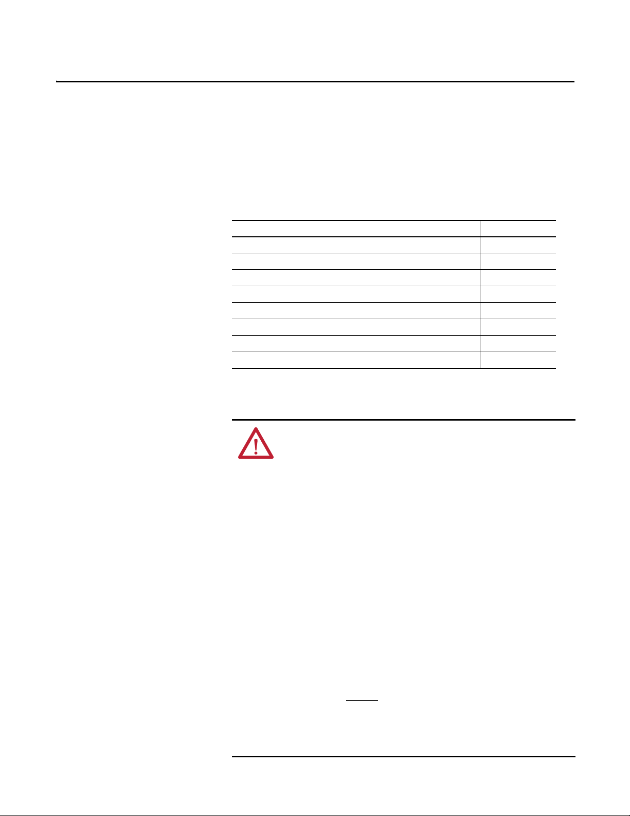
The table provides a listing of publications that contain important information
about SmartGuard 600 controller systems.
Resource Description
SmartGuard 600 Controller Installation Instructions,
publication 1752-IN001
SmartGuard Controllers Systems Safety Reference Manual,
publication 1752-RM001
DeviceNet Safety I/O Installation Instructions, publication
1791DS-IN001
Guard I/O DeviceNet Safety Modules User Manual,
publication 1791DS-UM001
DeviceNet Media Design Installation Guide, publication
DNET-UM072
Information on installing the SmartGuard 600 controller
Detailed requirements for achieving and maintaining SIL
3 with the SmartGuard controller system
Information on installing Guard I/O™ DeviceNet Safety
modules
Information on using Guard I/O DeviceNet Safety modules
Information on planning your EtherNet/IP™ network
You can view or download publications at http://
www.rockwellautomation.com/literature. To order paper copies of technical
documents, contact your local Allen-Bradley® distributor or Rockwell
Automation sales representative.
Rockwell Automation Publication 1752-UM001E-EN-P - June 2014 13
Page 14

Preface
Common Techniques Used in This Manual
These conventions are used throughout this manual:
• Bulleted lists, such as this one, provide information, not procedural steps.
• Numbered lists provide sequential steps or hierarchical information.
14 Rockwell Automation Publication 1752-UM001E-EN-P - June 2014
Page 15

Overview
Chapter 1
Introduction
About the SmartGuard 600 Controller
Top ic Pag e
About the SmartGuard 600 Controller 15
Safety Concept of the Controller 21
Additional Resource 21
The SmartGuard 600 controller (catalog numbers 1752-L24BBB and 1752L24BBBE) are programmable electronic systems featuring 16 digital inputs, 8
digital outputs, 4 test pulse sources, and connections for USB and DeviceNet™
communication. In addition, the 1752-L24BBBE controller offers EtherNet/IP
connectivity.
The SmartGuard 600 controller supports both standard and CIP Safety
communication over DeviceNet networks, and supports standard CIP
communication over EtherNet/IP networks.
The SmartGuard 600 controller is certified for use in safety applications up to
and including Safety Integrity Level (SIL) 3, according to IEC 61508,
Performance Level PL(e) according to ISO 13849-1, and Category (CAT) 4,
according to EN 954-1.
Rockwell Automation Publication 1752-UM001E-EN-P - June 2014 15
Page 16
Chapter 1 Overview
Programming
Standard Controller
Standard Slave
DeviceNet
Network
SmartGuard
Control ler
1752-L24BBB
Safety Control
RSNetWorx™ for
DeviceNet Software
DeviceNet Safety I/O
Safety Slave
Ethernet
Switch
Ethernet
Network
SmartGuard
Control ler
1752-L24BBBE
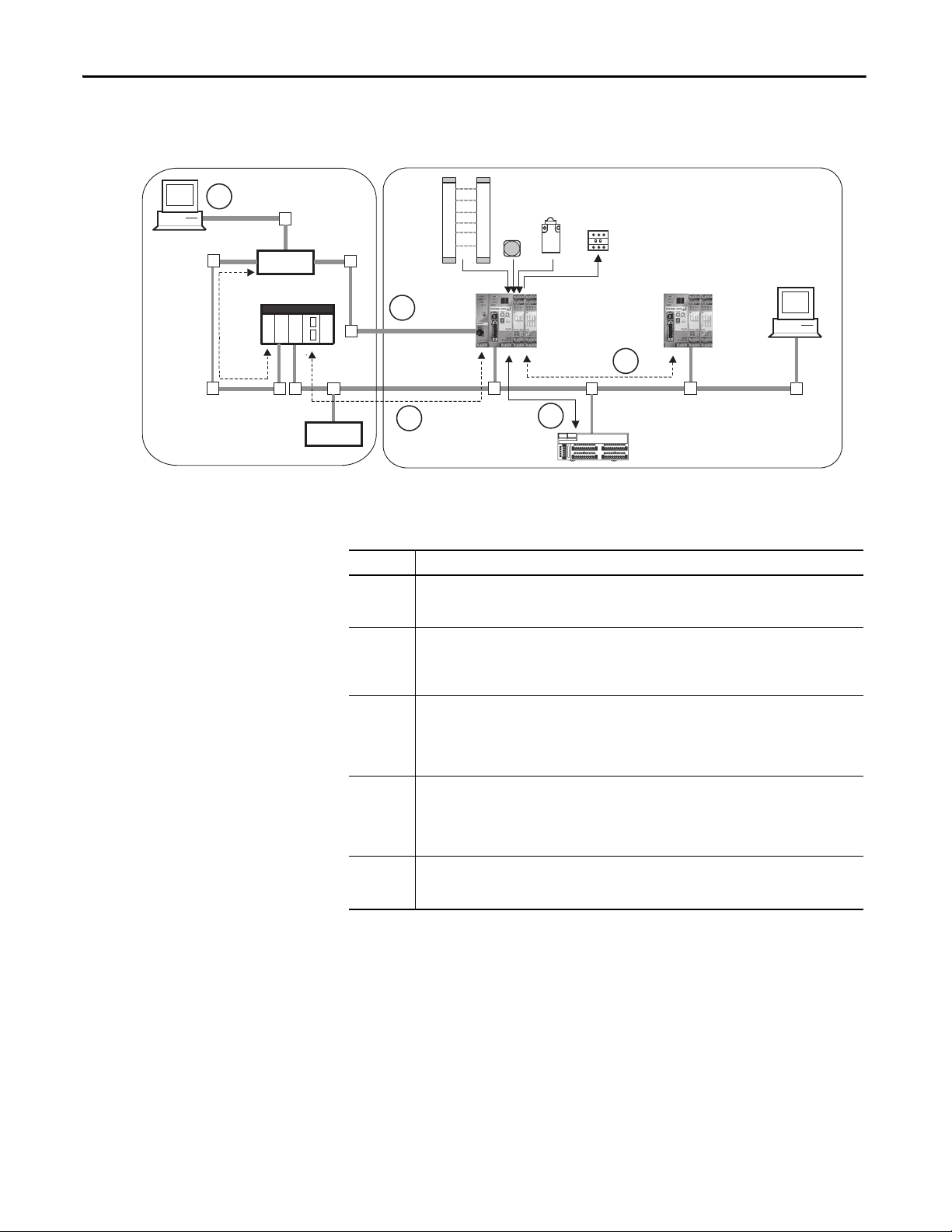
Figure 1 - SmartGuard 600 Controller Safety Control System Example
5
4
2
3
Number Description
1 As a DeviceNet safety master, the SmartGuard 600 controller can control up to 32 Guard I/O modules.
2 As a DeviceNet safety slave, the SmartGuard 600 controller looks like distributed safety I/O to a safety
3 As a DeviceNet standard slave, the SmartGuard 600 controller can look like a standard distributed I/O
4 As an E therNet/IP standard target, the SmartGu ard 600 controller comm unicates with an Ethernet/ IP
5 As a limited EtherNet/IP bridge device, the SmartGuard 600 controller lets programming tools bridge
These 1791DS and 1732DS modules are the same distributed safety I/O modules used with
GuardLogix® controllers.
master. A GuardLogix or another SmartGuard safety master can read and write safety data to the
SmartGuard slave controller. This lets you per form distrib uted safety control through the interlocking
of multiple controllers via CIP Safety on DeviceNet networks.
module and respond to explicit messages so that standard DeviceNet masters like ControlLogix®, SLC™
500, or PLC-5® controllers or an HMI can read and write information to and from the SmartGuard 600
controller. This facilitates coordination with your standard PLC application, including displaying safety
system information on an HMI.
standard originator, such as a CompactLogix™ or MicroLogix™ controller or an HMI device. The
SmartGuard controller does not support CIP Safety on EtherNet/IP communication. As a result, the
SmartGuard controller cannot control 1791ES safety modules. All safety control must be do ne over the
DeviceNet network as shown in numbers 1 and 2 above.
to DeviceNet to view and program the SmartGuard 600 controller and configure other DeviceNet
devices.
1
16 Rockwell Automation Publication 1752-UM001E-EN-P - June 2014
Page 17
Overview Chapter 1
1
3
4
6
10
5
2
7
8
9
7
Hardware
The SmartGuard 600 controller (catalog numbers 1752-L24BBB and 1752L24BBBE) features 16 digital inputs, 8 digital outputs, 4 pulse test sources, and
connections for USB and DeviceNet Safety protocol. In addition, the 1752L24BBBE controller offers EtherNet/IP connectivity.
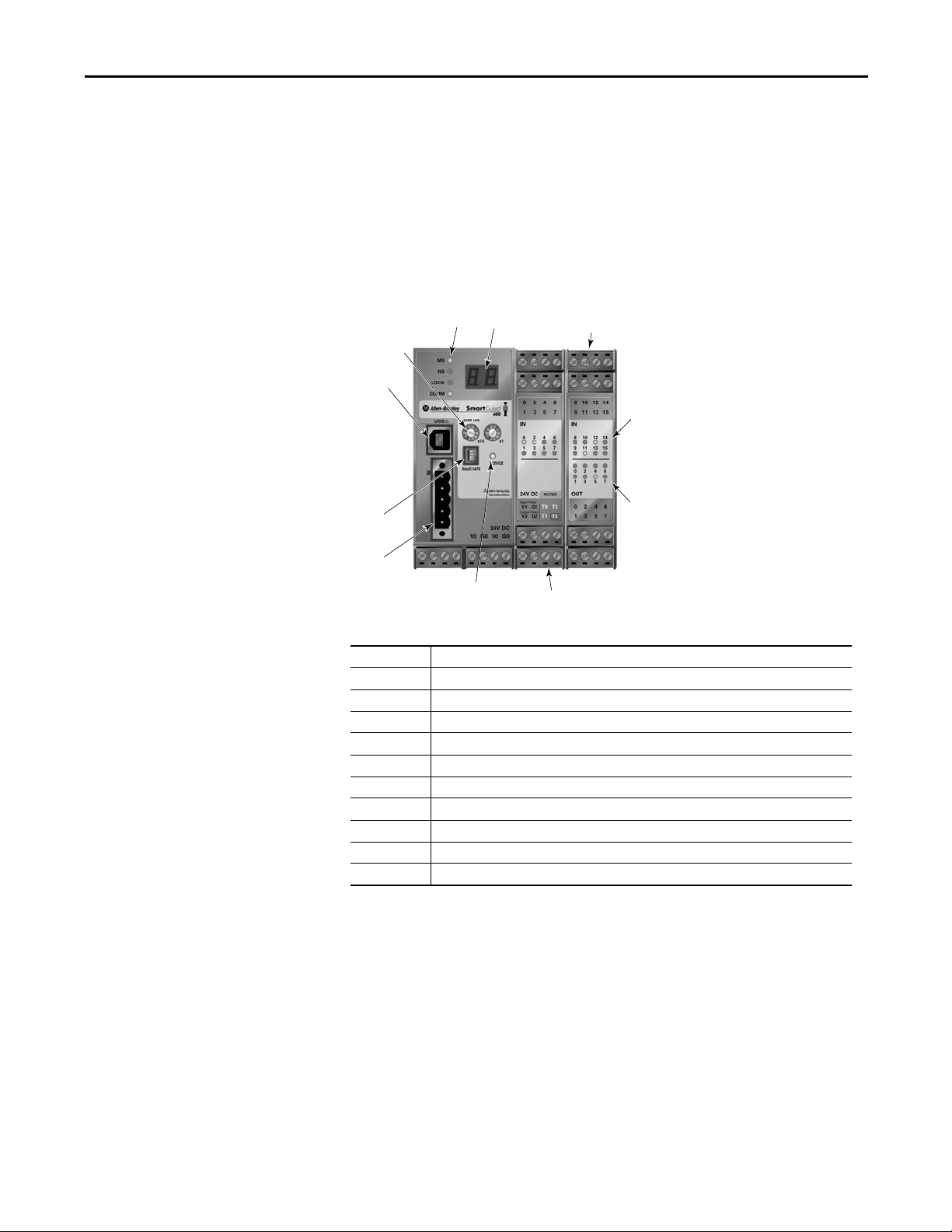
Figure 2 - SmartGuard 600 Controller (catalog number 1752-L24BBB) Features
Number Feature
1 Module status Indicators
2 Alphanumeric display
3 Node address switches
4 Baud rate switches
5USB port
6 DeviceNet communication connector
7 Terminal connectors
8 Input status indicators
9 Output status indicators
10 Service switch
Rockwell Automation Publication 1752-UM001E-EN-P - June 2014 17
Page 18
Chapter 1 Overview
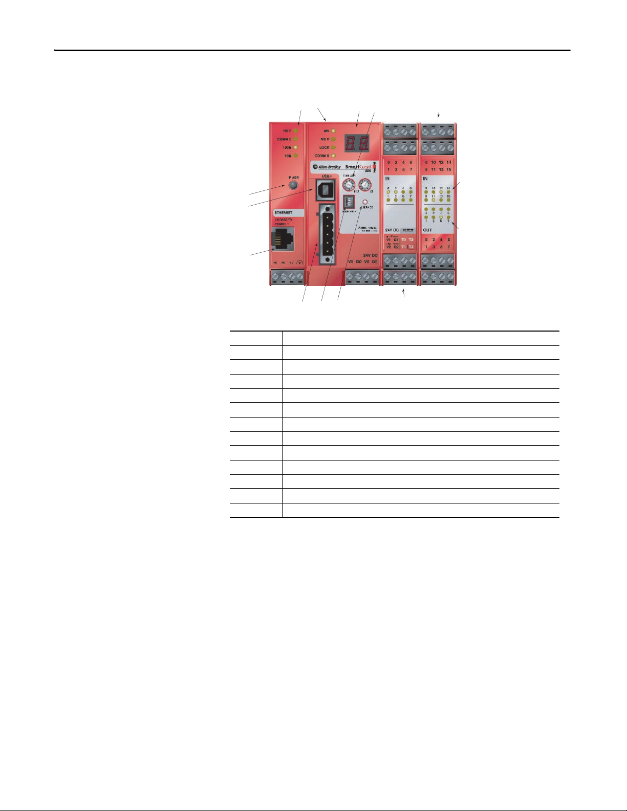
SmartGuard 600 Controller (catalog number 1752-L24BBBE) Features
1
10
5
11
12
46
Number Feature
1 Module status indicators
2 Alphanumeric display
3 Node address switches
4 Baud rate switches
5USB port
6 DeviceNet communication connector
7 Terminal connectors
8 Input status indicators
9 Output status indicators
10 IP address display switch
11 Ethernet connector
12 Service switch
27
3
8
9
7
18 Rockwell Automation Publication 1752-UM001E-EN-P - June 2014
Page 19

Overview Chapter 1
Safety Inputs
The controller has 16 local safety inputs, which support the features described
below.
• Input circuit diagnosis — Test pulse sources can be used to monitor
internal circuits, external devices, and external wiring.
• Input on- and off-delays — You can set input time filters of 0…126 ms in
multiples of the controller cycle time. Setting input on- and off-delays
helps reduce the influence of chattering and external noise.
• Dual Channel mode — You can set Dual Channel mode for pairs of
related local inputs. When Dual Channel mode is set, time discrepancies in
changes in data or input signals between two paired, local inputs can be
evaluated.
Safety Outputs
The controller has eight local safety outputs, which support the features
described below.
• Output circuit diagnosis — Test pulses can be used to diagnose the
controller’s internal circuits, external devices, and external wiring.
• Overcurrent detection and protection — To protect the circuit, an output
is blocked when an overcurrent is detected.
• Dual Channel mode — Both of two paired outputs can be set into a safety
state without depending on the user program when an error occurs in
either of the two paired local outputs.
Test Pulse Sources
Four independent test outputs are normally used in combination with safety
inputs. They can also be set for use as standard signal output terminals. The test
pulse outputs support the following features.
• Overcurrent detection and protection — To protect the circuit, an output
is blocked when an overcurrent is detected.
• Current monitoring for muting lamp — Disconnection can be detected
for the T3 terminal only.
Rockwell Automation Publication 1752-UM001E-EN-P - June 2014 19
Page 20

Chapter 1 Overview
Communication
The controller can act as a DeviceNet safety master or slave, as a DeviceNet
standard slave, or as a standalone controller when DeviceNet communication is
disabled. A single controller can function simultaneously as a safety master, safety
slave, and standard slave.
Explicit messages can be used to read controller status information. The user
program can be configured to send explicit messages from the user program. The
messages can be routed between DeviceNet and EtherNet/IP networks.
The USB port can be used to program the SmartGuard controller and to
configure devices on the DeviceNet network. The SmartGuard provides some
limited pass-through capability from USB to DeviceNet, for programming and
configuration purposes. When used in Standalone mode, the controller
communicates with the configuration software via USB communication.
Configuration and Programming
Use RSNetWorx for DeviceNet software, version 8.0 (minimum) or later
(version 9.1 is recommended), to configure, program, and monitor the status of
the 1752-L24BBB controller. Use RSNetWorx for DeviceNet software, version
9.1 or later, to configure, program, and monitor the status of the 1752-L24BBBE
controller. With RSNetWorx for DeviceNet software, you can configure the
controller by using the SmartGuard controller’s USB port or via the DeviceNet
network or EtherNet/IP network.
You also need RSLinx® software, version 2.55 or later, which lets you configure a
1752-L24BBBE controller on EtherNet/IP.
The logic editor is launched from within RSNetWorx for DeviceNet software.
Basic logic operations, such as AND and OR, and function blocks, such as
ESTOP and light curtain, are supported. A maximum of 254 logic functions and
function blocks can be used in a maximum of 32 programming pages. You can
password-protect both configuration data and project files.
Status and Error Monitoring
The controller’s internal status information and I/O data can be monitored
online by using RSNetWorx for DeviceNet software with either a USB,
DeviceNet network connection or EtherNet/IP network connection.
The status indicators and alphanumeric display on the controller provide status
and error information. When the service switch on the front of the controller is
pressed, the alphanumeric display shows the controller’s safety configuration
signature two digits at a time for a total of ten pairs of numbers.
20 Rockwell Automation Publication 1752-UM001E-EN-P - June 2014
Page 21

Overview Chapter 1
When the IP Address display switch is pressed for 1 second or longer, the display
shows the EtherNet/IP address that is set.
Errors detected by the controller are recorded in an error history log and an
EtherNet/IP history log, along with the time the error occurred. (The time is
shown as total operating time since the controller was powered up.)
Safety Concept of the Controller
The SmartGuard 600 controller is certified for use in safety applications up to
and including Safety Integrity Level (SIL) 3, according to IEC 61508,
Performance Level PL(e) according to ISO 13849-1, and Category (CAT) 4,
according to EN 954-1, in which the de-energized state is the safety state. Safety
application requirements include evaluating the probability of failure rates (PFD
and PFH), system reaction-time calculations, and functional verification tests
that fulfill SIL 3 criteria. You must read, understand, and fulfill these
requirements prior to operating a SmartGuard 600 controller-based SIL 3 or
CAT 4 safety system.
The controller uses the following mechanisms to support the integrity of safety
data.
• Safety network number (SNN) — A unique number that identifies the
safety network. CIP safety nodes must have a unique SNN and DeviceNet
network address.
• Configuration signature — The combination of an ID number, date, and
time that uniquely identifies a specific configuration for a safety device.
• Configuration lock (or safety-lock) — After the configuration data has
been downloaded and verified, you can lock the controller’s configuration
to prevent it from being modified.
• Password protection — The controller’s configuration can be protected by
the use of an optional password. If you set a password, download, locking,
unlocking, resetting, and changing the status of the controller requires a
password to perform.
Additional Resource
You must create and document a clear, logical, and visible distinction between the
safety and any standard portions of the application.
Refer to the SmartGuard Controllers Safety Reference Manual, publication
1752-RM001, for information on SIL 3 and CAT 4 safety system requirements,
including functional verification test intervals, system reaction time, and PFD/
PFH values.
Rockwell Automation Publication 1752-UM001E-EN-P - June 2014 21
Page 22

Chapter 1 Overview
Notes:
22 Rockwell Automation Publication 1752-UM001E-EN-P - June 2014
Page 23
Chapter 2
Installing and Wiring the SmartGuard 600
Controller
Introduction
General Safety Information
Top ic Pag e
General Safety Information 23
Understanding Node Addressing 25
Set the Node Address 26
Setting the Communication Rate 26
Mount the SmartGuard Controller 29
Grounding the SmartGuard Controller 30
Connecting a Power Supply 30
Wiring the SmartGuard 600 Controller 34
ATTENTION: Environment and Enclosure
This equipment is intended for use in Pollution Degree 2 Industrial environment, in
Overvoltage Category II applications (as defined in IEC publication 60664-1), at
altitudes up to 2000 m (6562 ft) without derating.
This equipment is considered Group 1, Class A industrial equipment according to
IEC/CISPR Publication 11. Without appropriate precautions, there may be potential
difficulties ensuring electromagnetic compatibility in other environments due to
conducted as well as radiated disturbance.
This equipment is supplied as open type equipment. It must be mounted within an
enclosure that is suitably designed for those specific environmental conditions that
will be present and appropriately designed to prevent personal injury resulting
from accessibility to live parts. The enclosure must have suitable flame-retardant
properties to prevent or minimize the spread of flame, complying with flame
spread rating or 5VA, V2, V1, V0 (or equivalent) if non-metallic. The interior of the
enclosure must be accessible only by the use of a tool. Subsequent sections of this
publication may contain additional information regarding specific enclosure type
ratings that are required to comply with certain product safety certifications.
In addition to this publication, see:
· Industrial Automation Wiring and Grounding Guidelines, Allen-Bradley
publication 1770-4.1
.
· NEMA Standards publication 250 and IEC publication 60529, as applicable, for
explanations of the degrees of protection provided by different types of
enclosure.
Rockwell Automation Publication 1752-UM001E-EN-P - June 2014 23
Page 24
Chapter 2 Installing and Wiring the SmartGuard 600 Controller
Table 1 - North American Hazardous Location Approval
The following information applies when operating this equipment in
hazardous locations
Products marked CL I, DIV 2, GP A, B, C, D are suitable for use in Class I Division 2 Groups
A, B, C, D, Hazardous Locations and nonhazardous locations only. Each product is
supplied with markings on the rating nameplate indicating the hazardous location
temperature code. When combining products within a system, the most adverse
temperature code (lowest T number) may be used to help determine the overall
temperature code of the system. Combinations of equipment in your system are subject
to investigation by the local Authority Having Jurisdiction at the time of installation.
EXPLOSION HAZARD
·Do not disconnect equipment unless power has been
removed or the area is known to be nonhazardous.
·Do not disconnect connections to this equipment unless
power has been removed or the area is known to be
nonhazardous. Secure any external connections that mate
to this equipment by using screws, sliding latches,
threaded connectors, or other means provided with this
product.
·Substitution of components may impair suitability for
Class I, Division 2.
·If this product contains batteries, they must only be
changed in an area known to be nonhazardous.
ATTENTION: Safety Programmable Electronic Systems (PES)
Personnel responsible for the application of safety-related programmable
electronic systems (PES) shall be aware of the safety requirements in the
application of the system and shall be trained in using the system.
Informations sur l’utilisation de cet équipement en environnements dangereux
Les produits marqués CL I, DIV 2, GP A, B, C, D ne conviennent qu’à une utilisation en
environnements de Classe I Division 2 Groupes A, B, C, D dangereux et non dangereux. Chaque
produit est livré avec des marquages sur sa plaque d’identification qui indiquent le code de
température pour les environnements dangereux. Lorsque plusieurs produits sont combinés
dans un système, le code de température le plus défavorable (code de température le plus
faible) peut être utilisé pour déterminer le code de température global du système. Les
combinaisons d’équipements dans le système sont sujettes à inspection par les autorités
locales qualifiées au moment de l’installation.
RISQUE D’EXPLOSION
·Couper le courant ou s’assurer que l’environnement est classé
non dangereux avant de débrancher l'équipement.
·Couper le courant ou s'assurer que l’environnement est classé
non dangereux avant de débrancher les connecteurs. Fixer tous
les connecteurs externes reliés à cet équipement à l'aide de vis,
loquets coulissants, connecteurs filetés ou autres moyens
fournis avec ce produit.
·La substitution de composants peut rendre cet équipement
inadapté à une utilisation en environnement de Classe I,
Division 2.
·S’assurer que l’environnement est classé non dangereux avant
de changer les piles.
ATTENTION: Prevent Electrostatic Discharge
This equipment is sensitive to electrostatic discharge, which can cause internal
damage and affect normal operation. Follow these guidelines when you handle
this equipment.
· Touch a grounded object to discharge potential static.
· Wear an approved wrist grounding strap.
· Do not touch connectors or pins on component boards.
· Do not touch circuit components inside the equipment.
· Use a static-safe workstation, if available.
· Store the equipment in appropriate static-safe packaging when not in use.
ATTENTION: Protective Debris Strip
Do not remove the protective debris strip until after the controller and all the other
equipment near the controller is mounted and wiring is complete.
Once wiring is complete, remove the protective debris strip. Failure to remove the
strip before operating can cause overheating.
24 Rockwell Automation Publication 1752-UM001E-EN-P - June 2014
Page 25
Installing and Wiring the SmartGuard 600 Controller Chapter 2
ATT EN TI ON : Serious injury may occur due to the loss of required safety
function.
· Do not use test outputs as safety outputs.
· Do not use DeviceNet standard I/O data or explicit message data as safety data.
· Do not use status indicators for safety operations.
· Do not connect loads beyond the rated value to safety outputs or test outputs.
· Wire the controller properly so that the 24V dc line does not accidentally touch
the outputs.
· Ground the 0V line of the power supply for external output devices so that the
devices do not turn on when the safety output line or test output line is
grounded.
· Do not dismantle, repair, or modify the controller. Doing so may impair the
safety functions.
Understanding Node Addressing
To communicate on the DeviceNet network, each device requires its own
address. Follow the recommendations below when assigning addresses to the
devices on your network.
Table 2 - Node Address Recommendations
Give this device This address Notes
Scanner 0 If you have multiple scanners, give them the lowest
Any device on your network, except
the scanner
RSNetWorx for DeviceNet
workstation
No device 63 Leave address 63 open. This is where a non-
1…61 Gaps between addresses are allowed and have no
62 If you connect a computer directly to the DeviceNet
addresses in sequence.
effect on system performance. Leaving gaps gives you
more flexibility as you develop your system.
network, use address 62 for the computer or
bridging/linking device.
commissioned node typically enters the network.
The standard DeviceNet network assigns communication priority based on the
device’s node number. The lower the node number, the higher the device’s
communication priority. This priority becomes important when multiple nodes
are trying to communicate on the network at the same time.
DeviceNet safety nodes have additional priority on the network, regardless of
node number. DeviceNet safety communication from devices with lower node
numbers have priority over DeviceNet safety communication from devices with
higher node numbers.
Rockwell Automation Publication 1752-UM001E-EN-P - June 2014 25
Page 26

Chapter 2 Installing and Wiring the SmartGuard 600 Controller
IMPORTANT
IMPORTANT
IMPORTANT
Set the Node Address
Set the node address before you mount the controller.
Turn off power to the controller before setting the node address or
communication rate via the switches.
Do not change the switch settings while the power supply is on. The controller
will detect this as a change in the configuration and will switch to the ABORT
mode.
Use a small flathead screwdriver to set the node address by using the two rotary
switches on the front panel of the controller. Use care not to scratch the switches.
Values from 00…63 are valid. The default setting is 63.
Follow these steps to set the node address.
1. Set the tens digit of the node address (decimal) by turning the left rotary
switch.
2. Set the ones digit by turning the right rotary switch.
3. To allow the node address to be set by using RSNetWorx for DeviceNet
software, set the rotary switches to a value from 64…99.
Setting the Communication Rate
A node address duplication error will occur if the same node address is set for
more than one node.
Set the communication rate before you mount the controller.
Turn off power to the controller before setting the node address or
communication rate via the switches.
Do not change the switch settings while the power supply is on. The controller
will detect this as a change in the configuration and will switch to the ABORT
mode.
DeviceNet Communication
The default communication rate for a DeviceNet network is 125 Kbps.
26 Rockwell Automation Publication 1752-UM001E-EN-P - June 2014
Page 27

Installing and Wiring the SmartGuard 600 Controller Chapter 2
If you choose to use a different communication rate, the length of the trunkline
and types of cable determine which communication rates your application can
support.
Table 3 - DeviceNet Communication Rates and Cable Lengths
Communication Rate Distance, max Cumulative Drop
Flat Cable Thick Cable Thin Cable
125 Kpbs 420 m (1378 ft) 500 m (1640 ft) 100 m (328 ft) 156 m (512 ft)
250 Kpbs 200 m (656 ft) 250 m (820 ft) 100 m (328 ft) 78 m (256 ft)
500 Kpbs 75 m (246 ft) 100 m (328 ft) 100 m (328 ft) 39 m (128 ft)
Line Length
Rockwell Automation Publication 1752-UM001E-EN-P - June 2014 27
Page 28
Chapter 2 Installing and Wiring the SmartGuard 600 Controller
IMPORTANT
1
2
3
4
O
N
ON
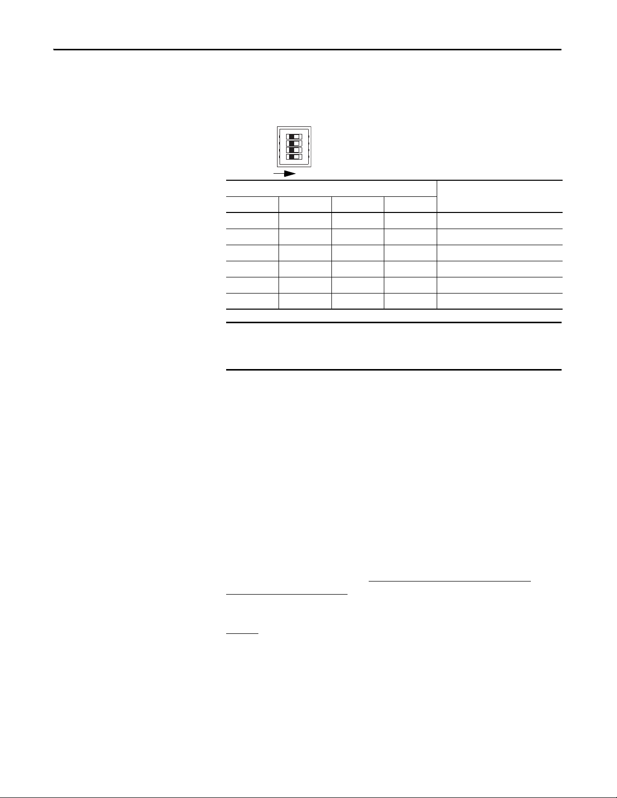
Set the communication rate by using the DIP switch on the front of the
controller.
Figure 3 - Communication Rate Dip Switch
DIP Switch Pin Communication Rate
1234
OFF OFF OFF OFF 125 Kbps
ON OFF OFF OFF 250 Kbps
OFF ON OFF OFF 500 Kbps
ON ON OFF OFF Set by software
ON or OFF ON or OFF ON OFF Set by software
ON or OFF ON or OFF ON or OFF ON Automatic baud rate detection
If you change the communication rate of your network, make sure that all
devices change to the new communication rate. Mixed communication rates
produce communication errors.
If you set other devices to autobaud, at least one device on the network must have
a communication rate established. If you set all devices on the network to
autobaud, they will not be able to establish a communication rate and will not
communicate with each other.
Ethernet Communication
We recommend connecting the module to the network via a 100 Mbps Ethernet
switch, which will help reduce collisions and lost packets and increase bandwidth.
The 1752-L24BBBE controller is shipped with BOOTP enabled for setting the
IP address. You can use any commercially available BOOTP server. If you do not
have BOOTP Server capabilities on your network, download the free Rockwell
Automation BOOTP server from http://www.rockwellautomation.com/
rockwellsoftware/download/.
To set the IP address by using the Rockwell Automation BOOTP utility, refer to
page 51
.
The following table provides additional EtherNet/IP information.
28 Rockwell Automation Publication 1752-UM001E-EN-P - June 2014
Page 29
Mount the SmartGuard
IMPORTANT
Latch
Top Sl ot
DIN Rail
Controller
Installing and Wiring the SmartGuard 600 Controller Chapter 2
For detailed information on EtherNet/IP communication, refer to the EtherNet/
IP Performance and Application Solution, publication ENET-AP001
Attribute Value
Number of CIP packets 2
Allowable Unit communication bandwidth 3000 pps
Explicit message communication 502 B
(1) PPS is packets Per second. It indicates the number of send or receive packets that can be processed per second.
(2) The maximum message length for class 3 connection and UCMM connection.
(1)
(2)
.
For effective cooling:
· mount the controller on a horizontal DIN rail. Do not mount the controller
vertically.
· provide a gap of at least 50 mm (2.0 in.) above and below the controller
and 5 mm (0.20 in.) on each side.
· select a location where air flows freely or use an additional fan.
· do not mount the controller over a heating device.
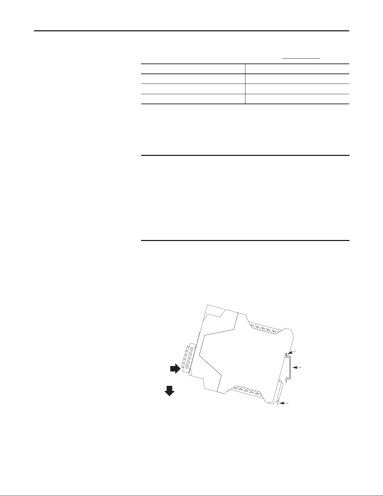
The controller cannot be panel-mounted. Follow these steps to mount the
controller to an EN50022-35x7.5 or EN50022-35x15 DIN rail.
1. Hook the top slot over the DIN rail.
2. Snap the bottom of the controller into position while pressing the
controller down against the top of the rail.
3. Attach end plates to each end of the DIN rail.
To remove the controller from the DIN rail, use a flathead screwdriver to pull
down the latch and lift the controller off of the rail. The 1752-L24BBB
controller has one latch and the 1752-L24BBBE controller has two latches on the
bottom of the controller.
Rockwell Automation Publication 1752-UM001E-EN-P - June 2014 29
Page 30
Chapter 2 Installing and Wiring the SmartGuard 600 Controller
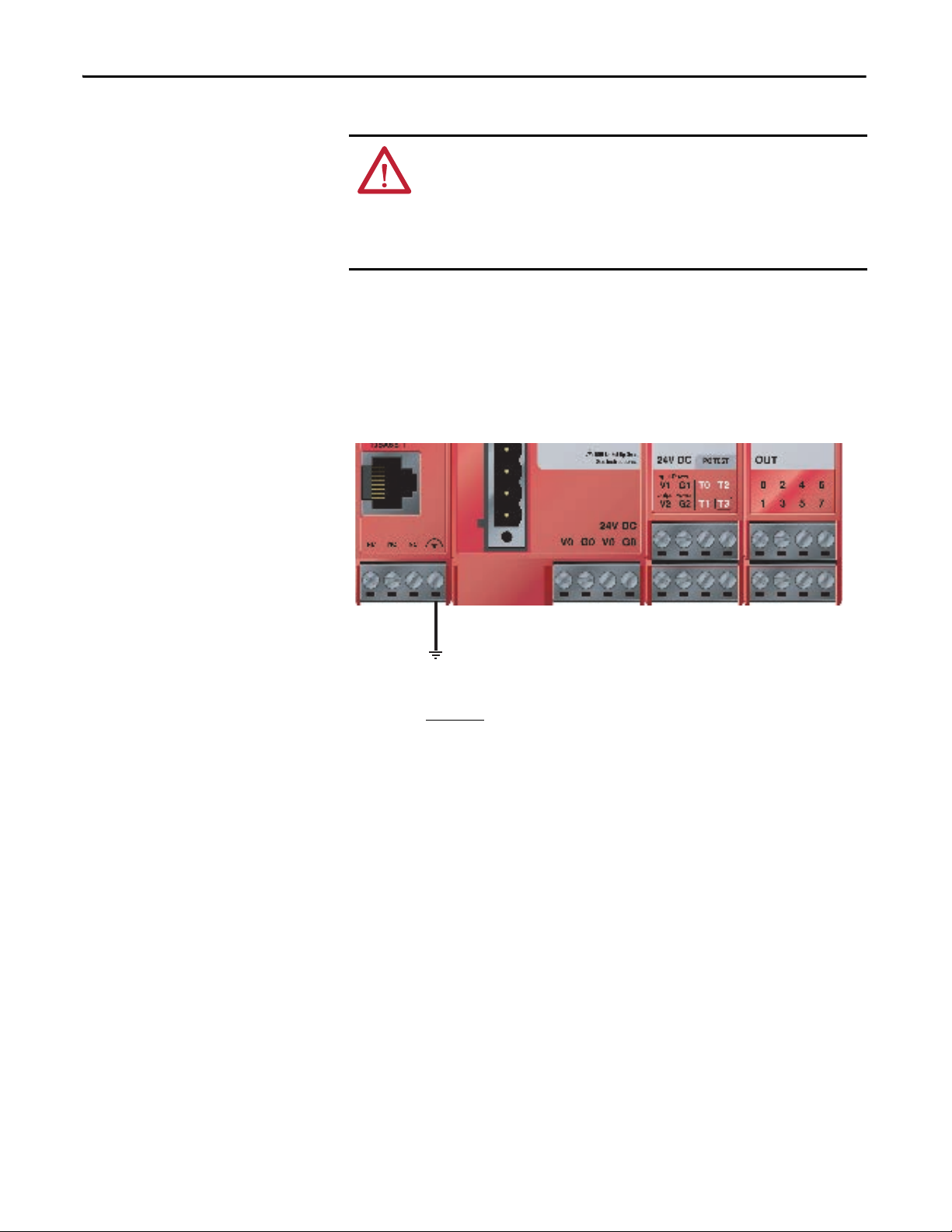
Grounding the SmartGuard Controller
You must provide an acceptable grounding path for each device in your
application. Functionally ground the controller through its V0/G0 power
connection.
In addition, if you are using the 1752-L24BBBE controller, you should connect
the Ethernet ground terminal to an acceptable ground.
Figure 4 - Ethernet Ground
ATT EN TI ON : This product is grounded through the DIN rail to chassis ground.
Use zinc plated yellow-chromate steel DIN rail to assure proper grounding. The
use of other DIN rail materials (for example, aluminum or plastic) that can
corrode, oxidize, or are poor conductors, can result in improper or intermittent
grounding. Secure DIN rail to mounting surface approximately every 200 mm
(7.8 in.) and use end anchors appropriately.
Connecting a Power Supply
Refer to the Industrial Automation Wiring and Grounding Guidelines,
publication 1770-4.1
Power for the controller is provided via an external 24V dc power source. The
output hold time must be 20 ms or longer.
To comply with the CE Low Voltage Directive (LVD), DeviceNet connections
and I/O must be powered by a dc source compliant with Safety Extra Low
Voltage (SELV) or Protected Extra Low Voltage (PELV).
To comply with UL restrictions, DeviceNet connections and I/O must be
powered by dc sources whose secondary circuits are isolated from the primary
circuit by double insulation or reinforced insulation. The dc power supply must
satisfy the requirements for Class 2 circuits or limited voltage/current circuits
defined in UL 508.
, for additional information.
30 Rockwell Automation Publication 1752-UM001E-EN-P - June 2014
Page 31

Installing and Wiring the SmartGuard 600 Controller Chapter 2
TIP
+-
+-
+-
The following Allen-Bradley 1606 power supplies are SELV- and PELVcompliant, and they meet the isolation and output hold-off time requirements
of the SmartGuard 600 controller:
· 1606-XLP30E
· 1606-XLP50E
· 1606-XLP50EZ
The SmartGuard controller has three V/G terminal pairs that require a power
connection. There are two V0/G0 pairs, but because they are internally
connected, you only need to connect one V0/G0 pair. You can use the other pair
to distribute power to other devices.
Figure 5 - Power Supply Connections
· 1606-XLP72E
· 1606-XLP95E
· 1606-XLDNET4
· 1606-XLSDNET4
Making Communication Connections
ATT EN TI ON : Do not connect or disconnect the communication cable with
power applied to this controller or any device on the network, because an
electrical arc can occur. This could cause an explosion in hazardous location
installations. Be sure that power is removed or the area is nonhazardous before
proceeding.
You can configure the network and controller on the DeviceNet network by
using a 1784-PCD card inside your personal computer and RSNetWorx for
DeviceNet software. You may also configure the network and controller by using
the controller’s USB port and RSNetWorx for DeviceNet software. In addition,
you can configure the controller using RSNetWorx for DeviceNet software by
connecting to the EtherNet/IP port and routing down to DeviceNet network.
Connect to the DeviceNet port
Follow these steps to connect to the DeviceNet port.
Rockwell Automation Publication 1752-UM001E-EN-P - June 2014 31
Page 32

Chapter 2 Installing and Wiring the SmartGuard 600 Controller
D
D
D
D
D
1
2
3
4
5
Wire No. Wire Color Connects to
V+ Red V+
CAN H White CAN H
Drain — Drain
CAN L Blue CAN L
V- Bl ack V-
For detailed DeviceNet connection information, refer to the DeviceNet Media
Design Installation Guide, publication DNET-UM072
Industrial Automation Wiring and Grounding Guidelines, publication 1770-4.1
1. Wire the connector according to the colors on the connector.
2. Attach the connector to the
DeviceNet port.
3. Tighten the screws to 0.25…0.3 N•m (2.21…2.65 lb•in).
. Also refer to the
.
32 Rockwell Automation Publication 1752-UM001E-EN-P - June 2014
Page 33

Installing and Wiring the SmartGuard 600 Controller Chapter 2
IMPORTANT
Connecting to USB Port
Connect the USB communication connector to your personal computer when
you want to configure the network and controller by using RSNetWorx for
DeviceNet software. Use a commercially available USB-A to USB-B male/male
cable to make the connection.
ATT EN TI ON : To reduce the potential for electromagnetic interference, the USB
cable length must be less than 3 m (10 ft).
The USB port is intended for temporary programming purposes only and is not
intended for permanent connection.
ATT EN TI ON : If you connect or disconnect the USB cable with power applied to
this module or any device on the USB network, an electrical arc could occur. This
could cause an explosion in hazardous location installations. Be sure that power
is removed or the area is nonhazardous before proceeding.
Connecting to the Ethernet port
Depending on where you plan to route your cable you must select the correct
cable for the environment. Shielded cable performs better than non shielded
cable in industrial environments. In particular, if your application is in a high
noise environment or your cable must be run in close proximity to noise radiating
sources then you should plan to use shielded cables.
You should consider shielded cables if your application includes one or more of
the following:
• spot welding control
• Motor Control Centers
• drives greater than 10 Hp
• induction welding processes
• proximity to high-power RF radiation
• electrostatic processes
• high current devices (greater than 100 A)
Shields play an important role in providing noise immunity for your system.
However, an improperly installed shielded cable can cause problems due to
voltage offsets in your grounding system. To help minimize the effects of
ground offsets you will need to isolate the shield at one end of the cable. In this
case the shield should be isolated at the deice, not at the switch.
Use an RJ45 connector to connect the controller to the EtherNet/IP network.
When connecting to the SmartGuard controller to a switch or a hub, use a
Rockwell Automation Publication 1752-UM001E-EN-P - June 2014 33
Page 34

Chapter 2 Installing and Wiring the SmartGuard 600 Controller
standard Ethernet cable. When connecting the SmartGuard controller directly to
your personal computer or a NIC card, use a cross-over (null modem) cable.
Pin No. Pin Name Pin placement
8 Not used
7 Not used
6RD-
5 Not used
4 Not used
3RD+
2TD-
1TD+
ATT EN TI ON : The cable length must be less then 100 m (328 ft) between hub
and nodes.
WARNING: If you connect or disconnect the Ethernet cable with power applied
to this controller or any other device on this network, an electrical arc can occur.
This could cause an explosion in hazardous location installations. Be sure that
power is removed or the area is nonhazardous before proceeding.
8
1
Wiring the SmartGuard 600 Controller
Use cables of 30 m (98 ft) or less.
Attribute Value
Wire t ype Coppe r
Wiring c ategor y
Wire size For power supply and I/O, use 0.2…2.5 mm2 (12…24 AWG) solid wire, or
I/O Terminal Screw Torque 0.56…0.79 N•m (5…7 lb•in)
(1) Use this Conductor Category information for planning conductor routing. Refer to Industrial Automation Wiring and Grounding
Guidelines, publication 1770-4.1
Terminal Designation Description
(1)
V0 Power terminal for internal circuit (logic).
G0 Power terminal for internal circuit (logic).
V1 Power terminal for input circuits and test outputs.
G1 Power terminal for input circuits and test outputs.
V2 Power terminal for safety outputs.
G2 Power terminal for safety outputs.
2 - on power, signal, and communication ports
0.34…1.5 mm2 (16…22 AWG) stranded flexible wire. Before connecting,
prepare stranded wires by attaching ferrules with plastic insulation collars
(DIN 46228-4 standard compatible).
.
34 Rockwell Automation Publication 1752-UM001E-EN-P - June 2014
Page 35

Installing and Wiring the SmartGuard 600 Controller Chapter 2
IMPORTANT
SmartGuard 600
Control ler
V1
Tx
INx
G1
24V dc
4.5 mA Typical
IN0…IN15 Terminals for safety inputs.
T0…T3 These are test output terminals that can provide pulse test sources for safety inputs
OUT0…OUT7 Terminals for safety outputs.
IN0…IN15. T3 can also support wire off detection and burned out bulb detection for a
load such as a muting lamp.
ATT EN TI ON : If you connect or disconnect wiring while the field-side power is
applied, an electrical arc can occur. This could cause an explosion in hazardous
location installations. Be sure that power is removed or the area is
nonhazardous before proceeding.
ATT EN TI ON : If you connect or disconnect the removable terminal block (RTB)
while the field-side power is applied, an electrical arc can occur. This could
cause an explosion in hazardous location installations. Be sure that power is
removed or the area is nonhazardous before proceeding.
Prepare stranded wires by attaching ferrules with plastic insulation covers
(compliant with the DIN 46228-4 standard). Ferrules similar in appearance but
not compliant may not match the terminal block on the controller.
When safety devices are connected via test outputs to an input circuit on the
SmartGuard controller, we recommend the length of the wire to be 30 m (98.4 ft)
or less.
Figure 6 - Input Devices with Mechanical Contact Outputs
Devices, such as light curtains, with current-sourcing PNP semiconductor
outputs send a signal to the SmartGuard 600 controller safety input terminal and
do not use a test output.
Rockwell Automation Publication 1752-UM001E-EN-P - June 2014 35
Page 36

Chapter 2 Installing and Wiring the SmartGuard 600 Controller
SmartGuard 600
Control ler
V1
Tx
INx
G1
24V dc
24V dc
OSSDx
GND
4.5 mA Typical
SmartGuard 600
Control ler
V2
G2
24V dc
OUTx
0.5 A Max
Load
Figure 7 - Input Devices with PNP Semiconductor Outputs
Wire Output Devices
ATT EN TI ON : Serious injury may occur due to a loss of required safety functions.
Do not connect loads beyond the rated value of safety or test outputs.
Do not use test outputs as safety outputs.
Wire the controller properly so that the 24V dc lines do not touch the safety or test
outputs.
Do not apply the power supply to the test output terminals.
Ground the 0V line of the power supply for external output devices so that the
devices do not turn on when the safety output line or the test output line is
grounded.
Separate I/O cables from high voltage or high current lines.
Figure 8 - Output Device Wiring
36 Rockwell Automation Publication 1752-UM001E-EN-P - June 2014
Page 37

Wiring Examples
E1 and E2: 24V dc Power Supplies
S1: Emergency Stop Switch
S2: Reset Switch (N.O. Contact)
KM1 and KM2: Contactors
Connect a 24V dc power supply to terminals V0 and G0, the power supply terminals for internal circuits.
Connect a 24V dc power supply to terminals V0 and G0, the power supply terminals for internal circuits.
Open
E1 and E2: 24V dc Power Supplies
S1: Limit Switch 1
S2: Limit Switch 2
S3: Reset Switch
KM1 and KM2: Contactors
Figure 9 - ESTOP
Installing and Wiring the SmartGuard 600 Controller Chapter 2
11 21
12 22
S1
Figure 10 - Safety Gate
S1
I0
I1
V1
V2 G 2
E2
E1
I2
I3
S2
G1 T 0
I0
I1
I4
I6
I5
I7
T2
T3
T1
I4
I2
I5
I3
I8
I9
O0
O1
I6
I7
I1 2
I1 0
I1 3
I1 1
O2 O4 O6
O3 O5
I10
I8
I9
I12
I11
I13
I1 4
I1 5
O7
I14
I15
KM 1 - N C
KM 2 - N C
KM1
KM2
KM 1 KM 2
KM1-NC
M
Rockwell Automation Publication 1752-UM001E-EN-P - June 2014 37
V1
V2 G2
E2
E1
S3
G1 T0
KM2-NC
KM1
T2
T1
T3
O0
O1
O2 O4 O6
O3 O5
KM2
KM2
O7
KM1
M
Page 38

Chapter 2 Installing and Wiring the SmartGuard 600 Controller
V1
G1 T 0
T1
I1
T1
T0
I0
I3
I5
I2
I4
I6
I7
T2
T3
E1
S1 1
O1
O0
V2 G 2
O3 O5
O2 O 4 O6
O7
E2
KM 1KM 2
I9
I8
I1 1
I1 3
I1 0
I1 2
I1 4
I1 5
KM 1 - N C
KM 2 - N C
S1 2
M
KM 1
KM 2
E1 and E2: 24V dc Power Supplies
S11 and S12: Two-hand Switches
KM1 and KM2: Contactors
Connect a 24V dc power supply to terminals V0 and G0, the power supply terminals for internal circuits.
KM 1
KM 1
KM
E2
E1
2
KM 2
KM 1-N.C.
KM 2- N.C.
I0 I2 I4 I6
I1 I3 I5 I7
I8 I10 I12 I14
I9 I11 I13 I15
V1 G1 T0 T2
V2 G2 T1 T3
O0 O2 O4 O6
O1 O3 O5 O7
E1 and E2: 24V dc Power Supplies
KM1 and KM2: Contactors
Connect a 24V dc power supply to terminals V0 and G0, the power supply terminals for internal circuits.
Receiver
OSSD1
Receiver
OSSD2
Figure 11 - Two-hand Switch
Figure 12 - Light Curtain
38 Rockwell Automation Publication 1752-UM001E-EN-P - June 2014
Page 39

Figure 13 - User Mode Switch
I0 I2
I4 I 6
I8 I1 0 I12 I1 4
V1 G 1 T0 T2
V2 G 2 T1 T3
O0 O2 O4 O 6
O1 O3 O5 O7
E2
E1 and E2: 24V dc Power Supplies
S1: User Mode Switch
Connect a 24V dc power supply to terminals V0 and G0, the power supply terminals for
internal circuits.
Installing and Wiring the SmartGuard 600 Controller Chapter 2
S1
I1 I3 I5 I7
E1
I9 I11 I13 I1 5
Rockwell Automation Publication 1752-UM001E-EN-P - June 2014 39
Page 40

Chapter 2 Installing and Wiring the SmartGuard 600 Controller
Notes:
40 Rockwell Automation Publication 1752-UM001E-EN-P - June 2014
Page 41

Set Up Your DeviceNet Network
TIP
IMPORTANT
Chapter 3
Introduction
Connecting a Computer to the DeviceNet Network
Top ic Pa ge
Connecting a Computer to the DeviceNet Network 41
Commission All Nodes 42
Browse the Network 44
Configuration Signature 44
Safety Reset (optional) 45
Setting Passwords (optional) 47
To access a network, either:
• connect directly to the network.
• connect to a different network and browse to the desired network via a
linking device.
You can browse the DeviceNet and EtherNet/IP networks through the USB
port of the SmartGuard controller.
The SmartGuard USB to DeviceNet bridging capability is limited. For
example, you cannot configure a 1734-ADN nor any POINT I/O™ modules.
You also cannot configure a 1753-DNSI module through the SmartGuard
controller. Use a 1784-PCD card instead for these operations.
Once you choose a network:
• install the communication card, if required.
• determine any network parameters for the computer, such as a network
address.
• connect the computer to the network by using the correct cable.
The first time you connect a SmartGuard controller to your personal computer
by using the USB port, Windows goes through its device recognition sequence
and prompts you for USB drivers. The driver is on the RSLinx Classic CD in the
SmartGuardUSB-KernelDrivers folder.
Configure a Driver for the Network
1. Start RSLinx software.
2. Click Configure Driver.
Rockwell Automation Publication 1752-UM001E-EN-P - June 2014 41
Page 42

Chapter 3 Set Up Your DeviceNet Network
IMPORTANT
3. From the pull-down the list of Available Driver Types, add the driver for
your network.
Network Driver
RS-232 RS-232 DF1 devices
EtherNet/IP Ethernet devices
DeviceNet DeviceNet drivers
USB SmartGuard USB Driver
4. Configure the driver.
The settings you make are dependent upon the network you choose and
whether you are using a communication card or interface module.
Make Sure the Driver Works
1. Check the Configure Drivers dialog box to make sure that the driver is
running.
Commission All Nodes
2. Close the dialog box.
3. Open the RSWho dialog box.
4. Double-click the driver to see the network.
If you have not specifically set the node address and communication rate of your
devices by using hardware switches, you will need to commission each device by
using RSNetWorx for DeviceNet software.
Before you can use RSNetWorx for DeviceNet’s Node Commissioning tool, your
computer and your DeviceNet devices must be connected to the DeviceNet
network.
Use the Node Commissioning tool in RSNetWorx for DeviceNet software to set
the node address and/or communication rate of the SmartGuard controller and
other DeviceNet devices.
Follow the guidelines on page 26
when selecting node addresses for your
DeviceNet network.
To allow the node address to be set by using the Node Commissioning tool in
RSNetWorx for DeviceNet software, set the node address rotary switch on the
controller to a value from 64…99.
See page 26
for information on setting the node address by using the rotary
switch.
42 Rockwell Automation Publication 1752-UM001E-EN-P - June 2014
Page 43

Set Up Your DeviceNet Network Chapter 3
IMPORTANT
IMPORTANT
Follow these steps to use the Node Commissioning tool.
1. Within RSNetWorx for DeviceNet software, choose Tools>Node
Commissioning.
2. Click Browse on the Node Commissioning dialog box to select a device by
browsing the network.
You can browse through the SmartGuard USB port or the Ethernet/IP
port to reach the DeviceNet port.
3. Select the DeviceNet network in the left panel.
4. Select the device you want to commission in the right panel and click OK.
5. Select the desired value if you want to change the communication rate of
the device.
The communication rate of the device will not update until the device is
power-cycled or reset.
6. On the Node Commissioning dialog box, type the new address for the
device and click Apply.
A confirmation message tells you if the operation was successful.
To change the node address of a Safety device, you must first reset the
safety network number (SNN) to an uninitialized state by performing a
safety reset as described on page 45
.
Rockwell Automation Publication 1752-UM001E-EN-P - June 2014 43
Page 44

Chapter 3 Set Up Your DeviceNet Network
Browse the Network
Follow these steps to browse the network.
1. Determine your connection type.
If you are using this connection
type
DeviceNet network Go to step 2.
USB Port Follow these steps to configure a path to the DeviceNet network.
EtherNet/IP Network Follow these steps to configure a path to the DeviceNet network.
Then
A. From the Network menu, choose Properties.
B. On the DeviceNet dialog box, click Set Online Path.
C. On the Browse for Network dialog box, select the desired
path and click OK.
A. From the Network menu, choose Properties.
B. On the DeviceNet dialog box, click Set Online Path.
C. On the Browse for Network dialog box, select the desired
path and click OK.
2. Click the online icon .
3. Wait for the Browse Network operation to complete.
As the network is browsed, all of the devices on the network will appear in
RSNetWorx for DeviceNet software.
4. Verify that all of your nodes are visible.
5. Save your project in RSNetWorx for DeviceNet software.
Configuration Signature
Each safety device has a unique configuration signature, which identifies its
configuration to verify the integrity of configuration data during downloads,
connection establishment, and module replacement.
44 Rockwell Automation Publication 1752-UM001E-EN-P - June 2014
Page 45

Set Up Your DeviceNet Network Chapter 3
The configuration signature is composed of an ID number, a date, and a time and
is set automatically by RSNetWorx for DeviceNet software when a configuration
update is applied to the device. The configuration signature is found on the
Safety tab of the Device Properties dialog box. It is also displayed on the
alphanumeric display, on character at a time, when the service switch is pressed.
Figure 14 - SmartGuard 600 Controller Configuration Signature
Safety Reset (optional)
The configuration signature is read during each browse and whenever the Device
Properties dialog box is launched while the software is in the Online mode.
RSNetWorx for DeviceNet software compares the configuration signature in the
software (offline) device configuration file to the configuration signature in the
online device. If the configuration signatures do not match, you are prompted to
upload the online device configuration or download the software device
configuration to resolve the mismatch.
If you need to reset the safety device’s attributes to the out-of-box default state,
you can do so via the Reset Safety Device dialog box.
Rockwell Automation Publication 1752-UM001E-EN-P - June 2014 45
Page 46

Chapter 3 Set Up Your DeviceNet Network
You can reset the attributes shown on the Reset Safety Device dialog box by
checking their associated checkbox. Leaving an attribute checkbox blank
preserves that attribute’s setting during the safety reset operation.
1. Open the Reset Safety Device dialog box by clicking on the device in the
RSNetWorx for DeviceNet software graphic view and selecting Reset
Safety Device from the Device menu.
2. Check the attributes you want to reset.
Attribute Reset Behavior
Configuration The configuration of the device is erased as a result of any safety reset action.
Configuration Owner Check this checkbox to reset the device’s configuration owner. The configuration
Output Connection
Owner(s)
Password Check this checkbox to reset the device password. You must know the current device
Address Check this checkbox to reset the device’s software-configured node address to 63.
Baud Rate Check this checkbox to reset the device’s communication rate to 125 Kbps.
Safety Network
Number
software is always the configuration owner for SmartGuard controllers.
Check this checkbox to reset any existing output connection owners. The next device
that accesses an output connection point following the safety reset becomes the
output connection owner.
password to reset a password from the Reset Safety Device dialog box.
If the device’s node address has been set by using switches, the reset operation has no
effect on the node address.
If the device’s communication rate has been set by using switches, the reset operation
has no effect on the communication rate.
Check this checkbox to reset the device’s safety network number (SNN).
3. Click Reset.
If the device is safety-locked, you are prompted to first unlock the device.
AT TE NT IO N: Once unlocked, the device cannot be relied upon to
perform safety operations.
You must test and verify the device’s operation and run the Safety Device
Verification Wizard to safety-lock the device before operating the device in a
safety application.
4. Type the password when prompted, if you have set a password for the
device.
46 Rockwell Automation Publication 1752-UM001E-EN-P - June 2014
Page 47

Set Up Your DeviceNet Network Chapter 3
TIP
Setting Passwords (optional)
You can protect safety devices with a password to prevent changes to the
configuration of the device by unauthorized personnel. When a password is set,
the following operations require the password to be typed.
• Download
• Safety-configuration reset
• Safety-lock
• Safety-unlock
Set or Change a Password
Follow the steps below to set a password for a module.
1. Double-click the module to open the Device Properties dialog box.
2. Select the Safety tab.
3. Click Password.
You can also access the Set Device Password dialog box by either:
· clicking the module and choosing Set Password from the Device
menu.
· right-clicking the module and choosing Set Password.
4. Type the old password, if one exists.
5. Type and confirm the new password.
Passwords may be from 1…40 characters in length and are not casesensitive. Letters, numerals, and the following symbols may be used: ‘ ~ !
@ # $ % ^ & * ( ) _ + , - = { } | [ ] \ : ; ? / .
6. Click OK.
Rockwell Automation Publication 1752-UM001E-EN-P - June 2014 47
Page 48

Chapter 3 Set Up Your DeviceNet Network
Forgotten Passwords
It is in the best interests of Rockwell Automation customers and partners that,
where possible, user-defined configurations, programs, and intellectual property
stored within a product remain protected from unauthorized disclosure and
tampering. Definitive authorship or ownership of such user-defined content
cannot be completely verified by Rockwell Automation.
ATT EN TI ON : Rockwell Automation does not provide any form of password or
security override services. That is why it is important that you implement a
policy for managing passwords for your SmartGuard controller. If you apply a
password to your SmartGuard controller and then forget it, there is no way for
you to access the controller to reset it. You must then replace the controller by
using one of the following procedures:
• New Product Satisfaction Return
• Warranty Transaction
New Product Satisfaction Return
Use the New Product Satisfaction Return procedure if you forget the password
within 24 hours of startup.
1. Contact Rockwell Automation Technical Support at http://
www.rockwellautomation.com/support, explain that you have forgotten
the password, and request a service ticket for a New Product Satisfaction
Return.
2. Contact your Allen-Bradley distributor, provide the service ticket number,
and request a New Product Satisfaction Return.
Warranty Transaction
Use the Warranty Transaction procedure if you forget the password after 24
hours of operation, and the product is still within its warranty period.
1. Contact your Allen-Bradley distributor and explain that you have
forgotten the password.
2. Request a Warranty Transaction and specify that the transaction be
handled as a Priority Exchange.
48 Rockwell Automation Publication 1752-UM001E-EN-P - June 2014
Page 49

Set Up Your EtherNet/IP Network
TIP
IMPORTANT
Chapter 4
Introduction
Connecting a Computer to the EtherNet/IP Network
Top ic Pa ge
Connecting a Computer to the EtherNet/IP Network 49
Connecting the SmartGuard 600 Controller to the EtherNet/IP Network 50
Bridging across Networks 56
To access the EtherNet/IP network, either:
• connect directly to the network.
• connect to a different network and browse to the desired network via a
linking device.
You can browse the Ethernet network through the USB port of the
SmartGuard controller.
The SmartGuard USB to Ethernet bridging capability is limited.
Once you choose a network:
• install the communication card, if required.
• determine any network parameters for the computer, such as a network
address.
• connect the computer to the network by using the correct cable.
The first time you connect a SmartGuard controller to your personal
computer by using the USB port, the Windows operating system goes
through its device recognition sequence and prompts you for USB
drivers. The driver is on the RSLinx Classic CD in the SmartGuardUSBKernelDrivers folder.
Rockwell Automation Publication 1752-UM001E-EN-P - June 2014 49
Page 50

Chapter 4 Set Up Your EtherNet/IP Network
TIP
IMPORTANT
Configure a Driver for the Network
1. Start RSLinx software.
For the RSLinx software to locate new devices on the EtherNet/IP
network, the driver can be set up (browse the remote subnet option) to
look for a specific IP address and mask.
2. Click Configure Driver.
3. From the Available Driver Types pull-down menu, choose the driver for
your network.
Network Driver
RS-232 RS-232 DF1 devices
EtherNet/IP Ethernet devices
DeviceNet DeviceNet driver
USB SmartGuard USB Driver
4. Configure the driver.
Connecting the SmartGuard 600 Controller to the EtherNet/IP Network
The settings you make are dependent upon the network you choose and
whether you are using a communication card or interface module.
Make Sure the Driver Works
1. Check the Configure Drivers dialog box to make sure that the driver is
running.
You can configure the driver by using the Remote Subnet selection and
by setting the IP address and mask to the value of the SmartGuard
controller. This lets RSLinx software quickly find the device.
2. Close the dialog box.
3. Open the RSWho dialog box.
4. Double-click the driver to see the network.
The SmartGuard controllers must not be directly connected to any network
that is not protected from outside intrusion. For example, do not connect the
SmartGuard 600 controller to an Ethernet network that is not protected with a
firewall or other security measures.
50 Rockwell Automation Publication 1752-UM001E-EN-P - June 2014
Page 51

Set Up Your EtherNet/IP Network Chapter 4
TIP
Setting the IP Address
To configure the controller, define the IP address, subnet mask, and gateway.
Table 4 - EtherNet/IP Parameters
EtherNet/IP
Parameter
IP Address The IP address uniquely identifies the controller. The IP address is in the form
Subnet Mask Subnet addressing is an extension of the IP address scheme that allows a site to use a single
Gateway A gateway connects individual physical networks into a system of networks. When a node
Description
xxx.xxx.xxx.xxx. where each xxx is a number between 0 and 255. The following reserved
values cannot be used:
·127.0.0.1
·0.0.0.0
·255.255.255.255
network ID for multiple physical networks. Routing outside of the site continues by
dividing the IP address into a net ID and a host ID via the class. Inside a site, the subnet
mask is used to redivide the IP address into a custom network ID portion and host ID
portion. This field is set to 0.0.0.0 by default.
If you change the subnet mask of an already-configured controller, you must cycle power
for the change to take effect.
needs to communicate with a node on another network, a gateway transfers the data
between the two networks. This field is set to 0.0.0.0 by default.
You can configure your controller via two options; configuring through RSLinx
Classic software or through a BOOTP utility. Refer to page 51
BOOTP or to page 54
for using RSLinx software.
for using
Using BOOTP to Set the IP Address
BOOTP (bootstrap protocol) is a low-level protocol that TCP/IP nodes use to
obtain start-up information. An IP address is not set until a BOOTP reply has
been received. BOOTP lets you dynamically assign IP addresses to processors on
the Ethernet link.
To use BOOTP, a BOOTP server must exist on the local Ethernet subnet. The
server is a computer that has BOOTP server software installed and reads a text
file containing network information for individual nodes on the network.
The host system’s BOOTP configuration file must be updated to service requests
from the SmartGuard controller. In the default state (out of the box), the
SmartGuard controller requires the use of a BOOTP server to set its IP address.
Refer to Setting the IP Address
for the parameters that need to be configured.
You can use any commercially-available BOOTP server. If you do not have
BOOTP server capabilities on your network, and you want to dynamically
configure the SmartGuard controller, you can download the free Rockwell
Automation BOOTP server from http://www.rockwellautomation.com/
rockwellsoftware/download/.
When BOOTP is enabled, the following events occur at power up:
Rockwell Automation Publication 1752-UM001E-EN-P - June 2014 51
Page 52

Chapter 4 Set Up Your EtherNet/IP Network
IMPORTANT
• The processor broadcasts a BOOTP-request message containing its
hardware address over the local network or subnet.
• The BOOTP server compares the hardware address with the addresses in
its look-up table.
• The BOOTP server sends a message back to the processor with the IP
address and other network information that corresponds to the hardware
address it received.
With all hardware and IP addresses in one location, you can change IP addresses
in the BOOTP configuration file if your network needs changed.
The BOOTP request can be disabled by clearing the BOOTP Enable parameter
in the Port Configuration tab. When BOOTP Enable is cleared (disabled), the
SmartGuard controller uses the existing channel configuration data.
When BOOTP protocol is used to set the IP address in a SmartGuard
controller, the Smar tGuard controller must receive an initial IP address from
the server before the BOOTP protocol can be turned off. It can be disabled
by using the Module Configuration function in RSLinx software.
Use the Rockwell BOOTP Utility
The Rockwell BOOTP utility is a standalone program that incorporates the
functionality of standard BOOTP software with a user-friendly graphical
interface. You can download it from http://www.rockwellautomation.com/
rockwellsoftware/download/. The device must have BOOTP enabled (factory
default) to use the utility.
To configure your device by using the BOOTP utility, perform the following
steps.
1. Run the BOOTP software.
52 Rockwell Automation Publication 1752-UM001E-EN-P - June 2014
Page 53

Set Up Your EtherNet/IP Network Chapter 4
In the BOOTP Request History panel you will see the hardware addresses
of devices issuing BOOTP requests.
2. Double-click the hardware address of the device you want to configure.
You will see the New Entry pop-up window with the device's Ethernet
Address (MAC).
3. Enter the IP Address (Hostname and Description are optional) that you
want to assign to the device, and click OK.
Rockwell Automation Publication 1752-UM001E-EN-P - June 2014 53
Page 54

Chapter 4 Set Up Your EtherNet/IP Network
The device will be added to the Relation List, displaying the Ethernet
Address (MAC) and corresponding IP Address, Subnet Mask, and
Gateway (if applicable).
Use RSLinx Software to Set the IP Address
After you have used the BOOTP utility to initially set the IP address of a brand
new SmartGuard 600 controller, you can then use RSLinx software to change the
IP address. If this is the functionality you want, be sure to disable the BOOTP
utility in the SmartGuard controller, or otherwise every time you apply power to
the SmartGuard controller, it will power up in the BOOTP mode.
To use RSLinx software to configure the IP address parameters in the 1752L24BBBE controller, perform this procedure.
1. Make sure the 1752-L24BBBE controller is installed and powered up.
2. Start RSLinx software.
3. From the Communications pull-down menu, choose RSWho.
54 Rockwell Automation Publication 1752-UM001E-EN-P - June 2014
Page 55

Set Up Your EtherNet/IP Network Chapter 4
TIP
The RSWho dialog box appears.
4. Navigate in RSWho to the Ethernet network.
5. Right-click the SmartGuard controller and choose Module Configuration.
The module configuration option is also shown when viewing the
SmartGuard controller from DeviceNet software, but the IP
configuration is applied only when it is executed directly from the
EtherNet/IP network.
The Module Configuration dialog box appears.
Rockwell Automation Publication 1752-UM001E-EN-P - June 2014 55
Page 56

Chapter 4 Set Up Your EtherNet/IP Network
IMPORTANT
6. Click the Port Configuration tab.
7. For Network Configuration Type, click Static to permanently assign this
configuration to the port.
If you select Dynamic, on a power cycle, the controller clears the current
IP configuration and resumes sending BOOTP requests. Refer to page 52
for more information.
a. In the IP Address field, type the IP address.
b. In the Network Mask field, type the network mask address.
c. In the Gateway Address field, type the gateway address or leave as all
zeros.
d. In the Primary Name Server field, type the address of the primary name
server or leave as zeros.
e. In the Secondary Name Server field, type the address of the secondary
name server or leave as zeros.
f. In the Domain Name field, type the domain name or leave blank.
g. In the Host Name field, type the host name or ‘SmartGuard ENIP’.
Bridging across Networks
8. Configure the port settings.
To Th en
Use the default port speed and
duplex settings
Manually configure your port’s
speed and duplex settings.
Leave checked the Auto-negotiate port speed and duplex checkbox.
Important: The default port speed is 100, and the default duplex
setting is Full.
a. Uncheck the Auto-negotiate port speed and duplex
checkbox.
b. From the Current Port Speed pull-down menu, choose a port
speed.
c. From the Current Duplex pull-down menu, choose Half
Duplex.
9. Click OK.
The 1752-L24BBBE controller supports the ability to bridge or route
communication to various devices, depending on the capabilities of the platform
and communication devices.
You have a bridge when you have a connection between communication devices
on two networks. For example, a bridge device has both EtherNet/IP and
DeviceNet connections, enabling Device 1 on the EtherNet/IP network to
communicate with Device 2 on a DeviceNet network through the bridge.
56 Rockwell Automation Publication 1752-UM001E-EN-P - June 2014
Page 57

Set Up Your EtherNet/IP Network Chapter 4
IMPORTANT
SmartGuard as
EtherNet/IP bridge.
EtherNet/IP Network
PanelView ™ Plus
Compac tLogix
DeviceNet Network
Switch
MicroLogix 1400
1791DS-IB8XOBV4
EtherNet/IP Network to a DeviceNet Network
Here is a connection between the EtherNet/IP network and the DeviceNet
network. The SmartGuard controller lets you use your personal computer that is
connected to the EtherNet/IP network to configure the 1791DS module on the
DeviceNet network by bridging through the SmartGuard controller.
The bridging capability of the SmartGuard controller is limited. It is designed
for configuring safety DIO modules on another network, but it should not be
used to program other PLCs and must not be used as a bridging device during
machine operation.
Figure 15 - EtherNet/IP Network to a DeviceNet Network
Rockwell Automation Publication 1752-UM001E-EN-P - June 2014 57
Page 58

Chapter 4 Set Up Your EtherNet/IP Network
EtherNet/IP Bridge in
1756 System
DeviceNet Bridge in
Same 1756 System
DeviceNet Network
EtherNet/IP Network
Figure 16 - EtherNet/IP Bridge Linking to a DeviceNet Network
58 Rockwell Automation Publication 1752-UM001E-EN-P - June 2014
Page 59

Set Up Your EtherNet/IP Network Chapter 4
SmartGuard as
EtherNet/IP bridge.
EtherNet/IP Network
Panel View Plu s
Compac tLogix
Switch
MicroLogix 1400
USB Port to the EtherNet/IP Network
The SmartGuard controller supports bridging from the USB port to the
EtherNet/IP network. However, we recommend not using this feature but rather
connecting directly to the EtherNet/IP network to configure devices other than
the SmartGuard controller.
The SmartGuard controller can browse only on the Ethernet subnet that it is
connected to. You could browse to a MicroLogix 1400 controller or to a
CompactLogix controller, but you could not browse to a ControlLogix
controller because you cannot route past the 1756-ENBT module in the
ControlLogix chassis.
Figure 17 - USB Port to EtherNet/IP Network
Rockwell Automation Publication 1752-UM001E-EN-P - June 2014 59
Page 60

Chapter 4 Set Up Your EtherNet/IP Network
Notes:
60 Rockwell Automation Publication 1752-UM001E-EN-P - June 2014
Page 61

Manage the Safety Network Number
Chapter 5
Introduction
Safety Network Number (SNN) Formats
Top ic Pa ge
Safety Network Number (SNN) Formats 61
Assignment of the Safety Network Number (SNN) 62
Set the Safety Network Number (SNN) in All Safet y Nodes 63
Safety Network Number (SNN) Mismatch 65
Safety Network Number (SNN) and Node Address Changes 65
Each DeviceNet Safety device must be configured with a safety network number
(SNN). The combination of SNN and DeviceNet node address provides a
unique identifier for every safety node in a complex industrial network. This
unique identifier prevents data intended for a specific target node address on one
DeviceNet subnet from being mis-routed and accepted by a node with the same
node address on a different DeviceNet subnet.
Safety network numbers assigned to each safety network or network sub-net
must be unique. You must be sure that a unique safety network number (SNN) is
assigned to each DeviceNet network that contains safety nodes.
The safety network number (SNN) can be either software-assigned (time-based)
or user-assigned (manual). These two formats of the SNN are described in the
following sections.
Rockwell Automation Publication 1752-UM001E-EN-P - June 2014 61
Page 62

Chapter 5 Manage the Safety Network Number
TIP
Time-based Safety Network Number (recommended)
In the time-based format, the safety network number (SNN) represents the date
and time at which the number was generated, according to the personal computer
running RSNetWorx for DeviceNet software.
Manual Safety Network Number (SNN)
In the manual format, the SNN represents typed values from 1…9999 decimal.
Click Copy on the Set Safety Network Number dialog box to copy the SNN to the
Windows clipboard.
Assignment of the Safety Network Number (SNN)
62 Rockwell Automation Publication 1752-UM001E-EN-P - June 2014
An SNN can be generated automatically via RSNetWorx for DeviceNet software
or you can manually assign one. An automatically generated SNN is sufficient
and recommended for most applications.
Page 63

Manage the Safety Network Number Chapter 5
IMPORTANT
IMPORTANT
Automatic (time-based)
When a new safety device is added to the network configuration, a default SNN
is automatically assigned via the configuration software, as follows.
• If at least one safety device already exists in the DeviceNet network
configuration, subsequent safety additions to that network configuration
are assigned the same SNN as the lowest-addressed safety device.
• If no other safety devices exist in the DeviceNet network configuration, a
time-based SNN is automatically generated by RSNetWorx for DeviceNet
software.
Manual
The manual option is intended for systems where the number of DeviceNet
subnets and interconnecting networks is small, and where you might like to
manage and assign each SNN in a logical manner pertaining to your specific
application.
Set the Safety Network Number (SNN) in All Safety Nodes
If you assign an SNN manually, take care to be sure that system expansion does
not result in duplication of SNN and node address combinations.
To set the SNN in a safety device via RSNetWorx for DeviceNet software, select
the device in the hardware graphic view and choose Set Safety Network Number
from the Device menu.
When you set the SNN, the device is returned to its factory default
configuration.
A time-based SNN is automatically generated when the first new safety device is
added to the network. Subsequent additions to the network are assigned the
same SNN as the lowest-addressed safety device. This automatic, time-based
SNN is sufficient and recommended for most applications.
Rockwell Automation Publication 1752-UM001E-EN-P - June 2014 63
Page 64

Chapter 5 Manage the Safety Network Number
TIP
Follow these steps if you need to set the SNN for a particular device.
1. Click the target device in the hardware graphic view and choose Set Safety
Network Number from the Device menu.
2. Choose Time-based and click Generate, or choose Manual and fill in a
decimal number from 1…9999.
3. Click OK.
You can use the copy and paste buttons on the Set Safety Network
Number dialog box to copy and paste an SNN between devices and to
make a record of the SNN.
4. Verify that the Network status indicator is rapidly alternating between red
and green on the correct device and click OK.
64 Rockwell Automation Publication 1752-UM001E-EN-P - June 2014
Page 65

Manage the Safety Network Number Chapter 5
Safety Network Number (SNN) Mismatch
RSNetWorx for DeviceNet software compares the offline SNN to the online
SNN during each browse operation, one-shot or continuous, and during upload
and download operations. If the SNNs do not match, RSNetWorx for DeviceNet
software indicates an error with the SNN. The hardware graphic view displays
the ! symbol over the safety device icon.
When online, RSNetWorx for DeviceNet software also checks for an SNN
mismatch whenever a safety device’s Device Properties dialog box is selected,
either from the Device>Properties menu or by double-clicking the device. If an
SNN mismatch condition exists, the Safety Network Number Mismatch dialog
box is displayed.
The Safety Network Number Mismatch dialog box displays the online (device)
SNN and the offline (software) SNN. You can choose to upload the device’s
SNN or download the offline SNN to resolve the mismatch.
Safety Network Number (SNN) and Node Address Changes
If the device’s SNN has not been initialized, the Device Safety Network Number
field displays the default SNN: FFFF_FFFF_FFFF. When the device’s SNN is
FFFF_FFFF_FFFF, the Upload button is dimmed and unavailable.
If you want to change the address of a safety device, the SNN must be
uninitialized, or you must first reset the SNN.
Follow these steps to reset the SNN.
1. Select the device in the hardware graphic view.
2. From the Device menu, choose Reset Safety Device.
3. Check the Safety Network Number checkbox on the Reset Safety Device
dialog box and click Reset.
Only the attributes selected on the dialog box are reset to their factory
default settings. The Safety Reset only affects the safety device; the
configuration in the RSNetWorx project is not lost.
Rockwell Automation Publication 1752-UM001E-EN-P - June 2014 65
Page 66

Chapter 5 Manage the Safety Network Number
TIP
See Safety Reset (optional) on page 45 for more information on the Safety
Reset function.
After the safety reset, the node address can be changed in RSNetWorx
for DeviceNet software by double-clicking the safety device’s node
address in the graphic view. After changing the node address, rightclick the device and click Download to Device to restore the safety
device’s SNN and configuration.
66 Rockwell Automation Publication 1752-UM001E-EN-P - June 2014
Page 67

Configure Local I/O
IMPORTANT
Chapter 6
Introduction
Configure Local Safety Inputs
Top ic Pa ge
Configure Local Safety Inputs 67
Config ure Local Test Ou tputs 71
Configure Local Safety Outputs 73
The controller has 16 local safety inputs that support the following features.
• Input circuit diagnosis — Test pulse sources can be used to monitor
internal circuits, external devices, and external wiring.
• Input on- and off-delays — You can set input time filters of 0...126 ms in
multiples of the controller cycle time. Setting input on- and off-delays
helps reduce the influence of chattering and external noise.
Input on- and off-delays must be added to the I/O response time. This
will affect the system reaction time calculations.
Refer to SmartGuard Controllers Safety Reference Manual, publication
1752-RM001, for information on calculating reaction times.
• Dual Channel mode — You can set Dual Channel mode for pairs of
related local inputs. When Dual Channel mode is set, time discrepancies in
data changes or input signals between two paired local inputs can be
evaluated.
Follow these steps to configure local safety inputs.
1. Right-click the SmartGuard controller and choose Properties.
Rockwell Automation Publication 1752-UM001E-EN-P - June 2014 67
Page 68

Chapter 6 Configu re Local I/O
2. Select the Local Input/Test Output tab.
3. Set the Error Latch Time.
The error latch time applies to all safety inputs and test outputs. It sets the
time to latch the error state when an error occurs in an input or output.
Even if the error is removed, the error state is always latched for the
configured error latch time. The error latch time is set from 0…65530 ms
in 10 ms increments. The default is 1000 ms.
4. Select a safety input terminal and click Edit.
5. Type an I/O Comment.
The I/O comment typed here is used as an I/O tag name in the Logic
Editor.
68 Rockwell Automation Publication 1752-UM001E-EN-P - June 2014
Page 69

Config ure Local I/O Chapter 6
TIP
TIP
6. Set the Channel Mode for the safety input.
Channel Mode Description
Not used The input channel is not connec ted to an external device. This is the default.
Test pulse from test
output
Used as a safety input Use this mode to connect to a safety device with a semiconductor output, such as a
Used as a standard
input
Use this mode when you are achieving a Category 4 input circuit. This mode assumes
that you have connected your input device to a Pulse Test Source, and then wired to
this input terminal. This enables detection of shor t circuits with the power supply
line (positive side), earth faults, and short circuits with other input signal lines
(channel-to-channel shorts). The controller must know that the input signal is being
pulse-tested, or nuisance trips may occur.
See the Example: Input Channel as Test Pulse from Test Output on page 70.
light curtain.
Use this mode to connec t to a standard (non-safety) device.
7. If you set the Channel Mode to Test pulse from test output, choose the test
output to use in combination with the safety input by selecting it from the
Te st So ur c e p ul l - do wn li s t.
The Channel mode of the test output selected is automatically set to
Pulse Test Output.
8. Set the Dual Channel mode and Discrepancy Time.
Setting Dual Channel mode enables the status of two inputs to be
evaluated and reflected in I/O tags. The discrepancy time between
changes in the status of two inputs can also be evaluated. The
combinations that can be set are pre-defined. The Discrepancy Time can
be set between 0…65530 ms in 10 ms increments. Both inputs must
change state within the discrepancy time or an error occurs.
Channel Mode Description
Single Channel The safety input terminal is used independently.
Dual Channel Equivalent The safety input terminal is used as a Dual Channel Equivalent with a
Dual Channel Complementary The safety input terminal is used as a Dual Channel Complement with
pair safety input terminal.
a paired safety input terminal.
The controller supports function blocks with functionality
equivalent to Dual Channel mode. In many case,
annunciation and troubleshooting of system faults is easier
when the function blocks are used to detect faults rather
than the SmartGuard hardware. If you wish to use the
function blocks to detect system faults, the safety inputs
must be configured for single channel.
Rockwell Automation Publication 1752-UM001E-EN-P - June 2014 69
Page 70

Chapter 6 Configu re Local I/O
IMPORTANT
V1
G1 T 0
T1
I1
I0
I3
I5
I2
I4
I6
I7
T2
T3
E1
S1
11 21
12 22
O1
O0
V2 G 2
O3 O5
O2 O4 O6
O7
E2
KM 1KM 2
I9
I8
I1 1
I1 3
I1 0
I1 2
I1 4
I1 5
KM 1 - N C
KM 2 - N C
M
KM1
KM2
S2
9. Specify an On Delay time and an Off Delay time.
The valid range is 0…126 ms, but the delay time must be a multiple of the
cycle time.
The optimum value for controller cycle time is automatically calculated
based on the parameter settings and the application programs.
Therefore, set the on- and off-delay times last.
Example: Input Channel as Test Pulse from Test Output
For the following wiring diagram, the channel mode must be configured as Test
pulse from test out, as shown.
70 Rockwell Automation Publication 1752-UM001E-EN-P - June 2014
Page 71

Config ure Local I/O Chapter 6
Automatic Adjustment of On- and Off-delay Times
If parameters that affect the cycle time are changed after the on- and off-delays
have been set, you may not be able to close the Controller Properties dialog box
because of an error in the parameter settings. If this occurs, you can re-adjust the
on-and off-delay times based on the cycle time by using the Adjust valid ON/
OFF delays with cycle time value button on the Local Input/Test Output tab.
Configure Local Test Outputs
These four independent test outputs can be used in combination with safety
inputs. They can also be set for use as standard output terminals. The test pulse
output features are listed below.
• Current monitoring for muting lamp — A wire off or burned out light
bulb can be detected for the T3 terminal only.
• Overcurrent detection and protection — To protect the circuit, an output
is blocked when an overcurrent is detected.
ATT EN TI ON : Pulsed outputs must not be used as safety-related outputs (for
example, for the control of safety-related actuators) because they are not safety
rated.
Rockwell Automation Publication 1752-UM001E-EN-P - June 2014 71
Page 72

Chapter 6 Configu re Local I/O
Follow these steps to configure a test output.
1. Right-click the SmartGuard controller and choose Properties.
2. Select the Local Input/Test Output tab.
3. Set the Error Latch Time.
The error latch time applies to all safety inputs and test outputs. It sets the
time to latch the error state when an error occurs in an input or output.
Even if the error is removed, the error state is always latched for the
configured error latch time. The error latch time is set from 0…65530 ms
in 10 ms increments. The default is 1000 ms.
4. Select the Test Output tab.
5. Select a test output terminal and click Edit.
72 Rockwell Automation Publication 1752-UM001E-EN-P - June 2014
Page 73

Config ure Local I/O Chapter 6
6. Type an I/O Comment.
The I/O comment typed here is used as an I/O tag name in the Logic
Editor.
7. Choose a Test Output Mode from the pull-down list.
Test Output Mode Description
Not used The corresponding Test Output is not used.
Standard Output Choose this mode when connecting to the output from a muting lamp or
Pulse Test Output Choose this mode when conn ecting a device with a contact output in
Muting Lamp Output Choose this mode to specify a muting lamp output. This setting is supported
programmable logic controller. This output is used as a monitor output.
combination with a safety input.
only on the T3 terminal. When the output is on, disconnection of the muting
lamp can be detected.
Configure Local Safety Outputs
The controller has eight local safety outputs that support the functions listed
below.
• Output circuit diagnosis — Test pulses can be used to diagnose the
controller’s internal circuits, external devices, and external wiring.
• Overcurrent detection and protection — To protect the circuit, an output
is blocked when an overcurrent is detected.
• Dual Channel mode — Both of two paired outputs can be set into a safety
state when an error occurs in either of the two paired local outputs without
depending on the user program.
Follow these steps to configure a local safety output.
1. Right-click the SmartGuard controller and choose Properties.
2. Select the Local Output tab.
3. Set the Error Latch Time.
The error latch time applies to all safety outputs. It sets the time to latch
the error state when an error occurs in an input or output. Even if the error
is removed, the error state is always latched for the configured error latch
Rockwell Automation Publication 1752-UM001E-EN-P - June 2014 73
Page 74

Chapter 6 Configu re Local I/O
time. The error latch time is set from 0…65530 ms in 10 ms increments.
The default is 1000 ms.
4. Select a safety output terminal and click Edit.
5. Type an I/O Comment.
The I/O comment typed here is used as an I/O tag name in the Logic
Editor.
6. Set the Channel Mode for the safety output.
Channel Mode Description
Not used The output terminal is not connected to an output device.
Safety A test pulse is not sent when the output is on. When the output is off,
Safety Pulse Test A test pulse is sent when the output is on. This enables detection of
short circuits with the power supply line can be detected. Ground faults
can also be detected.
short circuits with the power supply line (positive side) whether the
output is on or off. Ground faults and short circuits between output
signals can also be detected.
74 Rockwell Automation Publication 1752-UM001E-EN-P - June 2014
Page 75

Config ure Local I/O Chapter 6
IMPORTANT
If a safety pulse test is set, an off pulse signal (pulse width 580 µs) is
output to diagnose the output circuit when the safety output turns on.
Check the input response time of the control device to make sure this
output pulse will not cause malfunctions.
7. Set the Dual Channel mode for the safety output.
Setting Dual Channel mode enables an error to be detected if the two
outputs from a user program are not equivalent. If an error is detected in
one of two outputs circuits, both outputs to the device will become
inactive.
Table 5 - Output Dual Channel Mode Settings
Channel Mode Description
Single Channel The safety output terminal is used independently.
Dual Channel The safety output terminal is paired with another output terminal. The output
can be turned on when both the output and the paired safety output are
consistent.
Rockwell Automation Publication 1752-UM001E-EN-P - June 2014 75
Page 76

Chapter 6 Configu re Local I/O
Notes:
76 Rockwell Automation Publication 1752-UM001E-EN-P - June 2014
Page 77

Configure Your Controller for DeviceNet
Communication
Chapter 7
Introduction
Setting Up the Controller as a Safety Master
The SmartGuard controller can function simultaneously as a safety master, safety
slave, or standard slave.
Top ic Pa ge
Setting Up the Controller as a Safety Master 77
Setting Up the Controller as a Safety Slave 87
Setting Up the Controller as a DeviceNet Standard Slave 95
Reading and Writing to and from the SmartGuard Controller to a PanelView Plus
Interface
As a safety master, the controller can perform safety I/O communication with up
to 32 connections, by using up to 16 bytes per connection. Connections may be
either single-cast or multi-cast.
Different types of safety distributed I/O modules consume differing amounts of
the 32 available connections. For example, an input-only module may consume 1
of the 32 connections (input connection), while a module with both inputs and
outputs may consume 2 of the 32 safety connections (1 input connection and 1
output connection).
The configuration of the module also dictates how many safety connections it
consumes. For example, the 1791DS-IB12 module has 12 safety inputs, no safety
outputs, and 4 standard or pulse test outputs. If this module is configured for
safety inputs only, it consumes 1 safety connection. However, if this module is
configured to use safety inputs and standard outputs, it will consume 2 safety
connections. Ultimately, the number and type of safety distributed I/O modules
you have connected to the SmartGuard controller will determine the maximum
number of modules the controller can control.
100
A master-slave relationship is established for each connection on the DeviceNet
safety network, separate from the master-slave communication on the DeviceNet
standard network. This enables the controller that is the safety master to control
the safety connections.
Rockwell Automation Publication 1752-UM001E-EN-P - June 2014 77
Page 78

Chapter 7 Configure Your Controller for DeviceNet Communication
SmartGuard Controller
- Safety Originator
Safety Connections
CIP Safety I/O Modules
Figure 18 - SmartGuard Controller as the Safety Master
Configure CIP Safety I/O Targets on the DeviceNet Network
To configure your module, double-click the module in the graphic view or rightclick the module and choose Properties.
Safety Input, Output, and Test Parameters
Safety parameters are configured by using the Safety Configuration tab on the
Module Properties dialog box.
78 Rockwell Automation Publication 1752-UM001E-EN-P - June 2014
Page 79

Config ure Your Control ler for De viceNet Com municatio n Chapter 7
TIP
Single Channel versus Dual-channel Equivalent or Dual-channel Complementary
You can configure distributed I/O modules inputs for either Single- or Dualchannel mode. This tells the Guard I/O module whether to view the inputs
individually (single-channel) or as input pairs (dual-channel). Dual-channel
inputs may be configured as equivalent, where both inputs should always be the
same or as complementary, where both inputs should always be opposite.
If configured as dual-channel, the Guard I/O module will always send the
channel data to the SmartGuard controller as both channels LO or both channels
HI. This means that the Inputs Inconsistent fault on the SmartGuard instruction
will never occur.
If you want the SmartGuard instruction to perform the diagnostics of the safety
input on the Guard I/O modules, configure the Guard I/O modules as a single
channel. This will allow you to use the fault indicators provided by the
SmartGuard instructions in your program, which is what we recommend.
If you want to perform the diagnostics of the safety input on the Guard I/O
module with the module status indicators and status bits and not by using the
SmartGuard instruction diagnostics, configure the Guard I/O module as dualchannel complementary or equivalent.
Standard Input and Output Parameters
1791DS modules shown here support standard data as well as safety data.
Configure standard input and output parameters by using the Parameters tab on
the Module Properties dialog box.
Other devices may have different configuration options. Consult the user
manual for your device for more information.
Rockwell Automation Publication 1752-UM001E-EN-P - June 2014 79
Page 80

Chapter 7 Configure Your Controller for DeviceNet Communication
Download the Device Configurations
Once you have configured the safety and standard I/O module parameters,
download the configuration to the modules. To do this in RSNetWorx for
DeviceNet software, from the Device menu, choose Download to Device.
Configure Safety I/O Connections
Safety I/O connections are used to exchange data automatically with the safety
slaves without user programming. To perform safety I/O communication with
other slaves, you must configure the connection to the SmartGuard controller.
1. On the Safety Connections tab, right-click the I/O module and choose
Add Connections to display all of the available connections.
The Add Safety Connection dialog box lets you configure a connection.
2. Select the desired connection by choosing the Connection Name.
3. Select a type of connection, either Multicast (input connections only) or
Point-to-point (input or output connections).
4. Click Configuration signature must match.
This selection will cause the SmartGuard controller to include the
configuration signature when connecting to the I/O module and the I/O
80 Rockwell Automation Publication 1752-UM001E-EN-P - June 2014
Page 81

Config ure Your Control ler for De viceNet Com municatio n Chapter 7
IMPORTANT
module will only accept the connection if the signature matches what is in
the device.
If you do not choose Configuration signature must match, you are
responsible for verifying the safety integrity of your system by some
other means.
5. Review the Connection Reaction Time Limit.
The Connection Reaction Time Limit is the maximum age of safety
packets on the associated connection. If the age of the data used by the
consuming device exceeds the Connection Reaction Time Limit, a
connection fault occurs. Adjust the Connection Reaction Time Limit by
changing the RPI or the Advanced Communication Properties as
described in steps 6
and 7.
6. Set the requested packet interval (RPI).
The RPI specifies the period at which data updates over a connection. The
RPI is entered in 1 ms increments, and the controller supports a valid
range of 5…500 ms with a default of 10 ms. Other target devices may have
more limited RPI constraints. Consult the documentation for each type of
target device to determine its supported range and incremental values.
Modifying the RPI affects the Connection Reaction Time Limit. For
simple timing constraints, setting the RPI is usually sufficient. However,
for more complex requirements, click Advanced to further adjust the
timing values affecting the Connection Reaction Time Limit.
7. Set the Advanced Safety Connection Properties (if required).
Rockwell Automation Publication 1752-UM001E-EN-P - June 2014 81
Page 82

Chapter 7 Configure Your Controller for DeviceNet Communication
8. From the File menu, choose Save to save your configuration.
Change an I/O Connection
• Timeout Multiplier – The Timeout Multiplier determines the number
of RPIs to wait for a packet before declaring a connection timeout. This
translates into the number of messages that may be lost before a
connection error is declared. For example, a Timeout Multiplier of 1
indicates that messages must be received during every RPI interval. A
Timeout Multiplier of 2 indicates that 1 message may be lost as long as
at least 1 message is received in 2 times the RPI
(2 x RPI).
• Network Delay Multiplier – The Network Delay Multiplier defines the
message transport time that is enforced by the communication
protocol. The Network Delay Multiplier specifies the round trip delay
from the producer to the consumer and back to the producer. You can
use the Network Delay Multiplier to reduce or increase the Connection
Reaction Time Limit in cases where the enforced message transport
time is significantly less or more than the RPI.
ATT EN TI ON : When logic is programmed using distributed I/O modules (DIO)
with the SmartGuard controller, and you delete (or delete and re-add) a safety
connection to a DIO module, the remote I/O connections in the logic editor will
be flagged as invalid and could be moved to the wrong function block. You will
not be able to download until these errors are corrected.
If you delete a connection to a DIO module after the logic has been written, you
must go back to your logic and verify or adjust the tags in your program to the
correct function blocks. Take note of the safety connections and mappings before
deleting or restoring the connections. Verify these connections before you run the
logic in your application.
Follow this procedure to change your safety connections.
82 Rockwell Automation Publication 1752-UM001E-EN-P - June 2014
Page 83

Config ure Your Control ler for De viceNet Com municatio n Chapter 7
1. Highlight the I/O connection that you want to change or remove.
2. Click the ‘x’ button.
This will let you remove an I/O connection.
In this example, the next time you view your logic, an error message dialog
box appears.
3. Click OK.
Rockwell Automation Publication 1752-UM001E-EN-P - June 2014 83
Page 84

Chapter 7 Configure Your Controller for DeviceNet Communication
4. To locate invalid addresses, choose Function>Find Invalid Address or
locate all red-flagged I/O tags and right-click on the red-flagged tag.
The pull-down menu appears on the invalid tag.
5. Right-click the invalid tag.
The Update IO Tag pull-down menu appears.
The dialog box shows the tag error with the recommended tag. The
recommended tag is a suggestion from the software as to what I/O point
84 Rockwell Automation Publication 1752-UM001E-EN-P - June 2014
Page 85

Config ure Your Control ler for De viceNet Com municatio n Chapter 7
the tag was connected to originally. But you must verify and confirm that
by double-clicking the suggested option.
6. If the recommended tag is correct, highlight the tag and click OK. If the
recommended tag is not correct, double-click the line and a new dialog
box appears that lets you select a replacement tag. You can also scroll for
more options.
Rockwell Automation Publication 1752-UM001E-EN-P - June 2014 85
Page 86

Chapter 7 Configure Your Controller for DeviceNet Communication
7. Click OK.
Refer to SmartGuard 600 Controllers Safety Reference Manual, publication
1752-RM001
ATTENTION: If multiple tags appear in the Update I/O Tag dialog box, all
the tags must be accepted or alternatives picked before selecting OK.
Otherwise the recommended I/O tag will be used.
, for recommendations on setting up your safety system.
86 Rockwell Automation Publication 1752-UM001E-EN-P - June 2014
Page 87

Config ure Your Control ler for De viceNet Com municatio n Chapter 7
GuardLogix System
Safety PLC
Safety Originator
SmartGuard Controller
Safety Slave
Safety Originator
Safety Communication
Safety Communication
CIP Safety I/O Modules
Safety
Control
System
Setting Up the Controller as a Safety Slave
As a safety slave, the controller can perform safety I/O communication with a
maximum of 4 connections, by using up to 16 bytes per connection. These
connections can be either single-cast or multi-cast. However, for 1 multicast
connection, the total number of masters that can be communicated with is 15.
For the SmartGuard controller to perform safety I/O communication as a safety
slave, safety slave I/O data must be created and safety I/O connections must be
configured in the safety master.
Figure 19 - SmartGuard Controller as Safety Slave and Safety Originator
When the controller operates as a safety slave, you can configure the safety slave
assemblies to transfer local I/O data (monitor data), controller and I/O status
data, and distributed I/O data to a safety master. The safety master can also write
safety data to the slave SmartGuard controller, which it can use in its application
program.
When status data is set, the status is allocated at the beginning of the remote I/O
area, with status data preceding local I/O data. User-registered I/O tags follow.
Status areas that are not set are not reserved. All valid data is allocated with no
unassigned areas.
Create Safety Slave I/O Data
Follow these steps to create a safety slave assembly.
1. In RSNetWorx for DeviceNet software, right-click the SmartGuard
controller that will act as the safety slave and choose Properties.
Rockwell Automation Publication 1752-UM001E-EN-P - June 2014 87
Page 88

Chapter 7 Configure Your Controller for DeviceNet Communication
2. Click the Safety Slave I/O tab.
3. Click New.
4. In the Edit Safety Slave I/O dialog box, click the I/O Type, either Safety
Slave Input or Safety Slave Output.
I/O Type Safety Data Direction
Safety Slave Input SmartGuard controller safety slave —> safety master
Safety Slave Output Safety master —> SmartGuard controller safety slave
5. To add status information for Safety Input types, check the appropriate
Status checkbox.
Tag Name Data Size Attribute Type
General Status Byte Non-safety
Local Input Status Word Safety
Local Output Status Byte Safety
Test Output/Muting Lamp Status Byte Non-safety
88 Rockwell Automation Publication 1752-UM001E-EN-P - June 2014
Page 89

Config ure Your Control ler for De viceNet Com municatio n Chapter 7
Safety Output types cannot include status data. You can only read status
data; you cannot write to it.
6. To add local I/O monitor data for Safety Input types, check the
appropriate Local I/O Monitor checkbox.
Tag Name Data Size Attribute Type
Local Input Monitor 1 (Inputs 0…7) Byte Safety
Local Input Monitor 2 (Inputs 8…15) Byte Safety
Local Output Monitor (Outputs 0…7) Byte Safety
Safety Output types cannot include local I/O monitor data. You can read
only input and output values; you cannot directly write to them.
7. Click New to create an I/O tag for the safety assembly.
Multiple I/O tags can be defined in an I/O assembly. I/O tags for up to 16
bytes can be defined in each I/O assembly. The I/O tags defined here can
be used in the Logic Editor.
Enter specific input or output points if you do not want to share all of
them. You can also share distributed I/O inputs or outputs by entering
their tag names here.
8. Type a name for the tag and choose the type: BOOL, BYTE, WORD, or
DWORD.
9. Click OK.
10. To create a tag name for each bit in an I/O assembly, follow these steps.
a. Select the applicable assembly and click Edit Comment.
Rockwell Automation Publication 1752-UM001E-EN-P - June 2014 89
Page 90

Chapter 7 Configure Your Controller for DeviceNet Communication
11. Click OK again to return to the Safety Slave I/O tab.
12. Create additional safety slave input or output assemblies as required for
13. To save your configuration, from the File menu, choose Save.
b. Type a comment for each bit in the tag.
The tag name comments typed here are displayed in the Logic Editor.
c. Click OK.
your application by repeating steps 3
…11.
Use the Safety Generic Profile in RSLogix 5000 Software
You can connect to the SmartGuard slave controller by using the safety generic
profile in RSLogix™ 5000 software.
Follow these steps to connect to the controller.
1. In RSLogix 5000 software, right-click the DeviceNet network and choose
New Module.
2. Select Generic DeviceNet Safety Module and click OK.
3. On the New Module dialog box, click Change.
90 Rockwell Automation Publication 1752-UM001E-EN-P - June 2014
Page 91

Config ure Your Control ler for De viceNet Com municatio n Chapter 7
4. On the Module Definition dialog box, set the parameters as shown.
5. On the Module Definition tab, click the Connection tab.
6. Set the safety input and output parameters by using the following tables.
Table 6 - Input Assemblies
When the safety slave
input name is
Safety Input 1 1 255
Safety Input 2 2 255
Safety Input 3 3 255
Safety Input 4 4 255
Rockwell Automation Publication 1752-UM001E-EN-P - June 2014 91
Set the generic profile input
instance number to
Set the generic profile output
instance number to
Page 92

Chapter 7 Configure Your Controller for DeviceNet Communication
Table 7 - Output Assemblies
When the safety slave
output name is
Safety Output 1 255 17 (for 0x11)
Safety Output 2 255 18 (for 0x12)
Safety Output 3 255 19 (for 0x13)
Safety Output 4 255 20 (for 0x14)
Set the generic profile input
instance number to
Set the generic profile output
instance number to
SmartGuard Controller to SmartGuard Controller Safety Interlocking
Safety interlocking allows two SmartGuard controllers to share safety data and
make decisions based on one another’s inputs or outputs. Safety interlocking lets
you distribute your safety control to multiple SmartGuard controllers that work
together.
1. Configure one of the SmartGuard safety slave I/O as described in Create
Safety Slave I/O Data on page 87.
92 Rockwell Automation Publication 1752-UM001E-EN-P - June 2014
Page 93

Config ure Your Control ler for De viceNet Com municatio n Chapter 7
2. On the Safety Connections tab of the other SmartGuard controller, the
one that will be the safety master, right-click the SmartGuard controller
and choose Add Connection.
3. From the Connection Name pull-down menu, choose the safety I/O
assembly you want to use.
4. Click Add.
Rockwell Automation Publication 1752-UM001E-EN-P - June 2014 93
Page 94

Chapter 7 Configure Your Controller for DeviceNet Communication
Now the SmartGuard controller acting as the safety master will be able to
read the other SmartGuard controller’s inputs, 0…7.
94 Rockwell Automation Publication 1752-UM001E-EN-P - June 2014
Page 95

Config ure Your Control ler for De viceNet Com municatio n Chapter 7
IMPORTANT
Setting Up the Controller as a DeviceNet Standard Slave
As a DeviceNet standard slave, the controller can perform standard I/O
communication with 1 standard master for up to 2 connections, by using up to 16
bytes per connection (128 bytes for input data for EtherNet/IP communication).
The SmartGuard controller can also respond to explicit standard messages.
The controller’s internal-status information and a specified area of I/O can be
allocated in the standard master.
Data written to the SmartGuard controller via its standard slave connection
must be considered as non-safety and must not be used to control safety
functions in the SmartGuard application program.
For the SmartGuard controller to perform standard I/O communication as a
standard slave, standard slave I/O data must be created and I/O connections
must be configured in the standard master.
Create Standard Slave I/O Data
Follow these steps to create standard slave I/O assemblies.
1. In RSNetWorx for DeviceNet software, right-click the SmartGuard
controller that will act as the standard slave and choose Properties.
2. Click the Slave I/O tab.
3. Configure the slave controller to either clear or hold the last data for an
input assembly that the slave controller transmits to the standard master
when:
• the slave controller changes from Run to Idle mode.
• the controller detects an error, such as a communication error in a safety
chain that sets the data to an I/O tag in an input assembly.
Rockwell Automation Publication 1752-UM001E-EN-P - June 2014 95
Page 96

Chapter 7 Configure Your Controller for DeviceNet Communication
4. Click New.
5. Click the I/O type: Poll, Bit-Strobe, COS, or Cyclic.
Output data cannot use a bit-strobe connection type because bitstrobe
data cannot be output from the standard master. Also, the maximum size
for bitstrobe data input to the standard master is 8 bytes. COS and cyclic
connections cannot be used at the same time.
6. To add status information for Input types, check the Status checkboxes
(optional).
When the I/O type is Input, you can include the following status
information in the I/O assembly.
Tag Name Data Size Attribute Type
General Status Byte Non-safety
Local Input Status Word Non-safety
Local Output Status Byte Non-safety
Test Output/Muting Lamp Status Byte Non-safety
96 Rockwell Automation Publication 1752-UM001E-EN-P - June 2014
Page 97

Config ure Your Control ler for De viceNet Com municatio n Chapter 7
7. To add local I/O monitor data for Input types, check the appropriate
Local I/O Monitor checkbox.
Tag Name Data Size Attribute Type
Local Input Monitor 1 (Inputs 0…7) Byte Non-safety
Local Input Monitor 2 (Inputs 8…15) Byte Non-safety
Local Output Monitor (Outputs 0…7) Byte Non-safety
Output types cannot include local I/O monitor data. You can read only
input and output values; you cannot directly write to them.
8. Click New to create an I/O tag.
Multiple I/O tags can be defined in an I/O assembly. I/O tags for up to 16
bytes can be defined in each I/O assembly. The I/O tags defined here can
be used in the Logic Editor.
9. Type a name for the tag and click the type: BOOL, BYTE, WORD, or
DWORD.
10. Click OK.
Rockwell Automation Publication 1752-UM001E-EN-P - June 2014 97
Page 98

Chapter 7 Configure Your Controller for DeviceNet Communication
11. To create a tag name for each bit in an I/O assembly, follow these steps.
a. Select the applicable assembly and click Edit Comment.
b. Type a comment for each bit in the tag.
The tag name comments typed here are displayed in the Logic Editor.
c. Click OK.
12. Click OK again to return to the Slave I/O tab.
13. Create additional slave input or output assemblies as required for your
application by repeating steps 4
…12.
14. From the File menu, choose Save to save your configuration.
98 Rockwell Automation Publication 1752-UM001E-EN-P - June 2014
Page 99

Config ure Your Control ler for De viceNet Com municatio n Chapter 7
Adding the SmartGuard Standard Slave to the Standard Master’s Scanlist
To make the standard slave I/O assemblies available to the standard master, add
the SmartGuard standard-slave controller to the master’s scanlist.
Refer to the user documentation for your standard master for information on
configuring your specific device.
Save your configuration in RSNetWorx for DeviceNet software by choosing
File>Save.
Rockwell Automation Publication 1752-UM001E-EN-P - June 2014 99
Page 100

Chapter 7 Configure Your Controller for DeviceNet Communication
Reading and Writing to and from the SmartGuard Controller to a PanelView Plus Interface
This section describes how to read and write from the SmartGuard controller and
the PanelView™ Plus interface. The SmartGuard controller is a standard slave
within this architecture. Refer to page 95
Figure 20 - SmartGuard Controller and PanelView Plus Interface on the Network
Up to two connections can be selected from the four connection types, but only
one connection of each type can be made. For example, one polled connection
and 1 COS connection can be made, but not two polled connections. Both
polled and COS/Cyclic allow both inputs and outputs (read and write) in a
single connection.
for more information.
A polled connection that uses both inputs and outputs can have 16 bytes of input
data and 16 bytes of output data. If you add another connection, you can have 16
additional bytes of data.
If you use the polled connection and then add a COS/Cyclic connection, the
output is unavailable. The maximum data configuration is shown below.
Figure 21 - Edit I/O Parameters Dialog Box
100 Rockwell Automation Publication 1752-UM001E-EN-P - June 2014
 Loading...