

Page 1
BASIC Interface
Software for
Windows
1747-WINBAS
Programming Manual
Page 2
Important User Information
Solid state equipment has operational characteristics differing from those of
electromechanical equipment. Safety Guidelines for the Application,
Installation and Maintenance of Solid State Controls (publication SGI-1.1
available from your local Rockwell Automation sales office or online at
http://literature.rockwellautomation.com) describes some important
differences between solid state equipment and hard-wired electromechanical
devices. Because of this difference, and also because of the wide variety of
uses for solid state equipment, all persons responsible for applying this
equipment must satisfy themselves that each intended application of this
equipment is acceptable.
In no event will Rockwell Automation, Inc. be responsible or liable for
indirect or consequential damages resulting from the use or application of
this equipment.
The examples and diagrams in this manual are included solely for illustrative
purposes. Because of the many variables and requirements associated with
any particular installation, Rockwell Automation, Inc. cannot assume
responsibility or liability for actual use based on the examples and diagrams.
No patent liability is assumed by Rockwell Automation, Inc. with respect to
use of information, circuits, equipment, or software described in this manual.
Reproduction of the contents of this manual, in whole or in part, without
written permission of Rockwell Automation, Inc., is prohibited.
Throughout this manual, when necessary, we use notes to make you aware
of safety considerations.
WARNING
Identifies information about practices or circumstances that can cause
an explosion in a hazardous environment, which may lead to personal
injury or death, property damage, or economic loss.
IMPORTANT
ATTENTION
Identifies information that is critical for successful application and
understanding of the product.
Identifies information about practices or circumstances that can lead
to personal injury or death, property damage, or economic loss.
Attentions help you identify a hazard, avoid a hazard, and recognize
the consequence
SHOCK HAZARD
Labels may be on or inside the equipment, for example, a drive or
motor, to alert people that dangerous voltage may be present.
BURN HAZARD
Labels may be on or inside the equipment, for example, a drive or
motor, to alert people that surfaces may reach dangerous
temperatures.
SLC 500, Allen-Bradley, TechConnect, Rockwell Automation, RSLinx Classic, and RSLinx are trademarks of Rockwell Automation,
Inc.
Trademarks not belonging to Rockwell Automation are property of their respective companies.
Page 3

Installing Your BASIC Interface
Software
Getting Familiar With Your BASIC
Interface Software
Table of Contents
Preface
Who Should Use This Manual . . . . . . . . . . . . . . . . . . . . . . . . 3
Purpose of This Manual. . . . . . . . . . . . . . . . . . . . . . . . . . . . . 3
Additional Resources . . . . . . . . . . . . . . . . . . . . . . . . . . . . 4
Conventions Used in This Manual . . . . . . . . . . . . . . . . . . . . . 4
Chapter 1
Overview . . . . . . . . . . . . . . . . . . . . . . . . . . . . . . . . . . . . . . . 5
Installing the Software. . . . . . . . . . . . . . . . . . . . . . . . . . . . . . 6
Install the 1747-WINBAS Software . . . . . . . . . . . . . . . . . . 6
Install the RSLinx Classic OEM Software . . . . . . . . . . . . . . 7
Chapter 2
Main Menu . . . . . . . . . . . . . . . . . . . . . . . . . . . . . . . . . . . . . . 9
File Menu . . . . . . . . . . . . . . . . . . . . . . . . . . . . . . . . . . . . . . . 9
Saving and Printing Programs. . . . . . . . . . . . . . . . . . . . . . 9
View Menu . . . . . . . . . . . . . . . . . . . . . . . . . . . . . . . . . . . . . 10
Toolbar and Status Bar. . . . . . . . . . . . . . . . . . . . . . . . . . 10
Tools Menu . . . . . . . . . . . . . . . . . . . . . . . . . . . . . . . . . . . . 11
Cancel Xoff, Send Xon . . . . . . . . . . . . . . . . . . . . . . . . . . 11
Debug. . . . . . . . . . . . . . . . . . . . . . . . . . . . . . . . . . . . . . 12
Options . . . . . . . . . . . . . . . . . . . . . . . . . . . . . . . . . . . . . 14
List, List NUM . . . . . . . . . . . . . . . . . . . . . . . . . . . . . . . . 14
RAM . . . . . . . . . . . . . . . . . . . . . . . . . . . . . . . . . . . . . . . 15
ROM . . . . . . . . . . . . . . . . . . . . . . . . . . . . . . . . . . . . . . . 15
Xfer. . . . . . . . . . . . . . . . . . . . . . . . . . . . . . . . . . . . . . . . 16
Erase and Prog . . . . . . . . . . . . . . . . . . . . . . . . . . . . . . . 16
Hex Upload and Hex Download . . . . . . . . . . . . . . . . . . 16
Module Backup and Restore. . . . . . . . . . . . . . . . . . . . . . 17
Help Menu . . . . . . . . . . . . . . . . . . . . . . . . . . . . . . . . . . . . . 19
Standard Toolbar Icons . . . . . . . . . . . . . . . . . . . . . . . . . . . . 20
Configure the Serial Port . . . . . . . . . . . . . . . . . . . . . . . . 21
Configure DH-485 . . . . . . . . . . . . . . . . . . . . . . . . . . . . . 22
User Window . . . . . . . . . . . . . . . . . . . . . . . . . . . . . . . . . . . 24
Pop-up Menu . . . . . . . . . . . . . . . . . . . . . . . . . . . . . . . . 24
Editing a BASIC Program . . . . . . . . . . . . . . . . . . . . . . . . 25
Status Bar . . . . . . . . . . . . . . . . . . . . . . . . . . . . . . . . . . . . . . 26
COM Port Status . . . . . . . . . . . . . . . . . . . . . . . . . . . . . . 26
Appendix A
Keystroke Commands
Keystroke Overview . . . . . . . . . . . . . . . . . . . . . . . . . . . . . . 29
Appendix B
Escape Sequences
1 Publication 1747-PM001A-EN-P - January 2007
Escape Sequence Overview. . . . . . . . . . . . . . . . . . . . . . . . . 31
Page 4

2 Table of Contents
Index
Publication 1747-PM001A-EN-P - January 2007
Page 5

Preface
Read this preface to familiarize yourself with the rest of the manual.
This preface covers the these topics:
• Who should use this manual
• Purpose of this manual
• Conventions used in this manual
Who Should Use This Manual
Purpose of This Manual
Use this manual if you are responsible for designing, installing,
programming, or troubleshooting control systems that use
Allen-Bradley small logic controllers.
You should have a basic understanding of 1746-BAS, 1746-BAS-T, and
1771-DB modules and be able to interpret the ladder logic instructions
required to control your application. If you do not, contact your local
Allen-Bradley representative for information on available training
courses before using this product.
This manual describes the 1747-WINBAS Windows Compatible BASIC
Module Interface Software and its operation.
3 Publication 1747-PM001A-EN-P - January 2007
Page 6
4 Preface
Additional Resources
These documents contain additional information regarding Rockwell
Automation products.
Resource Description
SLC 500 Systems Selection Guide, publication 1747-SG001 A guide to understanding and selecting SLC 500 products
SLC 500 Modular Hardware Style User Manual, publication
1747-UM011
SLC 500 BASIC and BASIC-T Modules User Manual, publication
1746-UM004
BASIC Language Reference Manual, publication 1746-RM001 A reference guide of the BASIC language commands
BASIC Module User Manual, publication 1771-UM113 A description on how to install and use your 1771 BASIC module
Industrial Automation Wiring and Grounding Guidelines Application
Data, publication 1770-IN041
Allen-Bradley Industrial Automation Glossary, publication
AG-QR071
A description on how to install and use your modular SLC 500
programmable controller
A description on how to install and use your SLC 500 BASIC and
BASIC-T modules
A guide to wiring and grounding guidelines
A glossary of industrial automation terms and abbreviations
Conventions Used in This Manual
You can view or download publications at
http://literature.rockwellautomation.com. To order paper copies of
technical documentation, contact your local Rockwell Automation
distributor or sales representative.
These conventions are used throughout this manual:
• Bulleted lists such as this one provide information, not
procedural steps.
• Numbered lists provide sequential steps or hierarchical
information.
Publication 1747-PM001A-EN-P - January 2007
Page 7

Chapter
Installing Your BASIC Interface Software
This chapter provides overview information regarding the
1747-WINBAS Windows Compatible BASIC Module Interface
Software.
1
Overview
BASIC software is a terminal emulation program specifically written
for you to interface to a Rockwell Automation 1746-BAS, 1746-BAS-T,
or 1771-DB BASIC module. BASIC software simplifies the uploading
and downloading of BASIC module programs, as well as backing up
and restoring complete module images. BASIC software also provides
debugging tools to aid in troubleshooting BASIC programs while
online. Because BASIC software is specific to these BASIC modules, it
has functionality that is not provided by generic terminal-emulation
programs. In turn, generic terminal-emulation programs will have
functionality not provided by BASIC software. This document
describes BASIC software and how to use it.
As a terminal emulation program, BASIC software requires either one
RS-232 serial COM port or a DH-485 interface (1784-PCMK,
1784-PKTX, 1784-PKTXD, or 1747-UIC convertor) be available on the
personal computers. Bridging to the DH-485 network from other
networks is not supported.
BASIC software works on personal computers with Windows 98, 2000,
NT, and XP operating systems. RSLinx Classic OEM software must be
installed on the personal computer in order to communicate to the
BAS module via the DH-485 interface.
Characters typed on the personal computer keyboard will be
translated and transmitted out the selected port. Information received
via the selected port will be translated and displayed in the BASIC
software client window.
5 Publication 1747-PM001A-EN-P - January 2007
Page 8
6 Installing Your BASIC Interface Software
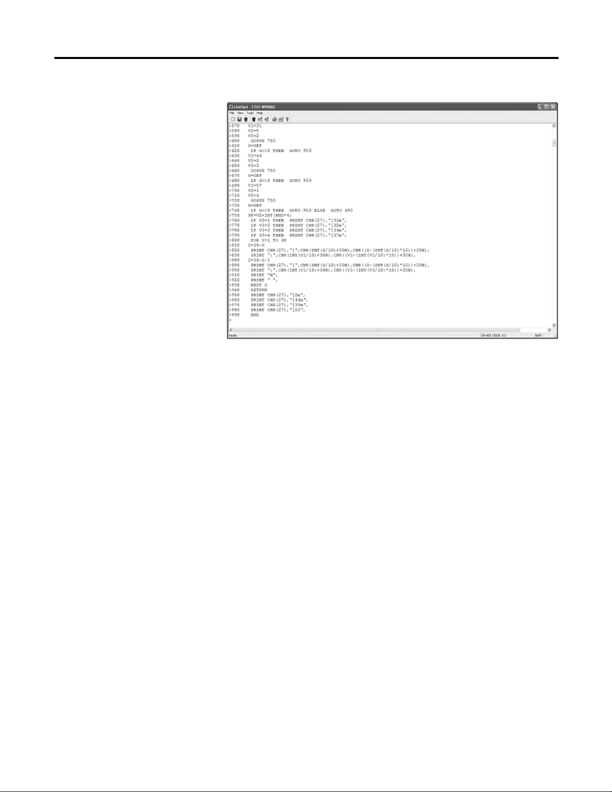
BASIC Interface Software Client Window
Installing the Software
The BASIC software is comprised of two CDs. They are:
• the 1747-WINBAS software CD.
• the optional RSLinx Classic OEM version software CD.
The 1747-WINBAS software enables communication to the 1747-BAS
module via an RS-232 serial port.
The RSLinx Classic OEM version software enables communication to
the 1747-BAS module via the DH-485 port.
To configure your computer serial port for communication with the
1747-BAS module, refer to
To configure your computer for communication with the 1747-BAS
module, refer to using DH-485 on
page 21.
page 22.
Install the 1747-WINBAS Software
To install the 1747-WINBAS software, insert the 1747-WINBAS
software CD into your CD drive and follow the installation
instructions.
Publication 1747-PM001A-EN-P - January 2007
Page 9

Installing Your BASIC Interface Software 7
Install the RSLinx Classic OEM Software
To install the RSLinx Classic OEM software (only necessary if
connecting to the BAS module using DH-485), insert the RSLinx
Classic OEM software CD into your CD drive and follow the
installation instructions.
Publication 1747-PM001A-EN-P - January 2007
Page 10

8 Installing Your BASIC Interface Software
Notes:
Publication 1747-PM001A-EN-P - January 2007
Page 11
Chapter
Getting Familiar With Your BASIC Interface
Software
This chapter is intended to give you an overview of the BASIC
Interface Software so you can understand the software’s general
structure.
2
Main Menu
File Menu
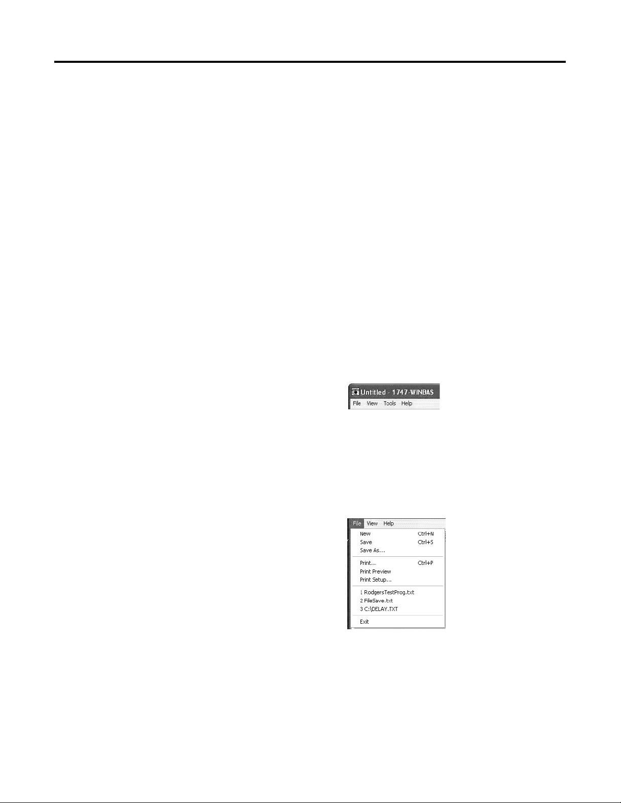
These menus are accessed through the Main menu:
• File
• View
• Tools
• Help
Main Menu
You can save and print programs from the File menu.
Saving and Printing Programs
From the File menu, you can choose the following options:
• File > New clears all the old data from the history buffer and the
dialog.
9 Publication 1747-PM001A-EN-P - January 2007
Page 12
10 Getting Familiar With Your BASIC Interface Software
Between File > Print Setup and File > Exit, there can be up to four file
names. These file names are a list of the most recent four files saved
using BASIC software. If you select one of these files, the title bar
document title will change to show the name of this file. Also, the
next time you save this data, the file name will be selected, but
nothing else will happen. No file is actually opened.
• File > Save saves the data to a file for later reference. This
command will also result in the new file name being displayed
in the title bar. The files are not appended. If you save the data
to the same file twice, the data that was first saved will be lost.
The data is saved as ASCII text exactly as it appears on the
BASIC software dialog.
• File > Save As saves the data to a file for later reference. This
command will also result in the new file name being displayed
in the title bar. The files are not appended. If you save the data
to the same file twice, the data that was first saved will be lost.
The data is saved as ASCII text exactly as it appears on the
BASIC software dialog.
• File > Print formats and sends the data to a printer.
• File > Print Preview lets you preview the printed data before
actually printing.
• File > Exit exits the BASIC software program.
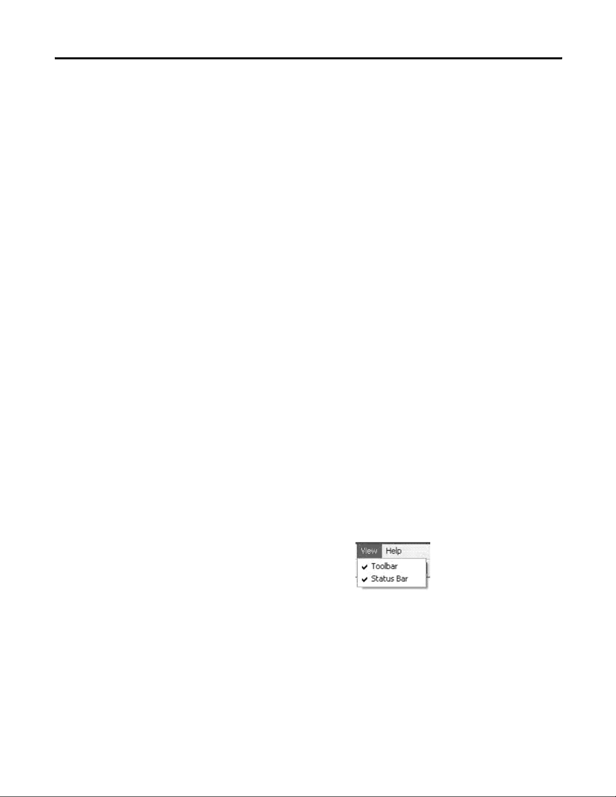
View Menu
The View menu lets you gain access to the toolbar and status bar.
Refer to page 20 for additional information on the toolbar and page 26
for additional information on the status bar.
Toolbar and Status Bar
From the View menu, you can choose the following options:
• View > Toolbar switches the toolbar on and off.
• View > Status Bar switches the status bar on and off.
Publication 1747-PM001A-EN-P - January 2007
Page 13

Getting Familiar With Your BASIC Interface Software 11
Tools Menu
The Tools menu lets you interface with your BASIC module.
Tools Menu
Cancel Xoff, Send Xon
From the Tools menu, you can choose the following options:
• Tools > Cancel Xoff clears an internal flag that indicates the
attached module has sent an Xoff to BASIC software. Only
choose Tools > Cancel Xoff on rare occasions. There are
situations when you are working with multiple BASIC modules.
One module may send an Xoff to BASIC software. You then
disconnect the cable from the first module and connect to
another module. BASIC software will appear to be locked up,
because it has received an Xoff and therefore should not be
transmitting any data. In this case, you can cancel the Xoff flag
via Tools > Cancel Xoff. There are also occasions when the
BASIC module may not transmit, because it thinks that it has
received an Xoff.
• Tools > Send Xon will immediately transmit an Xon to the
connected module.
Publication 1747-PM001A-EN-P - January 2007
Page 14

12 Getting Familiar With Your BASIC Interface Software
Debug
Tools > Debug opens a dialog that aids you in debugging the BASIC
program. The Variable Watch List box on the upper left side of the
dialog displays the variables you added. The buttons to the right of
the Variable Watch List box lets you add variables to the Watch List,
remove variables from the Watch List, get the latest values for the
variables in the Watch List and inspect strings in detail.
Debug Dialog
The following dialog lets you add a variable to the Variable Watch List.
Variable Added to the Debug Dialog
The following dialog shows the Debug Window with some variables
in the Watch List before clicking Update Data.
Variables in Watch List Before Update
Publication 1747-PM001A-EN-P - January 2007
Page 15

Getting Familiar With Your BASIC Interface Software 13
The following dialog shows the Debug Window with the same
variables after clicking Update Data.
Variables in Watch List After Update
It may be difficult to count the number of characters in the strings and
determine a character’s precise location in the string. This dialog
displays when you select a string in the Watch List Variable by clicking
Inspect String.
Inspect String Dialog
Below the Watch List box and to the left are two buttons that will put
the BASIC module in Single Step mode or clear Single Step mode. In
the module, Single-Step is enabled until it is disabled. When
Single-Step is enabled, clicking RUN causes the module to execute the
first line of the program and stop. Also, when Single-Step is enabled,
clicking CONT causes the module to execute the next line of BASIC
programming and stop.
Publication 1747-PM001A-EN-P - January 2007
Page 16

14 Getting Familiar With Your BASIC Interface Software
Below the Watch List box and in the middle are two buttons that
either set or clear a BASIC-program break point. The BASIC modules
allow only one break point to be set at a time. When this break point
is encountered during program execution, the program stops and the
BASIC module goes to the command prompt. Also, the break point is
automatically cleared by the module after it is encountered. If you
want to continuously stop inside a loop, the break point must be set
after each break. Clicking RUN causes the module to start executing
from the first line of the BASIC program. Clicking CONT causes the
module to continue executing the BASIC program after either a break
point or pressing Ctrl+C. If Ctrl+C detection is enabled in the module
(module default) and you press Ctrl+C, then the program will stop
executing at the end of the currently running line.
Below the Watch List box and to the right are three buttons that
provide short cuts for the RUN, CONT, and Ctrl+C BASIC commands.
Use these three buttons independently or in conjunction with
Single-Step or Break Point.
Click close at the bottom to close the Debug Window dialog.
Options
Tools > Options opens a dialog that lets you change the BASIC
software font size. The legal sizes are 12, 14, 16, 18, 20, 22, and 24.
List, List NUM
From the Tools menu, you can choose List and List NUM.
• Tools > List is a shortcut that sends the LIST command to the
BASIC module. The LIST command prints the entire program to
the BASIC software dialog.
• Tools > List NUM opens a dialog that lets you enter a line
number. Then the BASIC LIST command is sent to the module
followed by the line number (for example, LIST 100). This action
lists the BASIC program from the specified line number to the
end of the BASIC program to the BASIC software dialog.
Publication 1747-PM001A-EN-P - January 2007
Page 17

Getting Familiar With Your BASIC Interface Software 15
Line Number Dialog
• Tools > List NUM1-NUM2 opens a dialog that lets you enter the
first line number (NUM1). If a valid line number is entered, then
the same dialog is cleared for entry of the second line number
(NUM2). Then the BASIC LIST command is sent to the module
followed by both line numbers separated by a dash (for
example, LIST 100-200). This action lists the BASIC program
from the first specified line number to the second specified line
number to the BASIC software dialog.
RAM
Tools > Ram sends a RAM command to the BASIC module. The RAM
command causes the BASIC program pointer to be changed to point
at the program in RAM. In other words, the program in RAM is
selected.
ROM
From the Tools menu, you can choose the following options:
• Tools > Rom sends a ROM command to the BASIC module. The
ROM command causes the BASIC program pointer to be
changed to point at the first program in ROM (or ROM 1). In
other words, the ROM 1 program is selected.
• Tools > Rom N opens a dialog that lets you enter a number.
Then the BASIC ROM command is sent to the module followed
by the specified number (for example, ROM 3). This action
causes the BASIC program pointer to be changed to point at the
specified program in ROM.
ROM Number Dialog
Publication 1747-PM001A-EN-P - January 2007
Page 18

16 Getting Familiar With Your BASIC Interface Software
Xfer
Tools > Xfer sends a XFER command to the BASIC module. Use the
XFER command to transfer the currently selected program in ROM to
RAM and select RAM mode. After the XFER command executes, you
can edit the program in the same way you would edit any RAM
program.
Erase and Prog
From the Tools menu, you can choose the following options:
• Tools > Erase sends an ERASE command to the BASIC module.
The ERASE command deletes the last program stored in
EEPROM through the PROG command.
• Tools > Prog programs the resident EEPROM with the current
program in RAM.
• Tools > Prog1 programs the resident EEPROM with the port
information for all three ports, as well as MTOP information.
• Tools > Prog2 causes the first program stored in ROM (ROM 1)
to be run each time power is applied.
Hex Upload and Hex Download
From the Tools menu, you can choose the following options:
• Tools > Hex Upload opens a dialog that lets you enter/select a
file name (default extension .hex) and two numbers. These two
numbers are absolute microprocessor addresses. BASIC software
then sends the following command: PUSH ADDR1, ADDR2 :
CALL 101. The resulting data (in Intel Hex format) is saved to
the specified file.
Hex Upload Information Dialog
Publication 1747-PM001A-EN-P - January 2007
Page 19

Getting Familiar With Your BASIC Interface Software 17
• Tools > Hex Download opens a dialog that lets you enter/select
a file name (default extension .hex). BASIC software then sends
a CALL 100 command and downloads the specified Intel Hex file
to the module.
Hex Download Information Dialog
Module Backup and Restore
From the Tools menu, you can choose the following options:
• Tools > Module Backup opens a dialog that lets you enter a file
name. This file name (default extension .IMG) will be used to
store a backup of the entire module. This backup consists of
four or five files. The module type, module firmware release,
and other general information, as well as pointers to the other
files, are stored in the above .IMG file. The RAM information will
be stored in a file with the same above path and file name, but
with a .RAM extension. The port parameters and MTOP
information will be stored in a file with the same above path
and file name, but with a .PRM extension. The battery-backed
variable information will be stored in a file with the same above
path and file name, but with an .USR extension. If there is an
EEPROM present in the module, then ROM information will be
stored in a file with the same above path and file name, but with
a .ROM extension.
Backup/Restore Path and Filename Dialog
Publication 1747-PM001A-EN-P - January 2007
Page 20

18 Getting Familiar With Your BASIC Interface Software
Restore Dialog
• Tools > Module Restore opens a dialog that lets you enter a file
name (default extension.IMG). If the above file name is valid,
the module type matches, and the module firmware revision
matches, then the dialog lets you decide whether to restore the
battery backed variables. The file name is used to restore this
connected BASIC module exactly like the module used to
produce the original backup.
Publication 1747-PM001A-EN-P - January 2007
Page 21

Getting Familiar With Your BASIC Interface Software 19
Help Menu
The Help menu provides you with a resource to locate information
you need to keep your program operational.
From the Help menu, you can choose the following options:
• Help > About WINBAS will open as the dialog that identifies the
release and contact information.
About 1747-WINBAS Dialog
• Help > BAS Users Manual opens the SLC 500 BASIC and
BASIC-T Modules User Manual, publication 1746-UM004. Adobe
Acrobat software must be installed on the personal computer for
this function to work.
• Help > DB Users Manual opens the BASIC Module User Manual,
publication 1771-UM113. Adobe Acrobat software must be
installed on the personal computer for this function to work.
• Help > WINBAS Help opens this document. Adobe Acrobat
software must be installed on the personal computer for this
function to work.
Publication 1747-PM001A-EN-P - January 2007
Page 22

20 Getting Familiar With Your BASIC Interface Software
Standard Toolbar Icons
There are nine choices on the standard toolbar.
8
3
21
4 5
6
Icon Number Description
1 Performs the same function as File > New. It clears all the old data
from the history buffer and the screen.
2 Performs the same function as File > Save.
3 Transmits a RUN command followed by an ENTER out the serial port
to the attached BASIC module.
4 Sends a Crtl+C command out the serial port to the attached BASIC
module.
5 Downloads a BASIC program stored on disk to the attached BASIC
module. At the end of each downloaded line, the BASIC module will
tokenize the line then save it in memory. This tokenization process
takes time, which means the BASIC module input buffer can overflow
and data can be lost. If the program to be downloaded is more than a
few lines long (~10), then Xon/Xoff flow control is required on both
BASIC software and the BASIC module.
7
9
6 Uploads a BASIC program from the attached BASIC module and
stores the program in a file on the computer. The personal computer
saves the data to disk as it is being uploaded, which takes time. If the
program to be uploaded is longer that a few lines long, then Xon/Xoff
flow control is required on both BASIC software and the BASIC
module.
7 Performs the same function as File > Print.
8 Opens a dialog for you to configure the serial port.
9 Opens the About BASIC Interface Software dialog.
Publication 1747-PM001A-EN-P - January 2007
Page 23

Getting Familiar With Your BASIC Interface Software 21
Configure the Serial Port
Follow these steps to configure the serial port.
1. Click the hand-on-paper icon.
See icon number 8 on page 20.
The following dialog appears.
2. From each pull-down menu, choose a value for each parameter.
• Connection
• Bits per second
• Data bits
• Parity
• Stop bits
• Flow control
Publication 1747-PM001A-EN-P - January 2007
Page 24

22 Getting Familiar With Your BASIC Interface Software
Port Configuration Dialog Options
Parameter Value
Connect using
Bits per second 300, 1200, 2400, 4800, 9600, 19,200, 38,400, 57,600, or 115,200
Data bits 7 or 8
Parity None, even, or odd
Stop bits 1 or 2
Flow control None or Xon/Xoff
OK button • Saves the configuration.
Cancel button • Exits the configuration dialog returning you to the BASIC
X button • Exits the configuration dialog returning you to the BASIC
(1)
If you select DH-485, all other list boxes are disabled since the other parameters are not valid or set by RSLinx
software.
COM1, COM2, COM3, COM4, or DH-485
(1)
• Reconfigures the appropriate port.
• Exits the configuration dialog returning you to the BASIC
Interface main program.
Interface main program without saving any changes.
• Uses the previous configuration information to configure the
appropriate port.
Interface main program without saving.
• Uses the previous configuration information to configure the
appropriate port.
Publication 1747-PM001A-EN-P - January 2007
Configure DH-485
If you select DH-485 for the port and the BASIC software has never
made a connection via DH-485 previously, then the BASIC software
will open this dialog.
Select a Device
Page 25

Getting Familiar With Your BASIC Interface Software 23
Acceptable DH-485 interfaces are the 1784-PCMK, 1784-PKTX,
1784-PKTXD, or 1747-UIC convertor. Bridging to the DH-485 network
from other networks is not supported.
You must go through the selections shown in this dialog and
double-click the correct BASIC module.
BASIC Module Selection via RSWho Feature in RSLinx Classic Software
If you select DH-485 for the port and the BASIC software has
connected to a DH-485 BASIC module previously, then this dialog is
displayed. This dialog lets you select the previous connection path
without having to go through the RSLinx software selection process.
Last Connection Path Dialog
Publication 1747-PM001A-EN-P - January 2007
Page 26

24 Getting Familiar With Your BASIC Interface Software
User Window
The user window is the client area where the data received via the
port is displayed. There is a vertical scroll bar on the right side of the
window and a horizontal scroll bar on the bottom of the window. The
vertical scroll bar lets you view data that has scrolled off the viewable
page. The horizontal scroll bar lets you view data that exceeds the
width of the user window. Up to 128 characters can be displayed per
line. If more than 128 characters are received in one line, BASIC
software will automatically wrap the line to the next line.
You can view up to 1000 lines of data using BASIC software. If the
terminal emulator session exceeds more than 1000 lines, then the
oldest lines are discarded, while the newest 1000 lines are retained.
Pop-up Menu
If you click the right mouse while the mouse pointer is in the main
viewing window, this pop-up dialog is displayed.
Publication 1747-PM001A-EN-P - January 2007
• Right-clicking List performs the same function as Tools > List.
• Right-clicking List NUM performs the same function as Tools >
List NUM.
• Right-clicking List NUM1-NUM2 performs the same function as
Tools > List NUM1-NUM2.
• Right-clicking Edit Line causes BASIC software to evaluate where
the mouse is located at the time of the right-click.
• Right-clicking Cancel exits the pop-up dialog.
Page 27

Getting Familiar With Your BASIC Interface Software 25
Editing a BASIC Program
When you right-click Edit Line in the pop-up menu, the BASIC
software opens an edit dialog that lets you edit any BASIC line of
code. The edit box in this Edit Line dialog is automatically loaded with
the BASIC line being pointed at when you right-clicked the mouse.
You can modify this line in any fashion. If you clicked Enter Line, this
modified line will be downloaded to the BASIC module.
Edit Line Dialog
Publication 1747-PM001A-EN-P - January 2007
Page 28

26 Getting Familiar With Your BASIC Interface Software
Status Bar
The BASIC software status bar is at the very bottom of the user
window and is divided into five sections.
Button Description
User Help When you move the cursor over any menu item or the tool bar icon, a
description of the function or icon appears.
COM Port Status See COM Port Status section.
Caps Lock Provides capitalization status.
Num Lock Provides numbering status.
Scroll Lock Provides scroll status.
COM Port Status
COM Port Status has two functions. If you select a standard RS-232
COM port, the window contains the following information:
• Availability of the selected COM port
• Selected COM port
• Communication rate
• Parity
• Number of bits per character
• Number of stop bits
• Type of data flow control used (Xon/Xoff or None)
For example, COM1: 1200 N 8 1 None would indicate that the selected
COM port is COM1 and COM1 is configured for 1200 Kbps, no parity,
8 data bits per character, 1 stop bit, and no flow control. Or, X COM2:
19,200 E 7 2 Xon/Xoff would indicate COM2 was selected at 19,200
bps, with even parity, 7 data bits per character, 2 stop bits and
Xon/Xoff data flow control. However, the X in front of the string
indicates that COM2 is not available.
Publication 1747-PM001A-EN-P - January 2007
Page 29

Getting Familiar With Your BASIC Interface Software 27
If you select a DH-485 port, the following four pieces of information
are displayed:
• Availability of the BASIC software DH-485 connection
• DH-485
• RSLinx function return code
• DH-485 connection return code
For example, DH-485 0 0 indicates that the BASIC software is
connected to a BASIC module via the DH-485 network, and that there
are no problems. If a non-zero value is ever displayed for either the
RSLinx function return code or the DH-485 connection return code,
then the BASIC software has lost the connection to the BASIC module.
Further, X DH-485 0 0 indicates that the BASIC software was not able
to open a connection to a BASIC module.
Publication 1747-PM001A-EN-P - January 2007
Page 30

28 Getting Familiar With Your BASIC Interface Software
Notes:
Publication 1747-PM001A-EN-P - January 2007
Page 31

Keystroke Commands
Appendix
A
Keystroke Overview
Windows programs typically support several keystroke commands
that have been modified for use with BASIC Interface Software.
Keystroke Effect on BASIC Interface Software
Ctrl+C Transmits a Ctrl+C (O3h) command from the serial port.
Ctrl+N Transmits a Ctrl+N (OEh = ASCII S0 character) command from the
serial port.
Ctrl+O Transmits a Ctrl+O (OFh = ASCII SI character) command from the serial
port.
Ctrl+P Transmits a Ctrl+P (10h = ASCII DLE character) command from the
serial port.
Ctrl+S Transmits a Ctrl+S (13h = ASCII DC3 character) command from the
serial port.
Ctrl+V Transmits a Ctrl+V (16h = ASCII SYN character) command from the
serial port.
Ctrl+X Transmits a Ctrl+X (18h = ASCII ESC character) command from the
serial port.
Ctrl+Z Transmits a Ctrl+Z (1Ah = ASCII SUB character) command from the
serial port.
Esc Transmits an escape (1Bh = ASCII ESC character) command from the
serial port.
Backspace Transmits a DEL (7Fh = ASCII DEL character) command from the serial
port.
Delete Transmits a DEL (7Fh = ASCII DEL character) command from the serial
port.
Del Transmits a DEL (7Fh = ASCII DEL character) command from the serial
port.
F5 through F12 None.
Insert None.
Ins None.
Home Transmits an ESC [H command.
Page Up None.
Pg Up None.
Page Down None.
End Transmits an ESC [K command.
Up arrow Transmits an ESC [A command.
Down arrow Transmits an ESC [B command.
29 Publication 1747-PM001A-EN-P - January 2007
Page 32

30 Keystroke Commands
Keystroke Effect on BASIC Interface Software
Left arrow Transmits an ESC [D command.
Right arrow Transmits an ESC [C command.
F1 Transmits an ESC O P command.
F2 Transmits an ESC O Q command.
F3 Transmits an ESC O R command.
F4 Transmits an ESC O S command.
Publication 1747-PM001A-EN-P - January 2007
Page 33

Escape Sequences
Appendix
B
Escape Sequence Overview
Escape sequences are supported by BASIC Interface Software. The
fully-supported escape sequences are listed in this table.
Escape Sequence Description
ESC[#1;#2H Moves cursor to line 1 and column 2.
ESC[#1;#2f Moves cursor to line 1 and column 2.
ESC[#A Moves cursor up set number of lines.
ESC[#B Moves cursor down set number of lines.
ESC[#C Moves cursor forward set number of spaces.
ESC[#D Moves cursor back set number of spaces.
ESC[s Saves cursor position for recall later.
ESC[u Returns to saved cursor position.
ESC[2J Clears screen and homes cursor.
ESC[K Clears to end of line.
There are several escape sequences that are accepted, but no action is
taken. All of these no action sequences are of the form ESC[#m, where
# describes what display attributes are modified (for example,
ESC[45m means set the background color to magenta).
All other escape sequences display the string ESC in the dialog
followed by the actual sequence (for example, ESC[=h or ESC[=3;7h).
31 Publication 1747-PM001A-EN-P - January 2007
Page 34

32 Escape Sequences
Notes:
Publication 1747-PM001A-EN-P - January 2007
Page 35

Index
C
configure the serial port 21
conventions used in this manual 4
D
debug 12
E
edit a BASIC program 25
erase 16
escape sequences 31
F
file menu 9
H
help menu 19
hex download 16
hex upload 16
I
install the software 6
K
keystroke commands 29
L
list 14
list NUM 14
M
main menu
file menu 9
help menu 19
tools menu 11
view menu 10
module backup 17
module restore 17
O
options 14
overview
software 5
P
port status 26
print a program 9
prog 16
purpose of manual 3
R
RAM 15
related documentation 4
ROM 15
S
save a program 9
software
edit a program 25
installation 6
overview 5
print a program 9
save a program 9
status bar 26
T
tool bar 20
tools menu 11
U
user window 24
V
view menu 10
W
who should use this manual 3
X
Xfer 16
Xoff 11
Xon 11
Publication 1747-PM001A-EN-P - January 2007
Page 36

34 Index
Publication 1747-PM001A-EN-P - January 2007
Page 37

How Are We Doing?
Your comments on our technical publications will help us serve you better in the future.
Thank you for taking the time to provide us feedback.
You can complete this form and mail (or fax) it back to us or email us at
RADocumentComments@ra.rockwell.com
Pub. Title/Type BASIC Interface Software Programming Manual
Cat. No. 1747-WINBAS Pub. No. 1747-PM001A-EN-P Pub. Date January 2007 Part No. none
Please complete the sections below. Where applicable, rank the feature (1=needs improvement, 2=satisfactory, and 3=outstanding).
Overall Usefulness 1 2 3 How can we make this publication more useful for you?
Completeness
(all necessary information
is provided)
Technical Accuracy
(all provided information
(all provided information is
correct)
is
Clarity
easy to understand)
1 2 3 Can we add more information to help you?
procedure/step illustration feature
example guideline other
explanation definition
1 2 3 Can we be more accurate?
t ex t illustration
1 2 3 How can we make things clearer?
Other Comments You can add additional comments on the back of this form.
Your Name
Your Title/Function Would you like us to contact you regarding your comments?
Location/Phone ___No, there is no need to contact me
___Yes, please call me
___Yes, please email me at _______________________
___Yes, please contact me via _____________________
Return this form to: Rockwell Automation Technical Communications, 1 Allen-Bradley Dr., Mayfield Hts., OH 44124-9705
Fax: 440-646-3525 Email: RADocumentComments@ra.rockwell.com
Publication CIG-CO521C-EN-P- May 2003 PNnone957782-91
Page 38

Other Comments
PLEASE FASTEN HERE (DO NOT STAPLE)
PLEASE FOLD HERE
BUSINESS REPLY MAIL
FIRST-CLASS MAIL PERMIT NO. 18235 CLEVELAND OH
POSTAGE WILL BE PAID BY THE ADDRESSEE
NO POSTAGE
NECESSARY
IF MAILED
IN THE
UNITED STATES
PLEASE REMOVE
1 ALLEN-BRADLEY DR
MAYFIELD HEIGHTS OH 44124-9705
Page 39

Page 40

Rockwell Automation
Support
Rockwell Automation provides technical information on the Web to assist
you in using its products. At
find technical manuals, a knowledge base of FAQs, technical and application
notes, sample code and links to software service packs, and a MySupport
feature that you can customize to make the best use of these tools.
For an additional level of technical phone support for installation,
configuration, and troubleshooting, we offer TechConnect Support programs.
For more information, contact your local distributor or Rockwell Automation
representative, or visit
http://support.rockwellautomation.com, you can
http://support.rockwellautomation.com.
Installation Assistance
If you experience a problem with a hardware module within the first 24
hours of installation, please review the information that's contained in this
manual. You can also contact a special Customer Support number for initial
help in getting your module up and running.
United States 1.440.646.3223
Monday – Friday, 8am – 5pm EST
Outside United
States
Please contact your local Rockwell Automation representative for any
technical support issues.
New Product Satisfaction Return
Rockwell tests all of its products to ensure that they are fully operational
when shipped from the manufacturing facility. However, if your product is
not functioning, it may need to be returned.
United States Contact your distributor. You must provide a Customer Support case
number (see phone number above to obtain one) to your distributor in
order to complete the return process.
Outside United
States
Please contact your local Rockwell Automation representative for
return procedure.
Publication 1747-PM001A-EN-P - January 2007 39
Copyright © 2007 Rockwell Automation, Inc . All rights reserved. Printed in the U.S.A.
 Loading...