

Page 1

SMC Dialog Plus
Controller
Bulletin 150
3
20
19
172718
152516
14
30
29
28
26
24
23
112112
1
13
22
User Manual
5
Page 2
Please Read!
This manual is intended to guide qualified personnel in the
installation and operation of this product.
Because of the variety of uses for this equipment and because of the
differ ences between this soli d-sta te equipmen t and electromecha nical
equipment, the user of and those respo nsible for applying this
equipment must satisfy thems elves as to the acceptability of each
application an d use of the equipment. In no event will Al len -Bradley
Company, Inc. be respons ible or liable for indirect or consequential
damages resulting fro m the use or applica tion of this equipment.
The illustrations shown in this manual are intende d solely to ill ustra te
the text of this manual. Because of the many variables and
requirements assoc iated with any particular inst allation, the AllenBradley Company, Inc. cannot assume responsibi lity or liability for
actual use based on the illustrative uses and applications.
No patent liability is ass umed by Allen-Bradley Company, Inc. with
respect to use of informati on, circuits, or equipment described in this
text.
Reproduction of the content of this manual, in whole or in part,
without written permission of the Allen-Bradley Company, Inc. is
prohibited.
Important User Information
The information in this manual is organized in numbered chapters.
Read each chapter in sequence and perform procedur es when you are
instructed to do so. Do not pr oceed to the next chapter until you have
completed all procedure s.
Throughout this manual attention statements make you aware of
safety considerations:
ATTENTION: Identifies information about pra ctices
or circumstances that can lead to personal injury or
!
Attentions help you:
• Identify a hazard
• Avoid the hazard
• Recognize the consequenc es
Importa nt: Identif ies information that is especially important for
SMC Dialog Plus, SMB, SCANport, and Accu-Stop are trademarks of Rockwell Automation.
DeviceNet is a trademark of the Open DeviceNet Vendors Association (O.D.V.A.)
death, property damage, or economi c loss .
successful applic ation and underst anding of thi s product.
For Bulletin 150 SMC Smart Motor Controller technical support on start-up or existing
installations, contact your Allen-Bradley representative. In the United States and Canada, you
can also call 1-800-765-SMCS (765-7627) for assistance Monday through Friday from 8:00
a.m. to 12:00 noon and 1:00 p.m. to 4:30 p.m. (central time zone). Areas outside the United
States and Canada can call 001-414-382-4650 for assistance.
Page 3

Table of Contents
Chapter 1 Product Overview 1-1
Description . . . . . . . . . . . . . . . . . . . . . . . . . . . . . . . . . . . . . . . . 1-1
Operation . . . . . . . . . . . . . . . . . . . . . . . . . . . . . . . . . . . . . . . . . . 1-1
Starting Modes . . . . . . . . . . . . . . . . . . . . . . . . . . . . . . . . . . . . . 1-2
Soft Start . . . . . . . . . . . . . . . . . . . . . . . . . . . . . . . . . . . . . . . . 1-2
Selectable Kickstart . . . . . . . . . . . . . . . . . . . . . . . . . . . . . . . . 1-3
Current Limit Start. . . . . . . . . . . . . . . . . . . . . . . . . . . . . . . . . . 1-3
Dual Ramp Start . . . . . . . . . . . . . . . . . . . . . . . . . . . . . . . . . . . 1-4
Full Voltage Start . . . . . . . . . . . . . . . . . . . . . . . . . . . . . . . . . . 1-4
Energy Saver . . . . . . . . . . . . . . . . . . . . . . . . . . . . . . . . . . . . . . . 1-5
Phase Rebalance . . . . . . . . . . . . . . . . . . . . . . . . . . . . . . . . . . . . 1-5
Protection and Diagnostics . . . . . . . . . . . . . . . . . . . . . . . . . . . . . 1-5
Overload . . . . . . . . . . . . . . . . . . . . . . . . . . . . . . . . . . . . . . . . 1-5
Stall Protection and Jam Detection . . . . . . . . . . . . . . . . . . . . . 1-8
Open Gate . . . . . . . . . . . . . . . . . . . . . . . . . . . . . . . . . . . . . . . 1-9
Line Faults . . . . . . . . . . . . . . . . . . . . . . . . . . . . . . . . . . . . . . . 1-9
Underload . . . . . . . . . . . . . . . . . . . . . . . . . . . . . . . . . . . . . . . 1-9
Excessive Starts/Hour . . . . . . . . . . . . . . . . . . . . . . . . . . . . . 1-10
Overtemperature . . . . . . . . . . . . . . . . . . . . . . . . . . . . . . . . . 1-10
Metering . . . . . . . . . . . . . . . . . . . . . . . . . . . . . . . . . . . . . . . . . 1-10
Communication . . . . . . . . . . . . . . . . . . . . . . . . . . . . . . . . . . . . 1-11
Programming . . . . . . . . . . . . . . . . . . . . . . . . . . . . . . . . . . . . . . 1-11
Status Indication . . . . . . . . . . . . . . . . . . . . . . . . . . . . . . . . . . . 1-11
Control Options . . . . . . . . . . . . . . . . . . . . . . . . . . . . . . . . . . . . . 1-12
Soft Stop Option . . . . . . . . . . . . . . . . . . . . . . . . . . . . . . . . . . 1-12
Pump Control Option . . . . . . . . . . . . . . . . . . . . . . . . . . . . . . 1-13
Preset Slow Speed Option . . . . . . . . . . . . . . . . . . . . . . . . . . 1-13
SMB‰ Smart Motor Braking Option . . . . . . . . . . . . . . . . . . 1-14
Accu-Stop‰ Option . . . . . . . . . . . . . . . . . . . . . . . . . . . . . . . 1-15
Slow Speed with Braking Option . . . . . . . . . . . . . . . . . . . . . 1-15
Chapter 2 Installation
Receiving . . . . . . . . . . . . . . . . . . . . . . . . . . . . . . . . . . . . . . . . . . 2-1
Unpacking . . . . . . . . . . . . . . . . . . . . . . . . . . . . . . . . . . . . . . . . . 2-1
Inspecting. . . . . . . . . . . . . . . . . . . . . . . . . . . . . . . . . . . . . . . . . . 2-1
Storing . . . . . . . . . . . . . . . . . . . . . . . . . . . . . . . . . . . . . . . . . . . . 2-1
General Precautions . . . . . . . . . . . . . . . . . . . . . . . . . . . . . . . . . . 2-2
Heat Dissipation . . . . . . . . . . . . . . . . . . . . . . . . . . . . . . . . . . . . . 2-2
Enclosures . . . . . . . . . . . . . . . . . . . . . . . . . . . . . . . . . . . . . . . . . 2-2
Ventilated Enclosures . . . . . . . . . . . . . . . . . . . . . . . . . . . . . . . 2-3
Non-ventilated Enclosures . . . . . . . . . . . . . . . . . . . . . . . . . . . 2-3
Mounting . . . . . . . . . . . . . . . . . . . . . . . . . . . . . . . . . . . . . . . . . . 2-4
Page 4

toc–iv
Table of Contents
Dimensions . . . . . . . . . . . . . . . . . . . . . . . . . . . . . . . . . . . . . . 2-4
Power Factor Correction Capacitors . . . . . . . . . . . . . . . . . . . . . . 2-9
Fast Acting Current-limiting Fuses . . . . . . . . . . . . . . . . . . . . . . 2-10
Protective Modules . . . . . . . . . . . . . . . . . . . . . . . . . . . . . . . . . . 2-11
Motor Overload Protection. . . . . . . . . . . . . . . . . . . . . . . . . . . . . 2-11
Bypass . . . . . . . . . . . . . . . . . . . . . . . . . . . . . . . . . . . . . . . . . 2-11
Two-speed Motors . . . . . . . . . . . . . . . . . . . . . . . . . . . . . . . . 2-11
Multi-motor Protection . . . . . . . . . . . . . . . . . . . . . . . . . . . . . 2-11
Human Interface Module . . . . . . . . . . . . . . . . . . . . . . . . . . . . . 2-12
Connecting the Human Interface Module to the Controller . . . 2-13
Control Enable . . . . . . . . . . . . . . . . . . . . . . . . . . . . . . . . . . . 2-13
Communication Modules . . . . . . . . . . . . . . . . . . . . . . . . . . . . . 2-16
Converter Modules . . . . . . . . . . . . . . . . . . . . . . . . . . . . . . . . . . 2-16
Electromagnetic Compatibility (EMC) . . . . . . . . . . . . . . . . . . . . 2-18
Enclosure . . . . . . . . . . . . . . . . . . . . . . . . . . . . . . . . . . . . . . . 2-18
Grounding . . . . . . . . . . . . . . . . . . . . . . . . . . . . . . . . . . . . . . 2-18
Wiring . . . . . . . . . . . . . . . . . . . . . . . . . . . . . . . . . . . . . . . . . 2-19
Accessory Requirements . . . . . . . . . . . . . . . . . . . . . . . . . . . 2-19
Chapter 3 Wiring
Chapter 4 Programming
Terminal Locations . . . . . . . . . . . . . . . . . . . . . . . . . . . . . . . . . . . 3-1
Power Wiring. . . . . . . . . . . . . . . . . . . . . . . . . . . . . . . . . . . . . . 3-3
Control Power . . . . . . . . . . . . . . . . . . . . . . . . . . . . . . . . . . . . . . 3-4
Control Voltage . . . . . . . . . . . . . . . . . . . . . . . . . . . . . . . . . . . . 3-4
Control Wiring . . . . . . . . . . . . . . . . . . . . . . . . . . . . . . . . . . . . 3-4
Fan Power. . . . . . . . . . . . . . . . . . . . . . . . . . . . . . . . . . . . . . . . . . 3-5
Fan Terminations . . . . . . . . . . . . . . . . . . . . . . . . . . . . . . . . . . . 3-5
Control Terminal Designations . . . . . . . . . . . . . . . . . . . . . . . . . . 3-6
Grounding Provision . . . . . . . . . . . . . . . . . . . . . . . . . . . . . . . . . . 3-6
Standard Controller Wiring Diagrams . . . . . . . . . . . . . . . . . . . . . 3-7
Overview . . . . . . . . . . . . . . . . . . . . . . . . . . . . . . . . . . . . . . . . . . 4-1
Keypad Description . . . . . . . . . . . . . . . . . . . . . . . . . . . . . . . . . . 4-1
Programming Menu . . . . . . . . . . . . . . . . . . . . . . . . . . . . . . . . . . 4-1
Password . . . . . . . . . . . . . . . . . . . . . . . . . . . . . . . . . . . . . . . . . . 4-5
Search . . . . . . . . . . . . . . . . . . . . . . . . . . . . . . . . . . . . . . . . . . . . 4-5
Parameter Management . . . . . . . . . . . . . . . . . . . . . . . . . . . . . . . 4-6
Random Access Memory (RAM). . . . . . . . . . . . . . . . . . . . . . . . 4-6
Read-only Memory (ROM) . . . . . . . . . . . . . . . . . . . . . . . . . . . 4-6
Electrically Erasable Programmable
Read-only Memory (EEPROM) . . . . . . . . . . . . . . . . . . . . . . 4-6
Using Parameter Management . . . . . . . . . . . . . . . . . . . . . . . . 4-7
Parameter Modification . . . . . . . . . . . . . . . . . . . . . . . . . . . . . . . 4-8
Soft Start. . . . . . . . . . . . . . . . . . . . . . . . . . . . . . . . . . . . . . . . . . . 4-9
Current Limit Start . . . . . . . . . . . . . . . . . . . . . . . . . . . . . . . . . . . 4-9
Dual Ramp Start . . . . . . . . . . . . . . . . . . . . . . . . . . . . . . . . . . . . 4-10
Full Voltage Start . . . . . . . . . . . . . . . . . . . . . . . . . . . . . . . . . . . 4-10
Basic Setup . . . . . . . . . . . . . . . . . . . . . . . . . . . . . . . . . . . . . . . 4-11
Advanced Setup . . . . . . . . . . . . . . . . . . . . . . . . . . . . . . . . . . . . 4-12
Page 5

Table of Contents
toc–v
Example Settings . . . . . . . . . . . . . . . . . . . . . . . . . . . . . . . . . . . 4-13
Undervoltage . . . . . . . . . . . . . . . . . . . . . . . . . . . . . . . . . . . . . 4-13
Overvoltage . . . . . . . . . . . . . . . . . . . . . . . . . . . . . . . . . . . . . . 4-13
Jam. . . . . . . . . . . . . . . . . . . . . . . . . . . . . . . . . . . . . . . . . . . . 4-13
Underload . . . . . . . . . . . . . . . . . . . . . . . . . . . . . . . . . . . . . . . 4-13
Chapter 5 Calibration
Chapter 6 Metering
Chapter 7 Options
Chapter 8 Serial Communications
Overview . . . . . . . . . . . . . . . . . . . . . . . . . . . . . . . . . . . . . . . . . . 5-1
Motor Data Entry . . . . . . . . . . . . . . . . . . . . . . . . . . . . . . . . . . . . 5-1
Calibration Procedure . . . . . . . . . . . . . . . . . . . . . . . . . . . . . . . . . 5-3
Overview. . . . . . . . . . . . . . . . . . . . . . . . . . . . . . . . . . . . . . . . . . . 6-1
Viewing Metering Data . . . . . . . . . . . . . . . . . . . . . . . . . . . . . . . . 6-1
Overview . . . . . . . . . . . . . . . . . . . . . . . . . . . . . . . . . . . . . . . . . . 7-1
Human Interface Module . . . . . . . . . . . . . . . . . . . . . . . . . . . . . . 7-1
Programming Parameters . . . . . . . . . . . . . . . . . . . . . . . . . . . . . 7-3
Control Wiring for SCANport Control . . . . . . . . . . . . . . . . . . . . . . 7-5
Soft Stop, Pump Control, and
SMB Smart Motor Braking Options . . . . . . . . . . . . . . . . . . . . . . . 7-6
Soft Stop Option . . . . . . . . . . . . . . . . . . . . . . . . . . . . . . . . . . . . 7-12
Pump Control Option . . . . . . . . . . . . . . . . . . . . . . . . . . . . . . . . . 7-13
SMB Smart Motor Braking Option . . . . . . . . . . . . . . . . . . . . . . . 7-14
Preset Slow Speed and Accu-Stop Options . . . . . . . . . . . . . . . . 7-15
Preset Slow Speed Option . . . . . . . . . . . . . . . . . . . . . . . . . . . . 7-20
Accu-Stop Option . . . . . . . . . . . . . . . . . . . . . . . . . . . . . . . . . . . 7-21
Slow Speed with Braking Option . . . . . . . . . . . . . . . . . . . . . . . . 7-22
Overview . . . . . . . . . . . . . . . . . . . . . . . . . . . . . . . . . . . . . . . . . . 8-1
Logic Control Data . . . . . . . . . . . . . . . . . . . . . . . . . . . . . . . . . . . 8-1
Control Wiring . . . . . . . . . . . . . . . . . . . . . . . . . . . . . . . . . . . . . . 8-1
Control Enable . . . . . . . . . . . . . . . . . . . . . . . . . . . . . . . . . . . . . . 8-2
SMC Status Data . . . . . . . . . . . . . . . . . . . . . . . . . . . . . . . . . . . . 8-3
Reference/Feedback . . . . . . . . . . . . . . . . . . . . . . . . . . . . . . . . . 8-3
Parameter Listing . . . . . . . . . . . . . . . . . . . . . . . . . . . . . . . . . . . . 8-3
Scale Factor Conversion . . . . . . . . . . . . . . . . . . . . . . . . . . . . . . . 8-3
Display Unit Equivalents . . . . . . . . . . . . . . . . . . . . . . . . . . . . . . . 8-4
Datalinks . . . . . . . . . . . . . . . . . . . . . . . . . . . . . . . . . . . . . . . . . . 8-4
Interfacing . . . . . . . . . . . . . . . . . . . . . . . . . . . . . . . . . . . . . . . . . 8-4
Processing Time . . . . . . . . . . . . . . . . . . . . . . . . . . . . . . . . . . . . . 8-4
Remote I/O Examples . . . . . . . . . . . . . . . . . . . . . . . . . . . . . . . . . 8-5
Example #1 – SLC 500 Controller without Block Transfer . . . . 8-5
1203-GD1 Communication Module Switch Settings . . . . . . . . 8-6
G File Configuration . . . . . . . . . . . . . . . . . . . . . . . . . . . . . . . . . 8-7
I/O Addressing . . . . . . . . . . . . . . . . . . . . . . . . . . . . . . . . . . . . 8-7
Example #1 - Ladder Logic Program . . . . . . . . . . . . . . . . . . . . 8-9
Example #2 - SLC 500 Controller with Block Transfer . . . . . . 8-10
1203-GD1 Communication Module Switch Settings . . . . . . . 8-10
Example #2 – Ladder Logic Program . . . . . . . . . . . . . . . . . . 8-15
Page 6

toc–vi
Table of Contents
Example #3 – PLC 5/20, 5/40, 5/60, and 5/80 . . . . . . . . . . . 8-18
1203-GD1 Communication Module Switch Settings . . . . . . . 8-19
I/O Addressing . . . . . . . . . . . . . . . . . . . . . . . . . . . . . . . . . . . 8-19
Block Transfer Instructions . . . . . . . . . . . . . . . . . . . . . . . . . . 8-21
Block Transfer Datafiles . . . . . . . . . . . . . . . . . . . . . . . . . . . . 8-22
Example #3 Ladder Logic Program . . . . . . . . . . . . . . . . . . . . 8-23
DeviceNet Examples . . . . . . . . . . . . . . . . . . . . . . . . . . . . . . . . . 8-24
Example #1 SLC Controller with Explicit Messaging. . . . . . . . 8-24
1203-GK5 Communication Module Switch Settings . . . . . . . . 8-24
Example Information . . . . . . . . . . . . . . . . . . . . . . . . . . . . . . . 8-25
Switch Settings . . . . . . . . . . . . . . . . . . . . . . . . . . . . . . . . . . . 8-25
I/O Mapping . . . . . . . . . . . . . . . . . . . . . . . . . . . . . . . . . . . . . 8-25
SMC Dialog Plus Controller Logic Command Addresses . . . . . 8-29
Explicit Messaging. . . . . . . . . . . . . . . . . . . . . . . . . . . . . . . . . 8-29
Explicit Message Request (Get Attribute Multiple) . . . . . . . . . 8-29
Explicit Message Response (Get Attribute Multiple) . . . . . . . . 8-29
Examples . . . . . . . . . . . . . . . . . . . . . . . . . . . . . . . . . . . . . . . 8-30
Sequence of Events . . . . . . . . . . . . . . . . . . . . . . . . . . . . . . . . 8-31
Setting up the Data File . . . . . . . . . . . . . . . . . . . . . . . . . . . . . 8-31
Example Ladder Logic Program . . . . . . . . . . . . . . . . . . . . . . . 8-32
Chapter 9 Diagnostics
Overview . . . . . . . . . . . . . . . . . . . . . . . . . . . . . . . . . . . . . . . . . . 9-1
Protection Programming . . . . . . . . . . . . . . . . . . . . . . . . . . . . . 9-1
Fault Display . . . . . . . . . . . . . . . . . . . . . . . . . . . . . . . . . . . . . . . 9-1
Clear Fault . . . . . . . . . . . . . . . . . . . . . . . . . . . . . . . . . . . . . . . . . 9-1
Fault Buffer . . . . . . . . . . . . . . . . . . . . . . . . . . . . . . . . . . . . . . . . . 9-2
Fault Codes . . . . . . . . . . . . . . . . . . . . . . . . . . . . . . . . . . . . . . 9-2
Fault Auxiliary Contact . . . . . . . . . . . . . . . . . . . . . . . . . . . . . . . . 9-2
Fault Definitions . . . . . . . . . . . . . . . . . . . . . . . . . . . . . . . . . . . . . 9-3
Power Loss . . . . . . . . . . . . . . . . . . . . . . . . . . . . . . . . . . . . . . . 9-3
Line Fault . . . . . . . . . . . . . . . . . . . . . . . . . . . . . . . . . . . . . . . . 9-3
Phase Reversal . . . . . . . . . . . . . . . . . . . . . . . . . . . . . . . . . . . . . . 9-3
Overvoltage and Undervoltage Protection . . . . . . . . . . . . . . . . 9-3
Voltage Unbalance. . . . . . . . . . . . . . . . . . . . . . . . . . . . . . . . . . 9-4
Stall Protection . . . . . . . . . . . . . . . . . . . . . . . . . . . . . . . . . . . . 9-4
Jam Detection . . . . . . . . . . . . . . . . . . . . . . . . . . . . . . . . . . . . . 9-4
Overload Protection . . . . . . . . . . . . . . . . . . . . . . . . . . . . . . . . . 9-4
Underload . . . . . . . . . . . . . . . . . . . . . . . . . . . . . . . . . . . . . . . . 9-4
Open Gate . . . . . . . . . . . . . . . . . . . . . . . . . . . . . . . . . . . . . . . . 9-5
Excess Starts/Hour . . . . . . . . . . . . . . . . . . . . . . . . . . . . . . . . . 9-5
Controller Temp. . . . . . . . . . . . . . . . . . . . . . . . . . . . . . . . . . . . 9-5
Comm Fault . . . . . . . . . . . . . . . . . . . . . . . . . . . . . . . . . . . . . . 9-5
Chapter 10 Troubleshooting
Introduction. . . . . . . . . . . . . . . . . . . . . . . . . . . . . . . . . . . . . . . . 10-1
Control Module Removal . . . . . . . . . . . . . . . . . . . . . . . . . . . . . . 10-6
24–135 Amp . . . . . . . . . . . . . . . . . . . . . . . . . . . . . . . . . . . . 10-7
Page 7

180–360 Amp . . . . . . . . . . . . . . . . . . . . . . . . . . . . . . . . . . . 10-8
500–1000 Amp . . . . . . . . . . . . . . . . . . . . . . . . . . . . . . . . . . 10-10
Control Module Replacement . . . . . . . . . . . . . . . . . . . . . . . . . 10-11
Protective Cover Removal . . . . . . . . . . . . . . . . . . . . . . . . . . . . 10-12
650–1000 Amp . . . . . . . . . . . . . . . . . . . . . . . . . . . . . . . . . 10-12
MOV Fuse Replacement . . . . . . . . . . . . . . . . . . . . . . . . . . . . . 10-13
500–1000 Amp . . . . . . . . . . . . . . . . . . . . . . . . . . . . . . . . . 10-13
Power Module and Interface Board Resistance Check . . . . . . 10-13
24–135 Amp . . . . . . . . . . . . . . . . . . . . . . . . . . . . . . . . . . . 10-14
180-1000 Amp . . . . . . . . . . . . . . . . . . . . . . . . . . . . . . . . . . 10-23
Appendix A Specifications
Appendix B Parameter Information
Appendix C Renewal Parts
Appendix D Accessories
Table of Contents
toc–vii
Figures
Figure 1.1 Soft Start . . . . . . . . . . . . . . . . . . . . . . . . . . . . . . . . 1-2
Figure 1.2 Selectable Kickstart . . . . . . . . . . . . . . . . . . . . . . . 1-3
Figure 1.3 Current Limit Start . . . . . . . . . . . . . . . . . . . . . . . . 1-3
Figure 1.4 Dual Ramp Start . . . . . . . . . . . . . . . . . . . . . . . . . . 1-4
Figure 1.5 Full Voltage Start . . . . . . . . . . . . . . . . . . . . . . . . . . 1-4
Figure 1.6 Overload Trip Curves . . . . . . . . . . . . . . . . . . . . . . . 1-7
Figure 1.7 Restart Trip Curves after Auto Reset. . . . . . . . . . . . 1-7
Figure 1.8 Stall Protection . . . . . . . . . . . . . . . . . . . . . . . . . . . 1-8
Figure 1.9 Jam Detection . . . . . . . . . . . . . . . . . . . . . . . . . . . . 1-8
Figure 1.10 ScanPort Location . . . . . . . . . . . . . . . . . . . . . . . . 1-11
Figure 1.11 Built-in Keypad and LCD . . . . . . . . . . . . . . . . . . . 1-11
Figure 1.12 Soft Stop Option . . . . . . . . . . . . . . . . . . . . . . . . . 1-12
Figure 1.13 Pump Control Option . . . . . . . . . . . . . . . . . . . . . . 1-13
Figure 1.14 Preset Slow Speed Option . . . . . . . . . . . . . . . . . . 1-13
Figure 1.15 SMB Smart Motor Braking Option. . . . . . . . . . . . . 1-14
Figure 1.16 Accu-Stop Option . . . . . . . . . . . . . . . . . . . . . . . . 1-15
Figure 1.17 Slow Speed with Braking Option . . . . . . . . . . . . . 1-15
Figure 2.1 Dimensions: 24, 35, and 54 Amp Controllers . . . . 2-4
Figure 2.2 Dimensions: 97 and 135 Amp Controllers . . . . . . . 2-5
Figure 2.3 Dimensions: 180 through 360 Amp Controllers . . . 2-6
Figure 2.4 Dimensions: 500 Amp Controller . . . . . . . . . . . . . . 2-7
Figure 2.5 Dimensions: 650-1000 Amp Controllers . . . . . . . . 2-8
Figure 2.6 Typical Wiring Diagram for Power
Factor Correction Capacitors . . . . . . . . . . . . . . . . . 2-9
Figure 2.7 SMC Dialog Plus Controller with
Human Interface Module . . . . . . . . . . . . . . . . . . . 2-13
Figure 2.8 SMC Dialog Plus Controller with
Communication Module . . . . . . . . . . . . . . . . . . . . 2-16
Figure 2.9 Converter Module Connection Interface . . . . . . . . 2-17
Page 8

toc–viii
Table of Contents
Figure 2.10 Current Transformer Connection
to Converter Module . . . . . . . . . . . . . . . . . . . . . . 2-18
Figure 3.1 Wiring Terminal Locations (24 to 54 Amp) . . . . . . . 3-1
Figure 3.2 Wiring Terminal Locations (97 and 135 Amp) . . . . 3-1
Figure 3.3 Wiring Terminal Locations (180 to 360 Amp) . . . . . 3-2
Figure 3.4 Wiring Terminal Locations (500 Amp). . . . . . . . . . . 3-2
Figure 3.5 Wiring Terminal Locations (650 to 1000 Amp) . . . . 3-3
FIgure 3.6 97A and 135A Fan Terminations . . . . . . . . . . . . . . 3-5
Figure 3.7 180A to 500A Fan Terminations . . . . . . . . . . . . . . . 3-5
Figure 3.8 650A to 1000A Fan Terminations . . . . . . . . . . . . . . 3-5
Figure 3.9 SMC Dialog Plus Controller Control Terminals . . . . 3-6
Figure 3.10 Grounding Provision . . . . . . . . . . . . . . . . . . . . . . . 3-6
Figure 3.11 Typical Wiring Diagram for Standard Controller . . . 3-7
Figure 3.12 Typical Wiring Diagram for Two-Wire Control or
Programmable Control Interfacing . . . . . . . . . . . . . 3-8
Figure 3.13 Typical Wiring Diagram for
Dual Ramp Applications . . . . . . . . . . . . . . . . . . . . 3-9
Figure 3.14 Typical Wiring Diagram for Start-Stop
Control via the SCANport . . . . . . . . . . . . . . . . . . . 3-10
Figure 3.15 Typical Wiring Diagram for
Retrofit Applications. . . . . . . . . . . . . . . . . . . . . . . 3-11
Figure 3.16 Typical Wiring Diagram for
Isolation Applications . . . . . . . . . . . . . . . . . . . . . 3-12
Figure 3.17 Typical Wiring Diagram for
Bypass Applications . . . . . . . . . . . . . . . . . . . . . . 3-13
Figure 3.18 Typical Wiring Diagram for Bypass
with Isolation Applications . . . . . . . . . . . . . . . . . . 3-14
Figure 3.19 Typical Wiring Diagram for
Shunt Trip Applications . . . . . . . . . . . . . . . . . . . . 3-15
Figure 3.20 Typical Wiring Diagram for Single
Speed Reversing Applications . . . . . . . . . . . . . . . 3-16
Figure 3.21 Typical Wiring Diagram for
Two-speed Applications . . . . . . . . . . . . . . . . . . . 3-17
Figure 3.22 Typical Wiring Diagram for
Hand-Off-Auto (SCANport) Control . . . . . . . . . . . . 3-18
Figure 4.1 Menu Structure Hierarchy . . . . . . . . . . . . . . . . . . . 4-2
Figure 4.2 Memory Block Diagram . . . . . . . . . . . . . . . . . . . . . 4-6
Figure 7-1 Typical Wiring Diagram . . . . . . . . . . . . . . . . . . . . . 7-6
Figure 7.2 Typical Retrofit Wiring Diagram . . . . . . . . . . . . . . . 7-7
Figure 7.3 Typical Wiring Diagram for Applications
Requiring an Isolation Contactor . . . . . . . . . . . . . . 7-8
Figure 7.4 Typical Wiring Diagram for Applications
Requiring a Bypass Contactor . . . . . . . . . . . . . . . . 7-9
Figure 7.5 Typical Wiring Diagram for Two-wire Control
or Programmable Controller Interfacing . . . . . . . . 7-10
Figure 7.6 Typical Wiring Diagram for
Hand-Off-Auto (SCANport) Control . . . . . . . . . . . . 7-11
Figure 7.7 Soft Stop Option Sequence of Operation . . . . . . . 7-12
Figure 7.8 Pump Control Option Sequence of Operation . . . . 7-13
Page 9

Table of Contents
toc–ix
Figure 7.9 SMB Smart Motor Braking Sequence
of Operation 7-14
Figure 7.10 Typical Wiring Diagram for the
Preset Slow Speed Option . . . . . . . . . . . . . . . . . . 7-15
Figure 7.11 Typical Retrofit Wiring Diagram . . . . . . . . . . . . . . 7-16
Figure 7.12 Typical Wiring Diagram for Applications
Requiring an Isolation Contactor . . . . . . . . . . . . . 7-17
Figure 7.13 Typical Wiring Diagram for Applications
Requiring a Bypass Contactor . . . . . . . . . . . . . . . 7-18
Figure 7.14 Typical Wiring Diagram for
Hand-Off-Auto (SCANport) Control . . . . . . . . . . . . 7-19
Figure 7.15 Preset Slow Speed Option
Sequence of Operation . . . . . . . . . . . . . . . . . . . . 7-20
Figure 7.16 Accu-Stop Option Sequence of Operation . . . . . . 7-21
Figure 7.17 Typical Wiring Diagram for the
Slow Speed with Braking Option . . . . . . . . . . . . . 7-22
Figure 7.18 Typical Retrofit Wiring Diagram for the
Slow Speed with Braking Option . . . . . . . . . . . . . 7-23
Figure 7.19 Typical Wiring Diagram for the Slow Speed
with Braking Option with an Isolation Contactor . . 7-24
Figure 7.20 Typical Wiring Diagram for the Slow Speed
with Braking Option with a Bypass Contactor . . . . 7-25
Figure 7.21 Slow Speed with Braking Option Sequence
of Operation . . . . . . . . . . . . . . . . . . . . . . . . . . . . 7-26
Figure 9.1 Fault Display . . . . . . . . . . . . . . . . . . . . . . . . . . . . . 9-1
Figure 10.1 Troubleshooting Flowchart. . . . . . . . . . . . . . . . . . 10-2
Figure 10.2 Removal of Control Module (24–135A) . . . . . . . . 10-7
Figure 10.3 Removal of Control Module (180–360A) . . . . . . . 10-9
Figure 10.4 Removal of Protective Cover (500–1000A) . . . . 10-12
Figure 10.5 Removal of Control Module (500–1000A) . . . . . 10-10
Figure 10.6 MOV Fuse Replacement . . . . . . . . . . . . . . . . . . 10-13
Figure 10.7 Pin Locations for Power Module
Resistance Check . . . . . . . . . . . . . . . . . . . . . . . 10-22
Figure 10.8 Pin Locations for Power Pole Resistance
Check (180–1000A) . . . . . . . . . . . . . . . . . . . . . 10-24
Figure 10.9 Gate and Thermistor Lead Identification
(180–1000A) . . . . . . . . . . . . . . . . . . . . . . . . . . . 10-25
Tables
Table 2.A Maximum Heat Dissipation. . . . . . . . . . . . . . . . . . . 2-2
Table 2.B Minimum Ventilation Openings . . . . . . . . . . . . . . . 2-3
Table 2.C Recommended Fuses . . . . . . . . . . . . . . . . . . . . . 2-10
Table 2.D Converter Module Selection Guide . . . . . . . . . . . . 2-16
Table 3.A Lug Wire Capacity . . . . . . . . . . . . . . . . . . . . . . . . . 3-3
Table 3.B Tightening Torque . . . . . . . . . . . . . . . . . . . . . . . . . 3-3
Table 3.C Lug Wire Capacity and Tightening Torque . . . . . . . 3-4
Table 3.D Heatsink Fan Control Power . . . . . . . . . . . . . . . . . . 3-4
Table 3.E Control Wiring and Tightening Torque . . . . . . . . . . 3-4
Table 4.A Parameter Linear List . . . . . . . . . . . . . . . . . . . . . . 4-4
Table 5.A Motor Codes . . . . . . . . . . . . . . . . . . . . . . . . . . . . . 5-2
Page 10

toc–x
Table of Contents
Table 8.A Logic Control Data . . . . . . . . . . . . . . . . . . . . . . . . 8-1
Table 8.B SMC Status Data . . . . . . . . . . . . . . . . . . . . . . . . . . 8-3
Table 8.C Fault Code Cross-reference . . . . . . . . . . . . . . . . . . 9-2
Table 10.A SMC Fault Display Explanation . . . . . . . . . . . . . . 10-3
Table 10.B Motor Will Not Start — No Output Voltage
to the Motor . . . . . . . . . . . . . . . . . . . . . . . . . . . . . 10-4
Table 10.C Motor Rotates
(but does not accelerate to full speed) . . . . . . . . . 10-4
Table 10.D Motor Stops While Running . . . . . . . . . . . . . . . . . 10-4
Table 10.E Miscellaneous Situations . . . . . . . . . . . . . . . . . . . 10-5
Table B.1 Parameter Text/Display Unit Cross Reference. . . . . B-5
Page 11

Product Overview
Chapter 1
Description
The SMC Dialog Plus controller offers a full range of starting modes
as standard:
• Soft Start with Selectab le Kickstart
• Current Limit Start with Selec table Kickstart
• Dual Ramp Start
• Full Voltage Start
Other features that offer further user benefit include:
• Expanded protective features
• Metering
• Communication capabil ity
Innovative starting and stopping options provide enhanced
performance:
• Soft Stop
• Pump Control
• Preset Slow Speed
Operation
• SMB™ Smart Motor Braking
• Accu-St op
• Slow Speed with Braking
These modes, features, and options are further describ ed in t his
chapter.
The SMC Dialog Plus controller can operate three-pha se squirrel cage
motors rated 1–1000A; 200–480V AC or 200–600V AC; 50/60 Hz.
Depending upon the catalog number ord ere d, the controller will
accept a control powe r input of either 100–240V AC or 24V AC/DC.
If the control power input option is 100–240V AC, the controller’s
microprocessor will se lf-adjust to the input control v oltage.
Page 12
1-2
Start Run
Percent
Voltage
Initial
Torque
100%
Time (seconds)
Product Overview
Starting Modes
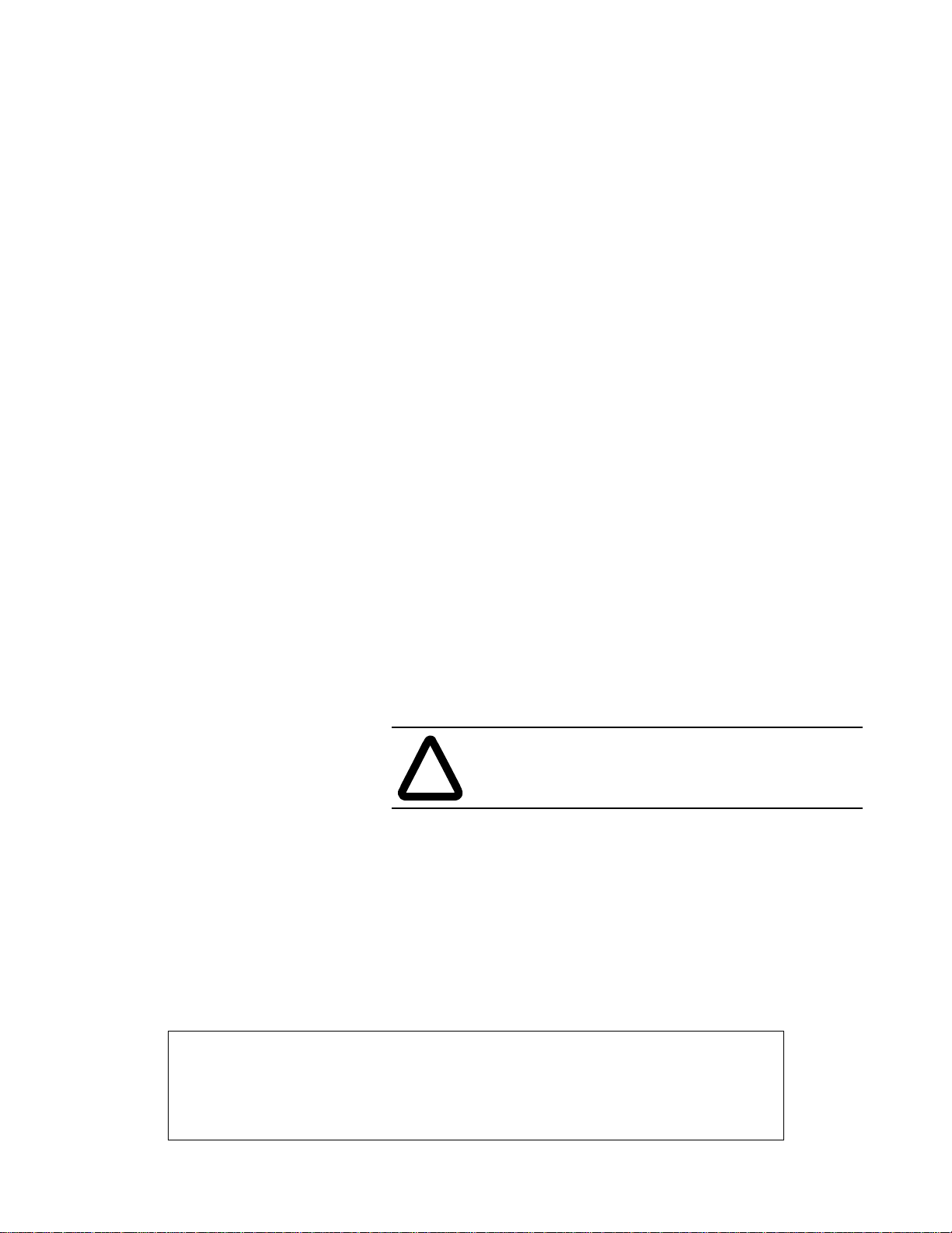
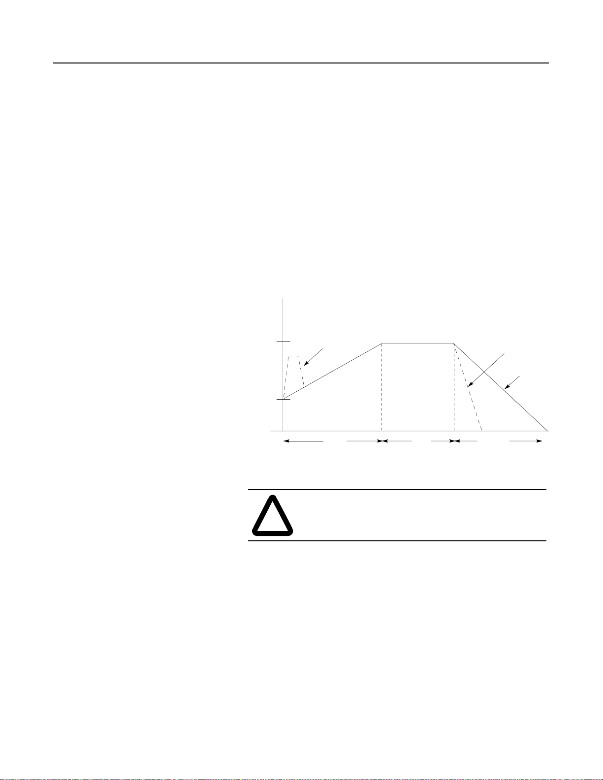
Soft Start
This mode has the most general application. The motor is given an
initial torque set ting, which is user-adjusta ble from 0 to 90% of
locked rotor torq ue. Fro m the init ial torque l e v el, t he output v olt age t o
the motor is steplessly inc rea sed during the acceleration ramp time.
The acceleration ramp time is user-adjustable from 0 to 30 seconds. If
the SMC Dialog Plus controller senses that the motor has reached the
up-to-speed condition during the voltage ramp operation, the output
voltage automatically switches to full voltage.
Figure 1.1 Soft Start
Page 13
1-3
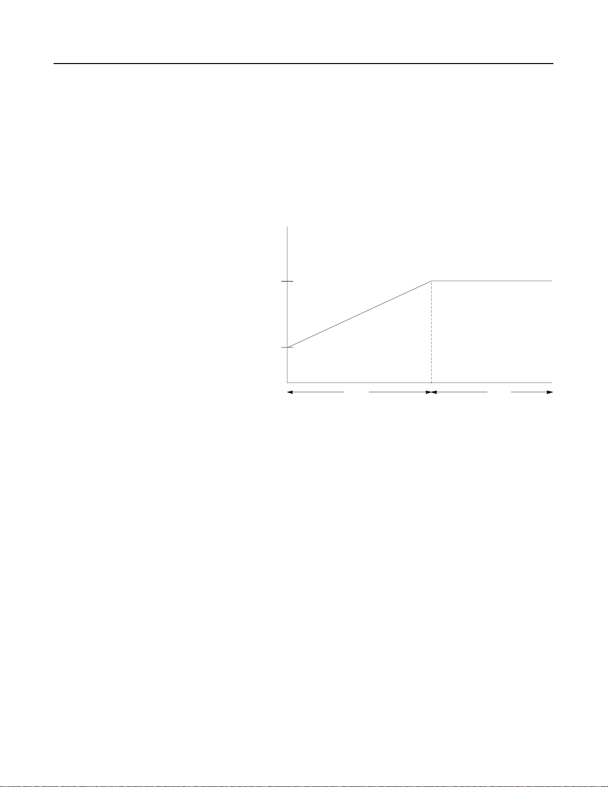
Selectable Kickstart
Product Overview
①
This feature pro vides a boost at startup to break away loads tha t
require a pulse of high torque to get started. This is intended to
provide a pulse of current that is 550% of full load current. Selectable
kickstart is user-adjustable from 0.0 to 2.0 seconds.
Figure 1.2 Selectable Kickstart
Percent
Voltage
Kickstart
100%
Initial
Torque
Current Limit Start
Start Run
②
Time (seconds)
This starting mode provides a fixed reduced voltage start; it is used
when limiting maximum starting current is necessary. The Current
Limit level is user-adjustable from 50 to 600% of the motor full loa d
ampere rating; and the current limit time is user-adjustable from 0 to
30 seconds. If the SMC Dialog Plus controller senses that the motor
has reached the up-to-speed condition during the current limit st arting
mode, the output voltage automatically switches to full voltage.
Figure 1.3 Current Limit Start
Percent
Full Load
Current
600%
50%
Start
Time (seconds)
①
Kickstart is also available with Current Limit Start.
②
The Current Limit Start mode design is based on a motor with a locked rotor current rating that is
600% of the full load current rating.
Page 14
1-4
Percent
Voltage
Initial
Torque #1
100%
Start #1 Run #1
Ramp #2
Ramp #1
Start #2
Time (seconds)
Run #2
Initial
Torque #2
100%
Product Overview
Starting Modes (cont.)
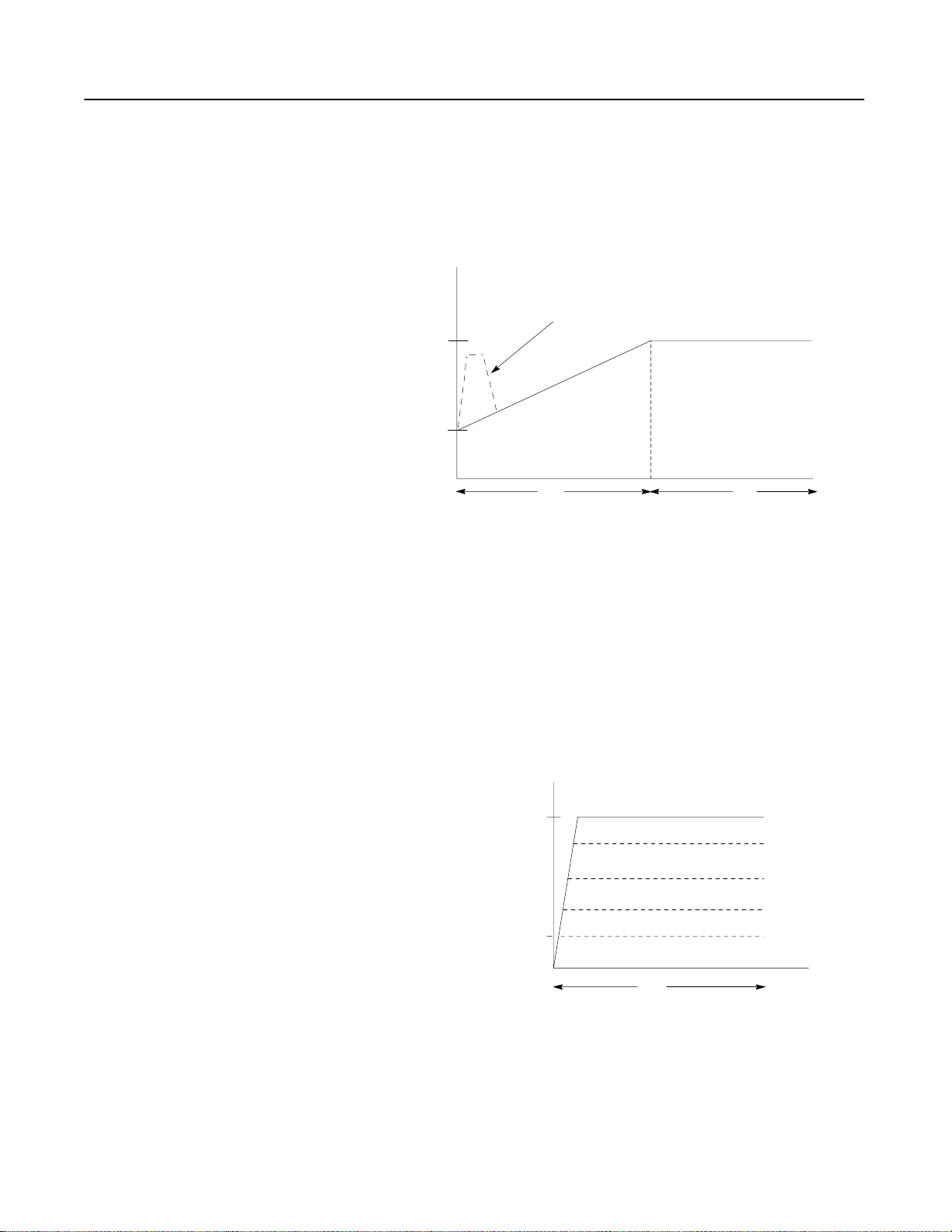
Dual Ramp Start
①
This starting mode is useful on applications that have varying loads
(and therefore varying starting torque requirements). Dual Ramp
Start allows the user to select between two separate Soft Start profiles
with separately adjustable ramp times and initial torque settings.
Figure 1.4 Dual Ramp Start
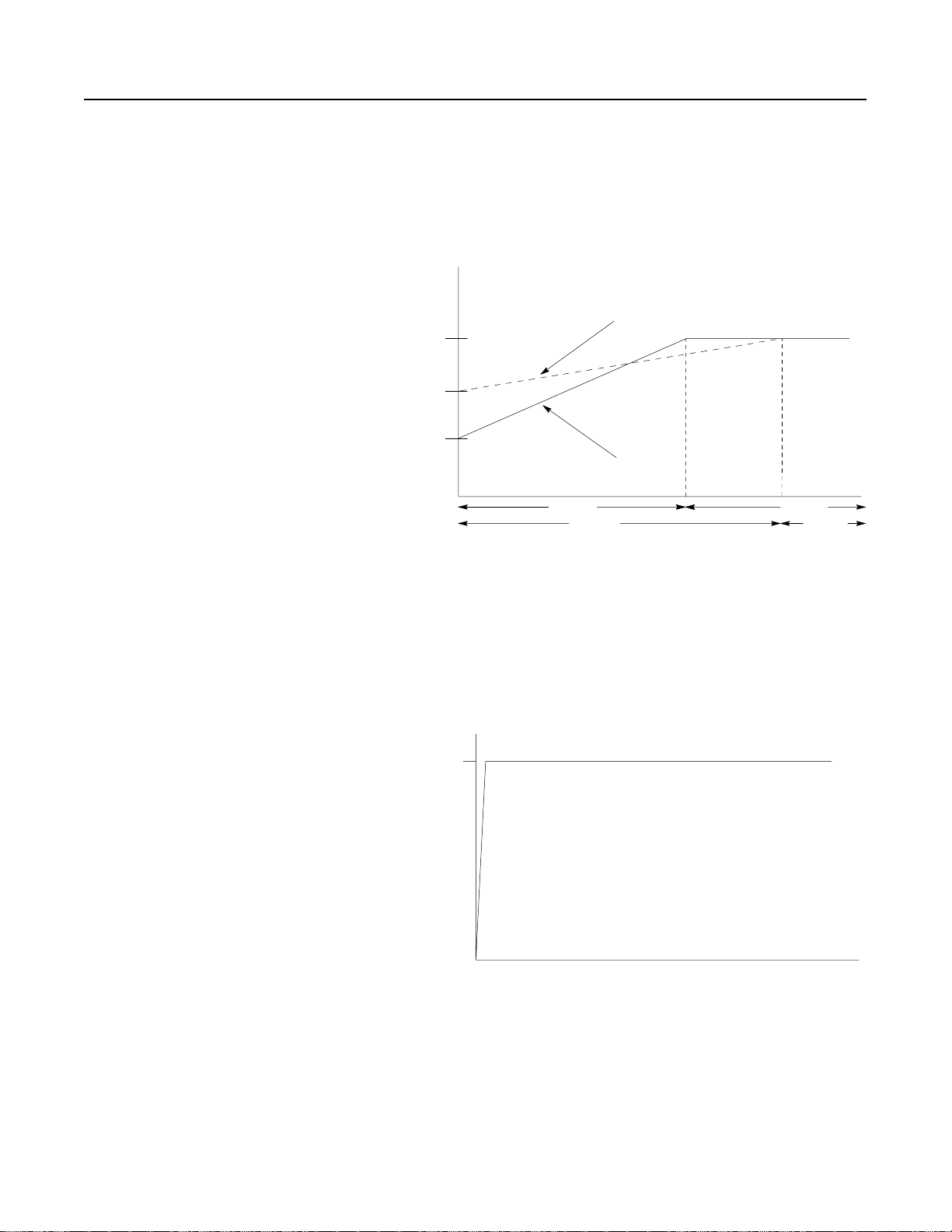
Full Voltage Start
This starting mode is used for applications requiring across-the-line
starting. The output voltage to the motor will reach full voltage
within 1/4 second.
Figure 1.5 Full Voltage Start
Percent
Voltage
Time (seconds)
①
Dual Ramp Start is available only with the standard controller.
Page 15
Product Overview
1-5
Energy Saver
Phase Rebalance
The Energy Saver feature is typically use d in app lications where the
motor is lightly loaded or unloaded for extended periods of time.
With the Energy Saver f eature enabled, the SMC Dialog Plus
controller continuously monitors motor load with its interna l
feedback circuit ry. Because SCRs control the output voltage, motor
power losses may be redu ced by decreasing the motor terminal
voltage.
Notes: (1) The Energy Saver feature is not available when a bypass
contactor is used.
(2) When Energy Saver and Phase Rebalance are both
enabled, Phase Rebalance takes precedence in operation.
Wit h the Phase Rebalance feature enabled, the SMC Dialog Plus
controller continuously monitors the incoming three-pha se line
voltage and automatically adjusts the output voltage to balance the
three phase currents dr awn by the motor.
Notes: (1) Phase Rebalance requir es that the Bulletin 825 conv erter
module is utilized.
(2) Phase Rebalance is not active during byp ass ope r ation.
(3) When Phase Rebalance and Energy Saver are both
enabled, Phase Rebalance takes precedence in operati on.
Protection and
Diagnostics
The SMC Dialog Plus controller provides the protective and
diagnostic features described below.
Overload
The SMC Dialog Plus controller meets applicable requirements as a
motor overload protective device. T hermal memory provides added
protection and is maintained even when control po wer is removed . The
built-in o verload algorithm controls the value stored in P aramet er 11,
Motor Thermal Usage; an Overload Fault will occur when this value
reaches 100%. The programming parameters below provide
application flexibility and easy setup.
Paramete r Range
Overload Class Off, 10, 15, 20, 30
Overload Reset Manual – Auto
!
Motor FLC
Service Factor
ATTENTION: During slow speed and/or braking
operations, current waveforms exhibit non-sinusoidal
characteristics. These non-sinusoida l characteristics
inhibit the controller’ s current measure ment capability .
To compensate for additional motor heating that may
result, the controller uses motor thermal modeling,
which increments motor thermal usage . This
compensation take s place when these options are in use:
Preset Slow Speed, Smart Motor Braking, Accu-Stop,
and Slow Speed with Braking.
1.0
–
0.01
999.9 Amps
–
1.99
Page 16

1-6
Product Overview
Protection and Diagnostics
(cont.)
Notes: (1) The factory default setting for Overload Class, which is
“Off,” disables overload protection. An overload trip
class and the motor’s full load current rating must be
programmed to enable overload protection.
(2) The current sensing capability of the SMC Dialog Plus
controller is disable d during bypass operation. Using a
Bulletin 825 converter module in these appli cations is
recommended to provi de curre nt feedback. Otherwise, a
separate overload relay is required.
(3) Motors with full load current ratings of 5 Amps and
below may requir e the use of the converter module
(Cat. No. 825-MCM20) for improved current
measurement accuracy.
(4) Automatic reset of an overload fault requires the start
input to be cycled in a 2-wire contr ol scheme. This
applies to the follo wing firmware relea ses: 1.07
(standard), 1A07L (Soft Stop) and 1B05L (Pump
Control) or earlier.
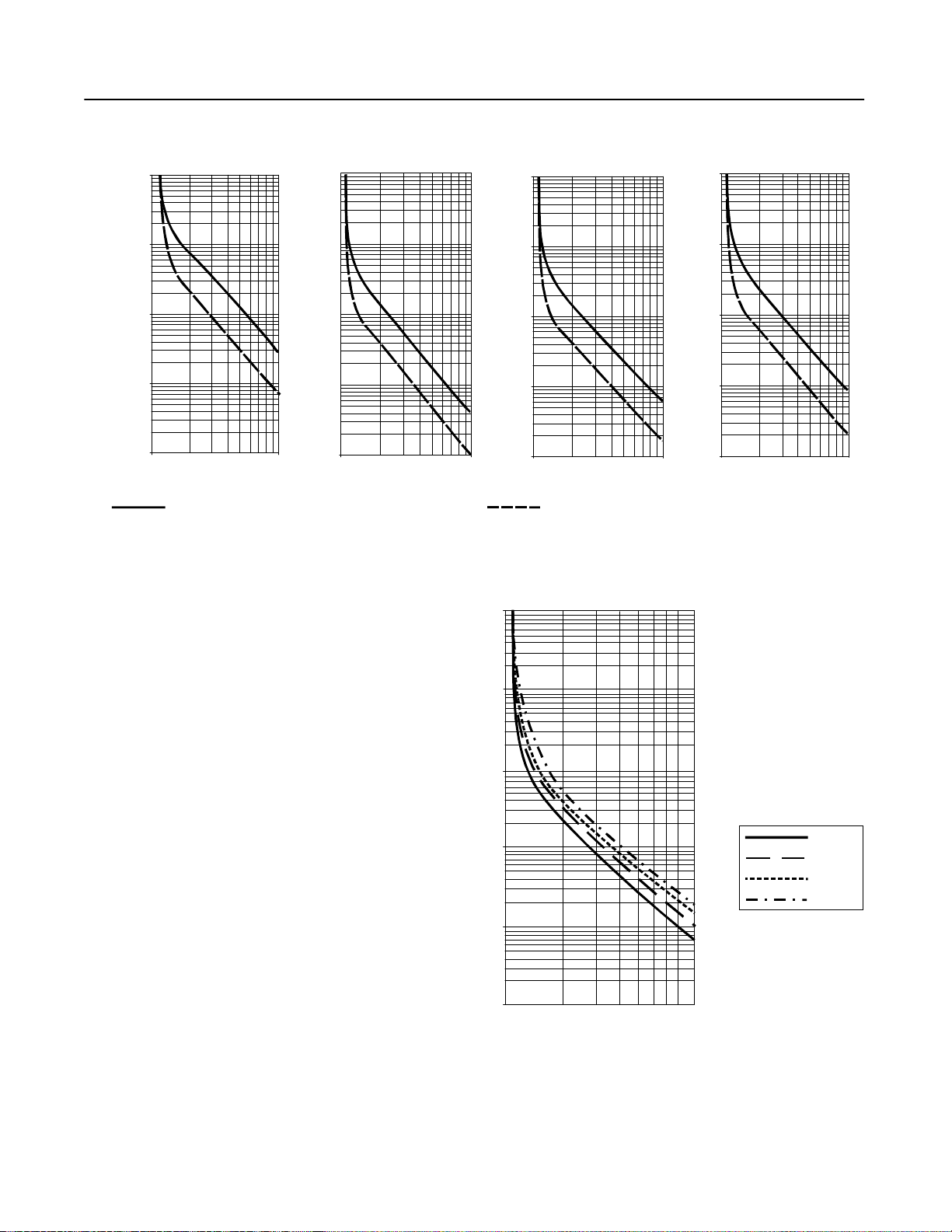
Figure 1.6 and Figure 1.7 provide the overload trip curves for the
ava ilable trip classes.
Page 17
1000.0
100.0
Product Overview
Figure 1.6 Overload Trip Curves
Class 10 Class 15 Class 20 Class 30
10000.0
1000.0
10000.0
1000.0
10000.0
1000.0
1-7
10.0
1.0
Approximate Trip Time (seconds)
0.1
1 10 2 3 9 8 7 6 5 4
100.0
10.0
Approximate Trip Time (seconds)
1.0
1 10 2 3 9 8 7 6 5 4
100.0
10.0
Approximate Trip Time (seconds)
1.0
1 10 2 3 9 8 7 6 5 4
100.0
10.0
Approximate Trip Time (seconds)
1.0
1 10 2 3 9 8 7 6 5 4
Multiples of FLC Multiples of FLC Multiples of FLC Multiples of FLC
Approximate trip time for 3-phase balanced
condition from cold start.
Approximate trip time for 3-phase balanced
condition from cold start.
Figure 1.7 Restart Trip Curves after Auto Reset
100000
1000
100
Seconds
10
1
0
100%
1000%
Percent Full Load Current Setting
Auto Reset Times:
Class 10 = 90s
Class 15 = 135s
Class 20 = 180s
Class 30 = 270s
Class 10
Class 15
Class 20
Class 30
Page 18
1-8
Stall
600%
Percent
Full
Load
Current
Time (seconds)
Programmed Start Time
100%
Running Jam
Percent
Full
Load
Current
Time (seconds)
User Programmed Trip Level
Product Overview
Protection and Diagnostics
(cont.)
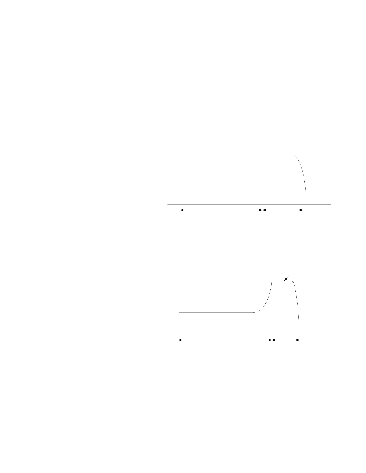
Stall Protection and Jam Detection
The SMC Dialog Plus controller provides both stall protection and
jam detection for enhanced moto r and syste m protection.
• Stall protection is user-adjustable from 0.0 to 10.0 seconds (in
addition to the ramp time programmed) .
• Jam detection allo ws the user to determine the jam lev el (up to
999% of the motor’s FLC rating) and the delay time (up to 10.0
seconds) for applica tion flexibility.
Figure 1.8 Stall Protection
Figure 1.9 Jam Detection
①
Jam detection is disabled during slow speed and braking operation.
①
Page 19

Product Overview
1-9
Open Gate
An open gate fault indic ates tha t improper SCR firing, typically
caused by an open SCR gate, has been detected on one of the power
poles. Before the controller shuts down, it will attempt to start the
motor a total of three times.
Line Faults
The SMC Dialog Plus controller continually monitors line conditions
for abnormal factors. Pre-start protection includes:
• Power Loss (with phase indication)
• Line Fault (with phase indication)
– Po wer loss
– Missing load connection
– Shorted SCR
Running protection includes:
• Line Fault (no phase indi cation)
– Power loss
– Missing load connection
– Shorted SCR
Additional programmable parameters are provided for the foll owing
protective features:
①
• Undervoltage
can be adjust ed from 0 t o 99% of the programmed
line voltage and has a programmable delay time of 0 to 99
seconds.
①
• Overvoltage
can be adju sted fro m 0 to 199% of the programmed
line voltage and has a programmable delay time of 0 to 99
seconds.
②
• Phase reversal
• Voltage unbalance
protection can be toggled either On or Off.
①
protection can be programmed for trip levels
of 0 to 25% with a programmable delay time of 0 to 99 seconds.
Underload
③
Utilizing the underload pro tection of the SMC Dialog Plus controll er ,
motor operation can be halted if a sudden drop in current is sensed.
The SMC Dialog Plus controller provides an adjusta ble underload trip
setting from 0 to 99% of the programmed motor full load current
rating. Trip delay time can be adjusted from 0 to 99 seconds.
①
Undervoltage, overvoltage, and voltage unbalance protection are disabled during braking operation.
②
Phase reversal protection is functional only at pre-start.
③
Underload protection is disabled during slow speed and braking operations.
Page 20

1-10
Product Overview
Protection and Diagnostics
(cont.)
Metering
Excessive Starts/Hour
The SMC Dialog Plus controller allows the user to program the
allowed number of starts per hour (up to 99). This helps eliminate
motor stress caused by repeated starting over a short time period.
Overtemperature
The SMC Dialog Plus controller monitors the temperature of the
SCRs by using interna l thermistors. When the po wer poles’ maxi mum
rated temperature is reache d, S CR firing is inhibited.
An overtemper ature condition can indicate inadequate ventilation,
high ambie nt temper at ure, over l o a d in g, or exc essive cy cling. After
the SCR temperature is reduced to allowable levels, the fault c an be
cleared (see page 9-1 for instructions).
Power monitoring parameters include:
• Three-phase curren t
• Three-phase v oltage
• Power in kW
• Power usage in kWH
• Power factor
• Motor thermal capacity usage
• Elapsed time
Notes: (1) The current sensing capability of the SMC Dialog Plus
controller is disable d during bypass operation. A
Bulletin 825 converter module is required to maintain t he
three-phase current, kW, kWH, and motor thermal
capacity measurements.
(2) Current measurement is not available during the slow
speed and/or braking operations of the Preset Slow
Speed, SMB Smart Motor Braking, Accu-Stop and Slow
Speed with Braking control opti ons.
(3) Voltage measurement is not available during the braking
operation of the SMB Smart Motor Braking, Accu-St op,
and Slow Speed with Braking control options.
(4) The power fac tor parameter is pro vide d as a displacement
power fa ctor value. Powe r factor measurement is
disabled during bypass operation.
(5) The elapsed time and kWH values are automatically
saved to memory every 12 hours.
(6) Motor thermal capacity usage is deter mined by the built-
in electronic thermal overload protection system. An
overload fault occurs when this value reaches 100%.
Page 21
Product Overview
1-11
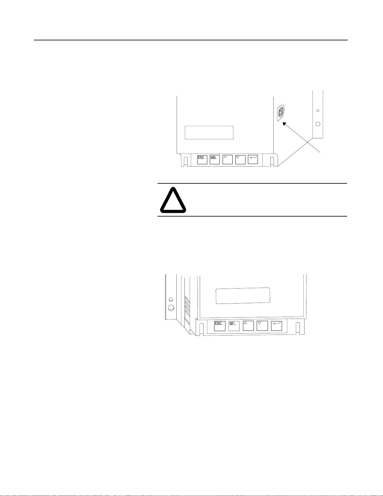
Communication
A serial interface port (called SCANport™) is provided as standard,
which allows connection to the Bulletin 1201 human interface
modules and the Bulletin 1203 communication modules.
Figure 1.10 SCANport Location
SCANport
ATTENTION: Only one peripheral devic e can be
connected to the SCANport. The maximum output
!
current through the SCANport is 100 ma.
Programming
Status Indication
Setup is easy with the built-in keypad and two-line, sixteen character
backlit LCD. Parameters are organized in a four-level menu
structure, using a text format for straightforward programming.
Figure 1.11 Built-in Keypad and LCD
Three programmable hard conta ct outputs are provided as standard.
The first two contacts are Form C and programmable for Normal/Upto-speed. The third contact is programmable as Normal/Fault.
Page 22
1-12
Start Run Soft Stop
Coast-to-rest
Soft
Stop
Kickstart
Initial
Torque
100%
Percent
Voltage
Time (seconds)
Product Overview
Control Options
The SMC Dialog Plus controller offers the control options described
below.
Importa nt: The options listed in this section are mutually exclusive
and must be specified whe n ordering. An existing
controller may be upgraded to anothe r control option by
replacing the c ontrol module. Consult yo ur nearest/local
Allen-Bradley sales office.
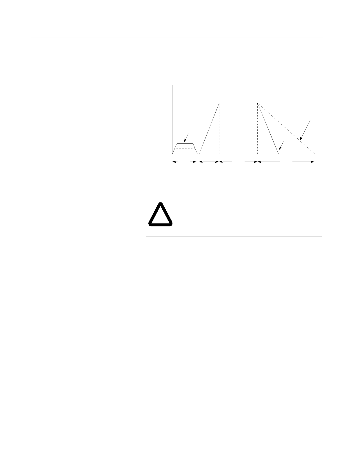
Soft Stop Option
This option can be used in applications that requir e an extended c oastto-rest. The voltage ramp down time is user-adjustable from 0 to 60
seconds and is adjusted indep endently from the starting time. The
load will stop when the output v olt age drops to a point where the load
torque is greater than the developed motor torque.
Figure 1.12 Soft Stop Option
ATTENTION: Soft Stop is not inten ded to be used as
an emergency stop. Refer to the applicable standards
!
for emergency stop requirements.
Page 23
Product Overview
Pump Start Run Pump Stop
Motor
Speed
100%
Time (seconds)
1-13
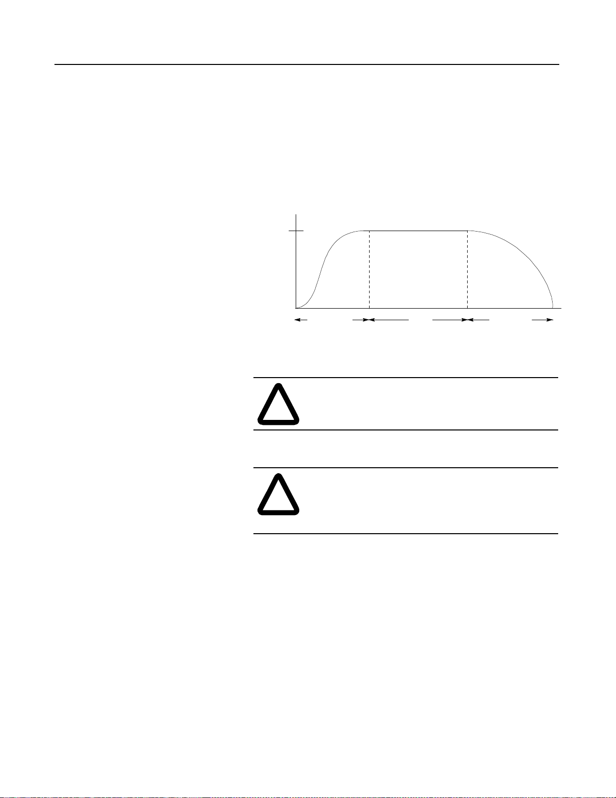
Pump Control Option
This option reduces surges during the starting and stopping of a
centrifugal pump b y smoothly accelerating and decelerating the
motor. The microprocessor analyzes the motor variables and
generates commands that contr ol the motor and reduce the possibi lity
of surges occurring in the system.
The starting time is progra mmable from 0–30 seconds, and the
stopping time is programmable from 0–120 seconds.
Figure 1.13 Pump Control Option
ATTENTION: Pump stopping is not intended to be
used as an emergency stop. Refer to the applicable
!
!
standard for emergency stop requirements.
ATTENTION: Pump stopping may cause motor
heating depending on the mechanical dynamics of the
pumping system. Therefore, select the lowest stopping
time setting that will satisfactorily stop the pump.
Preset Slow Speed Option
This option can be used in applications that require a slow speed jog
for general purpose positioning. Preset Slow Speed provides either
7% of base speed (low) or 15% of base speed (high) settings in the
forward direction. Reverse can also be programmed and offers 10%
of base speed (lo w) and 20% of base speed (high) set tings.
Page 24
1-14
Forward
15% – High
7% – Low
10% – Low
20% – High
Reverse
Run Start Time (seconds)
Start
Motor
Speed
100%
Run
Automatic Zero Speed
Shut-off
Brake
Smart Motor Braking
Coast-to-rest
Time (seconds)
Product Overview
Figure 1.14 Preset Slow Speed Option
ATTENTION: Slow speed runni ng is not intended for
continuous operation due to reduced motor cooling.
!
Control Options (cont.)
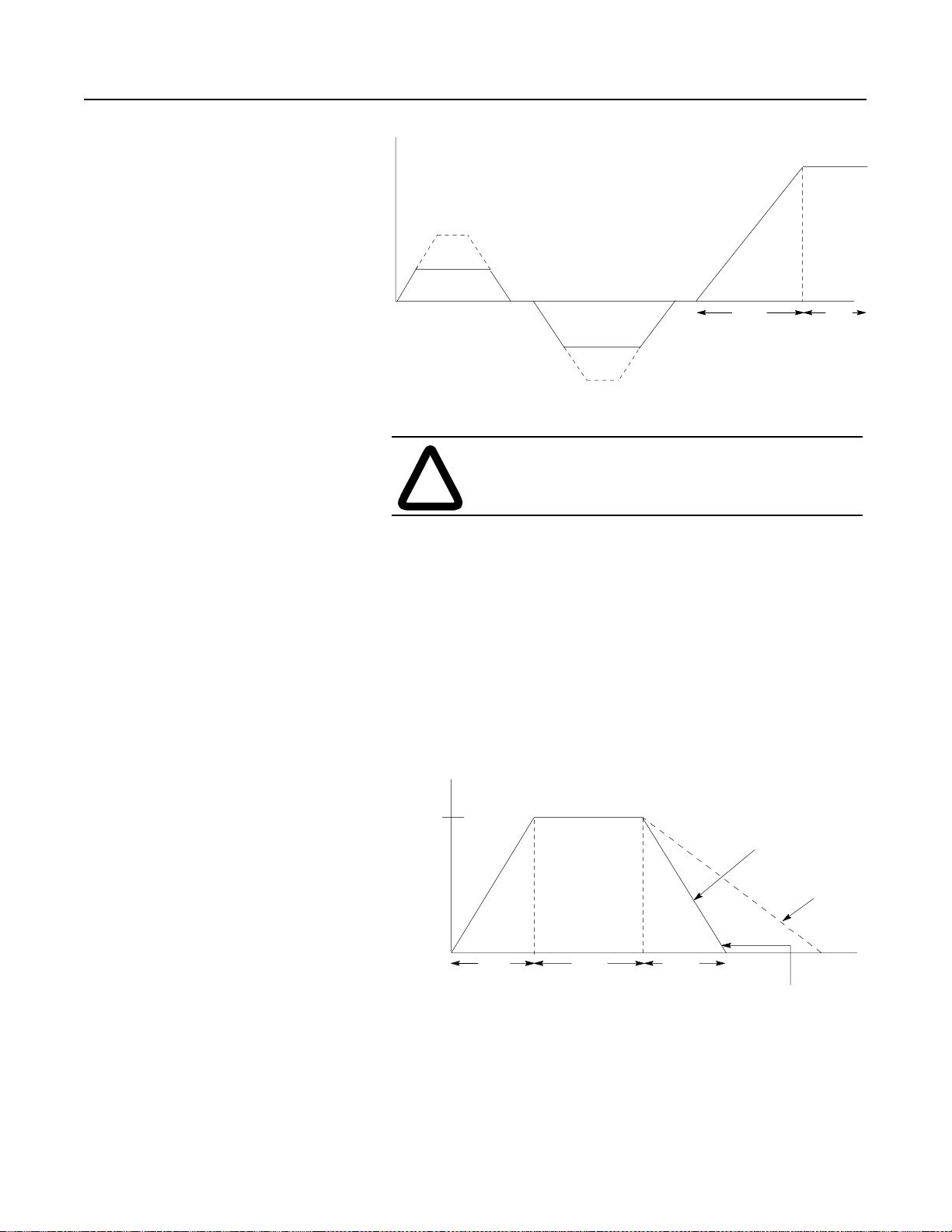
SMB Smart Motor Braking Option
This option can be used in applications that require reduced stopping
times. The SMC Dialog Plus controller incorpor ates a
microprocessor-based system that applies braking current to a
standard squirrel cage induction motor without any additional
equipment. This option offers a user-adjustable braking current
setting from 0% to 400% of the motor’s full load current rating.
Further , it provides automatic shut-off at zero speed detection.
Figure 1.15 SMB Smart Motor Braking Option
Page 25
Product Overview
Start
Run
Motor
Speed
100%
Slow
Speed
Accu-Stop
Braking
Slow
Speed
Slow Speed
Braking/Coast
7% or 15%
Time (seconds)
1-15
Note: All braking current settings in the range of 1–100% will
provide 100% braking current to the motor.
ATTENTION: SMB Smart Motor Braking is not
intended to be used as an emergency stop. Refer to
!
applicable standards fo r emer gency stop requirements.
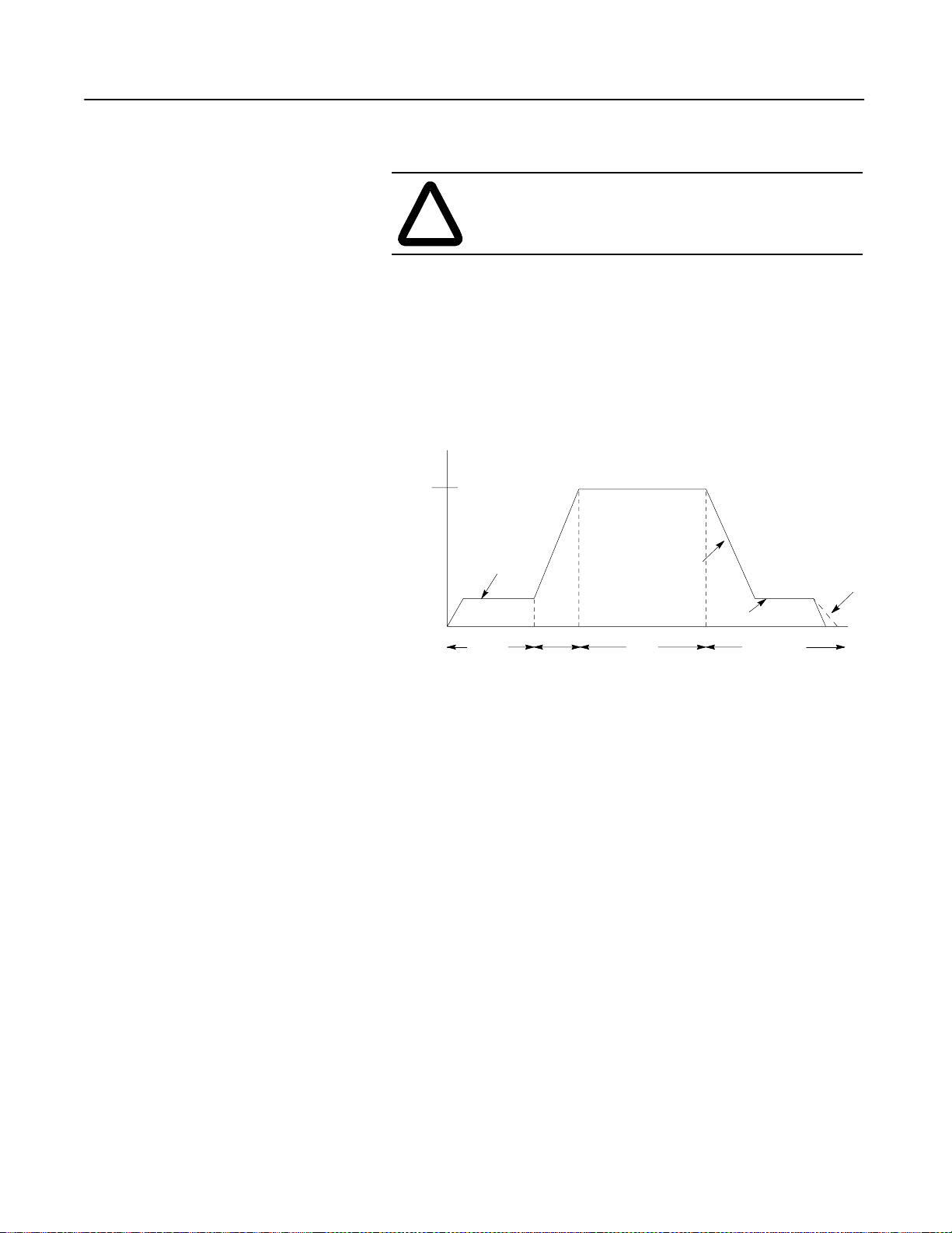
Accu-Stop Option
This option combines the benefits of the SMB Smart Motor Braking
and Preset Slo w Speed options. For general purpose positioning, the
Accu-Stop option provides a brake from full speed to the preset slow
speed setting, then brakes to stop.
Figure 1.16 Accu-Stop Option
Page 26
1-16
Motor
Speed
100%
Start
Run Slow
Speed
Braking
7% or 15%
Stop
Coast-to-rest
Time (seconds)
Product Overview
Slow Speed with Braking Option
The Slow Speed with Bra king option pr o vides a jog spe ed for pr ocess
set-up and braking-t o-stop at the end of the cycle.
Figure 1.17 Slow Speed with Braking Option
!
ATTENTION: Accu-Stop and Slow Speed with
Braking are not intended to be used as an emergency
stop. Refer to applicable standards for emergency sto p
requirements.
Page 27

Installation
Chapter 2
Receiving
Unpacking
Inspecting
Storing
It is the responsibili ty of the user to thorough ly inspect the equipment
before accepting the shipm ent from the freight company. Check the
item(s) received against the purchase order. If any items are
damaged, it is the responsibil ity of the user not to accept deli very until
the freight agent has note d the damage on the freight bill. Should any
concealed damage be found during unpac king, it is again the
responsibili ty of the user to notify the freight agent. The shipping
container must be left intact and the fr eight agen t should be requeste d
to make a visual inspection of the equipment.
Remove all packing material, wedges, or braces from within and
around the controlle r. Remove all packing material from the heat
sink.
After unpacking, check the it em(s’) nameplate catalog number
against the purchas e order.
The controller should remain in its shipping container prior to
installati on. If the equipment is not to be used for a period of time, it
must be stored according to the foll owing instructions in order to
maintain warranty c overage.
• Store in a clean, dry location.
• Store within an ambient temperature range of –20°C to +75°C
(–4°F to +167°F).
• Store within a relative humidity range of 0% to 95%,
noncondensing.
• Do not store equipment where it could be exposed to a corrosive
atmosphere.
• Do not store equipment in a construction area.
Page 28
2-2
Installation
General Precautions
In addition to the precautions listed throughout this manual, the
following sta tements, which are general to the system, must be read
and understood.
ATTENTION: The controller contains ESD
(electrostatic di scharge) sensiti ve parts and assembl ies.
!
!
!
Static control precautions are require d when installing,
testing, servicing, or repa iring the assembly.
Component damage may result if ESD control
procedures are not follo wed. If you are not familiar with
static control procedures, refer to applicable ESD
protection handbooks.
ATTENTION: An incorrectly applied o r installed
controller can damage components or reduce product
life. Wiring or application errors, such as undersizing
the motor, incorrect or inadequate AC supply, or
excessive ambient temperatures, may result in
malfunction of the system.
ATTENTION: Only personnel familiar with the
controller and associated machinery should plan or
implement the installation, start-up, and subsequent
maintenance of the sys tem. Failure to do this may r esult
in personal injury and/or equipment damage.
Heat Dissipation
SMC Rating
Max. Watts
24A 35A 54A 97A 135A 180A 240A 360A 500A 650A 720A 850A 1000A
110 150 200 285 410 660 935 1170 1400 2025 2250 2400 2760
Enclosures
The following table provides the maximum heat dissipation at rated
current for the controllers. For currents lower than rat ed value, heat
dissipation will be red uced.
Table 2.A Maximum Heat Dissipation
The open-style desig n of t he SMC Dialog Plus c ontroll er re quires t hat
it be installed in an enclosure. The internal temperature of the
enclosure must be kept within the range of 0°C to 50°C.
Page 29

Installation
2-3
Ventilated Enclosures
For Type 1 (IP42) enclosures, the following guidelines are
recommended to limit the maximum controller ambient temperature.
There should be a clearance of at least six inc hes (15 cm) above and
below the contr oller. This area allows air to fl ow thro ugh the
heatsink. Ventilation openings are required above and below this air
space.
The ventilation outlet should be placed at least six inches (15 cm)
above the con troller with the ventilation inlet placed near the bottom
of the enclosure. A filter is required to preve nt contaminants from
entering the enclosu re.
Use the table below to det erm ine the minimum ventilation openings
and fan/blower requirements.
Table 2.B Minimum Ventilation Openings
SMC Rating Top Cutout
24–54A
97 and 135A
180A
240A
360A
500A
650A
720A
850A
1000A
65 cm
(10 in2)
233 cm
(36 in2)
13 × 51
(5 × 20)
13 × 51
(5 × 20)
13 × 51
(5 × 20)
13 × 41
(5 × 16)
②
②
②
②
①③
2
2
Bottom Cutout
2
65 cm
(10 in2)
2
233 cm
(36 in2)
②
②
②
②
13 × 76
(5 × 30)
13 × 76
(5 × 30)
13 × 76
(5 × 30)
13 × 76
(5 × 30)
①③
Fan Size
110 CFM
110 CFM
100 CFM
250 CFM
(2) 250 CFM
275 CFM
(3) 240 CFM
(3) 240 CFM
(3) 240 CFM
(3) 240 CFM
①
①
Cutout size assumes 50% blockage (filters, louvers, etc.)
②
Cutout size is the same as required for the particular fan or blower being used.
③
Dimensions are in centimeters (inches in parentheses).
Non-ventilated Enclosures
For Type 12 (IP54) or non-ventilated enclosures, it is recommended
that a bypass contactor be used. This will allow the SMC Dialog Plus
controller t o bring the m otor up- to-spee d. After the c ontroller is up to
full volta ge, it is bypassed. Note that the Energy Saver , Phase
Rebalance, some metering functions, and some protecti ve features of
the controller may no longe r be available. See Figure 3.17 on page 313 for this confi guration.
Page 30
2-4
Installation
Mounting
D
C
The controller is c on v ect ion coole d. Additiona lly, units rated for 97A
and above are fan cooled. It is important to locate the controller in a
position that allows air to flow vertically through the power module.
The controller mus t be m ounted with he ats ink fins in a vertica l
plane and hav e a minimum of six inches ( 15 cm) free space above
and below the controller.
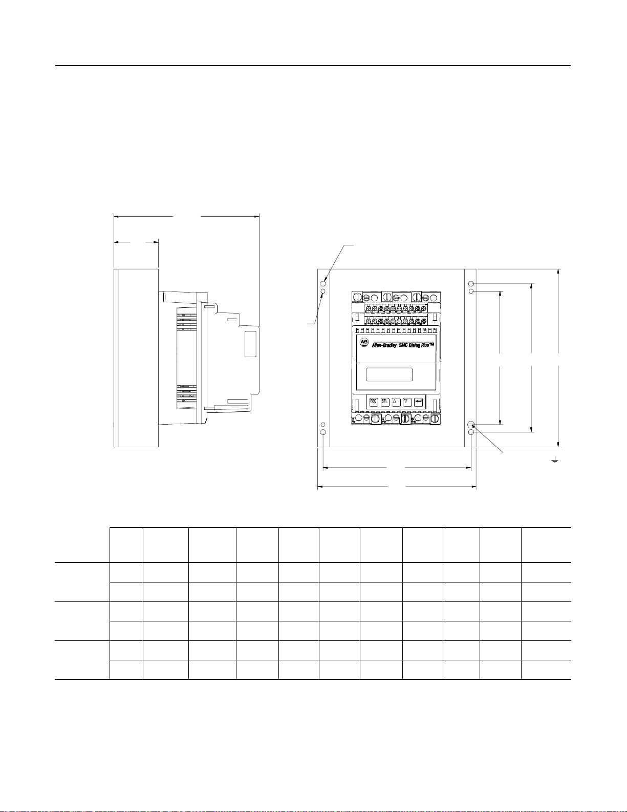
Dimensions
Figure 2.1 Dimensions: 24, 35, and 54 Amp Controllers
Ø .28 in.
(7.14 mm)
4 Mtg. Holes
Ø .22 in.
(5.56 mm)
4 Mtg. Holes
G F B
E
A
Unit
24A
Controller
35A
Controller
54A
Controller
All dimensions are approximate and are not intended for manufacturing purposes. Refer to the nearest Allen-Bradley sales office for complete dimension drawings.
mm 154 180 185 50 140 160 140 10 20 4.5 kg
in. 6-1/16 7-3/32 7-19/64 1-31/32 5-33/64 6-5/16 5-33/64 13/32 51/64 10 lbs.
mm 214 240 195 60 200 200 180 20 30 6.8 kg
in. 8-7/16 9-39/64 7-11/16 2-23/64 7-7/8 7-7/8 7-3/32 51/64 1-3/16 15 lbs.
mm 244 290 225 90 230 240 200 25 45 11.3 kg
in. 9-39/64 11-22/64 8-7/8 3-35/64 9-1/64 9-29/64 7-7/8 63/64 1-25/32 25 lbs.
A
Width
B
Height
C
Depth
DE F GHJ
Ground Screw
(10-32)
Approx.
Ship. Wt.
Page 31

Installation
Figure 2.2 Dimensions: 97 and 135 Amp Controllers
2-5
A
E
Power Terminal
M10 Bolt
6 Places
C
D H
G
B
F
Ground
Screw (M6)
Fan
.281 in.
Termina ls
(Ø 7.14 mm)
4 Mtg. Holes
Unit
97A
Controller
135A
Controller
All dimensions are approximate and are not intended for manufacturing purposes. Refer to the nearest Allen-Bradley sales office for complete dimension drawings.
mm 248 336 256.2 128 220 250 40.4 14 10.4 kg
in. 9-49/64 13-15/64 10-3/32 5-3/64 8-21/32 9-27/32 1-39/64 9/16 23 lbs.
mm 248 336 256.2 128 220 250 40.4 14 11.8 kg
in. 9-49/64 13-15/64 10-3/32 5-3/64 8-21/32 9-27/32 1-39/64 9/16 26 lbs.
A
Width
B
Height
C
Depth
DE F GH
Approx.
Ship. Wt.
Page 32

2-6
Installation
Mounting (cont.)
.281 (7.1)
Dia.
6 Mtg. Holes
.281 (7.1)
Rad.
2 Key Holes
A
D
P
180, 240, and 360 Amp
Dbl. Lug Mtg.
Figure 2.3 Dimensions: 180 through 360 Amp Controllers
C
Q
E
F
G
J
B
H
S
M
Ground Nut
(1/4-20)
K
R
N
Terminal Detail
.136 (3.5) Dia.
#8-32 UNC-2B
.413 (10.5) Dia.
1.02
.984
(25.9)
(25)
.531
(13.5)
2.250
1.161
(29.5)
(57)
L
A
Unit
WidthBHeightCDepth
mm 273 580 294.2 245 5 81 221 361 453 56 251 167 35 19.3 8.4 28 4.7 25 kg
180A
Cont.
in. 10.750 22.063 11.583 9.647 .207 3.195 8.695 14.195 17.817 2.213 9.880 6.562 1.375 .76 .250 1.1 .187 55 lbs.
mm 273 580 294.2 245 5 81 221 361 453 56 251 167 35 19.3 8.4 28 4.7 30 kg
240–
360A
Cont.
All dimensions are approximate and are not intended for manufacturing purposes. Refer to the nearest Allen-Bradley sales office for complete dimension drawings.
10.750 22.063 11.583 9.647 .207 3.195 8.695 14.195 17.817 2.213 9.880 6.562 1.375 .76 .250 1.1 .187 65 lbs.
in.
D E F G H J K L M N P QRS
Approx.
Ship.
Wt.
Page 33

.531 in. (13.5 mm)
for 1/2 Bolts Typ.
Installation
Figure 2.4 Dimensions: 500 Amp Controller
M
N
P
2-7
E
L
.312 in. (7.9 mm)
6 Mtg. Holes
Unit
A
HeightBWidthCDepth
J
F
K
A
G
Q Q
H
B
DEFGHJKLMNPQ
Ground Nut
(1/4-20)
D
C
Approx.
Ship.
Wt.
mm 588.4 508 310.7 183 51.4 50.8 469.9 489 19 196.9 393.7 38.9 18.6 17.5 136 40.8 kg
in. 23-11/64 20 12-15/64 7-13/16 2-1/32 2 18-1/2 19-1/4 3/4 7-3/4 15-1/2 1-17/32 47/64 11/16 5-11/32 90 lbs.
All dimensions are approximate and are not intended for manufacturing purposes. Refer to the nearest Allen-Bradley sales office for complete dimension drawings.
Page 34

2-8
Installation
Mounting (cont.)
2.0
(50.8)
.688
(17.5)
1.312 (33.3)
4.0
(101.6)
650–720 Amp
.515
(13.1)
Dia. Typ.
1.312 (33.3)
B
.56 Dia. (Ø 14.2)
2 – Lifting Holes
.5 Dia. (Ø 12.7)
6 – Holes
Figure 2.5 Dimensions: 650-1000 Amp Controllers
A
D
E
R R
F
G
H
T
.75 Dia.
(Ø 19.1)
2 – Holes
J
K
C
P
L
M
Q
N
.105 Steel
Sheet
(2.67)
(63.5)
.64
(16.3)
Typ.
.64
(16.3)
850–1000 Amp
Typical Line and Load Bus
Unit
650 and
720A
Controller
850 and
1000A
Controller
All dimensions are approximate and are not intended for manufacturing purposes. Refer to the nearest Allen-BradleyAllen-Bradley sales office for complete dimension
drawings.
mm 32.0 60.0 15.83 30.25 6.0 12.13 .875 .875 2.0 58.25 9.935 5.475 .75 329 317.5 246.1
in. 812.8 1524.0 402.1 768.35 152.4 308.0 22.22 22.23 50.8 1479.55 252.35 139.06 19.05 13 12.5 9.69
mm 32.0 60.0 15.83 30.25 6.0 12.13 .875 .875 2.0 58.25 9.935 5.475 .75 383 375 246.1
in. 812.8 1524.0 402.1 768.35 152.4 308.0 22.22 22.23 50.8 1479.55 252.35 139.06 19.05 15 14.75 9.69
.688
(17.5)
.67
(17)
.64
(16.3)
A
WidthBHeightCDepth
(wide range: #6 solid to 250 MCM stranded)
DEFGHJ K L MNPQR
Grounding Lug
5.0
2.5
(127)
Page 35

Installation
2-9
Power Factor
Correction Capacitors
The controller can be installed on a system with power factor
correction (PFC) capacitors. The capacitors must be located on the
line side of the c ontroll er. This must be done to pr e v ent damage to the
SCRs in the SMC Dialog Plus controller.
When discharged, a capacitor essentially has zero impedance. For
switching, sufficient impedance should be connected in series with
the capacitor bank to limit the inrush current. One method for
limiting the surge current is to add inductance in the capacitor’s
conductors. This can be accomplished by creating turns or coils in
the power connections to the capacitors.
• 250V – 6 inch diameter coil, 6 loops
• 480–600V – 6 inch diameter coil, 8 loops
T ak e care in mounting the coils so that they are not stack ed directly on
top of each other; stacking will cause a canceling ef f ect. Also, mount
the coils on ins ulated supports away from metal parts so they will not
act as induction heater s. If an isolation contactor is used, put
capacitors in front of contactor.
Note: For further instructions, consult the PFC capacitor vendor.
Figure 2.6 Typical Wiring Diagram for Power Factor Correction Capacitors
➀
➁
IC
L1/1 T1/2
Branch Circuit
Protection
➀
➀➀➀
Power Factor
Correction Capacitors
L2/3 T2/4
L3/5 T3/6
SMC Dialog
Plus
➀
➁
➀
Motor
➀
Customer supplied
Not required
Page 36

2-10
Installation
Fast Acting
Current-limiting
Fuses
SMC
Rating
24A
35A
54A
97A
135A
180A
240A
360A
500A
650A
720A
850A
1000A
Short-circui t protec tion g uidelines are provided in Appendix A of this
manual. Enhanced SCR protection may be obtained with the use of
fast acting current-limiting fuses. Table 2.C provides a listing of
fuses that are coordinate d to protect the controller SCRs in the event
of a ground fault or short- circui t at the connected loa d. If SCR fusing
is not used, the controller power modules may be damaged and
require replacement. Supplementary SCR fusing, however, is not
required by the NFPA 70 (National Electric Code).
Table 2.C Recommended Fuses
Fuse Manufacturer Cat. No.
Bussman Shawmut Edison (Brush) Ferraz Littlefuse
SPP-4F60
170M 3610-63
SPP-4F100
170M 3612-100
SPP-4F150
170M 3614-160
SPP-4F300
170M 3617-315
SPP-4F300
170M 3617-315
SPP-4F400
170M 3619-400
SPP-6F400
170M 5608-400
SPP-6F600
170M 5612-630
SPP-6F800
170M 6613-900
SPP-6F800
170M 6613-900
SPP-5F600
170M 5612-630
SPP-7F1200
170M 6615-1100
SPP-6F800
170M 6613-900
②
②
②
②
A70P70 XL70F080 A070F060 L70S60
A70P100 XL70F125 A070F100 L70S100
A70P200 XL70F200 A070F150 L70S150
A70P300 XL70F300 A070F300 L70S300
A70P300 XL70F300 A070F300 L70S300
A70P400 XL70F400 A070F400 L70S400
A70P500 XL70F500 A070F400 L70S400
A70P800 XL70F600 A070F800 L70S600
A70P1000 XL70F500
A70P1000 XL70F500
A70P1200 XL70F600
A70P1000
A70P1000
Note: Fuse size listed is for 230V, 460V, or 575V.
①
Fuse manufacturer’s cross reference of the fuse Cat. Nos. listed here may not provide proper
coordination.
②
Two fuses per phase are required for these controller ratings.
②
②
— A070F1200 L70S800
— A070F1200 L70S800
①
②
②
②
A070F800 L70S800
A070F800 L70S500
A070F800 L70S500
!
!
ATTENTION: The fast acting current- limiting fuses
specified in Table 2.C may not provide branch circuit
protection. Branch circuit pro tection in accordance
with applicable electr ical codes may require add itional
fusing (or a circuit breaker) even though fast acting
current-limiting fuses are used.
ATTENTION: Applications requiring extended
acceleration times or high duty cycle s may experience
nuisance trippi ng of the co ordinated fa st acti ng currentlimiting fuses. This type of fuse has a limited thermal
capacity that is less than that of the SCRs they are
designed to protect. This makes them susceptible to
thermal fatigue.
Page 37

Installation
2-11
Protective Modules
Motor Overload
Protection
Prot ective modules containing metal oxide varistors (MOVs) and
capacitors c an be ins talle d on controlle rs r ated 24A to 360A to prote ct
the powe r component s f rom elec tric al tra nsients and/or high elec trical
noise. The pr otective modules clip voltage transients generated on
the lines to pre vent such surges from damaging the SCRs. The
capa c i tors i n the protective modules are used to shunt noise energy
away from the contr oller electronics. Surge protection is provide d as
standard for controlle r s rated 500–1000A.
ATTENTION: When installing or inspecting the
protective module, make sure that the controller has
!
Thermal motor ov erload protection is provided as standard (though it
must be programmed) with the SMC Dialog Plus controller. If the
overl oad trip class is less than the accelerati on time of the motor,
nuisance tripping may occur.
been disconnected from the po wer source. The
protectiv e modul e should be inspecte d periodi cally for
damage or discoloration. Replace if nece ssary.
ATTENTION: Overload protecti on should be
properly coordinated with the motor.
!
Three special applic ations require consideration: bypass, two-speed
motors, and multi-motor protection.
Bypass
In a bypass configuration, the SMC Dialog Plus controller lose s
current sensing capability. It is recommended that a Bulletin 825
converter module be used to provide curr ent feedback to the SMC
Dialog Plus controller for these applications to maintain the thermal
memory and to maintain the SMC Dialog Plus controller’s power
monitoring capability. It is possible, however, to use a traditional
electromechani cal overload relay for b ypass configurations.
Two-speed Motors
The SMC Dialog Plus controller has ov er load prot ection a va il able for
single speed motors. Whe n th e SMC Dial og Plus contr oller i s a pplie d
to a two-speed motor, the Overload Class parameter must be
programmed to OFF and separate overload relays must be provided
for each speed.
Multi-motor Protection
If the SMC Dialog Plus contr oller is c ont rolling mor e than one motor,
individual overload protection is required for each motor.
Page 38

2-12
Installation
Human Interface Module
The Bulletin 1201 human interface modules may be used to program
and control the SMC Dialog Plus controlle r. The human interface
modules have two sections: a display pa nel and a control panel. The
display panel duplicate s the 2-line, 16-character backlit LCD display
and programming keypa d found on front of the SMC Dialog Plus
controller. Refer to Chapter 4 for a description of the programming
keys; refer to Appendix D for a listing of human interface module
catalog numbers that are compatible with the controller.
The control panel pro vides the operator interface to the controller.
Start
The green start b utton, when presse d, will be gi n motor
operation.
Stop
The red stop button, when pressed, will halt motor
operation.
JOG
Jog
The jog button is active only when a control option is
present. Pressing the jog but ton wi ll ini tiate the opt ion
maneuver (for example: Pump Stop).
ATTENTION: The Bulletin 1201 human interface
module’ s stop push b utt on i s not inte nded to be us ed a s
!
All other contro ls available with the various human interface
modules are non-functional with the SMC Dialog Plus controller .
an emergency stop. Refer to the applicable standards
for emergency stop requirements.
Page 39

SMC Dialog Plus Controller
Installation
2-13
Connecting the Human Interface Module to the Controller
Figure 2.7 sho ws th e connection of the S MC Dialog Plus c ontroller to
a human interface module. S ee Figure 3.14 on page 3-10 for the
control wiring diagra m that enables start-stop control from a human
interface module.
Figure 2.7 SMC Dialog Plus Controller with Human Interface Module
1
14
13
12
11
3
172718
16
15
5
20
19
Latching
Mechanism
Pull back moving part (connector body) to disconnect
Bulletin 1202
Cable
cable from the SCANport connection.
30
29
28
26
25
24
23
22
21
Human Interface Module
Control Enable
To enable motor control from a connected human interface module,
follow the procedure below with the connected human inte rface
module’s programming keys.
Note: Series A and Series B human interface modules require
different procedures. Be sure to use the correct table.
Page 40

2-14
Installation
Human Interface
Module (cont.)
Series A Human Interface Modules
Description Action Display
——
1. Press any key to access
the Choose Mode
function.
2. Scroll with the Up/Down
keys until the Program
option appears.
3. Press the Enter key to
access the Program
option.
4. Scroll with the Up/Down
keys to the Linear List
option.
5. Press the Enter key to
access the Linear List
programming group.
STOPPED
0.0 AMPS
CHOOSE MODE
_ _ _ _ _
or
or
CHOOSE MODE
PROGRAM
PROGRAM
_ _ _ _ _
PROGRAM
LINEAR LIST
VOLTS PHASE A-B
0 VOLTS 1
6. Scroll with the Up/Down
keys to parameter
number 85 – Logic
or
LOGIC MASK
085
Mask.
7. Press the Select key to
move the cursor to the
second line to modify
the parameter.
①
8. Press the Up key until
the value 4 appears.
9. Press the Enter key to
accept the new setting.
Zero and 4 are the only valid settings.
①
LOGIC MASK
085
LOGIC MASK
485
LOGIC MASK
485
Note: If a hum an interface module is disconnected from the SMC
Dialog Plus controller while the Logic Mask is set to 4, a
“Comm Fault” will occur.
Page 41

Series B Human Interface Modules
Description Action Display
Installation
2-15
——
1. Press any key to access
the Choose Mode
function.
2. Scroll with the Up/Down
keys until the Control
Logic option is
presented.
3. Press the Enter key to
access Control Logic
options.
4. Press the Select key to
access the settings
available.
5. Use the Up/Down keys
to obtain the Enable
option.
6. Press the Enter key to
accept.
STOPPED
0.0 AMPS
CHOOSE MODE
_ _ _ _ _
or
or
CHOOSE MODE
CONTROL STATUS
CONTROL LOGIC
DISABLE
CONTROL LOGIC
DISABLE
CONTROL LOGIC
ENABLE
CONTROL LOGIC
ENABLE
Note: If a hum an interface module is disconnected from the SMC
Dialog Plus controller while Control Logic is enabled, a
“Comm Fault” will occur.
Page 42

2-16
Installation
Communication
Modules
15
251626
3
19
18
17
28
27
1
14
13
12
11
24
23
22
21
SMC Dialog Plus Controller
The Bulletin 1203 communicati on module al lows the user to connect
the SMC Dialog Plus controller to v arious networks and
communication protocols . The figure below sho ws how the cont roller
and the communication module connec t.
Figure 2.8 SMC Dialog Plus Controller with Communication Module
5
Latching
Mechanism
20
Pull back moving part (connector body) to disconnect
cable from the SCANport connection.
30
29
V+
V-
G
Communication Module
Bulletin 1202
Cable
Converter Modules
The Bulletin 825 con verter module provides three-phase current
feedback to the SMC Dialog Plus controller for metering and
overload protection during phase rebalance and bypass operation.
Select the converter module based on the motor full load current
(FLC) rating. Table 2.A details the information for proper selection.
Table 2.A Converter Module Selection Guide
Motor FLC Range Cat. No.
1–12.5A 825-MCM20
9–100A 825-MCM180
64–360A 825-MCM630
Page 43

Installation
Figure 2.9 shows the connection between the controller and the
module.
Figure 2.9 Converter Module Connection Interface
L1
T1 T2 T3
L2 L3
Converter
➀
Module
Cable (provided as
standard with the
converter module)
➁
150-NFS
Fanning Strip
21 22 23 24 25 26 27 28 29 30
2-17
①
The converter module rating must be programmed in the calibration group for proper current
measurement scaling.
②
Cable length is three meters. Only the cable provided with the converter module is compatible with
the SMC Dialog Plus controller. Use of any other cable may result in faulty controller operation.
Page 44

2-18
Installation
Converter Modules (cont.)
For applications in which the motor’s full load current rating is
greater than 360A, three additional current transformers with 5A
secondaries are requ ir ed. The figure below illustrates the connection
of the current transformers to the converter module.
Figure 2.10 Current Transformer Connection to Converter Module
➀➁
Current Transformer
L1
T1 T3
L2
T2
L3
Converter Module
➂
Electromagnetic
Compatibility (EMC)
The current transformer (CT) ration must be programmed in the calibration group for proper current
①
measurement scaling. See page 5-2 for instructions on programming this parameter.
②
Another current transformer connects L2 and T2, and another connects L3 and T3.
③
The converter module, Cat No. 825-MCM20, must be used in these applications.
.
ATTENTION: This product has been designed for
Class A equipment. Use of the product in domestic
!
envir onments may cause radio interference, in which
case, the installer may need to employ additional
mitigation methods.
The followi ng guidelines are provided for EMC install ation
compliance.
Enclosure
Install the product in a grounde d metal enclosure.
Grounding
Connect a grounding conductor to the screw or terminal provided as
standard on each controller. Refer to Figure 2.1 through Figure 2.5
for grounding provision location.
Page 45

Installation
2-19
Wiring
Wire in an industrial control application can be divided into three
groups: power, control, and signal. The following recom mendations
for physical separa tion between these groups is pro vided to reduce the
coupling eff ect.
• Different wire gr o ups should cross at 90° inside an enclosur e.
• Minimum spacing be tween different wire groups in the same tray
should be six inches (16 cm).
• Wire runs outside an enclosure should be run in conduit or have
shielding/armo r with equivalent attenuation.
• Different wire gr o ups should be run in separate conduits.
• Minimum spacing between conduits co nta ining differe n t wire
groups should be three inches (8 cm).
Accessory Requirements
When connection of the Bulletin 825 converter module or Bulletin
1202 communication c able is required, a f err ite core suppressor (FairRite PN 2643802702 or equal) should be used in conjuncti on. Mount
the suppressor as close to the controller as practical, wrapping the
cable twice through the suppr ess or.
Page 46

2-20
Installation
Page 47

Wiring
Chapter 3
Terminal Locations
The SMC Dialog Plus controller wiring terminal locations are shown
in Figure 3.1 through Figure 3.4. Make wiring connections as
indicated in the typical connection diagrams. Connect the line to
terminals L1/1, L2/3, and L3/5. Connect the load to terminals T1/2,
T2/4, and T3/6. For controllers rated 24–135A, a grounding screw is
provided to ground the heatsink per applicable codes. For controllers
rated 180A–1000A, a grounding lug is provided on the mounting
plate.
Figure 3.1 Wiring Terminal Locations (24 to 54 Amp)
1121132312
L1
1
14241525162617271828192920
22
L2
3
L3
5
Input Power
Connections
Control
30
Circuit
Connections
ESC. SEL .
2
T1
4
T2
6
T3
Output Power
Figure 3.2 Wiring Terminal Locations (97 and 135 Amp)
Input Power
Connections
Control
Circuit
Connections
Output Power
Connections
Connections
Fan
Power
Connections
Page 48

3-2
Wiring
Terminal Locations (cont.)
Input Power
Connections
Control
Circuit
Connections
Output Power
Connections
Figure 3.3 Wiring Terminal Locations (180 to 360 Amp)
Control Wiring Access Door
Fan Power
Connections
TB3
12 3 4 5
Figure 3.4 Wiring Terminal Locations (500 Amp)
Input Power
Connections
Fan Power
Connections
Control Circuit
Connections
Output Power
Connections
Page 49

Wiring
Figure 3.5 Wiring Terminal Locations (650 to 1000 Amp)
Input and
Output Power
Connections
Control Circuit
Connections
Fan Power
Connections
Power Wiring
3-3
24–54A
The power modules for controllers rated 24A–54A have internal
mechanical-type lugs to accept line and load cables. Table 3.A and
Table 3.B provide the lug wire capacity and tightening torque
requirements.
Table 3.A Lug Wire Capacity
Metric AWG
2.5–25 mm
2
#14–#4
Table 3.B Tightening Torque
Tightening Torque
Wire Size
To rq ue
2.5–6 mm
(14–10 AWG)
2.80 N-m
(25 Lb-in)
2
10 mm
(8 AWG)
3.4 N-m
(30 Lb-in)
2
16–25 mm
(6–4 AWG)
3.95 N-m
(35 Lb-in)
2
97–1000A
Power lugs are available as optional kits. Each kit contains three lugs.
The number of terminal lug kits required is listed in the table below.
Table 3.C also provides the lug wire capacity and the tightening
torque requirements.
Page 50

3-4
Wiring
Terminal Locations (cont.)
Control Power
Table 3.C Lug Wire Capacity and Tightening Torque
SMC
Rating
97–
135A
180–
360A
500A 199-LG1
650–
720A
850–
1000A
Lug Kit
Cat. No.
199-LF1
199-LF1
199-LG1
199-LJ1
Conductor
Range
16–120 mm
(#6–4/0 AWG)
16–120 mm
(#6–4/0 AWG)
25–240 mm
(#4–500 AWG)
50–240 mm
(1/0–500 AWG)
50–240 mm
[(2) 1/0–500 AWG]
2
2
2
2
2
Max. No.
Lugs/Pole
Line
Load
Side
Side
33
66
66
99
66
Tightening Torque
Wire –
Lug
31 N-m
(275 lb-in)
31 N-m
(275 lb-in)
42 N-m
(375 lb-in)
42 N-m
(375 lb-in)
42 N-m
(375 lb-in)
Lug –
Busbar
31 N-m
(275 lb-in)
31 N-m
(275 lb-in)
45 N-m
(400 lb-in)
45 N-m
(400 lb-in)
45 N-m
(400 lb-in)
Control Voltage
Depending upon the catalog number ord ere d, the SMC Dialog Plus
controller will accept a contr ol power input of:
• 100
• 24V AC, (–15/+10%), 1 phase, 50/60 Hz
240V AC, (–15/+10%), 1 pha se, 50/60 Hz
–
• 24V DC, (–20/+10%), 1 phase
Refer to the product nameplate.
Connect control power to the controller at terminals 11 and 12. The
control po wer requirement for the control module is 40 VA. For
controllers rat ed 97A
1000A, control power is also required for the
–
heatsink fans as defined in Table 3.D. Depending on the specific
application, additional control circuit transformer VA capacity may
be required.
Table 3.D Heatsink Fan Control Power
SMC Rating Heatsink Fan VA
97–360A 45
500A 145
650–1000A 320
Control Wiring
Table 3.E provides the control terminal wire capacity and the
tightening torque requirements. Each control terminal will accept a
maximum of two wires.
Table 3.E Control Wiring and Tightening Torque
Wire Size Torque
0.75–2.5 mm
2
(#18–#14)
.8 N-m (7 lb-in.)
Page 51

Wiring
3-5
Fan Power
Controllers rated 97A–1000A have heats ink fan(s). Refer to Table 3.D
for the control power VA requirements of the heatsink fans.
Fan Terminations
See Figure 3.2 to Figure 3.4 for fan power connection locations.
ATTENTION: The fan jumpers have been factory
installed for 110/120 VAC input. Refer to Figure 3.6
!
Figure 3.6 97A and 135A Fan Terminations
through Figure 3.8 for 220/240 VAC fan wiring. Note
that 220/240 VAC fan wiring is not available for the
650A–1000A controllers . After wiring f or the 97A and
135A controllers is complete, replace cont rol terminal
strip cover.
Factory Set
110/120 VAC
1
2
Jumpers
3
To
Supply
Optional
220/240 VAC
1
2
Jumper
3
To
Supply
4
Figure 3.7 180A to 500A Fan Terminations
Factory Set
110/120 VAC
To
Supply
Jumpers Jumper
1 2 3 4 5
Figure 3.8 650A to 1000A Fan Terminations
Factory Set
110/120 VAC
To
Supply
Note: 220/240 VAC is not available.
4
Optional
220/240 VAC
To
Supply
1 2 3 4 5
1 2 3 4 5
6
Page 52

3-6
Wiring
Control Terminal
Designations
As shown in Figure 3.9, the SMC Dialog Plus controller contains 20
control terminals on the front of the controller.
Figure 3.9 SMC Dialog Plus Controller Control Terminals
20
19
18
17
16
15
14
13
12
11
30
29
28
27
26
25
24
23
22
21
Ter min al
Number
11 Control Power Input 21 Not Used
12 Control Power Common 22 Not Used
13 Controller Enable Input
14 Logic Ground 24 Not Used
15 Dual Ramp/Option Input
16 Start Input
17 Stop Input
18 Auxiliary Relay Common 28 Converter Module Fanning Strip Connection
19 N.O. Auxiliary Contact #1 (Normal/Up-to-speed) 29 N.O./N.C. Auxiliary Contact #3 (Normal/Fault)
20 N.C. Auxiliary Contact #2 (Normal/Up-to-speed) 30 N.O./N.C. Auxiliary Contact #3 (Normal/Fault)
Description
①
①
①
①
Ter min al
Number
23 Not Used
25 Converter Module Fanning Strip Connection
26 Converter Module Fanning Strip Connection
27 Converter Module Fanning Strip Connection
Description
②
②
②
②
Do not connect any additional loads to these terminals. These “parasitic” loads may cause problems with operation, which may result in false starting and stopping.
①
②
When control power is absent from terminals 11 and 12, this contact will be normally open. Upon application of control power, the contact will take the state, normally
open or normally closed, as programmed.
Grounding
Provision
Provision for connecting a field installed grounding conductor is
provided on each controller . It is shown in Figure 3.10 and is located
on the heatsink. This symbol is the ground connection identific ation
symbol as defined by IEC Publication 417, Symbol 5019.
If the pr o tec tive c onductor is not connected to the heatsink, the
plating and/or pain t must be cleaned from the four mounting holes or
four star washers (t ooth lock washers) must be used.
Figure 3.10 Grounding Provision
Page 53

Wiring
Stop
➀
11 12 13 14 15 16 17 18 19 20
21 22 23 24 25 26 27 28 29 30
Start
➀
Internal
Auxiliary
Contacts
SMC Dialog Plus
Control Terminals
3-Phase
Input Power
Branch
Protection
➀
Fast-acting
SCR Fuses
(optional)
➀
SMC Dialog Plus
Controller
M
➀
L1/1
L2/3
L3/5
T1/2
T2/4
T3/6
➀
➀
➀
➁
3-7
Standard Controller
Wiring Diagrams
Figure 3.11 through Figure 3.22 show typical wiring for the SMC
Dialog Plus controller.
Figure 3.11 Typical Wiring Diagram for Standard Controller
Customer supplied.
①
②
Refer to the controller nameplate to verify the rating of the control power input voltage.
Page 54

3-8
Two-wire Device
➀
11 12 13 14 15 16 17 18 19 20
21 22 23 24 25 26 27 28 29 30
Internal
Auxiliary
Contacts
3-Phase
Input Power
Branch
Protection
➀
Fast-acting
SCR Fuses
(optional)
➀
SMC Dialog Plus
Controller
M
➀
L1/1
L2/3
L3/5
T1/2
T2/4
T3/6
➀
➀
➀
➁
SMC Dialog Plus
Control Terminals
Wiring
Standard Controller
Wiring Diagrams (cont.)
Figure 3.12 Typical Wiring Diagram for Two-Wire Control or Programmable
Control Interfacing
Customer supplied.
①
②
Refer to the controller nameplate to verify the rating of the control power input voltage.
Notes: (1) Programmable controller interfacing in this diagram refers to hard-wiring between the
PLC’s output contacts and the SMC Dialog Plus controller’s control terminals. For a
wiring diagram related to programmable controller interfacing via the SMC Dialog
Plus controller’s SCANport, refer to Figure 3.14.
(2) The OFF state leakage current for a solid-state device must be less than 6 mA.
Page 55

Stop
➀
11 12 13 14 15 16 17 18 19 20
21 22 23 24 25 26 27 28 29 30
Start
➀
Ramp 1 ➀Ramp 2
Internal
Auxiliary
Contacts
3-Phase
Input Power
Branch
Protection
➀
Fast-acting
SCR Fuses
(optional)
➀
SMC Dialog Plus
Controller
M
➀
L1/1
L2/3
L3/5
T1/2
T2/4
T3/6
➀
➀
➀
➁
SMC Dialog Plus
Control Terminals
Wiring
3-9
Figure 3.13 Typical Wiring Diagram for Dual Ramp Applications
Customer supplied.
①
②
Refer to the controller nameplate to verify the rating of the control power input voltage.
Note: The Dual Ramp feature is available only with the standard control version.
Page 56

3-10
11 12 13 14 15 16 17 18 19 20
21 22 23 24 25 26 27 28 29 30
Internal
Auxiliary
Contacts
3-Phase
Input Power
Branch
Protection
➀
Fast-acting
SCR Fuses
(optional)
➀
M
➀
L1/1
L2/3
L3/5
T1/2
T2/4
T3/6
➀
➀
➀
➁
➂
SMC Dialog Plus
Controller
SMC Dialog Plus
Control Terminals
Wiring
Standard Controller
Wiring Diagrams (cont.)
Figure 3.14 Typical Wiring Diagram for Start-Stop Control via the SCANport
Note: Use this wiring diagram when start-stop will come from
either a Bulletin 1201 human interface module or a Bulletin
1203 communication module connec ted to the SMC Dialog
Plus controller’s SCANport.
①
②
③
Customer supplied.
If the Soft Stop, Pump Control, or the SMB Smart Motor Braking option is installed, place additional
jumper to terminal 15.
Refer to the controller nameplate to verify the rating of the control power input voltage.
Page 57

Stop
➀
M
➀
Start
➀
3-Phase
Input Power
Branch
Protection
➀
Fast-acting
SCR Fuses
(optional)
➀
M
➀
M
➀
➀
➀
➀ ➁
➀
➂
L1/1
L2/3
L3/5
OL
T1/2
T2/4
T3/6
11 12 13 14 15 16 17 18 19 20
21 22 23 24 25 26 27 28 29 30
Internal
Auxiliary
Contacts
Auxiliary contacts
set for Normal
SMC Dialog Plus
Controller
SMC Dialog Plus
Control Terminals
Existing Motor
Starter
➀
Wiring
3-11
Figure 3.15 Typical Wiring Diagram for Retrofit Applications
Customer supplied.
①
②
Overload protection should be disabled in the SMC Dialog Plus controller.
③
Refer to the controller nameplate to verify the rating of the control power input voltage.
Page 58

3-12
Stop
➀
➀
3-Phase
Input Power
Branch
Protection
➀
Fast-acting
SCR Fuses
(optional)
➀
Isolation
Contactor
(IC)
➀
M
➀
IC
➀
➀
➀
➀
➁
11 12 13 14
21 22 23
Contacts
Auxiliary contacts
set for Normal
SMC Dialog Plus
Controller
SMC Dialog Plus
Control Terminals
Wiring
Standard Controller
Wiring Diagrams (cont.)
Figure 3.16 Typical Wiring Diagram for Isolation Applications
L1/1
T1/2
L2/3
T2/4
L3/5
T3/6
Start
Customer supplied.
①
②
Refer to the controller nameplate to verify the rating of the control power input voltage.
15 16 17 18 19 20
Internal
Auxiliary
24 25 26 27 28 29 30
Page 59

Wiring
Stop
➀
Start
➀
3-Phase
Input Power
Branch
Bypass Contactor (BC)
➀
Protection
➀
Fast-acting
SCR Fuses
(optional)
➀
Bulletin 825
Converter
Module
➀ ➁
M
➀
BC
➀
➀
➀
➀
➂
11 12 13 14 15 16 17 18 19
21 22 23 24 25 26 27 28 29
Contacts
Fanning Strip
➀
To
Bulletin 825
Converter
Module
Auxiliary
contacts set for
Up-to-speed
SMC
Dialog Plus
Controller
SMC Dialog Plus
Figure 3.17 Typical Wiring Diagram for Bypass Applications
T1/2
L1/1
T2/4
L2/3
T3/6
L3/5
3-13
20
Control Terminals
Internal
Auxiliary
30
Customer supplied.
①
②
The Bulletin 825 Converter Module is required when the SMC Dialog Plus controller will be providing
motor overload protection during bypass operation.
③
Refer to the controller nameplate to verify the rating of the control power input voltage.
Page 60

3-14
Stop
➀
Start
➀
Bypass Contactor (BC)
➀
➁
3-Phase
Input Power
Branch
Protection
➀
Fast-acting
SCR Fuses
(optional)
➀
➀
Isolation
Contactor
(IC)
➀
M
➀
BC
➀
➀
➀
➀
➀
L1/1
L2/3
L3/5
T1/2
T2/4
T3/6
11 12 13 14 15 16 17 18 19 20
21 22 23 24 25 26 27 28 29 30
IC
Fanning Strip
➀
To
Bulletin 825
Converter
Module
Auxiliary contacts
set for Up-to-speed
Auxiliary contact
set for Normal and N.O.
SMC Dialog Plus
Controller
SMC Dialog Plus
Control Terminals
Wiring
Standard Controller
Wiring Diagrams (cont.)
Figure 3.18 Typical Wiring Diagram for Bypass with Isolation Applications
Bulletin 825 Converter Module
Customer supplied.
①
②
Refer to the controller nameplate to verify the rating of the control power input voltage.
Page 61

Wiring
Stop
➀
Start
➀
➁
3-Phase
Input Power
Branch
Protection
➀
Fast-acting
SCR Fuses
(optional)
➀
M
➀
➀
➀
➀
L1/1
L2/3
L3/5
T1/2
T2/4
T3/6
11
21
ST
Auxiliary contact
set for Fault
and N.O.
SMC Dialog Plus
Controller
SMC Dialog Plus
Control Terminals
Figure 3.19 Typical Wiring Diagram for Shunt Trip Applications
Shunt Trip Circuit Breaker
3-15
12 13 14 15 16 17 18 19 20
➀
22 23 24 25 26 27 28 29 30
Customer supplied.
①
②
Refer to the controller nameplate to verify the rating of the control power input voltage.
Page 62

3-16
Wiring
Standard Controller
Wiring Diagrams (cont.)
3-Phase
Input Power
➀
Stop
Branch
Protection
➀
➀
FOR REV
Figure 3.20 Typical Wiring Diagram for Single Speed Reversing Applications
➀
➀
OFF
F
R
Reversing Contactors
➀
➀
F
R
➀
R
F
➀
➀
Bulletin 825
Coverter
➀
Module
(optional)
➀
Fast-acting
SCR Fuses
(optional)
L1/1
L2/3
L3/5
SMC Dialog Plus
Controller
➀
T1/2
T2/4
T3/6
M
➀
➀
R
➀
F
➁
11 12 13 14 15 16 17 18 19 20
SMC Dialog Plus
Control Terminals
21 22 23 24 25 26 27 28 29 30
Customer supplied.
①
②
Refer to the controller nameplate to verify the rating of the control power input rating.
Internal
Auxiliary
Contacts
Notes: (1) Minimum transition time for reversing direction is 1/2 second.
(2) Phase Reversal protection
must
be disabled in reversing applications.
Page 63

Wiring
3-Phase
Input Power
Branch
Protection
➀
Two-speed Motor Starter
➀
Fast-acting
SCR Fuses
(optional)
➀
M
➀
➀
➀
➀
L1/1
L2/3
L3/5
T1/2
T2/4
T3/6
L
H
H
H
➁
➁
Stop
➀
High
Low
LOL
➀
HOL
➀
H
L
L
1 sec.
1 sec.
H
L
H
H
L
➂
➀
➀
➀
➀
➀
➀
➀
➀
➀
➀
11 12 13 14 15 16 17 18 19 20
21 22 23 24 25 26 27 28 29 30
Internal
Auxiliary
Contacts
SMC Dialog Plus
Controller
SMC Dialog Plus
Control Terminals
Figure 3.21 Typical Wiring Diagram for Two-speed Applications
3-17
①
②
③
Customer supplied.
Two-speed, consequent pole installations.
Refer to the controller nameplate to verify the rating of the control power input voltage.
Page 64

3-18
HA
3-Phase
Input Power
Branch
Protection
➀
Fast-acting
SCR Fuses
(optional)
➀
M
➀
➀
➀
➀
➀
L1/1
L2/3
L3/5
T1/2
T2/4
T3/6
➁
11 12 13 14 15 16 17 18 19 20
21 22 23 24 25 26 27 28 29 30
Internal
Auxiliary
Contacts
SMC Dialog Plus
Controller
SMC Dialog Plus
Control Terminals
Wiring
Standard Controller
Wiring Diagrams (cont.)
Figure 3.22 Typical Wiring Diagram for Hand-Off-Auto (SCANport) Control
Customer supplied.
①
②
Refer to the controller nameplate to verify the rating of the control power input voltage.
Page 65

Programming
Chapter 4
Overview
Keypad Description
This chapter provides a basic understanding of the programming
keypad built into the SMC Dialog Plus controller. This chapter also
describes programming the cont roller by modifying the parameters.
The keys found on the front of the SMC Dialog Plus contr oller are
described below.
Escape
ESC
Select
SEL
Up/Down
Arrows
Pressing the Escape key causes the programming system
to move up one level in the menu structure.
The Select key has two functions:
• Pressing the Select key alternately causes the top or
bottom line of the display to become active (indicated
by flashing first character).
• In parameter modification with series A FRN 3.00 or
greater and series B human interface modules,
Select moves the cursor from the least significant
digit to the most significant.
These keys are used to increment and decrement a
parameter value or to scroll through the different modes,
groups, and parameters.
Programming Menu
Enter
When pressed, a mode or group will be selected, or a
parameter value will be entered into memory. After a
parameter value has been entered into memory, the top
line of display will automatically become active, allowing
the user to scroll to the next parameter.
Parameters are organize d in a four-level menu struc t ur e for
straightforw ard programming. Figure 4.1 details the programming
menu structure and the four-level hierarchy.
Page 66

4-2
Programming
Programming Menu (cont.)
Control
➁
Status
Display
read only
Figure 4.1 Menu Structure Hierarchy
Power-up and
Status Display
or
Choose Mode
Program
read/write
or
or
or
or
Password
See page 4-5
OPERATION LEVEL
Search
read only
See page 4-5
MODE LEVELMODE LEVEL
➂➃➂➃
➀
Control Logic
Fault Queue
or
Linear
List
Metering
See
Chapter 6
Basic Setup Advanced Setup
➁
The SMC Dialog Plus controller does not support EEPROM, Link, Process, or Start-up modes.
①
②
Steps back one level.
③
Control Status and Search are only available when using a Series B Bulletin 1201 human interface module.
④
Password protected.
⑤
English is currently the only available language.
Faults
Calibrate
See
Chapter 5
Language
⑤
GROUP LEVEL
Page 67

Programming
Figure 4.1 (Cont.) Menu Structure Hierarchy
or
4-3
Linear
List
Metering
See
Chapter 6
Basic Setup Advanced Setup
Faults
➀
Calibrate
See
Chapter 5
Language
➁
GROUP LEVEL
➀
Volts Phase A–B
Volts Phase B–C
Volts Phase C–A
Current Phase A
Current Phase B
Current Phase C
Wattmeter
Kilowatt Hours
Elapsed Time
Power Factor
Mtr. Therm. Usage
SMC Option
Starting Mode
Ramp Time #1
Initial Torque #1
Curr. Limit Level
Kickstart Time
Stall Delay
Energy Saver
Aux Contacts 1&2
Aux Contact #3
Contact 3 Config
(Option Setting)
Parameter Mgmt
④
SMC Option
Starting Mode
Dual Ramp
Ramp Time #1
Initial Torque #1
Ramp Time #2
Initial Torque #2
Curr. Limit Level
Kickstart Time
Stall Delay
Energy Saver
Aux Contacts 1&2
Aux Contact #3
Contact 3 Config
(Option Setting)
Clear Fault
Fault Buffer #1
Fault Buffer #2
Fault Buffer #3
Fault Buffer #4
Fault Buffer #5
Overload Class
Overload Reset
Motor HP Rating
Motor kW Rating
Line Voltage
Motor FLC
Service Factor
Motor Code Letter
LRC Ration
Converter Rating
CT Ratio
Calibration
Enter Calib. Amps
Current Phase A
Parameter Mgmt.
④
Undervolt Level
Undervolt Delay
Overvolt Level
Overvolt Delay
Jam Level
Jam Delay
Unbalance Level
Unbalance Delay
Rebalance
Underload Level
Underload Delay
Phase Reversal
Starts per Hour
Restart Attempts
Restart Delay
ETM Reset
Parameter Mgmt
④
③
PARAMETER LEVEL
Steps back one level.
①
②
English is currently the only available language.
③
For further information on parameters, see Appendix B.
④
For further information on parameter management, see pages 4-6 and 4-7.
Page 68

4-4
Programming
Programming Menu (cont.)
Table 4.A Parameter Linear List
Parameter No. Description Parameter No. Description
1 Volts Phase A–B 45 Slow Speed Dir.
2 Volts Phase B–C 46 Slow Accel Cur.
3 Volts Phase C–A 47 Slow Running Cur.
4 Current Phase A 48 Braking Current
5 Current Phase B 49 Factory Use
6 Current Phase C 50 Factory Use
7 Wattmeter 51 Stopping Current
8 Kilowatt Hours 52 Undervolt Level
9 Elapsed Time 53 Undervolt Delay
10 Power Factor 54 Overvolt Level
11 Mtr. Therm Usage 55 Overvolt Delay
12 Factory Use 56 Jam Level
13 Factory Use 57 Jam Delay
14 SMC Option 58 Unbalance Level
15 ETM Reset 59 Rebalance
16 Factory Use 60 Underload Level
17 Parameter Mgmt. 61 Underload Delay
18 Clear Fault 62 Phase Reversal
19 Fault Buffer #1 63 Starts per Hour
20 Fault Buffer #2 64 Restart Attempts
21 Fault Buffer #3 65 Restart Delay
22 Fault Buffer #4 66 Factory Use
23 Fault Buffer #5 67 Factory Use
24 Factory Use 68 Factory Use
25 Factory Use 69 Line Voltage
26 Factory Use 70 Motor FLC
27 Factory Use 71 Factory Use
28 Starting Mode 72 Mtr. Code Letter
29 Dual Ramp 73 Factory Use
30 Ramp Time #1 74 Converter Rating
31 Initial Torque #1 75 CT Ratio
32 Ramp Time #2 76 Calibration
33 Initial Torque #2 77 Enter Calib. Amps
34 Curr. Limit Level 78 Language Select
35 Kickstart Time 79 Motor HP Rating
36 Overload Class 80 Motor kW Rating
37 Stall Delay 81 LRC Ratio
38 Energy Saver 82 Factory Use
39 Aux Contacts #1&2 83 Factory Use
40 Aux Contact #3 84 Service Factor
41 Contact 3 Config 85 Logic Mask
42 Stop Time 86 Unbalance Delay
43 Factory Use 87 S/W Version
44 Slow Speed Sel. 88 Overload Reset
Page 69

Programming
4-5
Password
The SMC Dialog Plus control ler allows the user to limit access to the
programming system through password protection. This feature is a
disabled with a facto ry-se t parameter with a default setting of 0. T o
modify the password or login after a password is programmed,
complete the procedure below.
Description Action Display
——
1. Press any key to go
from the status display
to the Choose Mode
menu.
2. Scroll with the Up/
Down keys until the
Password option
appears.
3. Press the Enter key to
access the Password
menu.
or
STOPPED
0.0 AMPS
CHOOSE MODE
DISPLAY
CHOOSE MODE
PASSW ORD
PASSW ORD
|MODIFY
Options:
Login, Modify
Logout
Search
4. Press the Enter key.
5. Press the Up/Down
keys to enter the
desired number. If you
are modifying the
password, make a note
of it as displayed.
6. Press the Enter key
after you have
completed modifying
the password.
After you have completed the programming process, re-enter the Password mode to log out. This
①
will eliminate unauthorized access to the programming system.
①
or
ENTER PASSWORD
_ _ _ _ _
ENTER PASSWORD
#####
CHOOSE MODE
PASSW ORD
Note: If you lose or forget the password, contact your nearest
Allen-Bradle y sales office. You can also call 1-800-765-
SMCS (765-7627) for assistance.
The Search mode allows the user to view only those parameters that
have settings other than the factory defa ult values. This mode is
ava ilable only when using Bulletin 1201 human interface module.
Page 70

4-6
Programming
Parameter Management
Before you begin progr amming, it’s important to understand how the
controller memory is:
• structured withi n the SMC Dialog Plus cont roller
• used on power-up and during normal operation
Refer to Figure 4.2 and the explanations below.
Figure 4.2 Memory Block Diagram
EEPROM RAM ROM
Random Access Memory (RAM)
This is the work area of the controller after it is powered up. When
you modify parameters in the Program mode, the new va lues are
stored in RAM. When power is applied to the controller, para meter
values stored in the EEPROM are copied to RAM. RAM is volatile
and the values store d in this area are lost when the controller is
powered down.
Read-only Memory (ROM)
The SMC Dialog Plus controller comes with factory default
parameter va lues. These settings are stored in nonvolatile ROM and
are displayed the first time you enter the Program mode.
Electrically Erasable Programmable Read-only Memory
(EEPROM)
The SMC Dialog Plus controller provides a nonvolatile area for
storing user-modified parameter values in the EEPROM.
Page 71

Using Parameter Management
Description Action Display
Saving to EEPROM
To ensure that the newl y
modified parameters are
not lost if control power is
removed from the
controller, store the values
into EEPROM.
Recalling from EEPROM
Parameters stored in
EEPROM can be manually
brought to RAM by
directing the controller to
recall the values stored in
its EEPROM.
Recalling Defaults
After parameter values
have been modified and
saved to EEPROM, factory
default settings can still be
re-initialized.
Programming
4-7
PARAMETER MGMT
STORE IN EE
PARAMETER MGMT
RECLL FRM EE
PARAMETER MGMT
DEFAULT INT
Page 72

4-8
Programming
Parameter Modification
All parameters are modif ied using the same method. The basic steps
to performing parameter modification are described bel ow.
Note: Parameter values modif ied while the motor is operating are
not valid until the next start sequence begins.
Description Action Display
——
1. Press any key to go from the
status display to the Choose
Mode menu.
2. Scroll with the Up/Down keys
until the Program option
appears.
3. Press the Enter key to access
the Program menu.
4. Scroll with the Up/Down keys
until the option you want to use
(Basic Setup, Advanced Setup,
etc.) appears. For this example,
Basic Setup will be used.
or
or
STOPPED
0.0 AMPS
CHOOSE MODE
DISPLAY
CHOOSE MODE
PROGRAM
PROGRAM
METERING
PROGRAM
BASIC SETUP
5. Press Enter to select the Basic
Setup group.
6. Scroll to the next parameter by
using the Up key.
7. To modify the parameter, press
the Select button to move the
cursor to the second line.
8. Scroll to the option of your
choice by using the Up/Down
keys. For this example, we will
choose Current Limit.
9. Press the Enter key to accept
the new setting.
10. Scroll to the next parameter by
using the Up key. Continue the
process until all desired settings
are entered.
11. Press the Enter key to save the
new settings to EEPROM.
SMC OPTION
STANDARD
STARTING MODE
SOFT START
Options:
Soft Start,
Current Limit
STARTING MODE
SOFT START
or
STARTING MODE
CURRENT LIMIT
STARTING MODE
CURRENT LIMIT
RAMP TIME # 1
10 SEC
PARAMETER MGMT
STORE IN EE
If the Choose Mode menu does not provide the Program option, then you must enter your password.
①
②
The first parameter displayed advises the user if any control option (i.e., Pump Control) is resident.
This parameter is factory set and cannot be modified by the user.
③
The display will indicate that the second line is now active by flashing the first character. If the LCD
display does not provide a flashing cursor, then the controller is in the Display mode.
④
You will now notice that the cursor has returned to flashing the first character of the first line.
Page 73

Programming
4-9
Soft Start
Current Limit Start
The following parameters are specifically used to adjust the voltage
ramp supplied to the motor.
Para meter Option
Starting Mode
This must be programmed for Soft Start.
Ramp Time #1
This programs the time period that the controller will
ramp the output voltage up to full voltage from the
Initial Torque level programmed.
Initial Torque #1
The initial reduced output voltage level for the
voltage ramp to the motor is established and
adjusted with this parameter.
Kickstart Time
A boost of 550% full load current is provided to the
motor for the programmed time period.
If the controller senses that the motor has reached full speed before completing the voltage ramp,
①
it will automatically switch to providing full voltage to the motor.
①
Soft Start
0 to 30 seconds
0 to 90% locked rotor torque
0.0 to 2.0 seconds
, Current Limit
To apply a fixed reduced output volta ge to the motor, the foll owing
parameters are provided for user adjustment:
Paramete r Option
Starting Mode
This must be programmed for Current Limit.
Ramp Time #1
This programs the time period that the controller will
hold the fixed, reduced output voltage before
switching to full voltage.
Current Limit Level
This parameter provides adjustability for the reduced
output voltage level provided to the motor.
Kickstart Time
A boost of 550% full load current is provided to the
motor for the programmed time period.
If the controller senses that the motor has reached full speed before completing the current limit
①
start, it will automatically switch to providing full voltage to the motor.
①
Soft Start,
0 to 30 seconds
50 to 600% full load current
0.0 to 2.0 seconds
Current Limi
t
Page 74

4-10
Programming
Dual Ramp Start
The SMC Dialog Plus controller provides the user with the ability to
select between two Soft Start settings. The parameters below are
ava ilable in the Advanced Setup progr ammin g mode to obtain Dual
Ramp contr o l:
Parameter Option
Advanced Setup
The user must select the Advanced Setup programming
mode to obtain access to the Dual Ramp parameters.
Starting Mode
This must be programmed for Soft Start.
Dual Ramp
This allows the user the option to choose between two
Soft Start profiles defined by:
When this feature is turned on, the ramp time/initial
torque combination is determined by a hard contact
input to terminal 15. When this input signal is low, ramp
time/initial torque #1 are selected. When this input is
high, ramp time/initial torque #2 are selected.
Ramp Time #1
This programs the time period during which the
controller will ramp the output voltage up to full voltage
for the first Soft Start setup.
Initial Torque #1
This parameter establishes and adjusts the initial
reduced output voltage level for the first Soft Start setup.
Ramp Time #2
This programs the time period during which the
controller will ramp the output voltage up to full voltage
for the second Soft Start setup.
Initial Torque #2
The initial reduced output voltage level for the second
Soft Start setup is established and adjusted with this
parameter.
①
1. Ramp Time #1/Initial Torque #1 and
2. Ramp Time #2/Initial Torque #2.
—
—
No, Yes
0 to 30 seconds
0 to 90% locked rotor
torque
0 to 30 seconds
0 to 90% locked rotor
torque
Full Voltage Start
The Dual Ramp feature is available only with the standard controller.
①
The SMC Dialog Plus controller may be programmed to provide a
full volta ge start (output voltage to the motor rea ches full voltage
within 1/4 second) with the following programming:
Parameter Option
Starting Mod
This
Ramp Time #1
This
voltage start.
Initial Torque #1
This
start.
Kickstart Time
This
voltage start.
e
must
be programmed for Soft Start.
must
be programmed for 0 seconds for a full
must
be programmed for 90% for a full voltage
must
be programmed for 0.0 seconds for a full
—
—
—
—
Page 75

Programming
4-11
Basic Setup
The Basic Setup programming group provides a limited parameter
set, allowing quick start-up with minimal adjustmen t. If the user is
planning to implement some of the advanced features (i.e., Dual
Ramp, Phase Rebalance, etc.), then the Advanced Setup
programming group should be selec ted. It provides all the Basic
Setup parameter set plus the advanced set.
Parameter Option
SMC Option
Displays the type of controller. This is factory set and not
adjustable.
Starting Mode
Allows the user to program the SMC Dialog Plus
controller for the type of starting that best fits the
application.
Ramp Time #1
This sets the time period during which the controller will
ramp the output voltage.
Initial Torque #1
The initial reduced voltage output level for the voltage
ramp is established and adjusted with this parameter.
Current Limit Level
This parameter provides adjustability for the reduced
output voltage level provided to the motor.
Kickstart Time
A boost of 550% of full load current is provided to the
motor for the programmed time period.
Stall Delay
Allows the user to program the stall protection delay
time. The delay time begins after the start time has
timed out.
Energy Saver
The Energy Saver feature monitors the motor load,
phasing back the voltage output to the motor when the
motor is lightly loaded or unloaded.
Aux Contacts 1&2
Form C contacts are provided as standard with the SMC
Dialog Plus controller. These contacts are located at
terminals 18, 19 and 20. Aux Contacts 1&2 allows the
user to configure the operation of the contacts.
Aux Contact 3
A third auxiliary contact is provided between terminals
29 and 30. Aux Contact 3 allows the user to program
the operation of the contact.
Contact 3 Config
This parameter provides the user with the ability to
program the “powered up” state of the third auxiliary
contact.
Parameter Mgmt
The newly programmed parameters’ values can be
saved to memory, or the factory default parameter
values can be recalled.
Standard
Soft Start, Current Limit
0 to 30 seconds
①
②
③
0 to 90% of locked rotor
torque
50 to 600% full load
current
0.0 to 2.0 seconds
0.0 to 10.0 seconds
Off, On
Normal, Up-to-speed
Normal, Fault
N.O., N.C.
Ready, Default Init., Recll
Frm EE, Store In EE
Starting Mode must be programmed to Soft Start to obtain access to the Initial Torque parameter.
①
②
Starting Mode must be programmed to Current Limit to obtain access to the Current Limit Level
parameter.
③
The new programmed parameter values will not be stored to the EEPROM without the user’s
direction in Parameter Management: Store In EE.
Page 76

4-12
Programming
Advanced Setup
While the Basic Setup group allows the user to get started with a
minimum number of parameters to modify, the Advanced Setup
group allo ws f ull access t o the SMC Dialo g Plus cont roller ’s powerful
parameter set. Following is a listing of the additiona l setup
parameters pro vided.
Note: Al l of the Ba sic Setup paramet er s are available in the
Advanced Setup gr oup. The par amet ers shown below are in
addition to the parameters in Basic Setup.
Parameter Option
Dual Ramp
Ramp Time #2
Initial Torque #2
Undervoltage Level
Undervoltage Delay
Overvoltage Leve
Overvoltage Delay
Jam Level
Jam Delay
Unbalance Level
Unbalance Delay
Rebalance
Underload Level
Underload Delay
①
Allows the user the option to choose between two
Soft Start profiles.
Determines the soft start time for the second ramp
of the Dual Ramp feature.
Provides the initial torque setting for the second
ramp of the Dual Ramp feature.
Determines the trip level as a percentage of line
voltage.
②
Provides a delay period prior to a trip occurrence.
l
Determines the trip level as a percentage of line
voltage.
②
Provides a delay period prior to a trip occurrence.
③
Determines the trip level as a percentage of the
motor’s full load current.
Provides a delay period prior to a trip occurrence.
Allows the user to set the voltage unbalance trip
level.
②
Provides a delay period prior to a trip occurrence.
④
Allows the user access to enable the Rebalance
feature. See page 1-5 for a description.
②
Determines the trip level as a percentage of the
motor’s full load current.
Provides a delay period prior to a trip occurrence.
Off, On
0 to 30 seconds
0 to 90% locked rotor torque
0 to 99% (0 is the Off setting)
0 to 99 seconds
0 to 199% (0 is the Off setting)
0 to 99 seconds
0 to 999% (0 is the Off setting)
0.0 to 10.0 seconds
0 to 25% (0 is the Off setting)
0 to 99 seconds
Off, On
0 to 99% (0 is the Off setting)
0 to 99 seconds
The Dual Ramp feature is available only with the standard controller.
①
②
The delay time must be set to a value greater than zero when Undervoltage, Overvoltage, and
Unbalance are enabled.
③
For Jam and Underload detection to function, the Motor FLC must be programmed in the Calibration
group. See Chapter 5 for instructions.
④
To enable Rebalance, the Converter Rating parameter in the Calibrate programming group must be
set for 20, 180, or 630.
Page 77

Programming
Parameter Option
Phase Reversal
This parameter allows the user to enable phase reversal
protection.
Starts Per Hour
Allows the user to limit the number of starts during a one
hour period.
Restart Attempts
Determines the number of attempts the controller will
make to automatically restart the motor after a fault.
Restart Delay
Provides a delay period prior to a restart attempt.
ETM Reset
Allows the user to reset the accumulated value of the
elapsed time meter.
Parameter Management
The newly programmed parameter values can be saved
to memory, or the factory defaults parameter values can
be recalled.
The Auto Restart feature is not available.
①
②
The new programmed parameter values will not be stored to the EEPROM without the user’s
direction in parameter management: Store In EE
①
①
②
Off, On
0–99 (0 is the Off setting)
0 to 5
0 to 60 seconds
Off, On
Ready, Default Init., Recll
Frm EE, Store In EE
4-13
Example Settings
Undervoltage
①
Wit h Line Voltage programmed for 480V and the Undervoltage level
programmed for 80%, the trip value is 384V.
Overvoltage
①
Wit h Line Voltage programmed for 240V and the Overvol tage level
programmed for 115%, the trip value is 276V.
②
Jam
Wit h Motor FLC programmed for 150 Amps and the Jam level
programmed for 400%, the trip value is 600 Amps.
Underload
②
Wit h Motor FLC programmed for 90 Amps and the Underl oad level
programmed for 60%, the trip value is 54 Amps.
The average value of the three phase-to-phase voltages is utilized.
①
②
The largest value of the three phase currents is utilized.
Page 78

4-14
Programming
Page 79

Calibration
Chapter 5
Overview
Motor Data Entry
The Calibrate programming group a llo ws t he use r to set pa rameters t o
calibrate the contr oller to the connected motor. It is important to
correctly input the data to achieve the best performance from your
controller.
ATTENTION: For over load protection, it is critical
that the data be entered as it appears on the motor
!
nameplate.
In the Program mode, enter the correct values into the Calibrate
group:
Parameter Option Display
Overload Class
The factory default setting disables
overload protection. To enable it,
enter the desired trip class in this
parameter. See pages 1-5 and 1-7 for
further details and trip curves.
Overload Reset
Allows the user to select either a
manual or auto reset after an overload
fault.
Motor HP Rating
Enter the value from the motor’s
nameplate.
Motor kW Rating
Enter the value from the motor’s
nameplate.
①②
①②
Off, 10, 15, 20, 30
Manual, Auto
0.0–6,553.5 HP
0.0–6,553.5 kW
OVERLOAD CLASS
_____
OVERLOAD RE SET
MANUAL
MOTOR HP RATING
#### HP
MOTOR KW RATING
#### KW
Line Voltage
Enter the system voltage in this
parameter. This
ensure optimum motor performance
and correct operation of undervoltage
and overvoltage protection.
Motor FLC
Enter the value from the motor’s
nameplate.
Service Factor
Enter the value from the motor’s
nameplate.
Refer to the SMC Dialog Plus controller nameplate for maximum ratings. Exceeding these could
①
result in damage to the controller.
②
The controller’s programming system will not allow both HP and kW to be programmed.
①
must
be done to
①
1–9,999V
1.0–999.9A
0.01–1.99
LINE VOLTAGE
#### VOLTS
MOTOR FLC
###.# AMPS
SERVICE FACTOR
#.##
Page 80

5-2
Calibration
Motor Data Entry (cont.)
Parameter Option Display
Motor Code Letter
①
Enter the value from the motor’s
nameplate. If the motor nameplate
does not provide this, consult the motor
manufacturer. See Table 5.A for code
letter definitions.
LRC Ratio
①
IEC motors do not provide a motor code
letter. Consult the motor manufacturer
for the motor’s locked rotor current/full
load current ratio.
Converter Rating
If a Bulletin 825 converter module will
provide current feedback to the
controller, enter the converter’s rating to
ensure proper current measurement
scaling.
CT Ratio
For controllers using external current
transformers with the 20A converter
module for current feedback, current
transformers with 5A secondaries are
required. Enter the current transformer
ratio in this parameter.
A–V
0.0–19.9
None, 20, 180,
630
5 through
1200:5
MOTOR CODE LETTER
#
LRC RATIO
##.#
CONVERTER RATING
###
CT RATIO
#### : 5
The controller’s programming system will not allow both Motor Code Letter and LRC Ratio to be
①
programmed.
Table 5.A Motor Codes
Letter
Designation
kVA/HP
①
A 0–3.15 L 9.0–10.0
B 3.15–3.55 M 10.0–11.2
C 3.55–4.0 N 11.2–12.5
D 4.0–4.5 P 12.5–14.0
E 4.5–5.0 R 14.0–16.0
F 5.0–5.6 S 16.0–18.0
G 5.6–6.3 T 18.0–20.0
H 6.3–7.1 U 20.0–22.4
J 7.1–8.0 V 22.4 and up
K 8.0–9.0
Locked kVA per horsepower range includes the lower figure up to, but not including,
①
the higher figure. For example, 3.14 is designated by letter A and 3.15 by letter B.
Letter
Designation
kVA/HP
①
Page 81

Calibration
5-3
Calibration Procedure
For current measurement accuracy, use the procedure below to
calibrate the SMC Dialog Plus controller to the connected motor. A
clamp-on ammeter , which pro vid es a true rms measure ment and has a
published accuracy of ±1% (Fluke model 33 or equal), is required to
perform this procedure.
Notes: (1) If you plan to use the Bulletin 825 converter module for
current feedback to the SMC Dialog Plus controller, this
calibration proc edure is not necessary.
(2) An unbalanced three-phase system may affect the
accuracy of the calibration.
(3) It is recommended that Parameter #36, Overload Class,
is programmed to OFF during the calibration procedure.
Calibration requi res the motor to be operated at full speed.
Additionally, the motor must be connected to its load in order that the
motor draw as near to its full load current (FLC) rating as possible.
This is necessary so that maximum accuracy is achieved for current
measurements at overload trip levels.
Description Action Display
1. Check all power and control
wiring connections to the
controller and motor. Apply a start
command to the controller and
check for motor rotation to full
speed.
2. Using the clamp-on ammeter,
measure the three-phase motor
currents. Place the ammeter
around the phase with the largest
current draw.
①
—
—
AT SPEED
###.# AMPS
AT SPEED
###.# AMPS
3. In the Calibrate group, scroll to
the Calibration parameter.
4. Monitor the clamp-on ammeter
and verify that the motor current
is stable. Press the Select key.
Toggle the Up/Down keys to the
Activate setting. Press the Enter
key to accept. Monitor the
ammeter display for the next 2
seconds and record the average
value. During this time period, the
SMC Dialog Plus controller
samples motor response data.
5. Access the next parameter using
the Up key.
6. Press the Select key. Enter the
clamp-on meter value monitored
in step 4. Press the Enter key to
The SMC Dialog Plus
accept.
controller is now calibrated
The currents should measure a minimum of 70% of the motor’s full load current rating in order to
①
achieve the best results in accuracy.
.
CALIBRATION
OFF
CALIBRATION
ACTIVATE
ENTER CALIB. AMPS
0.0 AMPS
ENTER CALIB. AMPS
###.# AMPS
Page 82

5-4
Calibration
Calibration Procedure (cont.)
Description Action Display
7. You can scroll to the next
parameter to view the current
measurement in phase A.
8. Scroll to the next parameter to
save the Calibrate group
settings.
9. Press the Select key. Scroll
with the Up/Down keys to Store
In EE selection. Press the Enter
key to save the settings to
EEPROM.
ATTENTION: After calibration is completed,
program the desired ov erload class and sa v e the setting
!
to the controller’s EEPROM.
ATTENTION: This method of current measurement
is not applicable to multi-motor install ations or resisti ve
!
heating loads. Ut ilization of the Bulletin 825 con ve rter
module is required for these applications if current
measurement is required.
CURRENT PHASE A
###.# AMPS
PARAMETER MGMT
READY
PARAMETER MGMT
STORE IN EE
Page 83

Metering
Chapter 6
Overview
Viewing Metering Data
While the SMC Dialog Plus controller operates your motor, it also
monitors several different parameters, pr oviding a full function
metering① package.
To access the metering information, follow the procedure below.
Description Action Display
——
1. Press any button to
access the Choose Mode
menu.
2. Scroll with the Up/Down
keys until the Display
option is shown.
3. Press the Enter key to
select the Display option.
4. Scroll with the Up/Down
keys until the Metering
option is displayed.
or
or
AT SPEED
###.# AMPS
CHOOSE MODE
_ _ _ _ _
CHOOSE MODE
DISPLAY
CHOOSE GROUP
_ _ _ _ _
CHOOSE GROUP
METERING
5. Press the Enter key to
access the Metering
group.
Refer to page 1-10 for details on the metering functions.
①
Page 84

6-2
Metering
Viewing Metering
Data (cont.)
Description Action Display
6. Scroll through the Metering
parameters with the Up/Down
keys to access the desired
information.
or
VOLTS PHASE A–B
### VOLTS
.
VOLTS PHASE B–C
### VOLTS
VOLTS PHASE C–A
### VOLTS
CURRENT PHASE A
###.# AMPS
CURRENT PHASE B
###.# AMPS
CURRENT PHASE C
###.# AMPS
WATTMETER
##### kW
KILO-WATT HOURS
##### kWH
ELAPSED TIME
##### HOURS
POWER FACTOR
.##
MTR. THERM USAGE
## %
Page 85

Options
Chapter 7
Overview
Human Interface Module
The SMC Dialog Plus controller offers a variety of unique control
options that pro vide enhanced motor starting and stopping
capabilities . ( See page s 1-12 through 1-15 for brief descriptions of
each option.)
Note: Only one option can reside in a controller.
The control buttons available with the Bulletin 1201 human interface
modules are compatible with the SMC Dialog Plus contr oller’s
control options. The follow ing table details the functionality of each
button with re gards to each option.
Notes: (1) Control logic must be enabled prior to initiating control
commands to the SMC Dialog Plus controller. Refer to
pages 2-14 and 2-15 for instructions.
(2) The control terminals must be wired a ccording to Figure
3.14 on page 3-10.
Option Action Operation
Soft Stop The green start button, when pressed,
will commence motor acceleration to
full speed.
The red stop button, when pressed,
will provide a coast stop.
JOG
Pump Control The green start button, when pressed,
JOG
The jog button, when pressed, will
initiate a soft stop maneuver.
will commence motor acceleration to
full speed.
The red stop button, when pressed,
will provide a coast stop.
The jog button, when pressed, will
initiate a pump stop maneuver.
Page 86

7-2
Options
Option Action Operation
Preset Slow Speed The green start button, when pressed,
will commence motor acceleration to
full speed.
The red stop button, when pressed, will
provide a coast stop.
JOG
Smart Motor Braking The green start button, when pressed,
JOG
Accu-Stop The green start button, when pressed,
JOG
Slow Speed with
Braking
The jog button, when pressed, will
initiate slow speed motor operation
from a “stopped” status.
will commence motor acceleration to
full speed.
The red stop button, when pressed, will
provide a coast stop.
The jog button, when pressed, will
initiate a brake stop.
will commence motor acceleration to
full speed.
The red stop button, when pressed, will
provide a coast stop.
With a “stopped” status, the jog button,
when pressed, will initiate slow speed
motor operation. From an “at speed”
condition, the jog button, when
pressed, will initiate braking to slow
speed operation. The controller will
maintain slow speed operation as long
as the jog button is pressed.
The green start button, when pressed,
will commence motor acceleration to
full speed.
The red stop button, when pressed, will
provide a coast stop.
With a “stopped” status, the jog button,
JOG
when pressed, will initiate slow speed
motor operation. From an “at speed”
condition, the jog button, when
pressed, will initiate a brake stop.
ATTENTION: The Bulletin 1201 human interface
module’ s stop push b utt on i s not inte nded to be us ed a s
!
an emergency stop. Refer to applicable standards for
emergency sto p requirements.
Page 87

Options
7-3
Programming Parameters
The followi ng table provides the option-specific parameters that are
provided with each con trol option. These parameters are in addition
to those already discussed in the Basic Setup, Advanced Setup,
Metering, and Calibration groups. Diagrams supporting the options
described below are shown later in this chapter.
Option Parameter Range
Soft Stop
Pump Control
Preset Slow
Speed
SMC Option
This parameter identifies the type of
control present and is not user
programmable.
Soft Stop Time
Allows the user to set the time
period for the soft stopping function.
SMC Option
This parameter identifies the type of
control present and is not user
programmable.
Pump Stop Time
Allows the user to set the time
period for the pump stopping
function.
Starting Mode
Allows the user to program the SMC
Dialog Plus controller for the type of
starting that best fits the application.
SMC Option
This parameter identifies the type of
control present and is not user
programmable.
Slow Speed Select
Allows the user to program the slow
speed that best fits the application.
Slow Speed Direction
This parameter programs the slow
speed motor rotational direction.
Slow Accel Current
Allows the user to program the
required current to accelerate the
motor to slow speed operation.
Slow Running Current
Allows the user to program the
required current to operate the
motor at the slow speed setting.
Soft Stop
0–60 seconds
Pump Control
0–120 seconds
Pump Start, Soft Start,
Current Limit Start
Preset Slow
Low: 7% – forward,
10% – reverse
High: 15% – forward,
20% – reverse
Forward, Reverse
0–450% of full load
current
0–450% of full load
current
Page 88

7-4
Options
Programming Parameters (cont.)
SMB Smart
Motor Braking
Accu-Stop
Slow Speed
with Braking
SMC Option
This parameter identifies the type of
control present and is not user
programmable.
Braking Current
①
Allows the user to program the intensity
of the braking current applied to the
motor.
SMC Option
This parameter identifies the type of
control present and is not user
programmable.
Slow Speed Select
Allows the user to program the slow
speed that best fits the application.
Slow Accel Current
Allows the user to program the required
current to accelerate the motor to slow
speed operation.
Slow Running Current
Allows the user to program the required
current to operate the motor at the slow
speed setting.
Braking Current
①
Allows the user to program the intensity
of the braking current applied to the
motor.
Stopping Current
①
Allows the user to program the
intensity of the braking current
applied to the motor from slow
speed operation.
SMC Option
This parameter identifies the type of
control present and is not user
programmable.
Slow Speed Select
Allows the user to program the slow
speed that best fits the application.
Slow Accel Current
Allows the user to program the
required current to accelerate the
motor to slow speed operation.
Slow Running Current
Allows the user to program the
required current to operate the
motor at the slow speed setting.
Braking Current
①
Allows the user to program the
intensity of the braking current
applied to the motor.
SMB Braking
0–400% of full load
current
Accu-Stop
Low: 7%
High: 15%
0–450% of full load
current
0–450% of full load
current
0–400% of full load
current
0–400% of full load
current
Slow Speed Brake
Low: 7%
High: 15%
0–450% of full load
current
0–450% of full load
current
0–400% of full load
current
All braking/stopping current settings in the range of 1–100% will provide 100% braking current to
①
the motor.
Page 89

Options
➀
Control Power
➂
Option Stop
➀ ➁
Start
➀
11 12 13 14 15 16 17 18 19 20
21 22 23 24 25 26 27 28 29 30
Internal
Auxiliary
Contacts
SMC Dialog Plus
Control Terminals
7-5
Control Wiring for
SCANport Control
Soft Stop, Pump Control, and
SMB Smart Motor Braking Options
Refer to Figure 3.14 on page 3-10 for the applicable wiring diagram
to achieve start-stop control via the SCANport.
Figure 7.1 through Figure 7.6 show the different wiring for the Soft
Stop, Pump Control, and SMB Smart Motor Braking options.
Figure 7.1 Typical Wiring Diagram
Stop
①
②
③
Note: Refer to Chapter 3 for typical power circuits.
Customer supplied.
Soft Stop, Pump Stop, or Brake.
Refer to the controller nameplate to verify the rating of the control power input voltage.
Page 90

7-6
Stop
➀
OL
➀ ➁
M
➀
Control Power
➂
Option Stop
➀ ➃
Start
➀
11 12
21 22
Contacts
Auxiliary contacts set
for Normal
SMC Dialog Plus
Control Terminals
Options
Figure 7.2 Typical Retrofit Wiring Diagram
13 14 15 16 17 18 19 20
Internal
Auxiliary
23 24 25 26 27 28 29 30
Customer supplied.
①
②
Overload protection should be disabled in the SMC Dialog Plus controller.
③
Refer to the controller nameplate to verify the rating of the control power input voltage.
④
Soft Stop, Pump Stop, or Brake.
Note: Refer to Chapter 3 for typical power circuits.
Page 91

Options
Stop
➀
IC
➀
Control Power
➁
Option Stop
➀ ➂
Start
➀
11 12
21 22
Contacts
Auxiliary contacts set
for Normal
SMC Dialog Plus
Control Terminals
7-7
Figure 7.3 Typical Wiring Diagram for Applications Requiring an Isolation
Contactor
13 14 15 16 17 18 19 20
Internal
Auxiliary
23 24 25 26 27 28 29 30
Customer supplied.
①
②
Refer to the controller nameplate to verify the rating of the control power input voltage.
③
Soft Stop, Pump Stop, or Brake.
Note: Refer to Chapter 3 for typical power circuits.
Page 92

7-8
Stop
➀
BC
➀
Control Power
➁
Option Stop
➀ ➂
Start
➀
11 12
21 22
Contacts
To
Converter
Module
for Up-to-speed
Fanning Strip
➀
SMC Dialog Plus
Control Terminals
Options
Figure 7.4 Typical Wiring Diagram for Applications Requiring a Bypass
Contactor
13 14 15 16 17 18 19 20
Auxiliary contacts set
Bulletin 825
Internal
Auxiliary
Customer supplied.
①
②
Refer to the controller nameplate to verify the rating of the control power input voltage.
③
Soft Stop, Pump Stop, or Brake.
Note: Refer to Chapter 3 for typical power circuits.
23 24 25 26 27 28 29 30
Page 93

Options
Control Power
➁
Two-wire device
➀
11 12
21 22
Contacts
SMC Dialog Plus
Control Terminals
7-9
Figure 7.5 Typical Wiring Diagram for Two-wire Control or Programmable
Controller Interfacing
13 14 15 16 17 18 19 20
23 24 25 26 27 28 29 30
Customer supplied.
①
②
Refer to the controller nameplate to verify the rating of the control power input voltage.
Notes: (1) Refer to Chapter 3 for typical power circuits.
(2) The OFF state leakage current for a solid-state device must be less than 6 mA.
Internal
Auxiliary
Page 94

7-10
HA
xoo
xoo
oox
3-Phase
Input Power
Branch
Protection
➀
Fast-acting
SCR Fuses
(optional)
➀
SMC Dialog Plus
Controller
Control Power
100-240 VAC
M
➀
➀
➀
➀
L1/1
L2/3
L3/5
T1/2
T2/4
T3/6
11
21
Contacts
SMC Dialog Plus
Control Terminals
Options
Soft Stop, Pump Control, and
SMB Smart Motor Braking Options
(cont.)
Figure 7.6 Typical Wiring Diagram for Hand-Off-Auto (SCANport) Control
12 13 14 15 16 17 18 19 20
22 23 24 25 26 27 28 29 30
Customer supplied.
①
②
Refer to the controller nameplate to verify the rating of the control power input voltage.
Internal
Auxiliary
Page 95

Options
Motor
Speed
Push Buttons
Start
Stop
Soft Stop
Auxiliary
Contacts
Normal
Up-to-speed
Start Run
Open
Open
Open
Closed
Closed
Closed
100%
Coast-to-rest
Soft Stop Operation
Coast-to-rest Operation
Soft Stop
Time (seconds)
7-11
Soft Stop Option
Figure 7.7 Soft Stop Option Sequence of Operation
!
ATTENTION: The user is responsible for
determining which stopping m ode is best suited to the
application and will meet applicable standards for
operator safety on a particula r machine .
Page 96

7-12
Motor
Speed
Push Buttons
Start
Stop
Soft Stop
Auxiliary
Contacts
Normal
Up-to-speed
Start Run
Open
Open
Open
Closed
Closed
Closed
100%
Coast-to-rest
Pump Stop Operation
Coast-to-rest Operation
Soft Stop
Time (seconds)
Options
Pump Control Option
Figure 7.8 Pump Control Option Sequence of Operation
Pump Stop
!
ATTENTION: The user is responsible for
determining which stopping m ode is best suited to the
application and will meet applicable standards for
operator safety on a particula r machine .
Page 97

Options
Motor
Speed
Push Buttons
Start
Stop
Soft Stop
Auxiliary
Contacts
Normal
Up-to-speed
Start Run
Open
Open
Open
Closed
Closed
Closed
100%
Shut-off
Smart Motor Braking
Brake
Time (seconds)
Smart Motor Braking Operation
7-13
SMB Smart Motor Braking Option
Brake
Figure 7.9 SMB Smart Motor Braking Sequence of Operation
Coast-to-rest
Automatic Zero Speed
!
Coast-to-rest Operation
ATTENTION: The user is responsible for
determining which stopping m ode is best suited to the
application and will meet applicable standards for
operator safety on a particula r machine .
Page 98

7-14
➀
Control Power
➁
Option Command
➀ ➂
Start
➀
11 12 13 14 15 16 17 18 19 20
21 22 23 24 25 26 27 28 29 30
Auxiliary
Contacts
SMC Dialog Plus
Control Terminals
Options
Preset Slow Speed and
Accu-Stop Options
Figure 7.10 through Figure 7. 14 shows the differe nt wiring for the
Preset Slow Spee d and Accu-Stop options.
Figure 7.10 Typical Wiring Diagram for the Preset Slow Speed Option
Stop
①
②
③
Note: Refer to Chapter 3 for typical power circuits.
Internal
Customer supplied.
Refer to the controller nameplate to verify the rating of the control power input voltage
Slow Speed or Accu-Stop.
Page 99

Figure 7.11 Typical Retrofit Wiring Diagram
Stop
➀
OL
➀ ➁
M
➀
Control Power
➂
Option Command
➀ ➃
Start
➀
11 12
21 22
Contacts
Auxiliary contacts set
for Normal
SMC Dialog Plus
Control Terminals
13 14 15 16 17 18 19 20
Options
7-15
Internal
Auxiliary
23 24 25 26 27 28 29 30
Customer supplied.
①
②
Overload protection should be disabled in the SMC Dialog Plus controller.
③
Refer to the controller nameplate to verify the rating of the control power input voltage.
④
Slow Speed or Accu-Stop.
Note: Refer to Chapter 3 for typical power circuits.
Page 100

7-16
Stop
➀
IC
➀
Control Power
➁
Option Command
➀ ➂
Start
➀
11 12
21 22
Contacts
Auxiliary contacts set
for Normal
SMC Dialog Plus
Control Terminals
Options
Figure 7.12 Typical Wiring Diagram for Applications Requiring an Isolation
Contactor
13 14 15 16 17 18 19 20
23 24 25 26 27 28 29 30
Customer supplied.
①
②
Refer to the controller nameplate to verify the rating of the control power input voltage.
④
Slow Speed or Accu-Stop.
Note: Refer to Chapter 3 for typical power circuits.
Internal
Auxiliary
 Loading...