

Page 1
SMC-50 Parameter Configuration Option Module
Installation Instructions
(Cat 150-SM6)
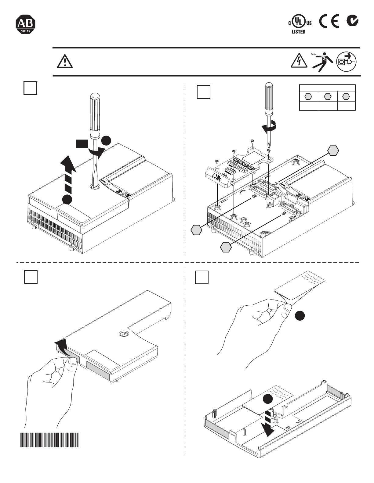
WARNING: To prevent electrical shock, disconnect from power source before
installing or servicing. Install in a suitable enclosure. Keep free from contaminants.
25U6
IND. CONT. EQ.
N223
1
I/O Port Compatibility*
7 8 9
ok ok ok
* only one 150-SM6 per controller
90°
2
0.45 Nm
(4 lb-in)
1
7
2
8
9
3
PN-164974
DIR 10000152879 (Version 01)
Publication 150-IN053B-EN-E
Printed in U.S.A.
4
1
2
Page 2
5
1
2
1
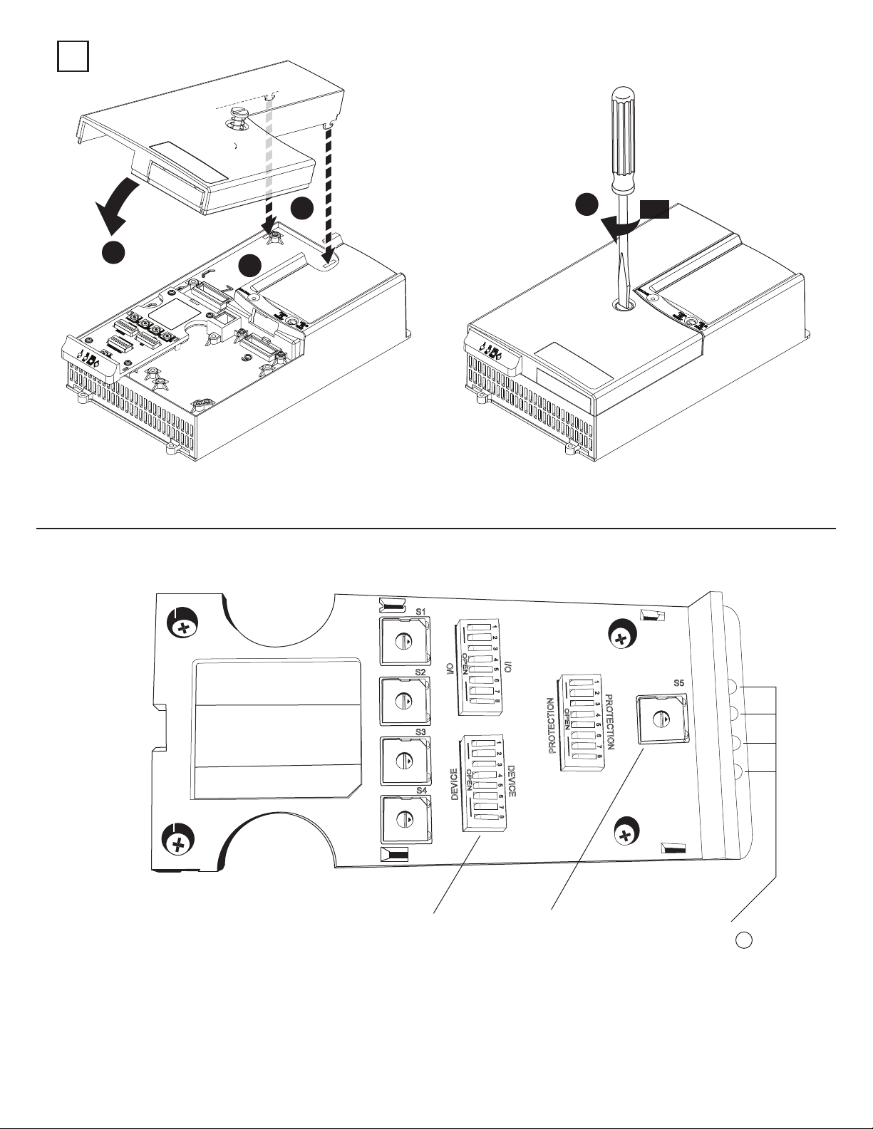
DIP Switch and Rotary Switch Locations
CAT.
150-SM6
SMC-50 PARAMETER CONFIGURATION
S1 Initial Torque
S2 Current Limit
S3 Ramp Time
S4 Stop Time
S5 Motor FLC
MFC LOC MFG DATE
FACxx yy/mm/dd
SER.
A
2
S1
D
C
E
B
A
F
0
9
1
8
2
7
3
6
4
5
S2
D
C
E
B
A
F
0
9
1
8
2
7
3
6
4
5
S3
D
C
E
B
A
F
0
9
1
8
2
7
3
6
4
5
S4
D
C
E
B
A
F
0
9
1
8
2
7
3
6
4
5
OPEN
I/O
OPEN
DEVICE
1 2 3 4 5 6 7 8
I/O
1 2 3 4 5 6 7 8
OPEN
1 2 3 4 5 6 7 8
PROTECTION
DEVICE
90°
PROTECTION
9
S5
D
C
E
B
A
F
0
1
8
2
7
3
6
4
5
DIP
Switch
Rotary
Switch
Diagnostic LEDs 1
1) For details regarding the operation and meaning of the Diagnostic LEDs refer to the SMC-50 User Manual 150-UM011_-EN-P.
PN-164974
DIR 10000152879 (Version 01)
Publication 150-IN053B-EN-E
(2)
Page 3

150-SM6 Switch Position Identification:
The following defines the functions of the 5 Rotary Switches:
S1 = Initial Torque Configuration:
Rotary Switch S1 Position Setting Resulting Initial Torque Value (in % Motor Torque)
S2 = Current Limit Configuration:
Rotary Switch S2 Position Setting Resulting Current Limit Value (in % Motor FLC)
S3 = Ramp Time Configuration- Starting:
Rotary Switch S3 Position Setting Starting Ramp Time (in Seconds)
0 10
1 16
2 22
3 28
4 34
5 40
6 46
7 52
8 58
9 64
A 70 (Default)
B 76
C 82
D 88
E 94
F 100
0 200
1 220
2 240
3 260
4 280
5 300
6 320
7 340
8 360 (Default)
9 380
A 400
B 420
C 440
D 460
E 480
F 500
0 0.1
1 2
2 4
3 6
4 8
5 10 (Default)
6 12
7 14
8 16
9 18
A 20
B 22
C 24
D 26
E 28
F
30
S4 = Stop Time Configuration:
Rotary Switch S4 Position Setting Stop Time (in Seconds 1 )
0 Coast to Stop (Default)
1 2
2 4
3 6
4 8
5 10
6 12
7 14
8 16
9 18
A 20
B 22
C 24
D 26
E 28
F 30
1) When the “Braking” STOP MODE is selected (Device Configuration Bank Switch #3 and #4) the controller multiplies the selected “Stop Time” by 10.
Refer to Device Configuration Switch Bank.
PN-164974
DIR 10000152879 (Version 01)
Publication 150-IN053B-EN-E
(3)
Page 4

S5 = Motor FLC (Full Load Current) Configuration:
Rotary Switch S5 Position Setting % of Controller’s Max FLC
0 40 (Default)
1 44
2 48
3 52
4 56
5 60
6 64
7 68
8 72
9 76
A 80
B 84
C 88
D 92
E 96
F 100
(1) (2)
(1) Since a set of switches do not provide the resolution to enter all possible Motor FLC combinations like a keypad, Switch S5 allows you to configure the
Motor’s FLC in the SMC50 by using a percent (%) of the controllers raed (e.g 90A, 110A, 140A, 180A, etc) FLC.
-
Example: For a 60A motor and a 90A controller, the % of Controller’s max FLC for 60A would be 64% of 90A (57.6A) or switch position 6.
(2) To determine the S5 switch setting for an inside the delta motor configuration use the following 2 equations:
Step 1
Motor Nameplate
:
FLC
1.73
X
Step 2
:
X
SMC - 50
X100
S5 Switch
Setting
Controller Rating
Example:
Step 1:
Step 2
100A
1.73
:
57.8 A
90A
57.8A
X100
S5 = Position 6
64 %
NOTE:
1) If the calculated value doesn’t match a switch position use the previous (lower percent) switch setting
2) The inside the delta motor configuration can be selected using Parameter 44 (Motor Connection) or automatically during a controller Tuning process.
The following defines the functions of the 3 banks of On/Off 8-switch DIP switches. Each of the 3 banks is defined by
a high level functional name (e.g. Device, I/O and Protection) with each switch having a unique function.
Device Configuration Bank (0=OPEN):
Switch Number #1 #2 #3 #4 #5 #6 #7 #8
Start Mode
PN-164974
DIR 10000152879 (Version 01)
Publication 150-IN053B-EN-E
Linear Speed Accel (Default) 0 0
(1)(2)
Stop Mode
Energy Saver
Braking Current
Linear Speed Decel (Default) 0 0
Current Limit 0 1
Soft Start 1 0
Pump Start 1 1
Soft Stop 0 1
Braking 1 0
Pump Stop 1 1
Enable 1
Disable (Default) 0
50% 0 0 0
100% 0 0 1
150% 0 1 0
200%(Default) 0 1 1
250% 1 0 0
300% 1 0 1
350% 1 1 0
400% 1 1 1
(4)
Page 5

(1) When the "Stop Mode" is configured as a) "Linear Speed Decel", b) "Soft Stop" or c) "Pump Stop" and the "Stop Time" (Rotary Switch S4) is set to 0 a “Coast”
to stop will result. A non-zero “Stop Time” value for the 3 previously listed “Stop Modes” defines the time to stop period based on that specific configurati
on.
(2) If the "Stop Mode" is configured as "Braking" then the "Stop Time" setting (Rotary Switch S4) is used to select either the "Automatic Zero Speed Detection"
method ("Stop Time" set to 0) or the "Timed Brake" method ("Stop Time" not set to 0).
NOTE:
a) With the “Automatic Zero Speed Detection” method, the controller applies the user selected “Braking Current” defined by the Device Configuration Switch
Bank, Switch #6, #7 & #8, senses a motor “Zero Speed” condition and automatically stops the braking process.
b) With the "Timed Brake" method the user selected “Braking Current” is applied for the user configured “Stop Time” regardless of the motor speed (i.e.
“Automatic Zero Speed Detection” disabled). The “Timed Brake” method can be used in applications where detecting zero speed is ineffectiv
e or when
braking the motor to a complete stop results in random overload trips. With this method, braking is applied for a fixed time equal to the “Stop Time” setting
(Rotary Switch S4) times 10. An ideal ‘Stop Time” setting can be accomplished by trial and error, but should always allow for some coast time. Setting the
“Stop Time” for to long can result in braking current to be applied to a stopped motor and will likely result in overload trips.
I/O Configuration
(1)
Bank (0=OPEN):
Switch Number #1 #2 #3 #4 #5 #6 #7 #8
Aux #1 Configuration
Aux #2 Configuration
Input #1
Input #2
Normal(default) 0 0
Up-to-Speed 0 1
Fault 1 0
Alarm 1 1
Normal 0 0
Up-to-Speed(default) 0 1
Fault 1 0
Alarm 1 1
Start/Coast(default) 0
Start/Stop Option 1
Stop Option(default) 0 0
Clear fault 0 1
Slow Speed 1 0
Fault 1 1
(1) The I/O configuration ability of the 150 - SM6 is limited to the Control Module’s standard I/O.
Protection Configuration Bank (0=OPEN):
NOTE:
For details concerning the operation of the Parameters controlled by the 150-SM6 Switch settings refer to the SMC-50 User Manual
(Publication 150-UM011_-EN-P) available from ab.com, Publications Library.
PN-164974
DIR 10000152879 (Version 01)
Publication 150-IN053B-EN-E
Switch Number #1 #2 #3 #4 #5 #6 #7 #8
Preset Protection Level
Disabled 0
Enable(Default) 1
Stall Fault
Enable(Default) 1
Disable 0
Phase Reversal Fault
Enable 1
Disable(Default) 0
OL Restart
Enable 1
Disable(Default) 0
OL Enable
Enable(Default) 1
Disable 0
Trip Class
10(Default) 0 0
15 0 1
20 1 0
30 1 1
(5)
Page 6

PN-164974
DIR 10000152879 (Version 01)
Publication 150-IN053B-EN-E
Printed in U.S.A.
 Loading...