

Page 1
SMC-50 PTC, Ground and Current Feedback Option Module
Installation Instructions
(Cat 150-SM2)
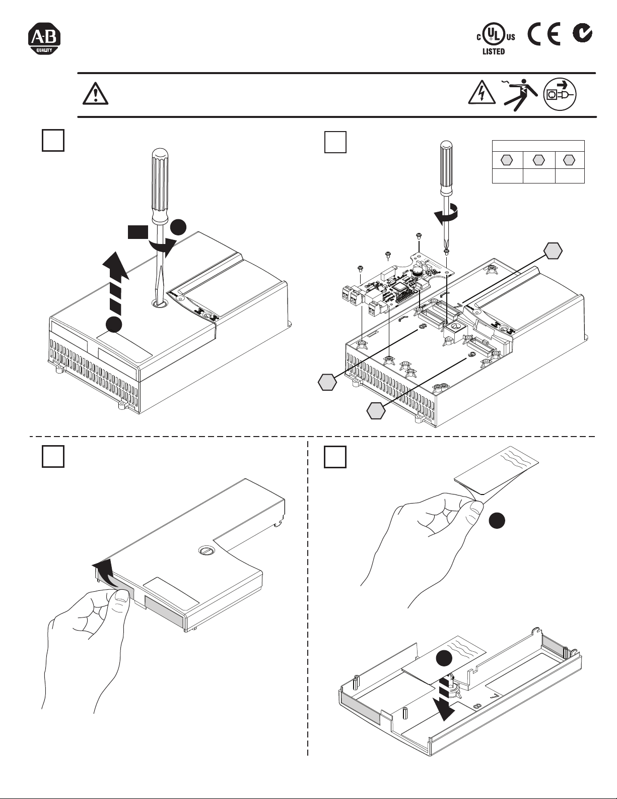
WARNING: To prevent electrical shock, disconnect from power source before
installing or servicing. Install in a suitable enclosure. Keep free from contaminants.
25U6
IND. CONT. EQ.
N223
1
90°
2
0.45 Nm
(4 lb-in)
1
Port Compatibility*
7 8 9
ok ok
*only one 150-SM2 per controller
7
2
8
9
3
PN-164973
DIR 10000152877 (Version 02)
Publication 150-IN051C-EN-E
Printed in U.S.A.
4
1
2
Page 2
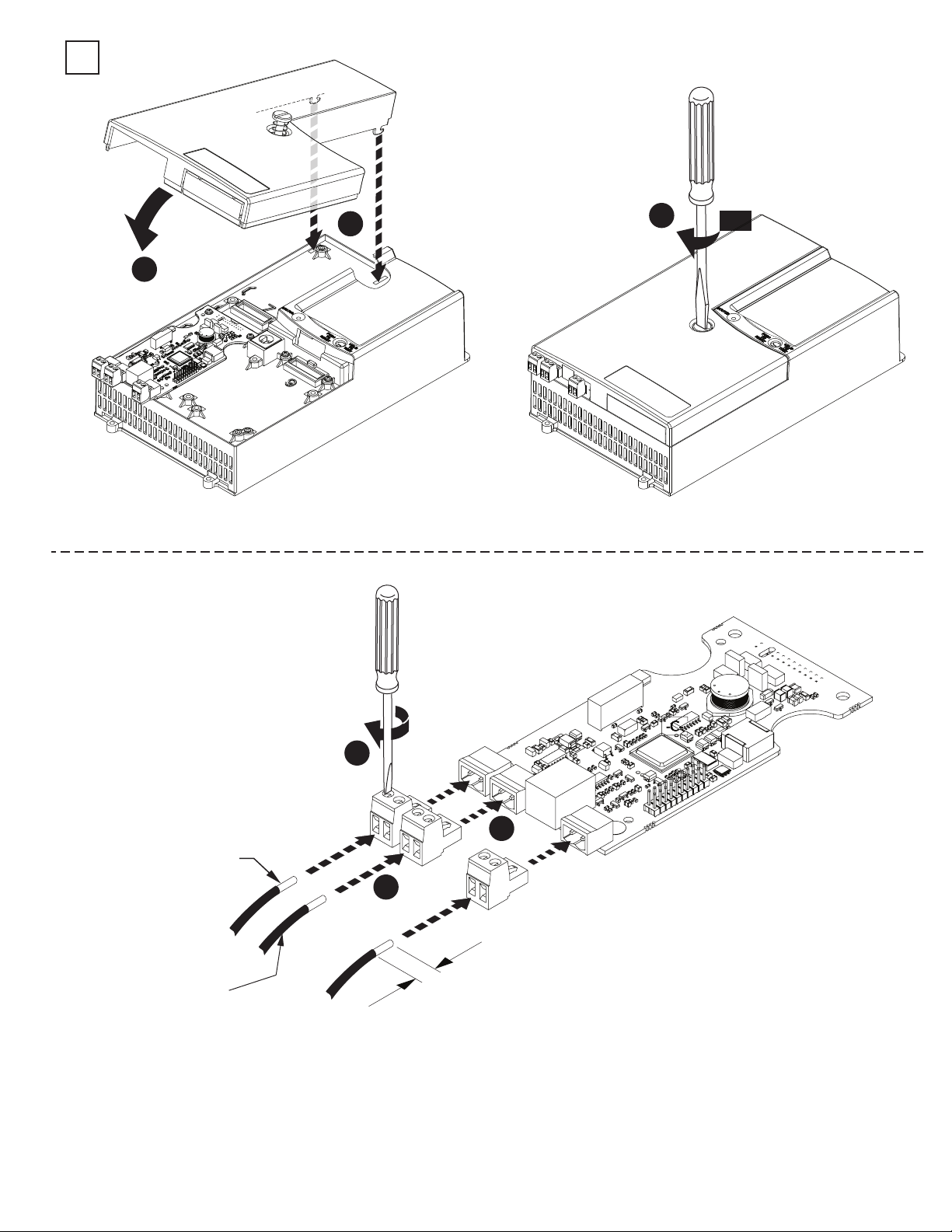
5
1
3
90°
2
0.2 - 2.5 mm
(#24 - #14 AWG)
SHIELDED
CABLE
0.2 - 2.5 mm
(#24 - #14 AWG)
SHIELDED
CABLE
NOTE:
When installed in control module port number 7 the orientation of the module is rotated 180°
PN-164973
DIR 10000152877 (Version 02)
Publication 150-IN051C-EN-E
0.8 Nm
(7 lb-in)
3
TB2
TB3
2
TB2
TB3
TB4
1
TB4
2
2
7.0 mm
(0.27 in)
(2)
Page 3
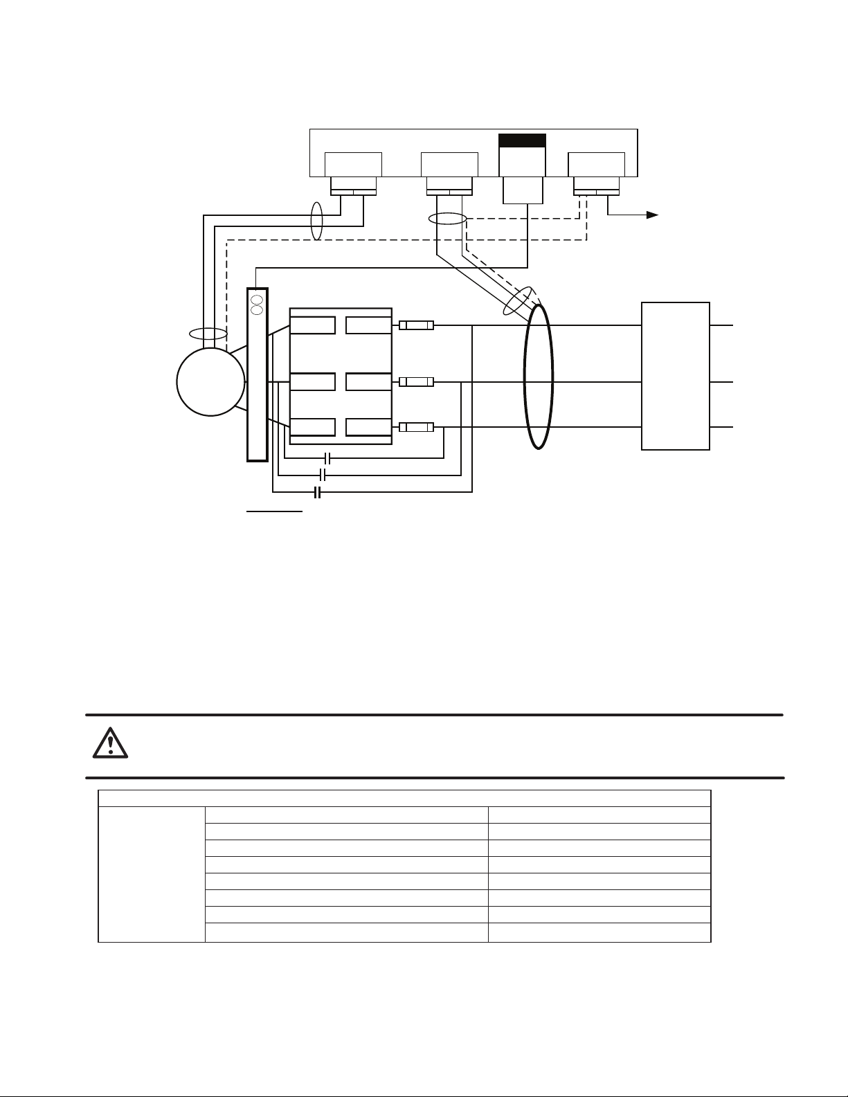
Field Wiring Terminal Identification
Motor PTC
Sensor
Cable
(1)
M
(1)
150-SM2
TB2
TB2
12
Shield
825-MCMxx Cable
T1/2
L1/1
(1)(2)
TB3
TB3
12
W
h
RG25U
Female
RG25U
Male
S
h
i
B
e
l
l
a
d
c
i
k
t
e
Fast-acting
SMC-50
T2/4
825-MCMxx 1 2
T3/6
Footnotes
(1) Customer Supplied
(2) The 825-MCMxxx can be used with or without an external bypass contactor. If an external bypass
contactor is used then the 825-MCMxxx must be installed in order to use current based motor protection
features including the motor overload feature. Cable length is 3 meters. Only the cable provided with the
825-MCMXXX is compatible with the 150-SM2.
(3) The 825-CBCT core balance sensor mounts separately from the SMC-50 and must be placed within
3 meters of it. When connecting the 825-CBCT ground fault sensor the secondary of the CT must be
shorted until connection to the 150-SM2 module is complete.
(4) Refer to the User Manual for additional bypass configurations (e.g. emergency run off bypass) and
application considerations.
L2/3
L3/5
External Bypass
SCR fuses
Optional
(1)(4)
(1)
825-CBCT Ground
Fault Core Balance
Shield
Sensor
TB4
TB4
To Control Module
Terminal #3
Ground
Circuit
Branch
Protection
(1)
(1) (3)
PTC Sensor Specifications
WARNING: The ground fault sensing feature of the SMC-50 is intended for monitoring purposes only and not as a
ground fault circuit interrupter for personnel protection as defined in Article 100 of the NEC and has not been
evaluated to UL 1053.
Response Resistance
Reset Resistance
Short-Circuit Trip Resistance
PTC Input Ratings
NOTE:
For additional information refer to the SMC-50 User Manual (150-UM011_-EN-P) available from
ab.com, Publications Library.
PN-164973
DIR 10000152877 (Version 02)
Publication 150-IN051C-EN-E
Max. Voltage at PTC Terminals (R = 4 kΩ)
Max. Voltage at PTC Terminals (R = open)
Max. No. of Sensors (Connected in Series)
Max. Cold Resistance of PTC Sensor Chain
Response Time
Electrical Ratings
3400 Ω ± 150 Ω
1600 Ω ± 100 Ω
25 Ω ± 10 Ω
PTC
PTC
< 7.5V
30V
6
1600 Ω
800 ms
(3)
Page 4

PN-164973
DIR 10000152877 (Version 02)
Publication 150-IN051C-EN-E
Printed in U.S.A.
 Loading...