

Page 1

User Manual
Combination Generator Control Module
Catalog Number 1407-CGCM
Page 2
Important User Information
IMPORTANT
Solid-state equipment has operational characteristics differing from those of electromechanical equipment. Safety
Guidelines for the Application, Installation and Maintenance of Solid State Controls (publication SGI-1.1
your local Rockwell Automation® sales office or online at http://www.rockwellautomation.com/literature/
important differences between solid-state equipment and hard-wired electromechanical devices. Because of this difference,
and also because of the wide variety of uses for solid-state equipment, all persons responsible for applying this equipment
must satisfy themselves that each intended application of this equipment is acceptable.
In no event will Rockwell Automation, Inc. be responsible or liable for indirect or consequential damages resulting from the
use or application of this equipment.
The examples and diagrams in this manual are included solely for illustrative purposes. Because of the many variables and
requirements associated with any particular installation, Rockwell Automation, Inc. cannot assume responsibility or
liability for actual use based on the examples and diagrams.
No patent liability is assumed by Rockwell Automation, Inc. with respect to use of information, circuits, equipment, or
software described in this manual.
Reproduction of the contents of this manual, in whole or in part, without written permission of Rockwell Automation,
Inc., is prohibited.
Throughout this manual, when necessary, we use notes to make you aware of safety considerations.
available from
) describes some
WARNING: Identifies information about practices or circumstances that can cause an explosion in a hazardous environment,
which may lead to personal injury or death, property damage, or economic loss.
ATTENTION: Identifies information about practices or circumstances that can lead to personal injury or death, property
damage, or economic loss. Attentions help you identify a hazard, avoid a hazard, and recognize the consequence.
SHOCK HAZARD: Labels may be on or inside the equipment, for example, a drive or motor, to alert people that dangerous
voltage may be present.
BURN HAZARD: Labels may be on or inside the equipment, for example, a drive or motor, to alert people that surfaces may
reach dangerous temperatures.
Identifies information that is critical for successful application and understanding of the product.
Allen-Bradley, Rockwell Software, Rockwell Automation, and TechConnect are trademarks of Rockwell Automation, Inc.
Trademarks not belonging to Rockwell Automation are property of their respective companies.
Page 3
Summary of Changes
This manual contains new and updated information. Changes throughout this
revision are marked by change bars, as shown to the right of this paragraph.
New and Updated Information
This table contains the changes made to this revision.
Topic Page
Updated label on the dimension diagrams 14
Updated wire temperature rating 15
Updated chassis ground wire requirements 20
Added Cross Current Compensation entity parameters to the
Generator Current Sensing table
Added Load Share entity parameters to the Metering table 205
Updated the Zone 2 Certification information in the Agency
Certifications table
198
206
Rockwell Automation Publication 1407-UM001G-EN-P - April 2013 3
Page 4

Summary of Changes
Notes:
4 Rockwell Automation Publication 1407-UM001G-EN-P - April 2013
Page 5

Table of Contents
Preface
General Information
Installation
CGCM Unit Operation
CGCM Unit Configuration
Additional Resources . . . . . . . . . . . . . . . . . . . . . . . . . . . . . . . . . . . . . . . . . . . . . . 7
Chapter 1
Introduction . . . . . . . . . . . . . . . . . . . . . . . . . . . . . . . . . . . . . . . . . . . . . . . . . . . . . 9
Functions . . . . . . . . . . . . . . . . . . . . . . . . . . . . . . . . . . . . . . . . . . . . . . . . . . . . . . . . 9
Chapter 2
Mounting Requirements . . . . . . . . . . . . . . . . . . . . . . . . . . . . . . . . . . . . . . . . . . 13
Electrical Connections. . . . . . . . . . . . . . . . . . . . . . . . . . . . . . . . . . . . . . . . . . . . 15
Chapter 3
Inputs and Outputs . . . . . . . . . . . . . . . . . . . . . . . . . . . . . . . . . . . . . . . . . . . . . . 38
Communication . . . . . . . . . . . . . . . . . . . . . . . . . . . . . . . . . . . . . . . . . . . . . . . . . 42
Operational Functions. . . . . . . . . . . . . . . . . . . . . . . . . . . . . . . . . . . . . . . . . . . . 43
Chapter 4
Introduction . . . . . . . . . . . . . . . . . . . . . . . . . . . . . . . . . . . . . . . . . . . . . . . . . . . . 71
Overview of the Configuration Process. . . . . . . . . . . . . . . . . . . . . . . . . . . . . 71
Preparation . . . . . . . . . . . . . . . . . . . . . . . . . . . . . . . . . . . . . . . . . . . . . . . . . . . . . . 71
Create a New Module in the ControlLogix Controller . . . . . . . . . . . . . . 72
Device Setup. . . . . . . . . . . . . . . . . . . . . . . . . . . . . . . . . . . . . . . . . . . . . . . . . . . . . 74
CGCM Unit Startup
CGCM Unit Software Interface
Troubleshooting
Time Over-current
Characteristic Curves
Chapter 5
Introduction . . . . . . . . . . . . . . . . . . . . . . . . . . . . . . . . . . . . . . . . . . . . . . . . . . . . 105
Safety . . . . . . . . . . . . . . . . . . . . . . . . . . . . . . . . . . . . . . . . . . . . . . . . . . . . . . . . . . 105
Recommended Equipment . . . . . . . . . . . . . . . . . . . . . . . . . . . . . . . . . . . . . . . 106
Recommended Start-up Procedure. . . . . . . . . . . . . . . . . . . . . . . . . . . . . . . . 107
Document Configuration Parameter and Wiring Changes. . . . . . . . . . 123
Chapter 6
Introduction . . . . . . . . . . . . . . . . . . . . . . . . . . . . . . . . . . . . . . . . . . . . . . . . . . . . 125
CGCM Unit User Program Interface . . . . . . . . . . . . . . . . . . . . . . . . . . . . . 126
CGCM Unit Data Tables. . . . . . . . . . . . . . . . . . . . . . . . . . . . . . . . . . . . . . . . 130
Chapter 7
. . . . . . . . . . . . . . . . . . . . . . . . . . . . . . . . . . . . . . . . . . . . . . . . . . . . . . . . . . . . . . . . 151
Appendix A
General. . . . . . . . . . . . . . . . . . . . . . . . . . . . . . . . . . . . . . . . . . . . . . . . . . . . . . . . . 165
Curve Specifications. . . . . . . . . . . . . . . . . . . . . . . . . . . . . . . . . . . . . . . . . . . . . 165
Time Over-current Characteristic Curve Graphs. . . . . . . . . . . . . . . . . . . 166
Rockwell Automation Publication 1407-UM001G-EN-P - April 2013 5
Page 6

Table of Contents
Appendix B
CGCM Unit Math Models
Additional ControlNet Network
Information
Specifications
Detailed CGCM Unit Tag
Descriptions
Introduction . . . . . . . . . . . . . . . . . . . . . . . . . . . . . . . . . . . . . . . . . . . . . . . . . . . . 185
Synchronous Machine Terminal Voltage Transducer and Load
Compensator Model. . . . . . . . . . . . . . . . . . . . . . . . . . . . . . . . . . . . . . . . . . . . . 185
Voltage Regulator . . . . . . . . . . . . . . . . . . . . . . . . . . . . . . . . . . . . . . . . . . . . . . . 186
VAR/Power Factor Controller . . . . . . . . . . . . . . . . . . . . . . . . . . . . . . . . . . . 187
Limiters . . . . . . . . . . . . . . . . . . . . . . . . . . . . . . . . . . . . . . . . . . . . . . . . . . . . . . . . 187
V/Hz Limiter . . . . . . . . . . . . . . . . . . . . . . . . . . . . . . . . . . . . . . . . . . . . . . . . . . . 189
Soft Start Control . . . . . . . . . . . . . . . . . . . . . . . . . . . . . . . . . . . . . . . . . . . . . . . 190
Field Current Regulator . . . . . . . . . . . . . . . . . . . . . . . . . . . . . . . . . . . . . . . . . 191
Appendix C
ControlNet Application Objects . . . . . . . . . . . . . . . . . . . . . . . . . . . . . . . . . 193
Appendix D
. . . . . . . . . . . . . . . . . . . . . . . . . . . . . . . . . . . . . . . . . . . . . . . . . . . . . . . . . . . . . . . . 197
Appendix E
Generator Parameters and Configuration Status . . . . . . . . . . . . . . . . . . . 207
General Excitation Control Modes . . . . . . . . . . . . . . . . . . . . . . . . . . . . . . . 208
AVR Mode . . . . . . . . . . . . . . . . . . . . . . . . . . . . . . . . . . . . . . . . . . . . . . . . . . . . . 209
FCR Mode . . . . . . . . . . . . . . . . . . . . . . . . . . . . . . . . . . . . . . . . . . . . . . . . . . . . . 210
Power Factor Mode. . . . . . . . . . . . . . . . . . . . . . . . . . . . . . . . . . . . . . . . . . . . . . 211
VAR Mode . . . . . . . . . . . . . . . . . . . . . . . . . . . . . . . . . . . . . . . . . . . . . . . . . . . . . 212
Excitation Control Features . . . . . . . . . . . . . . . . . . . . . . . . . . . . . . . . . . . . . . 213
Protection . . . . . . . . . . . . . . . . . . . . . . . . . . . . . . . . . . . . . . . . . . . . . . . . . . . . . . 216
Synchronizing. . . . . . . . . . . . . . . . . . . . . . . . . . . . . . . . . . . . . . . . . . . . . . . . . . . 222
Load Sharing. . . . . . . . . . . . . . . . . . . . . . . . . . . . . . . . . . . . . . . . . . . . . . . . . . . . 225
Metering . . . . . . . . . . . . . . . . . . . . . . . . . . . . . . . . . . . . . . . . . . . . . . . . . . . . . . . 227
Redundancy . . . . . . . . . . . . . . . . . . . . . . . . . . . . . . . . . . . . . . . . . . . . . . . . . . . . 229
Appendix F
Configuration Record
Generator Information . . . . . . . . . . . . . . . . . . . . . . . . . . . . . . . . . . . . . . . . . . 231
Worksheet
Index
6 Rockwell Automation Publication 1407-UM001G-EN-P - April 2013
. . . . . . . . . . . . . . . . . . . . . . . . . . . . . . . . . . . . . . . . . . . . . . . . . . . . . . . . . . . . . . . . 239
Page 7
Preface
The information in this manual applies to the 1407-CGCM module, Series C,
Revision D, with host firmware revision 4.9 and ControlNet firmware revision
1.11. The manual notes differences with earlier versions of the product where
they occur.
Additional Resources
These documents contain additional information concerning related products
from Rockwell Automation.
Resource Description
Safety Guidelines for the Application,
Installation and Maintenance of Solid State
Controls, publication SGI-1.1
ControlNet Coax Media Planning and
Installation, publication CNET-IN002
Logix5000 Controllers Common Procedures,
publication 1756-PM001
CGCM Release Notes, publication 1407-RN001
Industrial Automation Wiring and Grounding
Guidelines, publication 1770.4.1.
Product Certifications website,
http://www.ab.com
Describes some important differences between
solid-state equipment and hard-wired
electromechanical devices.
Provides installation procedures for the
ControlNet network.
Provides information about RSLogix 5000
software.
Provides information on compatible RSLogix
5000 software versions and ControlLogix
controller firmware revisions.
Provides general guidelines for installing a
Rockwell Automation industrial system.
Provides declarations of conformity, certificates,
and other certification details.
You can view or download publications at http://www.rockwellautomation.com/
literature/. To order paper copies of technical documentation, contact your local
Allen-Bradley distributor or Rockwell Automation sales representative.
Rockwell Automation Publication 1407-UM001G-EN-P - April 2013 7
Page 8

Preface
Notes:
8 Rockwell Automation Publication 1407-UM001G-EN-P - April 2013
Page 9

General Information
Chapter
1
Introduction
Functions
The Combination Generator Control Module (CGCM unit) is a
microprocessor-based control and protection device. The CGCM unit is
designed to integrate with a Logix family programmable controller to provide
generator control, protection and synchronization functions. Programmability of
system parameters, regulation settings, and protective functions enable the
CGCM unit to be used in a wide range of applications.
The following sections outline the functions of the unit.
Generator Regulation and Control Functions
This list contains the generator regulation and control functions:
• Four excitation control modes
• Automatic voltage regulation (AVR)
• Manual or field current regulation (FCR)
• Power factor (PF)
• Reactive power (VAR)
• Soft start voltage buildup with an adjustable ramp in AVR and FCR
control modes
• Over-excitation (OEL) and under-excitation (UEL) limiting in AVR,
VAR , and PF contr ol modes
• Under-frequency compensation (Volts/Hertz)
• Line drop compensation
• Auto-tracking between operating modes and between redundant CGCM
units
• Automatic transfer to a back-up CGCM unit in redundant systems
• Generator paralleling with reactive droop compensation or cross-current
(reactive differential) compensation
• Generator paralleling with real power load sharing
• Synchronizing for one or two circuit breakers
Rockwell Automation Publication 1407-UM001G-EN-P - April 2013 9
Page 10

Chapter 1 General Information
Generator Protection Functions
This list contains the generator protection functions:
• Loss of excitation current (40)
• Over-excitation voltage (59F)
• Generator over-voltage (59)
• Generator under-voltage (27)
• Loss of sensing (60FL)
• Loss of permanent magnet generator
(PMG/Excitation power) (27)
• Reverse VAR (40Q)
• Over-frequency (81O)
• Under-frequency (81U)
• Reverse power (32R)
• Rotating diode monitor
• Phase rotation error (47)
• Generator over-current (51)
Metering Functions
This list contains the metering functions:
• Vo l t a g e
• Current
• Fre que ncy
• Real Power
• Apparent Power
• Reactive Power
• Power Factor
• Real Energy (kWh)
• Apparent Energ y (kVAh)
• Reactive Energy (kVARh)
• Controller Excitation Current and Voltage
• Diode Monitor Ripple Level
• Load Share Error
• Synchronization Parameters
10 Rockwell Automation Publication 1407-UM001G-EN-P - April 2013
Page 11

General Information Chapter 1
Inputs
This list contains the inputs for the CGCM unit:
• Single-phase or 3-phase true rms generator voltage sensing
• Single-phase dual bus or 3-phase single bus voltage sensing
• 3-phase generator current sensing (1 or 5 A nominal)
• Single-phase cross current loop 1 or 5 A current transformer (CT) input
• Auxiliary ±10V DC input providing remote control of the setpoints
• DC power input
Outputs
This list contains the outputs for the CGCM unit:
• Pulse-width modulated output power stage rated at 15 A
• Discrete redundancy relay output
• Discrete fault output driver
• Load sharing connection for use with the Allen-Bradley Line
Synchronization Module (1402-LSM) or compatible hardware
Communication Interfaces
The CGCM unit has these three communication ports:
• Redundant ControlNet connector
• RS-232 port for dedicated communication with a redundant CGCM
• RS-232 port for factory configuration and test (not for customer use)
Rockwell Automation Publication 1407-UM001G-EN-P - April 2013 11
Page 12

Chapter 1 General Information
Notes:
12 Rockwell Automation Publication 1407-UM001G-EN-P - April 2013
Page 13
Installation
Chapter
2
Mounting Requirements
This equipment is intended for use in a Pollution Degree 2 Industrial
Environment, in over-voltage Category II applications (as defined by IEC
publication 60664-1). Because the units contain a heat sink, they must be
mounted vertically. Any other mounting angle reduces the heat dissipation
capabilities of the units, possibly leading to premature failure of critical
components. The unit can be mounted anywhere that the ambient temperature
does not exceed the rated environmental conditions or clearance requirements.
The clearance requirements for the CGCM unit are:
• 63.5 mm (2.5 in.) of clearance is required on both sides of the unit when
mounted.
• 101.6 mm (4 in.) of clearance is required above and below the unit when
mounted.
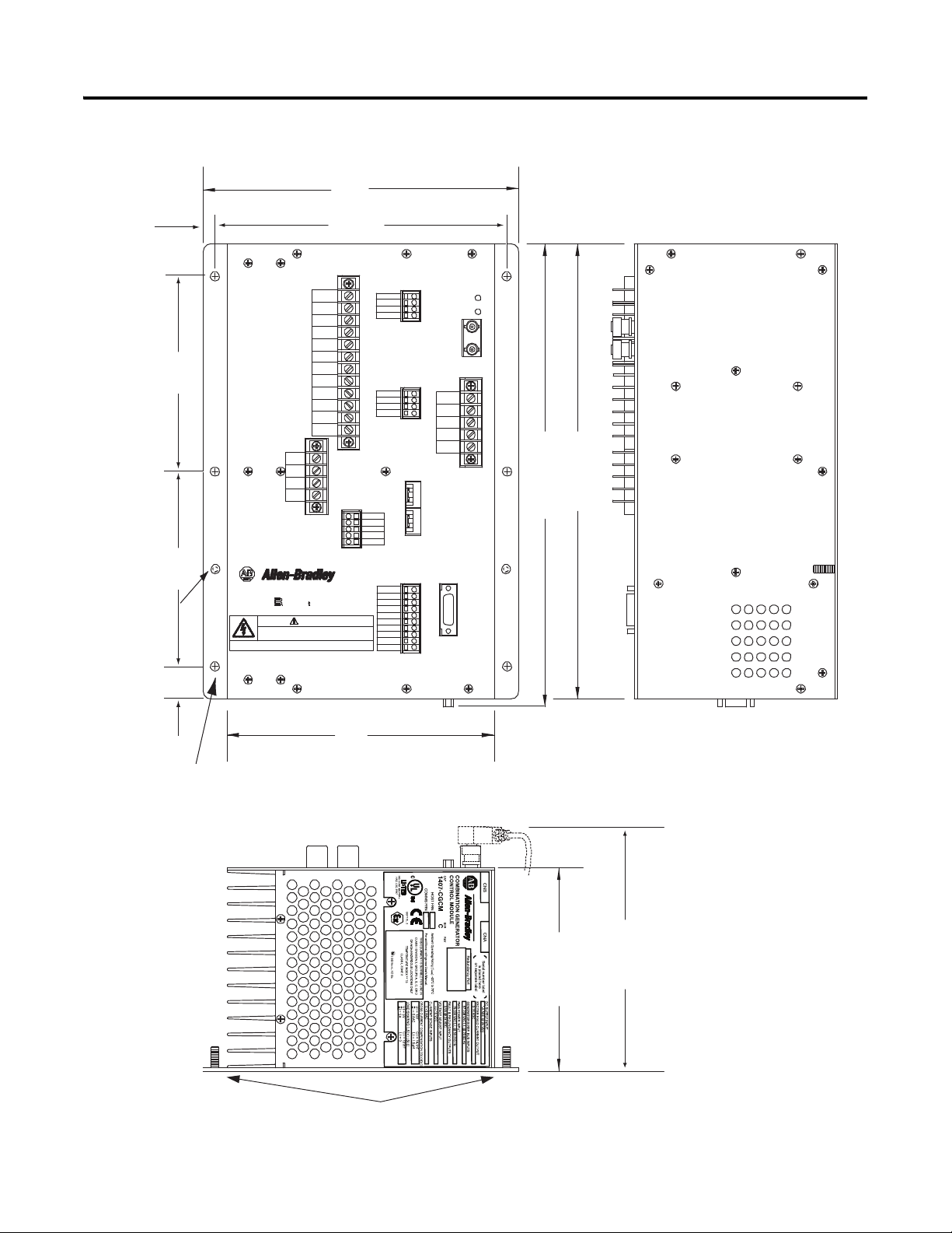
Overall dimensions for the unit are shown in CGCM Unit Overall Dimensions
on page 14.
WARNING: Explosion Hazard
• Substitution of components can impair suitability for Class I, Division 2.
• Do not replace components or disconnect equipment unless power has been switched
off or the area is known to be non-hazardous.
• Do not connect or disconnect components unless power has been switched off or the
area is known to be non-hazardous.
• This product must be installed in an enclosure. All cables connected to the product
must remain in the enclosure or be protected by conduit or other means.
• All wiring must comply with N.E.C. article 501-4(b).
Rockwell Automation Publication 1407-UM001G-EN-P - April 2013 13
Page 14
CNA
CNB
Manufactured by
aB
R
BAT (-)
BAT (+)
DANGER
elrle Es ricc
4
5
ID (+) 1A
ID (+) 5A
ID (-)
I3 (+) 1A
I3 (+) 5A
I3 (-)
I2 (+) 1A
I2 (+) 5A
I2 (-)
I1 (+) 1A
I1 (+) 5A
I1 (-)
TB5
TB6
TB3
SHLD 2
SHLD 2
EXC (+)
EXC (-)
TB2
Combination
Generator
Control Module
TB4
FLT
RD RLY
CH GND
TB7
ControlNet
Address
TB1
PMG A
PMG B
PMG C
SHLD 1
SHLD 1
V Bus A
V Bus B
V Bus C
V Bus N
V Gen A
V Gen B
V Gen C
V Gen N
VREF (+)
VREF (-)
SHLD 3
SHLD 3
A-COM
EX-D (+)
EX-D (-)
LS (+)
LS (-)
SHLD 4
Factory
Test
Port
247.7
(9.75)
355.6
(14.00)
363
(~14.3)
1/4 - 20 Ground
Stud (2 Places)
7.14 (0.281) DIA
Mounting Hole
(6 Places)
209.6
(8.25)
25.4
(1.00)
152.4
(6.00)
152.4
(6.00)
228.6
(9.00)
9.7
(0.38)
159.0
(6.26)
190.0
(~7.5)
Notes:
1. Weight = 7.7 kg (17 lb)
2. Dimensions are in millimeters (inches)
Ground Studs
HAZARDOUS VOLTAGE CAN CAUSE SHOCK, BURNS, OR DEATH.
1) DISCONNECT AND LOCK OUT ALL POWER SOURCES AND,
2) SHORT ALL CURRENT TRANSFORMER SECONDARIES BEFORE SERVICING.
MORE THAN ONE LIVE CIRCUIT. SEE DIAGRAM.
ADVERTISSMENT: CET EQUIPEMENT RENFERME PLUSIEURS CIRCUITS SOUS TENSION, V OIR LE SCHEMA
DEMKO 13 ATEX 1202591U
MADE IN U.S.A.
1201 SOUTH SECOND ST.
MILWAUKEE, WISCONSIN
53204
AEx nC IIC T3, Ex nL IIC T3 Gc X
Chapter 2 Installation
Figure 1 - CGCM Unit Overall Dimensions
14 Rockwell Automation Publication 1407-UM001G-EN-P - April 2013
Page 15
Installation Chapter 2
Electrical Connections
The CGCM unit’s connections are dependent on the application and excitation
scheme. All inputs or outputs cannot be used in a given installation. Incorrect
wiring can result in damage to the unit.
Connect the CGCM unit’s terminals with copper wire rated for a minimum of
°
600V. General appliance wire rated for minimum temperatures of 105
°
F) is acceptable. All wire must be copper. Select circuit conductors based on good
C (221
design practice.
The wire gauge range listed in the Te rm i na l B l oc k L ab el D e sc ri p ti on
table
indicates the physical capabilities of the connector.
The CGCM unit’s terminals are on the front, bottom, and right panel of the unit.
The nine-pin connector on the bottom of the unit is used for communication
between CGCM units in a redundant system. Suggested torque for terminal
screws is 1 N•m (9 lb•in).
Refer to pages 17
…34 for typical connection diagrams.
Terminals to be used as landing points for shielded wires are provided on several
terminal strips. Shield terminals with the same name are internally connected
together but are not connected to protective earth or any internal unit circuitry.
Table 1 - Terminal Block Label Description
Terminal Block Wire Gauge
TB1
TB2 SHLD2 Shield 2 landing points are tied together but are not connected internally to protective earth or
Range
2.6…2.1 mm
(10…12 AWG)
Label Description
2
PMG A Phase A excitation power supply
PMG B Phase B excitation power supply (three phase only)
PMG C Phase C excitation power supply
SHLD1 Shield 1 landing points are tied together but are not connected internally to protective earth or
SHLD1
SHLD2
EXC(-) Excitation output negative
EXC(+) Excitation output positive
other unit circuitry
other unit circuitry
Rockwell Automation Publication 1407-UM001G-EN-P - April 2013 15
Page 16
Chapter 2 Installation
Table 1 - Terminal Block Label Description
Terminal Block Wire Gauge
Label Description
Range
2
TB3
2.6…2.1 mm
(10…12 AWG)
ID(+)1 A 1 A cross-current compensation CT input
ID(+)5 A 5 A cross-current compensation CT input
ID(-) Cross-current compensation CT common input
I3(+)1 A 1 A phase C CT input
I3(+)5 A 5 A phase C CT input
I3(-) Phase C CT common input
I2(+)1 A 1 A phase B CT input
I2(+)5 A 5 A phase B CT input
I2(-) Phase B CT common input
I1(+)1 A 1 A phase A CT input
I1(+)5 A 1 A phase A CT input
I1(-) Phase A CT common input
TB4
1.6…1.0 mm
(14…18 AWG)
2
BAT(+) 24V DC control power input
BAT(-) 24V DC control power return
FLT Open collector fault output
RD RLY Open collector output for redundancy relay
CH GND Chassis ground
TB5 V Gen A Phase A generator voltage input
V Gen B Phase B generator voltage input
V Gen C Phase C generator voltage input
V Gen N Neutral generator voltage input
TB6 V Bus A
V Bus B
Phase A bus voltage input
Phase B bus voltage input
(1)
(1)
V Bus C Phase C bus voltage input
V Bus N Neutral bus voltage input
2
TB7
1.6…1.0 mm
(14…18 AWG)
VREF(+) Remote setpoint adjust input
VREF(-) Remote setpoint adjust input return
SHLD3 Shield 3 landing points are tied together but are not connected internally to protective earth or
SHLD3
other unit circuitry
A-COM Analog common
EX-D(+) Excitation enable input
EX-D(-) Excitation enable return
LS(+) Real power load sharing input
LS(-) Real power load sharing return
SHLD4 Shield 4 landing point is not connected internally to protective earth or other unit circuitry
(1) When used in a dual breaker configuration, Bus A voltage input is wired from V Bus A to V Bus N and Bus B is wired from V Bus B to V Bus N.
16 Rockwell Automation Publication 1407-UM001G-EN-P - April 2013
Page 17
Installation Chapter 2
TB1
PMG A
PMG B
PMG C
SHL D 1
SHL D 1
PMG
TB1
PMG A
PMG B
PMG C
SHLD 1
SHLD 1
Fuse
G
AC
B
Excitation Power
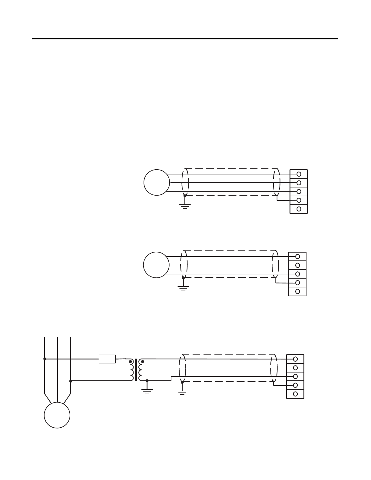
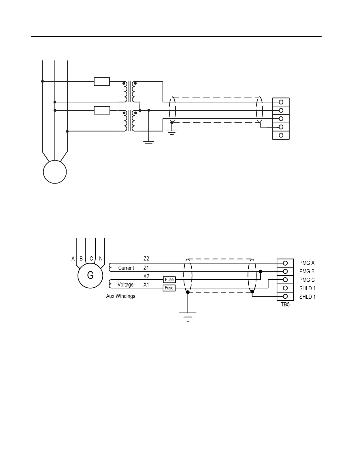
Excitation power is wired to the PMG terminals, whether connected to the
generator output (Shunt Excited) or to a PMG. Connect shunt excited inputs
with a voltage transformer (VT).
PMG inputs are on TB1 and are labeled PMG A, PMG B, and PMG C,
illustrating their respective phase relationships. Single-phase excitation power
must be connected to terminals PMG A and PMG C. Twisted, shielded cabling is
required for the PMG inputs.
Refer to the wiring diagrams below.
Figure 2 - Excitation Power Connections, 3-phase PMG
Figure 3 - Excitation Power Connections, Single-phase PMG
PMG A
PMG
Figure 4 - Excitation Power Connections, Single-phase Shunt
Rockwell Automation Publication 1407-UM001G-EN-P - April 2013 17
PMG B
PMG C
SHLD 1
SHLD 1
TB1
Page 18
Chapter 2 Installation
TB1
PMG A
PMG B
PMG C
SHLD 1
SHLD 1
Fuse
Fuse
G
AC
B
TIP
Figure 5 - Excitation Power Connections, 3-phase Shunt
Figure 6 - Excitation Power Connections, AREP Generator
This diagram is based on a Leroy Somer 300 kW AREP (auxiliary winding
regulation excitation principle) machine. Details can differ on other
machines.
18 Rockwell Automation Publication 1407-UM001G-EN-P - April 2013
Page 19
Installation Chapter 2
TB2
Shld2
Shld2
EXC (-)
EXC (+)
Exciter field
Exciter voltage
connections
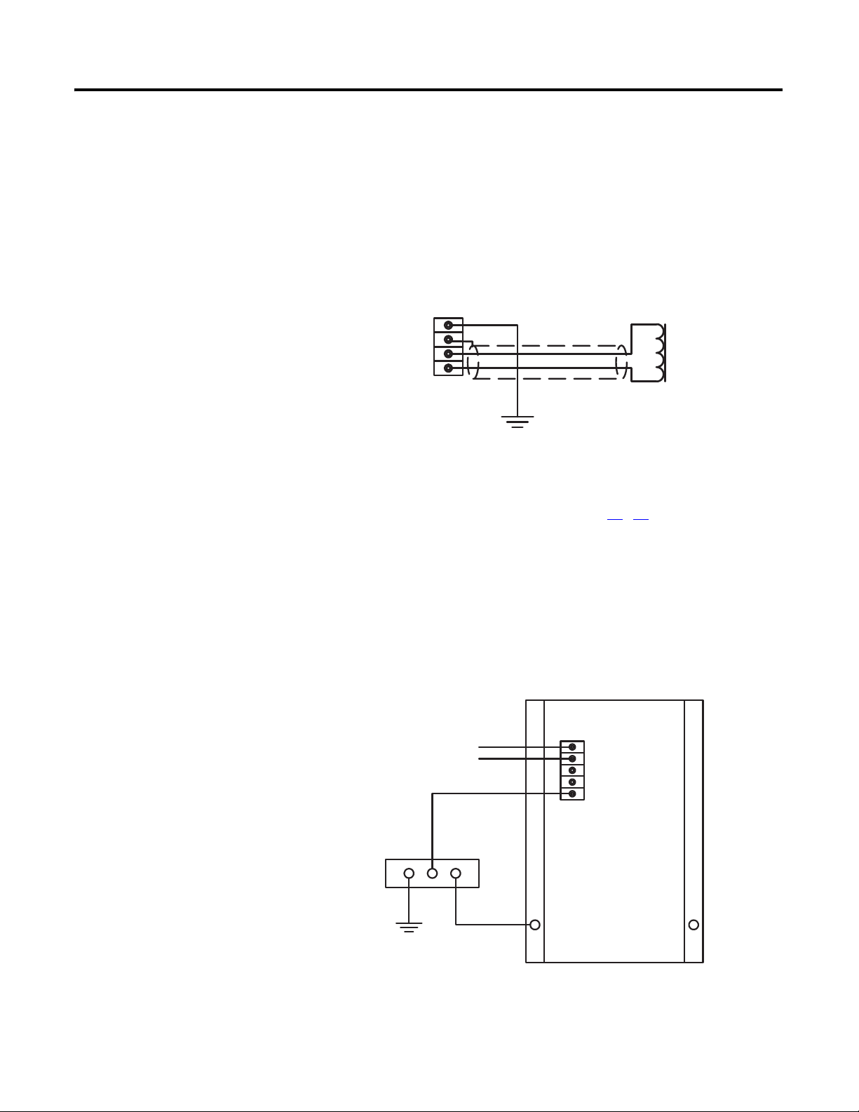
Excitation Output
The excitation outputs are on TB2 and are labeled EXC(+) and EXC(-).
Twisted, shielded cabling is required for the excitation outputs.
Figure 7 - Excitation Output Connections, Non-redundant CGCM
When the redundancy function is used, three or four external flyback diodes in
series must be placed across the generator field winding.
Refer to the redundancy wiring diagrams on pages 31
…32.
Control Power
The 24V DC control power inputs are on TB4 and are labeled BAT(+) and
BAT(-).
Figure 8 - Control Power and Chassis Ground Connections
24 VDCControl
Power Source
Ground bus
Ground stud
Rockwell Automation Publication 1407-UM001G-EN-P - April 2013 19
BAT(+)
BAT(-)
FLT
RD RLY
CH GND
TB4
(typical)
CGCM
Page 20

Chapter 2 Installation
Chassis Ground
The terminal labeled CH GND, on TB4, is the chassis ground. Ground studs are
also provided on the lower part of the mounting flanges and are internally
connected to the CH GND terminal. Connect chassis ground to earth ground
2
with minimum 2.6 mm
(10 AWG) copper wire attached to either stud on the
lower part of either side of the unit and to the CH GND terminal with 1.6 mm
(14 AWG) copper wire. When installed in a system with other CGCM units, use
a separate lead to the ground bus from each unit.
AC Voltage and Current Sensing
The CGCM unit supports generator and bus voltage sensing and generator
current sensing.
Generator and Bus Voltage Sensing
2
CGCM units accept single-phase or 3-phase generator and bus voltage sensing
input with nominal voltages of 120 or 208V AC.
Refer to Terminal Block Label Description
on page 15 for possible wiring
configurations.
The terminals found on TB5 provide connections for generator voltage sensing
and are labeled V GEN A, V GEN B, V GEN C, and V GEN N. The terminals
found on TB6 provide connections for bus voltage sensing and are labeled V BUS
A, V BUS B, V BUS C, and V BUS N. The connection examples below show
typical connections for various generator and bus connection schemes.
The CGCM unit supports these generator connection schemes:
• Single-phase
• Delta or Two-transformer Open Delta
• Three-wire Wye
• Four-wire Wye
The CGCM supports these bus connection schemes:
• Single-phase
• Delta or Two-transformer Open Delta
• Three-wire Wye
• Four-wire Wye
• Dual Breaker, Single-phase only
20 Rockwell Automation Publication 1407-UM001G-EN-P - April 2013
Page 21

Installation Chapter 2
Generator Current Sensing
CGCM units provide 3-phase AC current sensing with provisions for 1 A and 5
A nominal sensing ranges. The inputs for 3-phase current sensing are on TB3.
The ID (+) and ID (-) terminals are used for systems connected in a cross-current
compensation system.
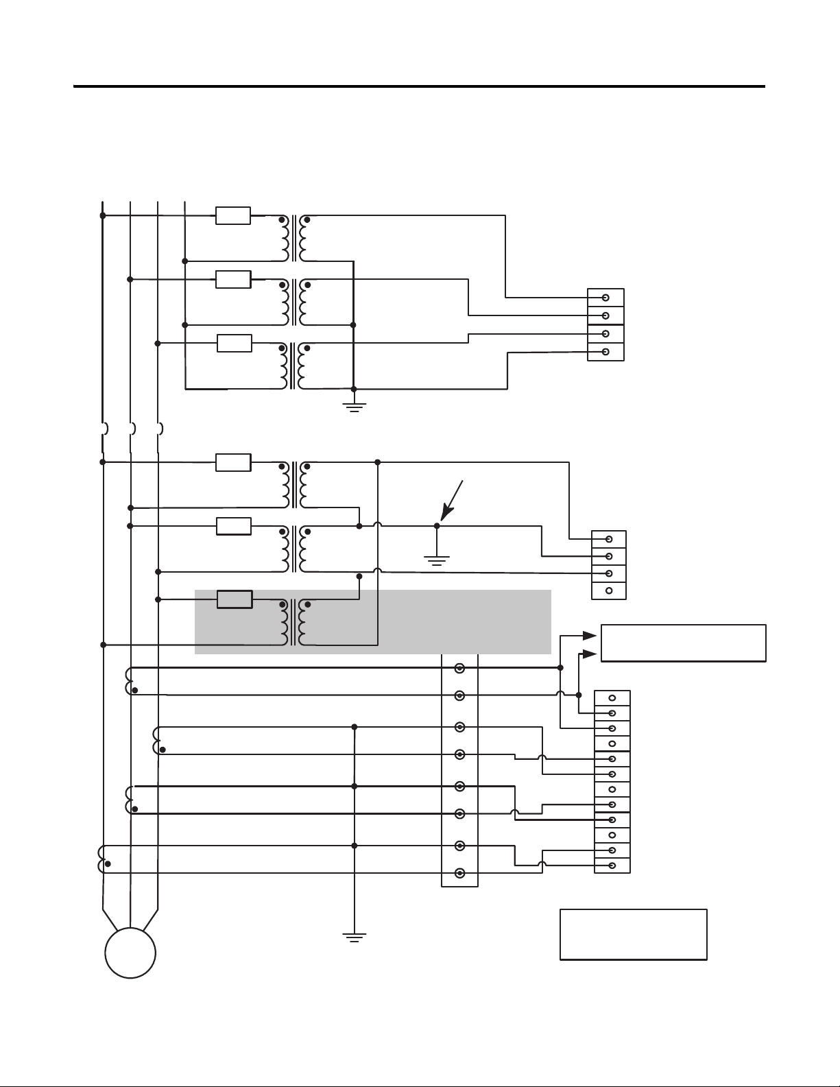
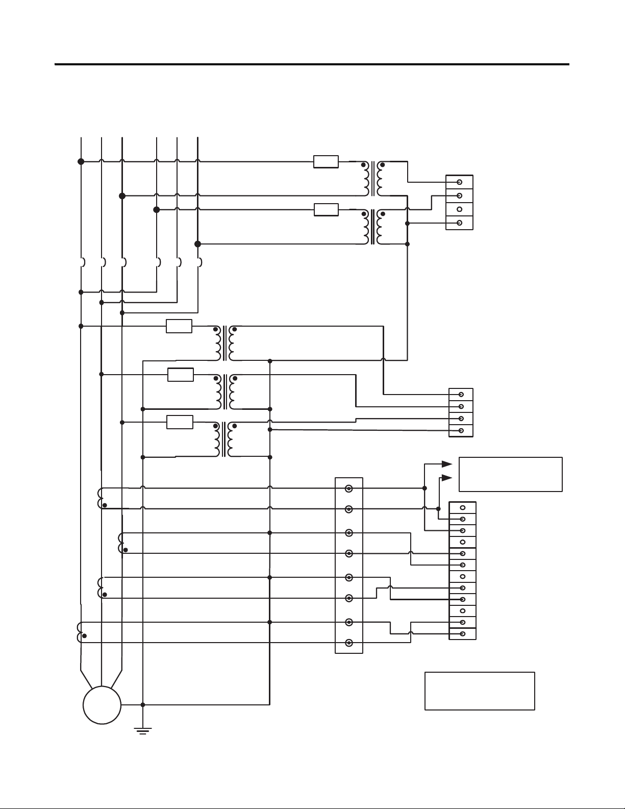
Voltage and Current Sensing Connection Examples
The following examples depict typical connections of voltage (also called
potential) transformer (VTs) and current transformers (CTs) to the CGCM unit
for various bus and generator power system configurations. These diagrams do
not show all connections to the CGCM unit, nor are they intended to show all
possible wiring combinations. For assistance in wiring a CGCM unit in a power
system configuration not shown below, please contact Rockwell Automation.
Rockwell Automation Publication 1407-UM001G-EN-P - April 2013 21
Page 22
L1
L2 L3
G
CB
TB 3
TB 6
VBus A
VBus B
VBus C
VBus N
TB 5
AC
B
Fuse
Optional
Ground
Optional
Ground
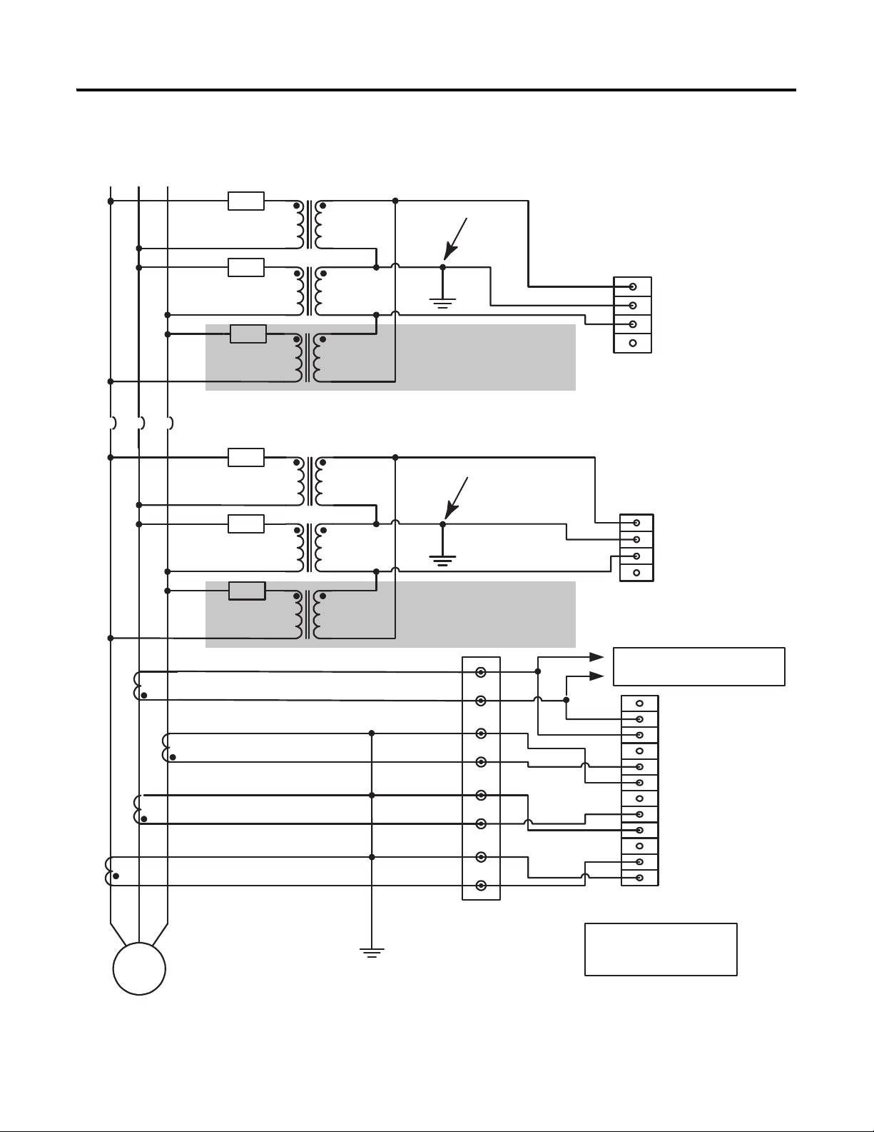
Use of a third potential
transformer is optional. The
CGCM unit can be connected
in either open or closed delta.
Use of a third potential
transformer is optional. The
CGCM unit can be connected
in either open or closed delta.
Fuse
Fuse
Fuse
Fuse
Fuse
VGen A
VGen B
VGen C
VGen N
To optional cross-current
reactive compensation loop.
Cross-current CT input
not required for parallel
droop operation.
ID(+) 1A
ID (+) 5A
ID (-)
I3 (+) 1A
I3 (+) 5A
I3 (-)
I2 (+) 1A
I2 (+) 5A
I2 (-)
I1 (+) 1A
I1 (+) 5A
I1 (-)
Customer Supplied CT
Shorting Switch or Test
Block
Chapter 2 Installation
Figure 9 - Voltage and Current Connection for Two (or three) Transformer Delta Bus
and Two (or three) Transformer Delta Generator System
22 Rockwell Automation Publication 1407-UM001G-EN-P - April 2013
Page 23
L1 NL2 L3
CB
N
Fuse
Fuse
Fuse
Fuse
Fuse
Fuse
G
AC
B
TB3
I1 (+) 5A
I1 (-)
ID (+) 5A
I3 (+) 5A
I2 (+) 5A
I2 (-)
I3 (-)
ID (-)
I1 (+) 1A
I2 (+) 1A
I3 (+) 1A
ID (+) 1A
TB6
VBus A
VBus B
VBus C
VBus N
TB5
VGen A
VGen B
VGen C
VGen N
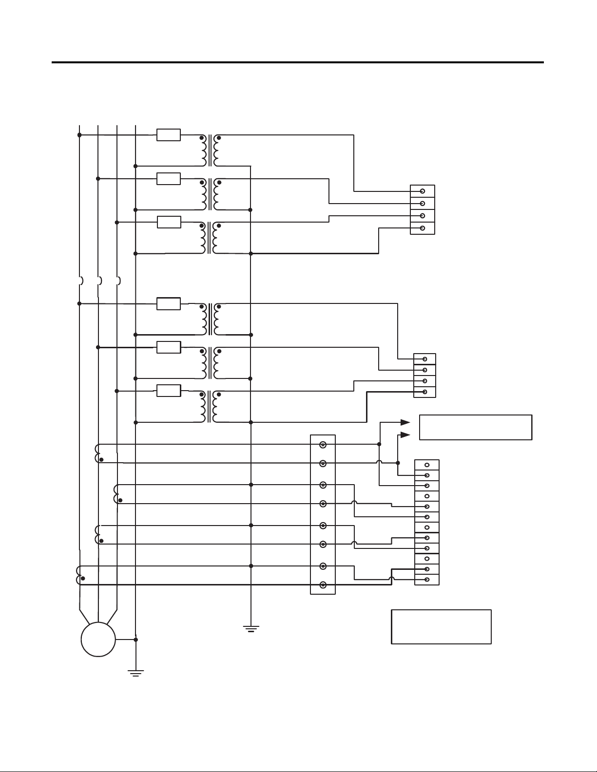
To optional cross-current
reactive compensation loop.
Customer Supplied CT
Shorting Switch or Test
Block
Cross-current CT input
not required for parallel
droop operation.
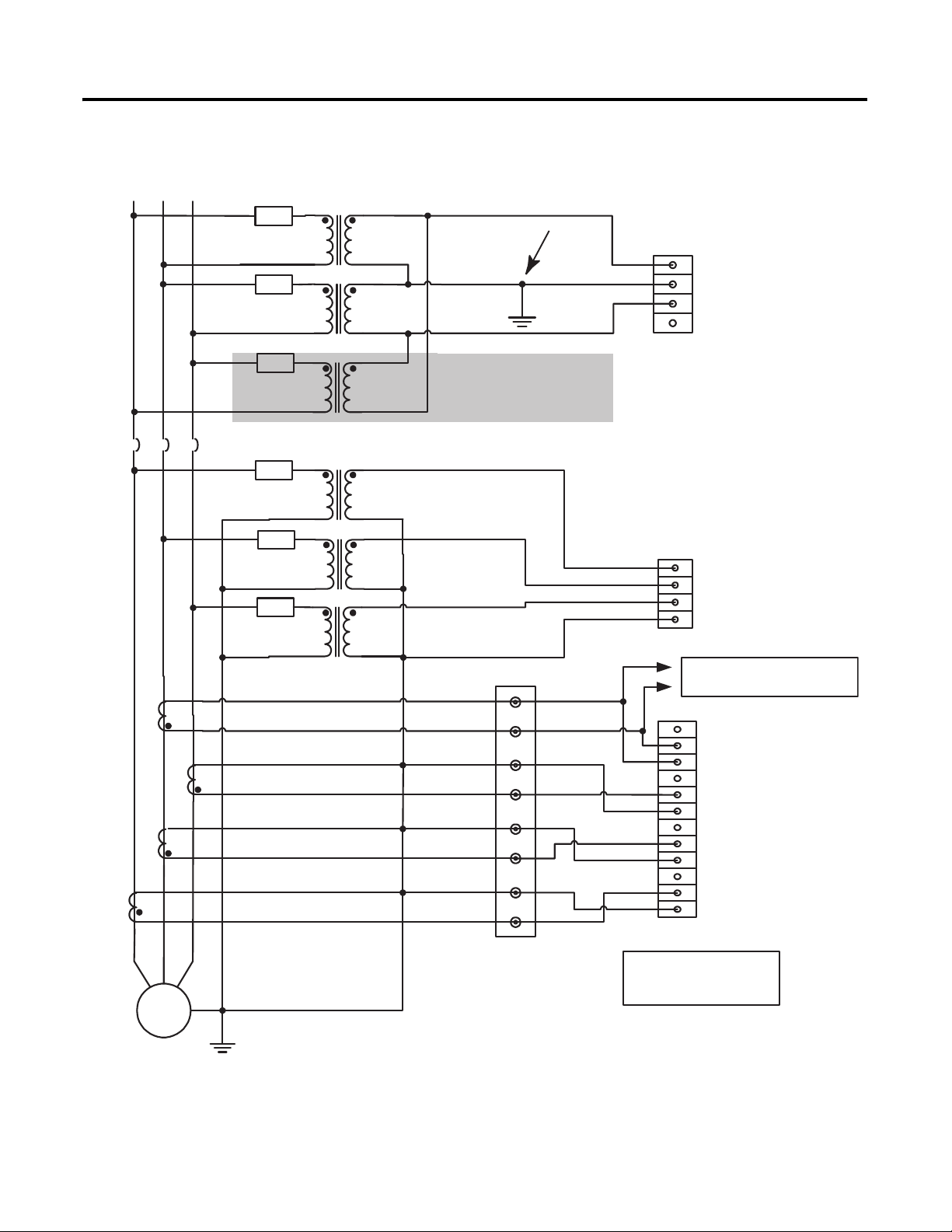
Installation Chapter 2
Figure 10 - Voltage and Current Connection for Four-wire Wye Bus and Four-wire
Wye Generator System with Grounded Neutral
Rockwell Automation Publication 1407-UM001G-EN-P - April 2013 23
Page 24
Chapter 2 Installation
L1 NL2 L3
G
CB
AC
B
Fus e
Fuse
Fuse
Fuse
Fuse
Fuse
TB3
I1 (+) 5A
I1 (-)
ID (+) 5A
I3 (+) 5A
I2 (+) 5A
I2 (-)
I3 (-)
ID ( -)
I1 (+) 1A
I2 (+) 1A
I3 (+) 1A
ID (+) 1A
TB 6
VBu s A
VBu s B
VBu s C
VBu s N
TB5
VGe n A
VGe n B
VGe n C
VGe n N
Customer Supplied CT
Shorting Switch or Test
Block
Cross-current CT input
not required for parallel
droop operations.
To optional cross-current
reactive compensation loop.
Optional
Ground
Use of a third potential
transformer is optional. The
CGCM unit can be connected
in either open or closed delta.
Figure 11 - Voltage and Current Connection for Four-wire Wye Bus and Two (or
three) Transformer Delta Generator System
24 Rockwell Automation Publication 1407-UM001G-EN-P - April 2013
Page 25
L1 L2 L3
G
CB
AC
B
Fuse
Fuse
Fuse
Fuse
Fuse
Fuse
N
TB3
I1 (+) 5 A
I1 (- )
ID (+) 5A
I3 (+) 5 A
I2 (+) 5 A
I3 (- )
ID (- )
I1 (+) 1 A
I2 (+) 1 A
I3 (+) 1 A
ID (+) 1A
TB 6
VBus A
VBus B
VBus C
VBus N
TB 5
V Gen A
VGe n B
V Gen C
V Gen N
I2 (- )
Optional
Ground
To optional cross-current
reactive compensation loop.
Customer Supplied CT
Shorting Switch or Test
Block
Cross-current CT input
not required for parallel
droop operation.
Use of a third potential
transformer is optional. The
CGCM unit can be connected
in either open or closed delta.
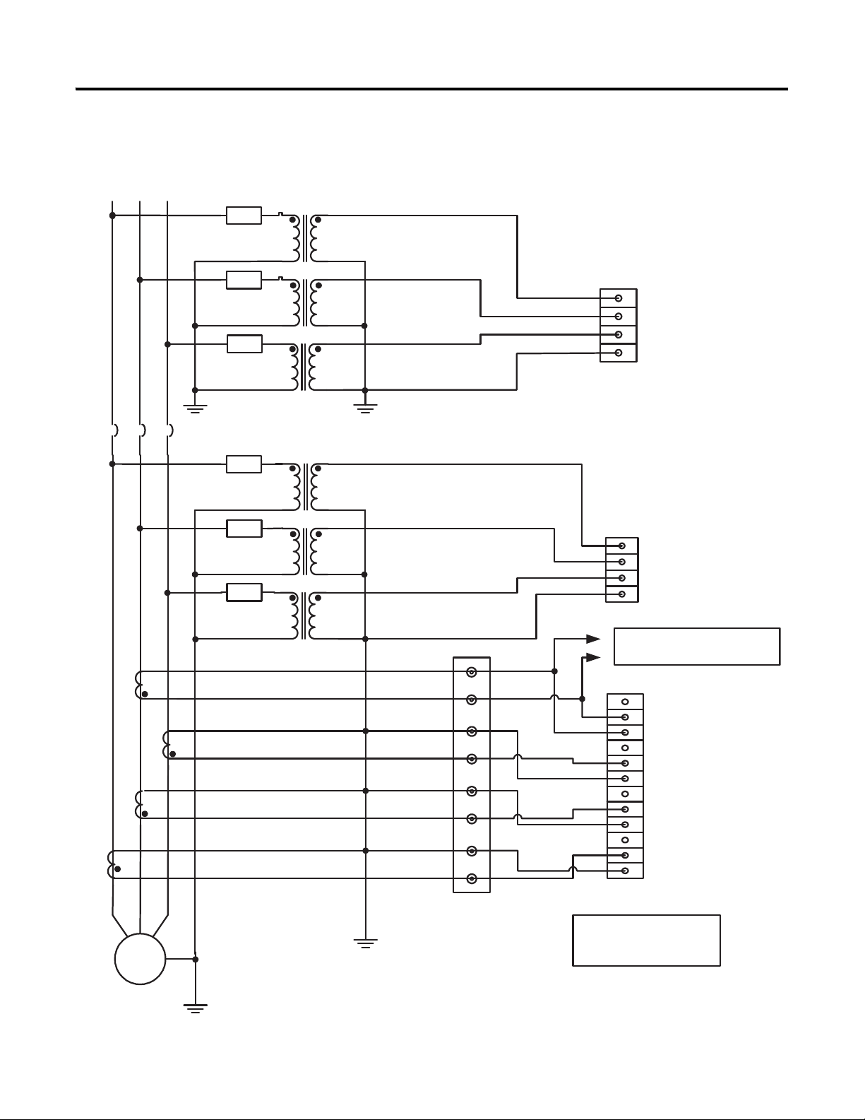
Installation Chapter 2
Figure 12 - Voltage and Current Connection for Two (or three) Transformer Delta
Bus and Four-wire Wye Generator System
Rockwell Automation Publication 1407-UM001G-EN-P - April 2013 25
Page 26
Chapter 2 Installation
L1 L2 L3
CB
N
Fuse
Fuse
Fuse
Fuse
Fuse
Fuse
G
AC
B
TB3
I1 ( +) 5 A
I1 ( -)
ID ( +) 5 A
I3 ( +) 5 A
I2 ( +) 5 A
I2 ( -)
I3 ( -)
ID (-)
I1 ( +) 1 A
I2 ( +) 1 A
I3 ( +) 1 A
ID ( +) 1 A
TB 6
VBus A
VBus B
VBus C
VBus N
TB5
VGen A
VGen B
VGen C
VGen N
Customer Supplied CT
Shorting Switch or Test
Block
Cross-current CT input
not required for parallel
droop operation.
To optional cross-current
reactive compensation loop.
Figure 13 - Voltage and Current Connection for Three-wire Wye Bus and Four-wire
Wye Generator System with Grounded Neutral
26 Rockwell Automation Publication 1407-UM001G-EN-P - April 2013
Page 27
Installation Chapter 2
L1 A L 2A L 3A
CB
Fus e
Fuse
CB
L1 B L 2B L 3B
Fuse
Fuse
Fus e
G
TB 3
I1 (+ ) 5A
I1 (-)
ID (+ ) 5A
I3 (+ ) 5A
I2 (+ ) 5A
I2 (-)
I3 (-)
ID (-)
I1 (+ ) 1A
I2 (+ ) 1A
I3 (+ ) 1A
ID (+ ) 1A
TB 6
VBus A
VBus B
VBus C
VBus N
TB 5
VGen A
VGen B
VGen C
VGen N
AC
B
Optional
Ground
To optional crosscurrent reactive
compensation loop.
Cross-current CT input
not required for parallel
droop operation.
Customer Supplied CT
Shorting Switch or Test
Block
Use of a third potential
transformer is optional. The
CGCM unit can be connected
in either open or closed delta.
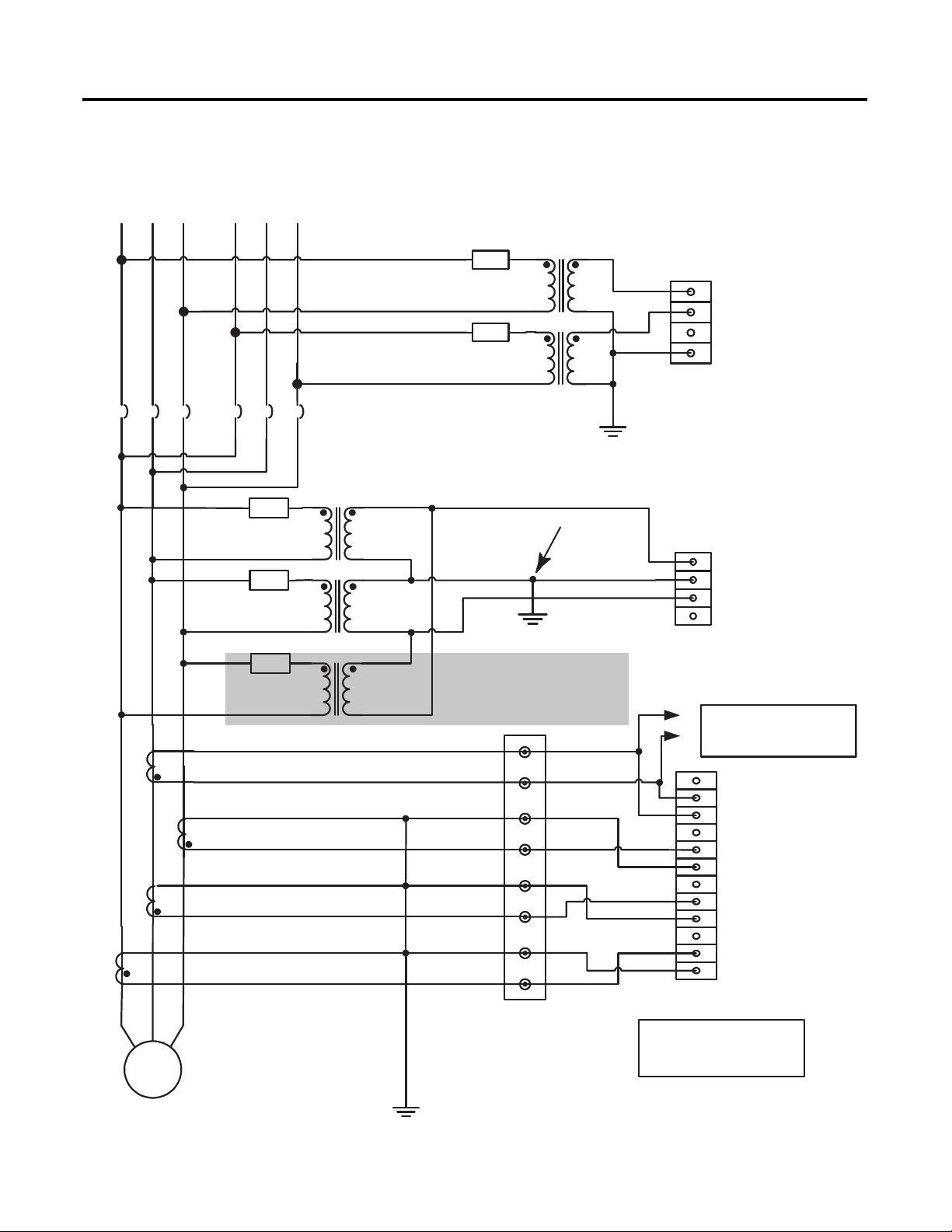
Figure 14 - Voltage and Current Connection for Dual Breaker Bus and Two (or three)
Transformer Delta Generator System
Rockwell Automation Publication 1407-UM001G-EN-P - April 2013 27
Page 28
Chapter 2 Installation
L1 A L2A L3 A
CB
Fuse
Fuse
Fuse
Fuse
Fuse
N
CB
L1B L2 B L3B
G
TB3
I1 (+ ) 5A
I1 (- )
ID (+ ) 5 A
I3 (+ ) 5A
I2 (+ ) 5A
I2 (- )
I3 (- )
ID (- )
I1 (+ ) 1A
I2 (+ ) 1A
I3 (+ ) 1A
ID (+ ) 1 A
TB6
VBus A
VBus B
VBus C
VBus N
TB5
VGen A
VGen B
VGen C
VGen N
AC
B
To optional crosscurrent reactive
compensation loop.
Cross-current CT input
not required for parallel
droop operation.
Customer Supplied CT
Shorting Switch or Test
Block
Figure 15 - Voltage and Current Connection for Dual Breaker Bus and Four-wire
Wye Generator System
28 Rockwell Automation Publication 1407-UM001G-EN-P - April 2013
Page 29
L1 L2 L3
CB
Fuse
Fuse
TB 6
VBus A
VBus B
VBus C
VBus N
TB5
VGen A
VGen B
VGen C
VGen N
G
AC
B
TB3
I1 (+) 5 A
I1 (-)
ID (+ ) 5 A
I3 (+) 5 A
I2 (+) 5 A
I2 (-)
I3 (-)
ID ( -)
I1 (+) 1 A
I2 (+) 1 A
I3 (+) 1 A
ID (+ ) 1 A
To optional cross-current
reactive compensation loop.
Cross-current CT input
not required for parallel
droop operation.
Customer Supplied CT
Shorting Switch or Test
Block
Installation Chapter 2
Figure 16 - Voltage and Current Connection for Single Phase Bus and Single-phase
Generator System
Rockwell Automation Publication 1407-UM001G-EN-P - April 2013 29
Page 30
Chapter 2 Installation
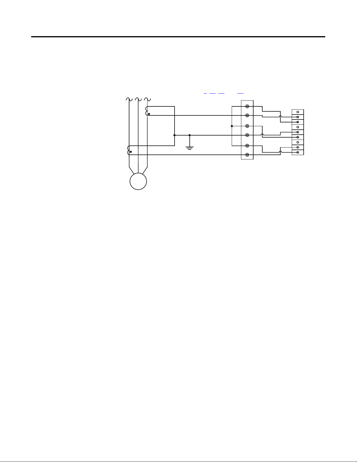
Figure 17 - Current Connections for 3-phase Delta Generator with Two CTs
The connections shown in this diagram can be used if only two CTs are available
in the generator circuit. Two CTs can be used only with a three-wire delta
generator. The circuit shown in this diagram can be substituted for the CT
connections shown in Figures 9
B
AC
, 11, 14, and 16.
Customer Supplied CT
Shorting Switch or Test
Block
TB 3
I3 (+) 1A
I3 (+) 5A
I3 (-)
I2 (+) 1A
I2 (+) 5A
I2 (-)
I1 (+) 1A
I1 (+) 5A
I1 (-)
G
Auxiliary Input
The auxiliary input is a +/- 10V DC input. The auxiliary input terminals are on
TB7 and are labeled VREF(+) and VREF(-). SHLD3 is provided for landing the
cable shield. Twisted, shielded cabling is required for the VREF connections.
Remote Excitation Enable Input
The remote excitation enable input is a 24V DC input. The remote excitation
enable input terminals are on TB7 and are labeled EX-D(+) and EX-D(-).
Discrete Outputs
There are two types of discrete outputs: fault relay outputs and redundancy relay
outputs.
30 Rockwell Automation Publication 1407-UM001G-EN-P - April 2013
Page 31

Installation Chapter 2
TB 6
VBus A
VBus B
VBus C
VBus N
TB6
VBus A
VBus B
VBus C
VBus N
Bus Voltage
Connections
TB5
VGen A
VGen B
VGen C
VGen N
TB 5
VGen A
VGen B
VGen C
VGen N
CGCM 1
CGCM 2
Generator
Voltage
Connections
Fault Relay Output
The fault relay output is an open-collector sinking output. The fault relay output
terminals are on TB4 and are labeled FLT. The following illustration shows a
typical connection.
Figure 18 - Typical Fault Relay Connection
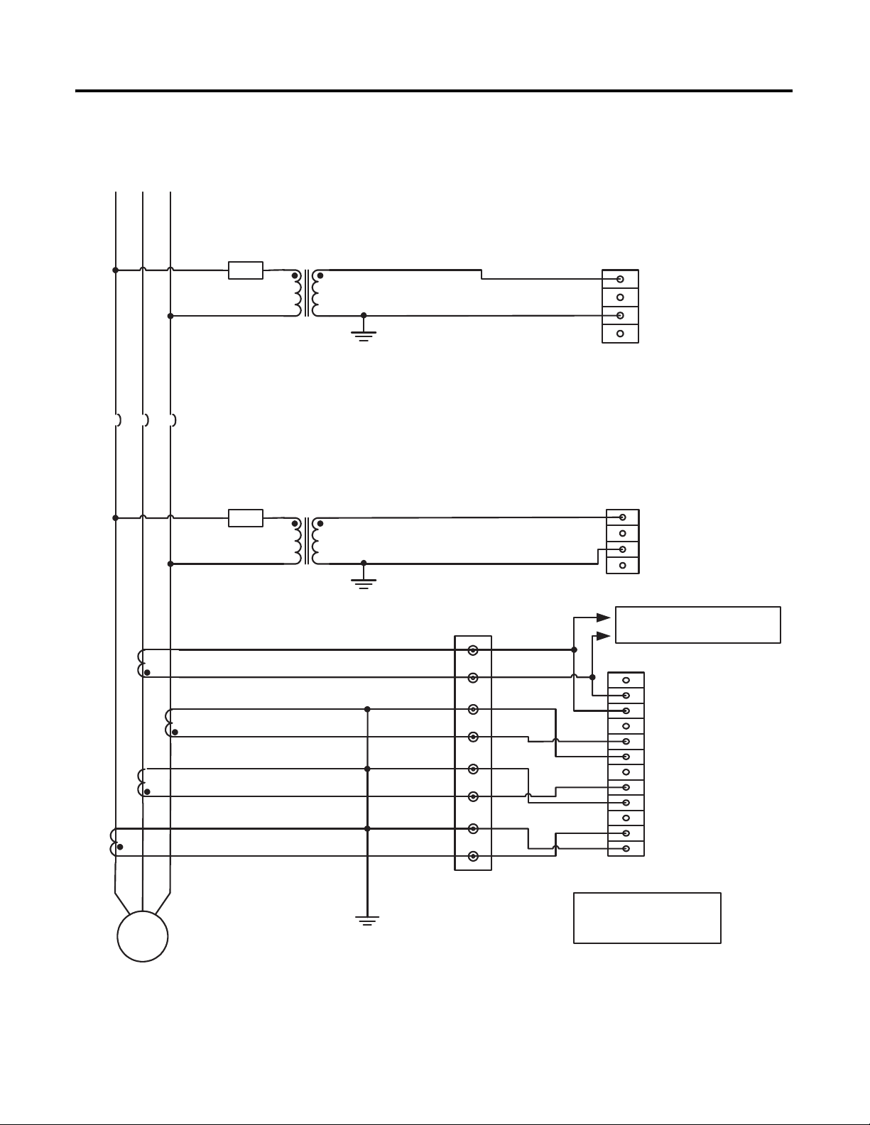
Redundancy Relay Output
The redundancy relay output is an open-collector sinking output. The
redundancy relay output terminals are on TB4 and are labeled RD RLY. The
following figures illustrate typical redundancy connections.
Figure 19 - Typical Redundancy Voltage Sensing Connection Diagram
Rockwell Automation Publication 1407-UM001G-EN-P - April 2013 31
Page 32

Chapter 2 Installation
TB3
I1 (+) 1A
I1 ( -)
I1 (+) 5A
TB 3
I1 (+) 1A
I1 (-)
I1 (+) 5A
Generator
Current
Connections
CGCM 1
CGCM 2
Typical connection for
one current input. Other
current inputs (including
the cross-current input)
should duplicate.
Customer
Supplied CT
Shorting Blocks
or Test Block
CGCM 1
CGCM 2
TB 2
Shld2
Shld2
EXC (-)
EXC (+)
TB 2
Exciter Voltage
Connections
Shld2
Shld2
EXC (-)
EXC (+)
TB4
TB4
BAT (+ )
BAT(-)
FLT
RD RLY
CH GND
BAT (+)
BAT (-)
FLT
RD RL Y
CH GND
User-provided
Relay
Exciter Field
Flyback Diodes
(3 - 4)
User-provided
Relay
Figure 20 - Typical Redundancy Current Sensing Connection Diagram
Figure 21 - Typical Redundancy Excitation Power Connection Diagram
PMG Voltage
Connections
TB 1
TB1
Figure 22 - Typical Redundancy Relay Connection Diagram
32 Rockwell Automation Publication 1407-UM001G-EN-P - April 2013
PMG A
PMG B
PMG C
Shield
Shield
PMG A
PMG B
PMG C
Shield
Shield
CGCM 1
CGCM 2
Page 33
Installation Chapter 2
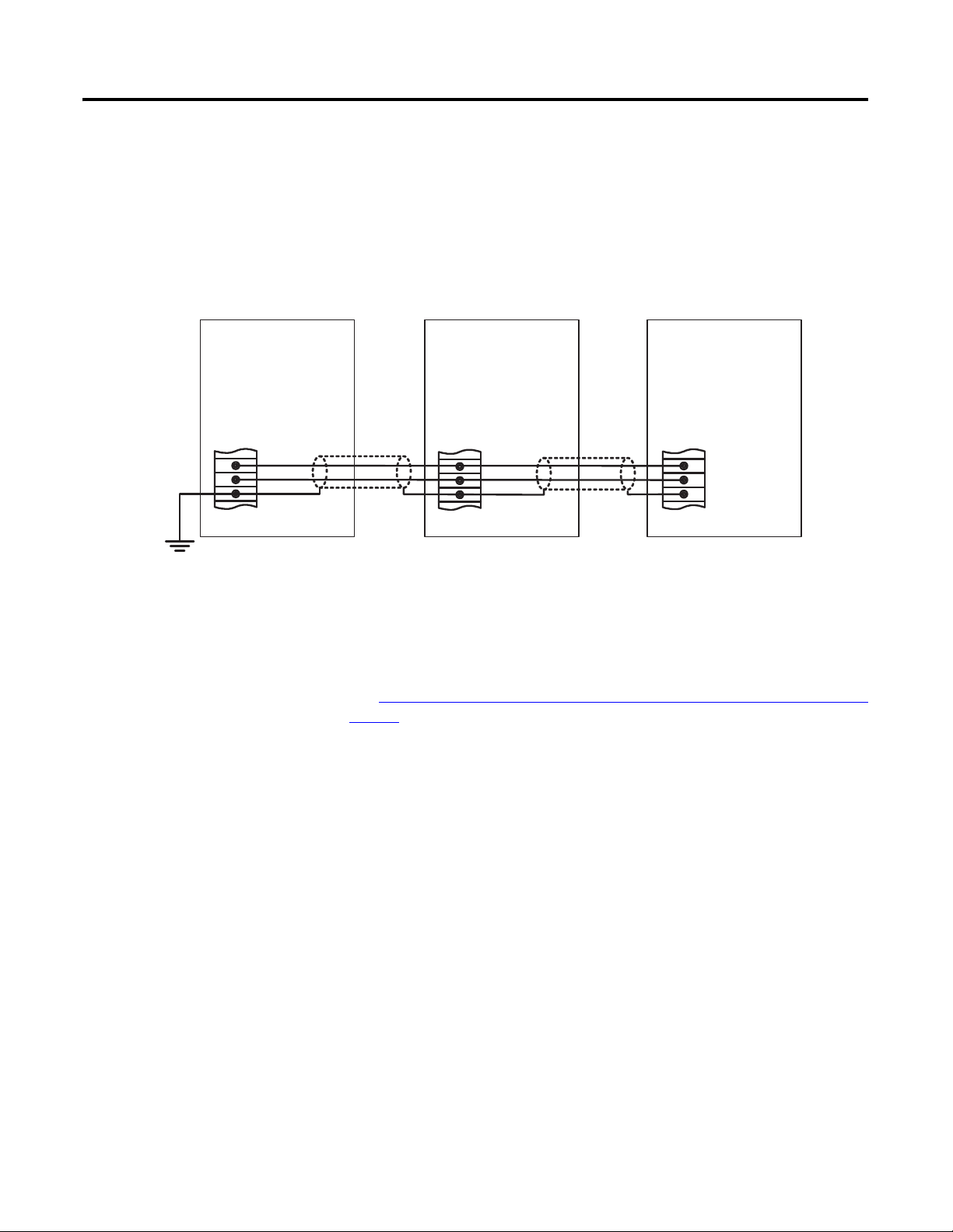
Real-power Load Sharing
The load sharing terminals connect to a 0…5V DC, internally powered circuit.
The load sharing terminals are on TB7 and are labeled LS(+) and LS(-). Terminal
SHLD4 is provided to land the cable shield. Twisted, shielded cabling is required
for the load sharing connections.
Figure 23 - Real-power Load Sharing
Ground shield at
only one point.
TB7
LS (+)
LS (-)
SHLD 4
CGCM 1 CGCM2 CGCM3
TB7
LS (+)
LS (-)
SHLD 4
LS (+)
LS (-)
SHLD4
TB 7
Cross-current Compensation
The Cross-current (reactive differential) Compensation Connection Diagram on
page 34 shows a typical connection diagram for three paralleled generators using
the 5 A sensing input range on the AC current input.
Make connections with 2.6 mm (10 AWG) copper wire for CT inputs.
The resistance of the cross-current CT wiring must be as low as possible. A loop
resistance less than 10% of the internal cross -current burden resistance of
(1)
1.0
CCCT loop resistance must be higher, adjust the CCCT gain or increase the
cross-current burden resistance. You can do those things by adding external
resistance to each CGCM unit in the loop.
enables cross-current operation with negligible voltage droop. If the
The cross-current compensation terminals are on TB3 and are labeled ID(-) and
ID(+). One and five ampere range terminals are provided.
(1) Series C devices have internal 1 resistor. Earlier devices can require an external resistor.
Rockwell Automation Publication 1407-UM001G-EN-P - April 2013 33
Page 34

Chapter 2 Installation
ID (+ ) 5A
ID (-)
ID (+ ) 1A
L 1 L2 L3
G
G2
A
C
B
L1 L2 L3
L1 L2 L3
G
G3
A
C
B
G
G1
A
C
B
TB 3
ID (+ ) 5 A
ID ( -)
ID (+ ) 1 A
TB 3
ID (+ ) 5 A
ID ( -)
ID (+ ) 1 A
TB 3
Ground
cross-current loop
at only one point
(optional).
Customer
Supplied CT
Shorting Switch
or Test Block
(typical)
Cross-
current CT
(typical)
L1 L2 L3
G
A
C
B
X
Z
Y
L1 L2 L3
G
A
C
B
X
Z
Y
ABC Generator ACB Generator
Cross-
current CT
(typical)
Figure 24 - Cross-current (reactive differential) Compensation Connection
Diagram
Figure 25 - Typical Cross-current CT Locations and Polarity
34 Rockwell Automation Publication 1407-UM001G-EN-P - April 2013
Page 35

Installation Chapter 2
To CGCM Unit
DB-9 Female
To CGCM Unit
DB-9 Female
Communication Connectors and Settings
There are three ports on the unit: the factory calibration port, the redundancy
port (COM1), and the ControlNet network port.
Factory Calibration Port
The factory calibration port is not intended for use by anyone other than
qualified factory representatives.
Redundancy Port (COM1)
The DB-9 female connector on the bottom side of the CGCM unit is used for
communication with another CGCM unit when operating in a redundant
system configuration. Use a null modem cable for this connection.
See
CGCM Unit Interconnection Cable table for connector pin numbers,
functions, names, and signal directions.
The cable pin-out is illustrated in the CGCM Unit Interconnection Cable
Diagram.
Table 2 - CGCM Unit Interconnection Cable
Pin Name Description Function
1 Not used
2 XMIT Transmit Sends serial data from CGCM unit
3 RCV Receive Receives serial data from CGCM unit
4 DTR Data terminal ready Receives a signal that the sending unit is operational
5 GND Ground Provides the ground signal
6 DSR Data set ready Sends a signal that the CGCM unit is operational
7, 8, 9 Not used
Figure 26 - CGCM Unit Interconnection Cable Diagram
Rockwell Automation Publication 1407-UM001G-EN-P - April 2013 35
Page 36

Chapter 2 Installation
ControlNet Network Port
Two ControlNet tap cables and channel labels are included with the
1407-CGCM unit.
You can use the mounting fasteners provided on the right-hand side of the unit
chassis to fasten the tap cables. Minimum bend radius for the ControlNet tap
cables is 38 mm (1.5 in.). Take care not to kink or pinch the ControlNet tap cable
or bend it more sharply than the minimum radius. Panduit HLM-15RO
hook-and-loop wraps are recommended for securing the tap cable to chassis
mounts.
Use the thumbwheel switches on the front of the CGCM unit to set the
ControlNet network node address (MAC ID).
For installation procedures, please refer to ControlNet Coax Media Planning and
Installation, publication CNET-IN002
.
36 Rockwell Automation Publication 1407-UM001G-EN-P - April 2013
Page 37

Chapter
DC
3
CGCM Unit Operation
This section provides a operational description of the CGCM unit’s functions.
The CGCM unit incorporates hardware inputs and outputs, software inputs and
outputs to a Logix family programmable controller, configuration settings, and its
internal control algorithms to provide the regulation, synchronizing, and
protection functions described in this section.
For information on configuring the CGCM unit, see Chapter
For further information on the software interface between the CGCM unit and
its host Logix programmable controller, see Chapter
Interface.
The Simplified Block Diagram
CGCM unit.
Figure 27 - Simplified Block Diagram
provides a functional block diagram for the
6, CGCM Unit Software
4, Configuration.
Rockwell Automation Publication 1407-UM001G-EN-P - April 2013 37
Page 38

Chapter 3 CGCM Unit Operation
Inputs and Outputs
The figure below shows the front panel layout of the CGCM unit. Input and
output connections are made through the terminal blocks TB1…TB7.
Figure 28 - Front Panel Layout
V Gen A
V Gen B
V Gen C
V Gen N
V Bus A
V Bus B
V Bus C
V Bus N
TB5
TB6
4
CNA
CNB
PMG A
PMG B
PMG C
SHLD 1
SHLD 1
TB1
ControlNet
BAT (+)
BAT (-)
FLT
RD RLY
CH GND
TB4
5
Address
SHLD 2
SHLD 2
EXC (+)
EXC (-)
Combination
Generator
Control Module
ID (+) 1A
ID (+) 5A
ID (-)
I3 (+) 1A
I3 (+) 5A
I3 (-)
I2 (+) 1A
I2 (+) 5A
I2 (-)
I1 (+) 1A
I1 (+) 5A
I1 (-)
TB3
TB2
Manufactured by
Basler Electric
R
HAZARDOUS VOLTAGE CAN CAUSE S HOCK, BURNS, OR DEATH.
1) DISCONNECT AND LOCK OUT ALL POWER SOURCES AND,
2) SHORT ALL CURRENT TRANSFORMER SECONDARIES BEFORE S ERVICING.
ADVERTISSMENT: CET EQUIPEMENT RENFERME PLUSIEURS CIRCUITS SOUS TENSION, VOIR LE SCHEMA
MORE THAN ONE LIVE CIRCUIT. SEE DIAGRAM.
DANGER
VREF (+)
VREF (-)
SHLD 3
SHLD 3
A-COM
EX-D (+)
EX-D (-)
LS (+)
LS (-)
SHLD 4
TB7
Factory
Test
Port
Analog Inputs
The CGCM unit provides a number of analog inputs for use in the regulation
and control of stand-alone and paralleled generator systems. Each of the inputs is
outlined below.
Generator Voltage Sensing Inputs
The CGCM unit senses generator voltage through voltage transformers (VTs)
installed across the generator output leads.
38 Rockwell Automation Publication 1407-UM001G-EN-P - April 2013
Page 39

CGCM Unit Operation Chapter 3
The CGCM unit uses voltages measured through the generator voltage sensing
inputs for generator voltage, VAR and/or power factor regulation, kW and kVAR
load sharing, synchronization, metering, and protection. The inputs accept
signals with up to 40% Total Harmonic Distortion (THD) and are connected for
single-phase and 3-phase applications. The generator voltage inputs are internally
scaled by the CGCM unit according to its transformer configuration settings.
Generator voltage sensing inputs are labeled V Gen A, V Gen B, V Gen C, and V
Gen N.
Bus Voltage Sensing Inputs
Voltages measured through the bus voltage sensing inputs are used for generator
to bus synchronizing. The CGCM unit senses bus voltage through VTs.
Depending upon the number of busses and the type of synchronizing required,
there is one or two sets of bus sensing transformers. If dual bus synchronizing is
required, the sensing transformer configuration is limited to single-phase. In a
single breaker system the inputs are connected in either single-phase or 3-phase
configurations. The inputs accept signals with up to 40% THD. The bus voltage
inputs are internally scaled by the CGCM unit according to its transformer
configuration settings.
Bus voltage sensing inputs are labeled V Bus A, V Bus B, V Bus C, and V Bus N.
Generator Line Current
The CGCM unit senses generator current through current transformers installed
on the generator output leads.
Current measured through the line current inputs is used for metering purposes,
regulating generator vars, regulating generator PF, real power load sharing, and
for protection purposes; and is required for operation in AVR Droop, PF, and
VAR operating modes. Line current inputs are galvanically isolated via CTs
internal to the CGCM unit. The CGCM unit accepts either 1 A or 5 A current
inputs wired to the corresponding input. Line current inputs are labeled I1(+)1
A, I1(+)5 A, I1(-), and so forth.
Cross-current
The CGCM unit senses reactive differential current through properly connected
current transformers typically installed on the B-phase output leads of each
paralleled generator.
See Typical Cross-current CT Locations and Polarity
information.
on page 34 for more
Line current inputs are galvanically isolated via CTs internal to the CGCM unit.
The CGCM unit accepts either 1 A or 5 A current inputs. The cross-current
input terminals are labeled ID(+)5A, ID(+)1A, and ID(-).
Rockwell Automation Publication 1407-UM001G-EN-P - April 2013 39
Page 40

Chapter 3 CGCM Unit Operation
IMPORTANT
Auxiliary Input
This input is an analog voltage (-10…10V DC), and provides a means to remotely
adjust the regulation point of the generator. Resistive isolation is provided
through the use of differential amplifiers.
The auxiliary input terminals are labeled VREF(+) and VREF(-).
Power Inputs
The unit has two types of power inputs: control power inputs and excitation
power inputs.
Control Power Input
The CGCM unit operates from a nominal 24V DC supply connected to the
control power inputs. The control power input is diode-protected to protect
against equipment damage due to improper polarity of the applied power.
The control power inputs are labeled BAT(+) and BAT(-).
Excitation Power Input
The CGCM unit accepts either 3-phase or single phase excitation power.
Excitation power can be obtained from the generator or the utility via shunt
excitation (SE) or from the generator prime mover via a Permanent Magnet
Generator (PMG).
See Chapter
The excitation power input terminals are labeled PMG A, PMG B, and PMG C.
2 for details on connections for SE or PMG operation.
Discrete Inputs - Remote Excitation Enable
The remote excitation enable input is a 24V DC input. When 24V DC is applied
to the input, CGCM unit excitation is permitted.
For generator excitation to occur, excitation must be enabled in software,
an active ControlNet connection must be present, and a 24V DC signal
must be applied to the remote excitation enable input.
The remote excitation enable input terminals are labeled EX-D(+) and EX-D(-).
40 Rockwell Automation Publication 1407-UM001G-EN-P - April 2013
Page 41

CGCM Unit Operation Chapter 3
Analog Outputs
The unit has two types of analog outputs: excitation output and real power load
sharing.
Excitation Output
The CGCM unit Pulse Width Modulated (PWM) power stage provides DC
generator exciter field current. The excitation power stage is designed to
accommodate up to 125V DC (nominal) field voltages.
Refer to Excitation Control Modes
Care must be taken that the field resistance does not allow more than 15 A DC to
flow continuously at rated field voltage.
Minimum resistance for common voltages is given in Appendix
The CGCM unit excitation output is equipped with a high-speed circuit for
detecting a shorted output. The excitation output is clamped at a very low level
when a low impedance connection is detected. The CGCM unit indicates that
the clamp is active by setting Spare2 bit in the Scheduled Read Data Table. The
Spare2 bit indication is reset by either setting the tag SoftwareExcEN = 0 or by
cycling the control power to the CGCM unit.
Note that a loss of ControlNet network communication with the host Logix
controller causes the CGCM unit to automatically shutdown generator
excitation.
The excitation output terminals are labeled EXC(+) and EXC(-).
on page 44 for a description of operation.
D.
Real-power Load Sharing
Real-power load sharing terminals are provided to allow two or more CGCM
units or other compatible generator control devices (such as the Line
Synchronization Module, catalog number 1402-LSM) to load the generators
under their control such that the same per unit output is developed by each
generator.
Load sharing terminals are labeled LS(+) and LS(-).
Rockwell Automation Publication 1407-UM001G-EN-P - April 2013 41
Page 42

Chapter 3 CGCM Unit Operation
Discrete Outputs
The CGCM unit provides two discrete open collector outputs, the fault output
and the redundancy relay output. These are sinking type outputs internally
connected to the control power BAT(-) supply. They are intended to drive a
user-supplied relay connected between the control power BAT(+) supply and the
applicable discrete output terminal.
Fault Output
The fault output can be used to annunciate a fault via a user-supplied relay. The
user chooses, from a predetermined list, the conditions for this output. The fault
output is labeled FLT.
The fault enable output tags in the Output table determine which faults activate
the fault relay output.
Redundancy Relay Output
Communication
The redundancy relay output is used to transfer excitation of the generator from
the primary CGCM unit to the redundant CGCM unit in dual unit systems.
The redundancy relay output is labeled RD RLY.
The CGCM unit provides three communication ports along with software
inputs and outputs.
Com 0 Factory Test Port
Not for customer use. This port is used to calibrate the CGCM unit during
factory testing.
Com 1 Redundancy Port
The redundancy port lets one CGCM unit communicate with its partner
CGCM unit in a redundant system, letting the partner unit auto-track the
primary unit's control modes.
ControlNet Network Port
The version 1.5 ControlNet network port is used to interface with a Logix family
programmable logic controller. Through this port, RSLogix 5000 software
facilitates setting CGCM unit configuration parameters. Control, metering, and
protection settings are communicated to the CGCM unit by using this port. The
CGCM unit firmware is flash programmable through this port.
42 Rockwell Automation Publication 1407-UM001G-EN-P - April 2013
Page 43

CGCM Unit Operation Chapter 3
Software Inputs and Outputs
Your Logix family host programmable controller must include the hardware and
communication interfaces with the generator, prime mover, power system, and
balance of plant that are not specifically included in the CGCM unit module.
The software interface between the CGCM unit and its host controller is made
via the ControlNet software interface. The specific interface consists of several
assembly instances, or data tables.
• The Input (Scheduled Read) table provides time-critical status and fault
parameters, and control commands, from the CGCM unit to the host
Logix controller.
• The Output (Scheduled Write) table provides time-critical enable
commands, selection commands, and setpoints from the host controller to
the CGCM unit.
• The Unscheduled Read table provides non time critical metering data
from the CGCM unit to the host controller.
• The Unscheduled Write table provides a means to adjust selected gains and
(in firmware revision 3.x or later) energy counter presets while excitation is
enabled.
• The Configuration table contains the basic CGCM unit configuration
parameters and is automatically transferred from the host controller to the
CGCM unit on powerup and at other times when excitation is not
enabled.
Operational Functions
Refer to Chapter
information on the CGCM unit software interface.
The following sections describe the operational functions of the CGCM unit.
The functions include the following:
• Excitation Control Modes
• Limiting Functions
• Protection Functions
• Synchronizing
• Real-power Load Sharing
• Metering
• Redundancy
• Watc hd og T im er
6, CGCM Unit Software Interface, for more detailed
Rockwell Automation Publication 1407-UM001G-EN-P - April 2013 43
Page 44

Chapter 3 CGCM Unit Operation
Excitation Control Modes
The CGCM unit controls the DC excitation current of the generator exciter
based on a number of factors, including the following:
• The selected control mode
• The configuration of the CGCM unit including gains
• Measured generator voltage and current
• The applicable setpoint or setpoints
• The value of the Auxiliary Input
• Vari ou s l im itin g f un ct ions
The CGCM unit offers several modes of regulation that are selected and
activated by using the software interface to the host Logix programmable
controller. An active ControlNet network connection must exist with the host
Logix controller for any regulation mode to be active.
The CGCM unit automatically shuts down excitation if one of these faults
occurs:
• Overexcitation voltage
• Reverse VAR
• Logix controller fault
Gains
The CGCM unit regulates excitation current by using a proportional, integral,
and derivative (PID) control algorithm. The regulatory response of the CGCM
unit is determined by your gain settings. The gains for each mode include the
following:
• Proportional Gain Kp – determines the basic response to changes in
generator voltage
• Integral gain Ki – speeds the return to steady state voltage after a
disturbance
• Derivative gain Kd – speeds the initial regulator response to a disturbance
• Overall gain Kg – adjusts the coarse loop gain of the regulator
• Auxiliary Gain – adjusts the effect of the auxiliary input on the regulator
output
Please refer to Chapter
information.
4, CGCM Unit Configuration, for more detailed
44 Rockwell Automation Publication 1407-UM001G-EN-P - April 2013
Page 45

CGCM Unit Operation Chapter 3
Field Current Regulation Mode (FCR)
FCR mode provides manual control of the excitation current. In FCR mode, the
CGCM unit measures and controls its field excitation current output to maintain
the commanded field current setpoint. The FCR feedback loop includes
adjustable proportional, integral, and derivative gains. In FCR mode, automatic
voltage control, reactive power control, power factor control, over-excitation
limiting, and under-excitation limiting are disabled. To activate FCR mode:
• the gains must be set.
• FCR mode must be selected (tag AVR_FCR_Select = 1).
• the desired setpoint must be written to the FCRSetpt tag.
• excitation enabled (tag SoftwareExcEn = 1).
• remote Excitation Enable On (discrete input).
Automatic Voltage Regulation Mode (AVR)
AVR mode provides automatic control of the excitation current. In AVR mode,
the CGCM unit controls field excitation current output to maintain the
commanded generator voltage setpoint. The AVR feedback loop includes
adjustable proportional, integral, and derivative gains. To activate AVR mode:
• the metering VTs must be properly connected and configured.
• the AVR gains must be set.
• AVR mode must be selected (tag AVR_FCR_Select = 0).
• the desired setpoint must be written to the AVR S e t p t tag.
• excitation enabled (tag SoftwareExcEn = 1).
• remote Excitation Enable On (discrete input).
• for constant voltage control, droop must be disabled
(tag V_DroopEn = 0).
Droop (reactive current compensation)
Droop (reactive current compensation) is a method of controlling reactive
current when a generator is connected in parallel with another energy source.
Droop adjusts the generator voltage in proportion to the measured generator
reactive power. The CGCM unit calculates reactive power by using the 3-phase
generator voltage and current sensing inputs. The droop adjustment represents
the percent reduction from the generator voltage setpoint when the generator
produces reactive power corresponding to rated generator kVA.
Rockwell Automation Publication 1407-UM001G-EN-P - April 2013 45
Page 46

Chapter 3 CGCM Unit Operation
To ac ti va te dr oop :
• the metering CTs and generator VTs must be properly connected and
configured.
• the desired droop setpoint must be written to the V_DroopSetpt tag.
• excitation enabled (tag SoftwareExcEn = 1).
• remote Excitation Enable On (discrete input).
• the CGCM unit must be in AVR mode (tag AVR_FCR_Select = 0).
• droop must be enabled (V_DroopEn tag = 1).
• droop must be selected (Droop_CCC_Select tag = 0).
• automatic reactive power control must be disabled (tag PF_VAR_En = 0).
Cross-current Compensation
Cross-current compensation (reactive differential compensation) is a method of
connecting multiple generators in parallel to share reactive load. Cross-current
compensation requires the connection of an additional CT into the cross-current
compensation input. The CGCM unit operates in a stand-alone application
without the cross-current inputs connected.
The cross-current compensation method of reactive load sharing is possible with
other controllers of similar type. Cross-current compensation monitors the ID
current, V GEN A, and V GEN C inputs to adjust the excitation level. A gain
adjustment is provided to allow tuning of the cross current control. Cross-current
compensation is configured and controlled by using the software interface to the
Logix controller.
To activate cross-current compensation:
• the generators must be connected in parallel.
• the cross-current CT and generator VTs must be properly connected.
• the desired cross-current gain must be written to the CrossCurrentGain
tag.
• excitation enabled (tag SoftwareExcEn = 1).
• remote Excitation Enable On (discrete input).
• the CGCM unit must be in AVR mode
(tag AVR_FCR Select =0).
• droop must be enabled (V_DroopEn tag = 1).
• cross-current compensation must be selected (Droop_CCC_Select tag
= 1) (and KVAR _LS_En tag = 1 for firmware rev. 2.x).
When cross-current compensation is disabled or control power is removed from
the unit, the cross-current input terminals ID(+) and ID(-) are internally
connected together through a very small impedance.
(1)
(1) For series B devices, the input terminals are not connected together when control power is removed.
46 Rockwell Automation Publication 1407-UM001G-EN-P - April 2013
Page 47

CGCM Unit Operation Chapter 3
Auxiliary Input Regulation Adjustment
The auxiliary input provides a means to remotely adjust the regulation point of
the generator. This analog voltage (-10…10V DC) input signal changes the
setpoint of the selected operating mode by one percent of the applicable rated
value for each volt applied (positive or negative), multiplied by the auxiliary gain
setting for AVR/FCR or VAR/PF.
Refer to Chapter 4
for more information.
Auxiliary input gain settings range from -99…99. If the gains are set to zero, the
auxiliary input is inactive.
A typical use for this input is with a Power System Stabilizer where adjusting the
regulation point of the generator can increase system stability during power
system kW swings.
Line-drop Compensation
Line-drop compensation adjusts generator voltage proportional to generator
load. Line-drop compensation can be used to maintain voltage at a load that is at
a distance from the generator. Generator output reactive current is used to
increase the generator voltage with increasing load, based on the user
configurable line-drop compensation factor. Line-drop compensation is
adjustable from 0…10% of the voltage setpoint in 0.1% steps, which represents
the percent voltage change at rated generator current. Line-drop compensation
cannot be used with droop or cross-current compensation.
Power Factor Regulation Mode (PF)
In PF mode, the CGCM unit controls field excitation current output to maintain
the commanded power factor setpoint. The CGCM unit uses the measured
generator voltages and currents to calculate power factor. The PF feedback loop
includes adjustable proportional and integral gains. To activate PF mode:
• the metering CTs and VTs must be properly connected and configured.
• the PF mode gains must be set.
• the desired power factor setpoint must be written to the PFSetpt tag.
• excitation enabled (tag SoftwareExcEn = 1).
• remote Excitation Enable On (discrete input).
• the CGCM unit must be in AVR mode (tag AVR_FCR_Select = 0).
• droop must be enabled (V_DroopEn tag = 1).
• droop must be selected (Droop_CCC_Select tag = 0).
• automatic reactive power control must be enabled (tag PF_VAR_En = 1).
• power factor control must be selected (tag PF_VAR_Select = 0).
Rockwell Automation Publication 1407-UM001G-EN-P - April 2013 47
Page 48

Chapter 3 CGCM Unit Operation
Reactive Power Regulation Mode (VAR)
In VAR mode, the CGCM unit controls field excitation current output to
maintain the commanded reactive power setpoint. The CGCM unit uses the
measured generator voltages and currents to calculate reactive power. The VAR
feedback loop includes adjustable proportional and integral gains. To activate
VAR mo de :
• the metering CTs and VTs must be properly connected and configured.
• the VAR mode gains must be set.
• the desired reactive power setpoint must be written to the VARS et p t tag.
• excitation enabled (tag SoftwareExcEn = 1).
• remote Excitation Enable On (discrete input).
• the CGCM unit must be in AVR mode (tag AVR_FCR_Select = 0).
• droop must be enabled (V_DroopEn tag = 1).
• droop must be selected (Droop_CCC_Select tag = 0).
• automatic reactive power control must be enabled (tag PF_VAR_En = 1).
• VAR control must be selected (tag PF_VAR_Select = 1).
Soft Start Mode
CGCM unit Soft Start mode provides for an orderly build-up of generator
voltage from residual to the voltage setpoint in the desired time with minimal
overshoot. When the system is in Soft Start mode, the CGCM unit adjusts the
voltage reference based on the Soft Start Initial Voltage and Soft Start Time.
The Soft Start Voltage Reference
showing soft start initial voltage at 30%, soft start time at 8 seconds.
Figure 29 - Soft Start Voltage Reference
illustration is a graph for the voltage reference
48 Rockwell Automation Publication 1407-UM001G-EN-P - April 2013
Page 49

CGCM Unit Operation Chapter 3
If the generator is not up to speed when the soft start begins, the voltage increases
but only to the level determined by Volts/Hz limiting . When the unit is operating
in FCR mode, soft start operates as it does in the AVR mode, with the field
current, rather than the generator voltage, being the controlled parameter.
To activate soft start mode:
• the Soft Start Initial Voltage (tag SoftStart_InitLevel) and Soft Start
Time (tag SoftStartTime) parameters must be set.
• excitation enabled (tag SoftwareExcEn = 1).
• remote Excitation Enable On (discrete input).
• FCR mode not active (tag AVR_FCR_Select = 0).
• engine idle bit is set (tag EngineIdle = 1).
Internal Tracking
The CGCM unit provides a tracking function between the non-active modes of
operation and the active mode of operation, to minimize the potential for
instability that can occur when switching from one mode to another. There are
two settings you can configure. The internal tracking rate defines the time
constant of a first-order filter through which the CGCM unit matches the
non-active modes with the active mode and is scaled in seconds. The time for the
tracking function to settle out after a step change in the operating setpoint is
approximately four times the internal tracking rate setting.
The internal tracking delay setting adjusts the delay of the tracking function to
prevent a non-active mode from being adjusted into an undesirable condition.
For example, with AVR mode active, if the generator sensing VT fails open, the
excitation output goes to a full-on state. Applying a tracking delay reduces the
likelihood of this undesirable operating point being transferred to a new
operating mode.
Traverse Rates
You can control the speed at which the CGCM unit switches from one
regulation mode to another by configuring traverse rates for each regulation
mode. These settings define the rate at which the system changes to the new
setpoint when the mode changes. At the instant the mode is changed, the
regulator begins changing its operating point from the internal tracking setpoint
to the new mode's setpoint at a rate determined by the new mode's traverse rate.
Please refer to Chapter
settings.
Increasing a traverse rate causes the regulator output to change more slowly. A
value of 200 seconds is a special case that causes the CGCM unit to hold the
existing regulator output until the new setpoint is adjusted to become equal to or
pass through the previous mode's setpoint.
4 for information on scaling and units of the traverse rate
Rockwell Automation Publication 1407-UM001G-EN-P - April 2013 49
Page 50

Chapter 3 CGCM Unit Operation
1.0
0.8
0.6
0.4
0.2
0.0
-0.2
-0.4
-0.6
-0.8
-1.0
0.0 0.2 0.4 0.6 0.8 1.0 1.2 1.4
LaggingLeading
Reactive Power, per Unit
Rating PF
Lagging
Armature Winding
Heating Limitation
Prime Mover
Power Limitation
95% PF
Leading
Armature Core
End Iron Heating
Limitation
Field Winding
Heating Limitation
Real Power, per Unit
The tag SetptTraverseActive = 1 when the CGCM unit is traversing between
the internal tracking setpoint and the new operating mode's setpoint. The tag = 0
when the operating point has completed traversing to the new mode's setpoint.
This tag is used by the host Logix controller to determine when the new mode
has taken control.
Limiting Functions
This section discusses the different types of limiting functions the CGCM unit
provides.
• Volts/Hertz Limit
• Over-excitation Limit
• Under-excitation Limit
Generator Capability Curve
The generator capability curve graphically depicts the combinations of real and
reactive power a generator is able to produce (or absorb, in the case of reactive
power) without damage caused by overheating. The CGCM unit provides a
number of limiting functions designed to maintain operation within safe areas of
the generator capability curve.
A typical generator capability curve is shown in the following illustration.
Figure 30 - Typical Generator Capability Curve
50 Rockwell Automation Publication 1407-UM001G-EN-P - April 2013
Page 51

CGCM Unit Operation Chapter 3
100
90
80
70
60
50
40
30
20
10
0
0 102030405060708090
Underfrequency Slope
Frequency (Hz)
Voltage (%)
Volts/Hertz Limit
Volts/Hertz limiting acts to reduce the generator output voltage by an amount
proportional to generator frequency. This is done to protect the generator from
overheating and reduce the impact on the prime mover when adding a large load.
When the generator frequency drops, the voltage setpoint is automatically
adjusted by the CGCM unit so that generator voltage follows the
under-frequency slope.
The CGCM unit provides two configurable knee frequencies and two
configurable slopes that allow the user to define the Volts/Hz characteristic. The
slopes are expressed in PU Volts / PU Hertz. For a nominal 60 Hz, 120V system,
a slope of one corresponds to 2V per Hz. The generator output voltage is
maintained at the configured level for any frequency at or above the configured
knee frequency up to 90 Hz. Excitation is inhibited when the frequency is at or
below the 10 Hz cutoff frequency.
The Under-frequency Slope and Knee Voltages
graph shows a typical Volts/Hz
characteristic as displayed in the RSLogix 5000 software CGCM unit
configuration screen.
Volts/Hertz limiting is automatically enabled in AVR mode and limits the
voltage increase in Soft Start mode.
Figure 31 - Under-frequency Slope and Knee Voltages
Rockwell Automation Publication 1407-UM001G-EN-P - April 2013 51
Page 52

Chapter 3 CGCM Unit Operation
FIELD CURRENT
TIME IN SECONDS
High
Current
Time
0…10 seconds
CONTINUOUS
Medium
Current
Time
0…120 seconds
Low
Current
Level
0.0…15 A dc
Medium
Current
Level
0.0… 20 A dc
High
Current
Level
0.0…30 A dc
Over-excitation Limit
Over-excitation limiting (OEL) operates in all modes except FCR. The CGCM
unit senses and limits the field current to prevent field overheating. When the
limit is reached, the limiter function overrides AVR, VAR, or Power Factor
modes to limit field current to the preset level. OEL operates in the area above
the Field Winding Heating Limitation curve in the generator capability curve.
The generator operates in one of two different states, offline or online. The
generator is offline when it is operating in a constant-voltage mode. The CGCM
unit is considered online if any of these modes are enabled:
• Droop (reactive power) compensation
• Cross current compensation
• Line drop compensation
Two OEL current levels, high and low, are defined for offline operation as shown
in the graph below. The generator can operate continuously at or below the low
OEL current level and for a time at the high OEL current level that you
configure.
Figure 32 - Offline Over-excitation Limiting
High
Current
Current
0…10 seconds
FIELD CURRENT
High
Time
CONTINUOUS
Current
Level
0…15 A dc
Low
Level
0…30 A dc
TIME IN SECONDS
Three OEL current levels, high, medium, and low are defined for online
operation as shown in the graph below. The high and medium current levels can
be maintained only for time periods you define. The generator can operate
continuously at or below the low OEL current level.
Figure 33 - Online Over-excitation Limiting
52 Rockwell Automation Publication 1407-UM001G-EN-P - April 2013
Page 53

CGCM Unit Operation Chapter 3
TIP
The CGCM unit also uses two counters, the reset counter and the time limit
counter. The counters are used to prevent excessive heating of the exciter field
that can be a result of repeated over-excitation. The time limit counter monitors
the duration of an over-excitation condition. The reset counter counts backward
from either the high OEL time setting or the sum of the high and medium OEL
times, depending on the value of the time limit counter.
If, during an OEL cycle, excitation current returns below the low current value,
the reset counter begins counting backwards from its present value. If it reaches
zero, the time limit counter is reset to zero and a new OEL cycle can then occur.
If the reset counter does not reach zero before the excitation current rises above
the low current value, the time limit counter begins counting where it stopped
when the excitation current last fell below the low current value. If the time limit
counter is greater than the programmed high OEL time, the excitation current is
limited to the medium current value. This prevents repeated cycling of the exciter
field at its highest possible current value.
When the excitation current exceeds the OEL limit, the OEL alarm tag
OEL_Active = 1. In FCR mode, OEL limiting is not active although the tag is
set. This tag is in the Scheduled Read table. The OEL function meets
ANSI/IEEE C50.13.
Under-excitation Limit
Under-excitation limiting (UEL) operates in all modes except FCR mode. UEL
senses the leading var input of the generator and limits any further decrease in
excitation to prevent loss of synchronization and excessive end-iron heating
during parallel operation. UEL operates in the area below the Armature Core
End Iron Heating Limitation curve in the generator capability curve.
The UEL function is not designed to prevent the loss of excitation
function from operating.
A customizable UEL limiting curve is defined by a piecewise linear curve
specified by five points you select as shown in the Typical UEL Limiting Curve
diagram.
When the excitation current is less than the UEL curve, the UEL alarm tag
UEL_Active = 1. In FCR mode, UEL limiting is not active although the tag is
set. This tag is in the Scheduled Read table.
Rockwell Automation Publication 1407-UM001G-EN-P - April 2013 53
Page 54

Chapter 3 CGCM Unit Operation
Real Power Generate (W) x 1000
0.0 7.5k 15.0k 22.5k 30.0k 37.5k 45.0k
0.0
2.5k
5.0k
7.5k
10.0k
12.5k
15.0k
Reactive Power Absorb (var) x 1000
Figure 34 - Typical UEL Limiting Curve
Protection Functions
The CGCM unit detects the fault conditions listed and described below. Faults
detected by the CGCM unit are communicated to the host Logix programmable
controller. Fault flags are communicated in the Scheduled Read table. A fault flag
is latched until the host controller resets it. The host Logix controller can reset all
CGCM unit faults by setting the tag FltReset = 1 once the fault condition is
cleared.
The CGCM unit automatically shuts down excitation if one of these faults
occurs:
• Overexcitation voltage
• Reverse VAR
• Logix controller fault
Fault conditions can also be configured to activate the CGCM unit fault relay
output. Once configured, the CGCM unit fault relay operates independently of
the host Logix controller program (including Controller Run/Program mode).
Refer to Chapter
4 for information on configuring the fault relay operation.
CGCM Protection Capabilities
The protective functions in the CGCM unit are time-proven and designed to
provide a high degree of reliability, repeatability, longevity, and accuracy. The
CGCM unit is designed to meet or exceed applicable CE standards, but was not
tested to all standards that many North American utilities use to define utility
grade protection. However, the CGCM unit does possess many of the features
that define utility grade protection.
54 Rockwell Automation Publication 1407-UM001G-EN-P - April 2013
Page 55

CGCM Unit Operation Chapter 3
The CGCM unit can be used as primary protection in applications not requiring
utility grade protection or in utility applications where the authority having
jurisdiction has approved the CGCM unit for use as primary protection. In
applications requiring utility grade protection, where the local authority has not
evaluated or approved the CGCM unit, the CGCM unit can be used for
secondary protection in conjunction with a primary protection system.
Loss of Excitation Current (40)
The CGCM unit activates this fault when excitation current metered by the
CGCM unit falls below the user specified loss of excitation current setpoint for
more than the user defined delay time. In a redundant CGCM unit system,
excitation is disabled and a transfer to the secondary controller occurs. If this fault
occurs, tag LossExcFlt = 1 in the Scheduled Read table. This fault is inhibited
during voltage build and when soft start is active.
Over-excitation Voltage (59F) (field over-voltage)
When the field voltage rises above the level you specified for more than a set
amount of time, a field over-voltage annunciation occurs. Once the field voltage
drops below the threshold, the field over-voltage timer is reset. If this fault occurs,
the CGCM unit shuts down excitation and sets tag OvrExcFlt = 1 in the
Scheduled Read table.
Generator Over-voltage (59)
When the generator voltage rises above the level you specified for more than a set
amount of time, a generator over-voltage annunciation occurs. Once the
generator voltage drops below the threshold, the generator over-voltage timer is
reset. If this fault occurs, tag
Ovr_V_Flt = 1 in the Scheduled Read table.
Generator Under-voltage (27)
When the generator voltage falls below the level you specified for more than a set
amount of time, a generator under-voltage annunciation occurs. Once the
generator voltage rises above the threshold, the generator under-voltage timer is
reset. This function is disabled during soft start timing or when the EngineIdle
tag is set. If this fault occurs, tag Undr_V_Flt = 1 in the Scheduled Read table.
Rockwell Automation Publication 1407-UM001G-EN-P - April 2013 55
Page 56

Chapter 3 CGCM Unit Operation
Loss of Sensing (60FL)
For three-wire and four-wire sensing, Loss of Sensing detection is based on the
logical combination of several conditions. They include these conditions:
1. The average positive sequence voltage is greater than 8.8% of the AVR
setpoint.
2. The negative sequence voltage is greater than 25% of the positive sequence
voltage.
3. The negative sequence current is less than 17.7% of the positive sequence
current.
4. The positive sequence current is less than 1% of rated current for
0.1 seconds.
5. The generator positive sequence voltage is less than 8.8% of the AVR
setpoint.
6. The positive sequence current is less than 200% of the rated current for
0.1 seconds.
The three phase loss of sensing is expressed by this logical formula:
Loss of Sensing = (1 and 2 and (3 or 4)) or (5 and 6)
For single-phase sensing, Loss of Sensing is detected when the following
conditions exist in the proper logical combination.
1. The average generator terminal line-to-line voltage is less than 70% of the
AVR s etpoint.
2. The positive sequence current is less than 200% of the rated current.
3. The negative sequence current is less than or equal to 17.7% of the positive
sequence current.
4. The positive sequence current is less than 1% of rated current for
0.1 seconds.
The single phase loss of sensing is expressed by this logical formula:
Loss of Sensing = ((1 and 2) and (3 or 4)
The time delay for this function is fixed at 0.1 seconds during normal operation
and increased to 1.0 seconds during soft start operation. Loss of Sensing is
disabled when the excitation current is less than the Loss of Excitation setpoint. If
this fault occurs, tag LossSensingFlt = 1 in the Scheduled Read table.
56 Rockwell Automation Publication 1407-UM001G-EN-P - April 2013
Page 57

CGCM Unit Operation Chapter 3
1.0
0.8
0.6
0.4
0.2
0.0
-0.2
-0.4
-0.6
-0.8
-1.0
0.0 0.2 0.4 0.6 0.8 1.0 1.2 1.4
LaggingLeading
Reactive Power, per Unit
Generator
Characteristic
Curve
Trip Region
Reverse VAR
Trip Setting
Real Power, per Unit
8˚
Loss of Excitation Power (PMG) (27)
If voltage to the PMG excitation power inputs falls below 10V AC for
approximately 400 ms or more, a Loss of Excitation power fault occurs. When
single phase PMG is selected, the CGCM unit senses phases A and C for this
function. This function is disabled when Shunt excitation is selected, the
EngineIdle tag is set, or the host Logix controller is in Program mode. If this fault
occurs, tag LossPMGFlt = 1 in the Scheduled Read table.
Reverse VAR (40Q)
When the Reverse VAR level exceeds the characteristic curve for an amount of
time you set, a Reverse VAR fault occurs. The characteristic curve is a line that
begins at the pickup setting you defined at zero real power and extends toward
positive reactive power at an angle of 8°. Once the VARs increase above the
threshold, the Reverse VAR fault timer is reset. If this fault occurs, the CGCM
unit shuts down excitation and sets tag RevVARFlt = 1 in the Scheduled Read
table.
The Reverse VAR Characteristic
Figure 35 - Reverse VAR Characteristic
graph shows more details.
Rockwell Automation Publication 1407-UM001G-EN-P - April 2013 57
Page 58

Chapter 3 CGCM Unit Operation
Over-frequency (81O)
When generator frequency exceeds the over-frequency setpoint for a specified
amount of time, a definite time over-frequency fault occurs. Once the frequency
drops below the threshold, the over-frequency fault timer is reset. If this fault
occurs, tag OvrFreqFlt = 1 in the Scheduled Read table.
Under-frequency (81U)
When generator frequency drops below the under-frequency setpoint for a
specified amount of time, a definite time under-frequency fault occurs. This
function is disabled during soft start timing, when no voltage is present on the
generator voltage sensing inputs, or when the EngineIdle tag is set. Once the
frequency rises above the threshold, the under-frequency fault timer is reset. If
this fault occurs, tag Und rFr eq Fl t = 1 in the Scheduled Read table.
Reverse Power Protection (32R)
When generator reverse power exceeds the reverse power setting for a specified
amount of time, a reverse power fault occurs. Once the reverse power drops below
95% of the threshold, the reverse power fault timer is reset. If this fault occurs, tag
RevPwrFlt = 1 in the Scheduled Read table.
Rotating Diode Failure
The Rotating Diode Monitor is capable of detecting one or more open or shorted
diodes in the generator’s rotor. If a failed diode is detected, a fault occurs.
The CGCM unit monitors specific harmonic components present in the field
current. The frequency of the harmonics is proportional to the system frequency
and the ratio between the main and exciter field poles.
For example, during normal operation at 60 Hz, a 3-phase exciter bridge produces
a ripple current frequency of 1080 Hz.
1080 Hz = 6 * 60Hz * (12 exciter poles / 4 main poles)
A shorted diode produces increased ripple current at 1/6 of the normal ripple
frequency or 180 Hz. Similarly, an open diode shows increased current at 1/3 of
the normal ripple frequency or 360 Hz. The CGCM unit senses harmonics in
the 1/6 and 1/3 harmonic levels to provide protection for these conditions.
When the ripple current at one of these frequencies exceeds the applicable user
specified threshold, a timer is started. Once the time delay is exceeded, a rotating
diode fault occurs. If the ripple current falls below the threshold (configured as
percent of measured excitation current) before the timer expires, the timer is
reset. If this fault occurs, tag RotDiodeFlt = 1 in the Scheduled Read table.
58 Rockwell Automation Publication 1407-UM001G-EN-P - April 2013
Page 59

CGCM Unit Operation Chapter 3
The Rotating Diode fault is inhibited if the field current is less than
1.5 A DC or if the generator frequency is outside the range of 45…70 Hz.
Phase Rotation Fault (47)
The CGCM unit calculates the negative sequence voltage of the 3-phase
generator voltage sensing input. When the generator phase rotation is opposite to
the wiring rotation you configured, the level of the generator negative sequence
voltage increases to approximately 100%. The pickup value for this function is
fixed at 66%. When the pickup value is exceeded, timing is started. After a one
second delay a phase rotation fault is indicated. A phase rotation fault is also
indicated when a phase loss condition occurs. If this fault occurs, tag
PhRotFlt = 1 in the Scheduled Read table.
Generator Over-current (51/51V)
A generator over-current fault occurs when generator current exceeds the
generator over-current function’s setpoint. You configure over-current protection
by selecting a time characteristic curve, an over-current setpoint, a time dial
setting and a voltage restraint setpoint. The over-current function meets
ANSI/IEEE C37.112.
See Appendix
If this fault occurs, tag Ovr_I_Flt = 1 in the Scheduled Read table.
A for a list of available curves and more detail.
Synchronizing
The CGCM unit monitors the generator and bus voltage sensing inputs to
provide synchronization between the generator and either of two buses. The
CGCM unit provides voltage, phase and frequency error parameters, and a
breaker close permissive signal, to its host Logix controller. This lets the
controller control the prime mover, achieve phase synchronization, and voltage
matching.
The CGCM unit can also provide synchronization between two busses by
measuring appropriate synchronization parameters. For synchronizing between
two busses, substitute the term second bus for generator in the discussions that
follow.
When synchronizing a system between systems with differing metering
configurations, the synchronization configuration must account for any phase
shift or voltage differences between the two systems. For example, when
synchronizing a three-wire (delta) generator to four-wire (wye) bus system, the
synchronization configuration must take into account the 30° phase shift
between line-to-line and line-to-neutral voltage.
Rockwell Automation Publication 1407-UM001G-EN-P - April 2013 59
Page 60

Chapter 3 CGCM Unit Operation
Synchronizing Connection Schemes
The CGCM unit provides information that its host Logix controller uses to
synchronize the generator output voltage, frequency, and phase to a reference
power system, or bus. 3-phase, dual bus, and single-phase connection schemes are
described below.
• 3-phase
In this scheme, the 3-phase output of the generator and all three phases of
the reference system are connected to the CGCM unit. This lets the
CGCM unit match voltage, frequency, phase, and phase rotation of the
generator to the reference system. The 3-phase scheme provides the
CGCM unit with the most power system data, allowing it to perform the
most thorough synchronization.
To enable a 3-phase connection, the user selects the Generator and Bus VT
Configurations as two-transformer open-delta, three-wire wye or
four-wire wye.
When synchronizing delta systems, the CGCM unit uses line-to-line
voltage for voltage, frequency and phase matching. When synchronizing
wye systems, the CGCM unit uses line-to-line voltage for voltage and
frequency matching, and line-to-neutral voltage for phase matching.
• Dual Bus
The CGCM unit has the ability to synchronize a generator to either one
of two reference busses. The CGCM unit supports this by monitoring one
line-to-line phase of the two reference busses. The user must select the
appropriate bus for synchronization. It is not possible to synchronize to
two different busses at the same time. For dual-bus synchronization, the
3-phase output of the generator and a single phase from each reference bus
are connected to the CGCM unit. This lets the CGCM unit match
voltage, frequency, and phase, but not phase rotation of the generator to
the reference system.
However, the CGCM unit verifies that the generator output phase
rotation matches the user-configured selection of ABC or ACB.
To enable the dual-bus mode, select the Bus VT Configuration as Dual
Breaker.
• Single-phase
The CGCM unit is also capable of synchronizing where only a single
line-to-line input is available from the generator or bus. This is the case for
single-phase systems or in systems where only one phase has a transformer
connected for synchronizing purposes. The CGCM unit can perform no
phase rotation check on the generator output with single-phase generator
voltage sensing. The reference bus connection can be either single or
3-phase.
60 Rockwell Automation Publication 1407-UM001G-EN-P - April 2013
Page 61

CGCM Unit Operation Chapter 3
IMPORTANT
To enable single-phase synchronizing, select the Generator VT
Configuration as Single-phase.
Configurable Synchronization Parameters
The CGCM unit provides a number of configurable settings to facilitate
synchronizing between systems with different voltages and metering
configurations.
Please refer to Chapter
4 for more information.
Initiating Synchronization
Prior to performing synchronization, the host controller must initialize tags in
the Output table to their appropriate values as described below.
• Automatic Synchronization
The host controller sets the AutoSyncEn tag to enable the synchronizer to
compute error and correction tags in the software interface for control of
the synchronization bus voltage, frequency, and phase. When the
synchronizing conditions are met, the CGCM unit sets the proper close
breaker tag.
– Dual bus: The CGCM unit performs synchronization by using the
generator bus inputs and the active bus inputs.
– Dead bus: If dead bus closure is enabled, the CGCM unit sets the close
breaker tag when the generator frequency and voltage are within the
configured dead bus limits.
Prior to Host FRN 4.9, regardless of the setting of the
DeadbusGenFreqLoLimit parameter, the CGCM unit disables
synchronization when the generator frequency is below 45 Hz.
When the CGCM unit senses that all three (one for single phase setup)
bus voltages are less than 10% of the configured voltage and frequency
is less than 20 Hz, it sets the Dead Bus Synchronizing mode tag. The
CGCM unit does not calculate voltage or frequency error signals
during Dead Bus mode.
– Phase rotation (3-phase connection only): If the bus and generator are
opposite in phase rotation, synchronization fails. The CGCM unit
continually checks phase rotation match when synchronization is
active.
• Permissive Synchronization
The host controller sets the PermissiveSyn cEn tag to enable Permissive
Synchronization mode. This mode is the same as Automatic Synchronizing
mode except that the CGCM unit does not compute error and correction
tags. The CGCM unit sets the proper close breaker tag when the
synchronizing conditions are met.
Rockwell Automation Publication 1407-UM001G-EN-P - April 2013 61
Page 62

Chapter 3 CGCM Unit Operation
Voltage Match Error 100
Bus Voltage Generator Voltage–
Bus Voltage
--------------------------------------------------------------------------------
=
Frequency Match Error Bus Frequency Generator Frequency–=
Phase Match Error Bus Voltage Phase Angle in Degrees
Generator Voltage Phase Angle in Degrees–
=
• Check Synchronization
The host controller sets the CheckSyncEn tag to enable Check
Synchronization mode. This mode is the same as the Automatic
Synchronization mode except the CGCM unit does not set a close breaker
tag. This mode is useful for testing the system.
• Initiate Synchronization
The host Logix controller sets the InitiateSync tag to begin the
synchronization process. This tag must remain set during the entire
process. If the initiate synchronization tag is reset, the CGCM unit
terminates the synchronization process. Similarly, a write of the
Unscheduled Write table terminates an active synchronization process.
The Initiate Synchronization tag enables the operation of the selected
Synchronizing mode. The host controller must select one and only one of
the three modes described above before or at the same time as the Initiate
Synchronization tag. If none are enabled, the CGCM unit sets the
undefined Synchronization mode error flag. If more than one of these
inputs is enabled, the CGCM unit sets the conflict error flag. In either
case, synchronization fails and the CGCM unit sets the synchronization
failure flag.
Synchronizing Error Calculation
When Synchronization is active, the CGCM unit computes synchronizing errors
as follows.
62 Rockwell Automation Publication 1407-UM001G-EN-P - April 2013
Page 63

CGCM Unit Operation Chapter 3
Synchronizing Control Software Interface
When synchronization is active, the CGCM unit adjusts the values of the
Scheduled Read table tags as described below.
• Voltage Match Error as computed above
• Frequency Match Error as computed above
• Phase Match Error as computed above
• Voltage Raise and Lower tags, which are set when the voltage match error
is above or below, respectively, the voltage acceptance window as defined
by the configured synchronizing voltage high and low limits
• Frequency Raise and Lower tags, which are set when the frequency match
error is above or below, respectively, the frequency acceptance window as
defined by the configured synchronizing frequency high and low limits
• Phase Raise and Lower tags, which are set when the phase match error is
above or below, respectively, the phase acceptance window as defined by
the configured synchronizing phase high and low limits
• The applicable Close Breaker tag, which is set when the voltage match
error, frequency match error and phase match error have all remained
continuously within their respective acceptance windows for the
configured acceptance window delay time
Real-power Load Sharing
The real-power load sharing function lets two or more CGCM units or other
compatible generator control devices (such as the Line Synchronization Module,
bulletin number 1402-LSM) to load the generators under their control such that
the same per unit output is developed by each generator. A 0…5V DC signal is
developed proportional to the per unit kW output of the generator and fed to the
load sharing terminals through an internal resistor. The configurable full-scale
voltage corresponds to the rated generator kilowatts. The load sharing output is
updated every 50 ms.
The load sharing terminals are connected in parallel (plus to plus, minus to
minus) with other compatible devices. If the CGCM unit’s generator is more
heavily loaded than the others, its developed load share voltage is higher, and
current flows out of the CGCM unit and into other devices on the network. A
more lightly loaded generator results in a lower load share voltage and current
flowing into the CGCM unit.
The direction and magnitude of current flow is used to develop the Load Share
Error value the CGCM unit makes available to the host logic controller. The host
logic controller program can use this value to control the prime mover governor
and balance generator output with others in the system.
The CGCM unit exhibits two rate of change features, Limit and Rate, that work
together to protect against an unstable system.
Rockwell Automation Publication 1407-UM001G-EN-P - April 2013 63
Page 64

Chapter 3 CGCM Unit Operation
IMPORTANT
Limit defines the maximum per unit load share error reported to the host
controller.
Rate defines the maximum change in the load share error per CGCM unit
update cycle, expressed in percent of rated kilowatts per second. For example, if a
change of load of 50% is required and the rate set for 10% per second, the change
takes 5 seconds to complete. The CGCM unit has an internal relay that isolates
the load share circuit whenever the function is not active or when control power
is not present.
Series B units do not isolate when control power is lost. An external relay
must be used.
Metering
The CGCM unit provides true RMS metering based on voltage and current
samples obtained from the current and voltage inputs. All monitored parameters
are derived from these values. Accuracy is specified as a percentage of full scale, at
25 °C (77 °F) across the frequency range of the controller, at unity power factor.
Metered parameters are communicated to the host Logix programmable
controller via the Unscheduled Read table.
The Metered Parameter Accuracy
table lists all metered parameters and their
accuracy.
3-phase generator side metering is independent of the Synchronization mode in
one or two breaker schemes. In the two-breaker scheme, single-phase bus side
metering is provided only for the selected bus.
Refer to the Specifications, Appendix
Refer to Power System Sign Conventions
D, for information on metering accuracy.
on page 66 for the sign convention of
power and current values.
Metered Parameters
The CGCM unit provides the following metered parameters. The collection of
metering data is dependent on the metering wiring mode selected, for example,
single-phase, open-delta, four-wire wye, and three-wire wye.
64 Rockwell Automation Publication 1407-UM001G-EN-P - April 2013
Page 65

CGCM Unit Operation Chapter 3
Table 3 - Metered Parameter Accuracy
Metered Parameter Metering Wiring Mode
Single-phase Delta Three-wire Wye Four-wire Wye Dual-bus
Gen Voltages, 3, L-L CA AB, BC, CA AB, BC, CA AB, BC, CA Gen Voltage, avg, L-L Yes (=CA) Yes Yes Yes Gen Voltages, 3, L-N N/A N/A N/A A, B, C Gen Voltage, avg, L-N N/A N/A N/A Yes Gen Currents, 3 A, B, C A, B, C A, B, C A, B, C Gen Current, avg Yes Yes Yes Yes Gen Kilowatts, 3 N/A N/A N/A A, B, C Gen Kilowatts, total Yes Yes Yes Yes Gen kVA, 3 N/A N/A N/A A, B, C Gen kVA, total Yes Yes Yes Yes Gen kVAR, 3 N/A N/A N/A A, B, C Gen kVAR, total Yes Yes Yes Yes Gen Power Factor, 3 N/A N/A N/A A, B, C Gen Power Factor, avg Yes Yes Yes Yes Gen Frequency Yes Yes Yes Yes Excitation Current Yes Yes Yes Yes Gen Kilowatt Hours Yes Yes Yes Yes Gen kVAR Hours Yes Yes Yes Yes Gen kVA Hours Yes Yes Yes Yes Diode Ripple Level Yes Yes Yes Yes Load Share Error Yes Yes Yes Yes Voltage Match Error
(1) (1) (1) (1) (1)
Sync Phase Error
Sync Frequency Error
(1) (1) (1) (1) (1)
(1) (1) (1) (1) (1)
Bus Voltages, 3, L-L CA AB, BC, CA AB, BC, CA AB, BC, CA N/A
Bus Voltage, avg, L-L Yes (=CA) Yes Yes Yes Yes
Bus Voltages, 3, L-N N/A N/A N/A A, B, C N/A
Bus Voltage, avg, L-N N/A N/A N/A Yes N/A
Bus A Frequency Yes Yes Yes Yes Yes
Bus B Frequency N/A N/A N/A N/A Yes
Gen Phase Rotation N/A Yes Yes Yes Yes
Bus Phase Rotation N/A Yes Yes Yes N/A
(1) Results updated only while Synchronization is active (tag InitiateSync = 1).
Rockwell Automation Publication 1407-UM001G-EN-P - April 2013 65
Page 66

Chapter 3 CGCM Unit Operation
Figure 36 - Power System Sign Conventions
Forward Reactive Power Flow
(export)
III
Reverse Real Power Flow
(import)
Redundancy
The CGCM unit is capable of being used in a Redundant mode that provides
automatic transfer of control to a second CGCM unit. In a redundant
configuration, the host Logix programmable controller is primarily responsible
for sensing power system conditions that require a transfer of control. The
CGCM unit also can initiate a transfer of control in case of certain CGCM unit
failures.
watts negative (-)
vars positive (+)
power factor lagging (+)
watts negative (-)
vars negative (-)
power factor leading (-)
III IV
Reverse Reactive Power Flow
watts positive (+)
vars positive (+)
power factor lagging (+)
watts positive (+)
vars negative (-)
power factor leading (-)
(import)
Forward Real Power Flow
(export)
The CGCM unit is equipped with two hardware provisions designed to support
redundancy, the redundancy communication port and the redundancy relay
output.
Redundancy Communication Port
The redundancy ports of the partner CGCM units are connected together by
means of a null modem cable. The redundancy communication channel is used to
exchange tracking information from the primary to the secondary CGCM unit
to support a bumpless transfer. In addition, the secondary CGCM unit can sense
a failure in the primary CGCM unit via this communication channel to facilitate
an automatic transfer of control.
66 Rockwell Automation Publication 1407-UM001G-EN-P - April 2013
Page 67

CGCM Unit Operation Chapter 3
If a loss of communication between redundant CGCM units occurs, the primary
CGCM unit remains primary and the secondary CGCM unit switches to
primary also. Because in this state both units are supplying current to the field, the
host Logix programmable controller must be programmed to take corrective
action (for example disable excitation to one CGCM unit) when this condition
occurs.
Redundancy Relay Output
The redundancy relay output is energized (sinks current) when the CGCM unit
is in Primary mode. If the CGCM unit experiences a failure or operates in
Secondary mode, the redundancy output is de-energized. The output is used to
energize your relay that connects excitation output of the primary CGCM unit to
the generator field.
When the excitation outputs from two CGCM units are connected through
relays to the generator exciter field, you must place flyback diodes across the
generator field winding to provide a path for exciter current during a transfer. To
prevent errors in field current measurement, place three or four diodes in series. If
fewer diodes are used, the field current splits between the external diode and the
internal circuitry and prevent the current measurement circuit from sensing the
total field current.
Redundancy Operation
CGCM units in a redundant system must both be connected to the generator
and bus VTs and the generator and cross-current CTs, as applicable. Connect the
units excitation outputs through the relays you provide to the generator exciter
field. In addition, properly connect the redundancy communication cable and
verify that the CGCM unit configurations match.
CGCM units used in a redundant configuration are normally designated as
primary and secondary, depending on the order in which the host controller
enables excitation. With excitation disabled, each CGCM unit starts out in a
Secondary mode. When the host controller enables excitation on the first
CGCM unit, it checks for tracking information on the redundancy
communication channel. If no tracking information is received, the CGCM unit
switches to Primary mode. When the host controller subsequently enables
excitation on the secondary CGCM unit, it begins receiving tracking
information and remains in Secondary mode. The primary CGCM unit
indicates its status by setting the Spare1 tag in the software interface to the host
controller.
If the primary CGCM unit fails or if its excitation is disabled, it stops sending
tracking data on the redundancy communication channel. When the secondary
senses a loss of tracking data it automatically switches to Primary mode and takes
over-excitation control. It remains primary until the host controller disables its
excitation.
Rockwell Automation Publication 1407-UM001G-EN-P - April 2013 67
Page 68

Chapter 3 CGCM Unit Operation
Once the primary and secondary CGCM unit roles have been established by the
host controller, they remain in their respective modes indefinitely. You can force a
transfer by disabling excitation on the primary unit. This causes the secondary
unit to sense a loss of tracking information, switch to Primary mode, and take
over-excitation control.
Following a transfer, if the original failed primary CGCM unit is repaired and
returned to service, it detects tracking information from the primary unit and
remain in Secondary mode. In this state it is capable of taking over if the primary
unit fails.
In a typical redundant CGCM unit application, the host Logix controller
determines the generator's offline or online status by monitoring the status of the
generator breaker. When operating offline, the CGCM unit normally regulates
generator voltage in AVR mode. The host controller monitors generator voltage
and other conditions. If those conditions indicate a failure of the primary unit the
host controller initiates a transfer by disabling excitation to the primary unit. The
secondary unit senses the loss of tracking information from the primary unit,
designate itself the primary, energize its redundancy relay output and take
over-excitation control.
When operating online, that is with the generator breaker closed and the
generator operating in parallel with other generators or the power grid, the
CGCM unit normally operates in VAR or PF mode to regulate reactive power
flow. The host controller monitors generator conditions as in the offline
condition and initiates a transfer to the secondary CGCM unit as appropriate.
When operating online, the generator voltage is relatively fixed; therefore the
host controller can monitor a different set of conditions, such as over-excitation
or under-excitation.
Host controller operation is dependent on user-provided logic programming.
These events cause a CGCM unit to stop communicating to the backup:
• A fault of the digital signal processor
• A loss of redundant communication
• A watchdog time-out
• A loss of ControlNet communication
Redundancy Tracking
The CGCM unit provides a tracking function between the secondary and
primary CGCM units in a redundant system, to reduce the potential for
instability that can occur when transferring control between the two units. Two
settings you configure are provided. The redundant tracking rate defines the rate
at which the primary CGCM unit matches the output of the secondary CGCM
unit with its own output and is scaled in seconds per full-scale excursion of the
excitation output.
68 Rockwell Automation Publication 1407-UM001G-EN-P - April 2013
Page 69

CGCM Unit Operation Chapter 3
The redundant tracking delay setting adjusts the delay of the tracking function to
prevent the secondary CGCM unit output from being adjusted into an
undesirable condition. For example, with AVR mode active in the primary
CGCM unit, if the generator sensing VT fails open the excitation output goes to
a full-on state. Applying a tracking delay reduces the likelihood of this undesirable
operating point to be transferred to the secondary CGCM unit when it takes
over control.
Watchdog Timer
A watchdog timer time-out is an indication that the CGCM unit is not capable
of executing the proper instructions, including those required to energize the
fault output. When the Watchdog Timer times out, the CGCM unit removes
excitation from the system, the CGCM unit internal microprocessor is reset, and
the output relays (fault and redundancy) are disabled.
Rockwell Automation Publication 1407-UM001G-EN-P - April 2013 69
Page 70

Chapter 3 CGCM Unit Operation
Notes:
70 Rockwell Automation Publication 1407-UM001G-EN-P - April 2013
Page 71

CGCM Unit Configuration
Chapter
4
Introduction
Overview of the Configuration Process
This section provides a generic set-up and verification procedure for power
generation systems by using the CGCM unit and RSLogix 5000 software. The
various configuration parameters required to customize the device to a specific
application are presented. Because every application is unique, read this section
carefully and make sure that the configuration entries are appropriate for the
system being implemented.
For additional information on RSLogix 5000 software, see Logix5000
Controllers Common Procedures, publication 1756-PM001
Follow these steps when you use the RSLogix 5000 software to configure the
CGCM unit.
1. Gather the necessary equipment and information.
2. Create a new module.
3. Enter configuration for the module.
4. Edit configuration for a module when changes are needed.
.
Preparation
Appendix F provides a table for recording configuration settings. It is suggested
that you make a copy of Appendix
retain these records for future reference.
This generator information is needed to configure the CGCM unit:
• Rated frequency
• Rated voltage
• Rated current
• Rated real power
• PMG rated voltage
• Full-load exciter field voltage
• No-load exciter field voltage
• Full-load exciter field current
• Generator direct access transient time constant T’
• Generator exciter field time constant T
• Number of main and exciter field poles
Rockwell Automation Publication 1407-UM001G-EN-P - April 2013 71
F, use it to record the setup for each unit, and
do
e
Page 72

Chapter 4 CGCM Unit Configuration
IMPORTANT
• Generator capability curve
• Generator decrement curve
Consult with the generator manufacturer to be sure that you have the correct
data.
Record System Parameters
Verify and record system information and generator information required for
configuration of the CGCM unit. Typically this information can be obtained
from the generator nameplate, manufacturer’s data sheets, and system electrical
drawings.
Equipment Required
You need a suitable personal computer running RSLogix 5000 software. The
software is used to configure the CGCM unit for desired operation. RSLogix
5000 software contains a device profile that provides a user interface to the
CGCM unit configuration.
Create a New Module in the ControlLogix Controller
Refer to the CGCM Release Notes, publication 1407-RN001
on compatible RSLogix 5000 software versions and ControlLogix controller
firmware revisions.
Follow these steps to create a new module in the ControlLogix controller with
RSLogix 5000 software.
You must be offline when you create a new module.
1. Under I/O Configuration, right-click 1756-CNB(R) and choose
New Module from the menu.
The Select Module Type dialog box appears. Add the CGCM unit as a
ControlNet module under the 1756-CNB(R) ControlNet Bridge module
in the controller.
, for information
72 Rockwell Automation Publication 1407-UM001G-EN-P - April 2013
Page 73

CGCM Unit Configuration Chapter 4
IMPORTANT
TIP
2. Select 1407-CGCM and then enter the Major Revision of the host
firmware (for example 4 where the host firmware revision is 4.x or 2 where
the host firmware is revision 2.x).
You must enter the correct Major Revision at this time. Do not change the
Major Revision number once the module is created. If you need to change
it at a later time, you must delete the module and configure a new
module.
3. Click OK.
The Module Properties dialog box appears.
4. Enter a Name for the module, its ControlNet Node address, and its
Revision (the minor revision number, for example 2 where the host
firmware revision is 3.2).
5. Select an Electronic Keying mode to suit your application needs and click
Finish.
Alternately, you can click Next to begin configuring the CGCM unit at this
point. Refer to the configuration tabs description below.
Rockwell Automation Publication 1407-UM001G-EN-P - April 2013 73
Page 74

Chapter 4 CGCM Unit Configuration
TIP
Once you have added the module, you must schedule the connection to the
CGCM unit with RSNetWorx for ControlNet software.
Electronic Keying
ATTENTION: Be extremely cautious when using the disable keying
option; if used incorrectly, this option can lead to personal injury or death,
property damage or economic loss.
Although the CGCM unit does not physically reside in a ControlLogix chassis,
electronic keying provides protection against module mismatch.
You must choose one of these keying options for the CGCM unit during module
configuration:
• Exact match - all of the parameters described below must match or the
inserted module rejects a connection to the controller
• Compatible module - a unit with host firmware major revision 3 functions
as a unit with host firmware major revision 2 if so configured when the
new module is created
• Disable keying - the inserted module does not reject a connection to the
controller
Device Setup
An I/O module that is connected in a ControlLogix system compares the
following information for itself to that of the original configuration:
• Ve n d o r
• Product type
• Catalog number
• Major revision
This feature can prevent the inadvertent operation of a control system if a
CGCM unit is replaced with an incompatible unit.
You must configure the CGCM unit for the unit to function. Configuration tabs
in the module set-up screen divide the required information into sub-categories.
Evaluate the system and generator information to determine the appropriate
configuration settings and use the configuration tabs to enter the settings.
Some screens shown in this document can vary slightly from the RSLogix
5000 software that is currently provided. Please review each screen
carefully.
74 Rockwell Automation Publication 1407-UM001G-EN-P - April 2013
Page 75

CGCM Unit Configuration Chapter 4
Applying the Configuration to the CGCM Unit
The configuration tabs provide a simple way for you to enter and edit CGCM
unit configuration parameters. Changes you make to the configuration are not
always immediately sent to the unit. The configuration data is stored in two
controller tags in the ControlLogix controller, the Configuration tag and the
Unscheduled Write tag.
Refer to Chapter
The Unscheduled Write tag contains the parameters from the Gain tab along
with the Line Drop Voltage Compensation from the Voltage tab. The
Configuration tag contains all other CGCM unit configuration parameters.
Configuration data from the Configuration tag is written automatically to the
CGCM unit only when excitation is not enabled and one of two following
conditions occur:
• A connection is first established to the CGCM unit
• You change the configuration with the configuration tabs
The Unscheduled Write data tag must be written to the CGCM unit by using a
message instruction in the controller program.
Refer to Chapter
unit configuration.
6 for details on these data tags.
6 for more information on the program interface for CGCM
Configuration Tabs
Input the initial settings (parameters) to match your system application for each
of the configuration tabs as shown in the following paragraphs. Review the
settings and click OK when complete.
Descriptions for the configuration tabs labeled General, Connection, and
Module Info are provided in Logix5000 Controllers Common Procedures,
publication 1756-PM001
Each tab contains four action buttons at the bottom of the tab. These buttons
function as follows:
• OK - Accepts the entered values for each screen and returns the user to the
previous screen.
• Cancel - Exits the screen and returns the values to their previous values.
• Apply - Applies the current settings without leaving the screen.
• Help - Accesses the help menu.
Rockwell Automation Publication 1407-UM001G-EN-P - April 2013 75
.
Page 76
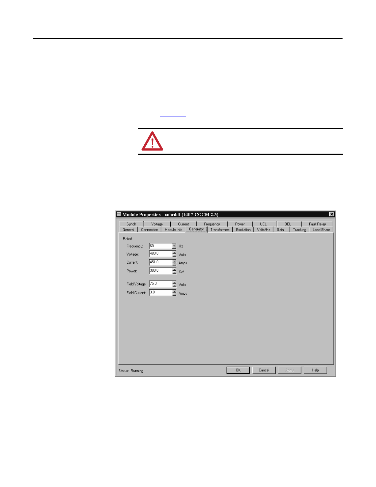
Chapter 4 CGCM Unit Configuration
RSLogix 5000 software performs configuration data checking as specified by the
limits shown in the data tables. The data checking verifies that the entry is within
range for the device, however, it does not verify that it is reasonable for the
application. You must be sure that the entry is reasonable for the specific
application. If you enter an out-of range parameter in a Configuration tab, a
message box reports the error and the appropriate limits.
Refer to Chapter
6 for information on the limits specified by the data tables.
WARNING: Data limit checking does not ensure values are appropriate
for the application.
Generator Tab
The Generator tab is used to configure the unit to the design ratings of the
generator. Enter the generator’s nameplate ratings in the appropriate fields of the
Generator tab.
Rated Frequency - Sets the generator's rated frequency in Hz. Sets the value of tag
GenRatedFreq in the Configuration table.
Rated Voltage - Sets the generator's rated line-to-line voltage in volts AC. Sets the
value of tag GenRated_V in the Configuration table.
Rated Current - Sets the generator's rated current in amperes AC. Sets the value
of tag GenRated_I in the Configuration table.
76 Rockwell Automation Publication 1407-UM001G-EN-P - April 2013
Page 77

CGCM Unit Configuration Chapter 4
Open Delta
Open Delta
12000.0
12000.0
12000.0
Rated Power - Sets the generator's rated power in Watts. Sets the value of tag
GenRated_W in the Configuration table.
Rated Field Voltage - Sets the generator exciter's rated field voltage while the
generator is operating at rated voltage, kW, and kVAR. Sets the value of tag
GenRatedExcV in the Configuration table.
Rated Field Current - Sets the generator exciter's rated field current, in amperes
DC. This is the current that must be supplied to the exciter while the generator is
operating at rated voltage, kW, and kVAR. Sets the value of tag GenRatedExcI in
the Configuration table.
Transformers Tab
The Transformers tab is used to match the unit with the configuration of the
generator voltage and current sensing transformers. To configure the Transformer
tab, you must know the system wiring configuration. The settings entered in the
Transformers tab must correspond to the actual wiring configuration.
Please refer to Chapter
2, Installation, for information on various wiring
configurations.
Please refer to the VT and CT manufacturer’s data for assistance in entering the
correct primary and secondary voltages.
Rockwell Automation Publication 1407-UM001G-EN-P - April 2013 77
Page 78

Chapter 4 CGCM Unit Configuration
• Generator VT Configuration - The generator VT configuration selections
are (1) single-phase, (2) two-transformer open delta, (3) three-wire wye,
and (4) four-wire wye. Use the two-transformer open delta setting for any
delta configuration. This parameter is stored in the tag GenVT_Config in
the configuration table.
• Generator VT Primary Voltage - The primary voltage rating of the
generator voltage transformer is stored in tag GenVT_Pri_V in the
configuration table.
• Generator VT Secondary Voltage - The secondary voltage rating of the
generator voltage transformer connected to V Gen A, V Gen B, and V Gen
C, (and V Gen N for wye configurations) of the CGCM unit. This
parameter is stored in tag GenVT_Sec_V in the configuration table.
• Bus VT Configuration - The bus VT configuration selections are (1)
single-phase, (2) two-transformer open delta, (3) three-wire wye, (4)
four-wire wye, and (5) dual breaker. This parameter is stored in the tag
BusVT_Config in the configuration table. For applications that require
synchronizing to one of two busses, dual breaker must be selected.
• Bus A VT Primary Voltage - The primary voltage rating of the bus voltage
transformer is stored in tag BusA_VT_Pri_V in the configuration table.
• Bus A VT Secondary Voltage - The secondary voltage rating of the bus
voltage transformer connected to V Bus A, V Bus B, and V Bus C (and V
Gen N for wye configurations) of the CGCM unit. This parameter is
stored in tag BusA_VT_Sec_V in the configuration table.
• Bus B VT Primary Voltage - The primary voltage rating of the second bus
voltage transformer when dual breaker bus VT configuration is selected.
This parameter is stored in tag BusB_VT_Pri_V in the configuration
table.
• Bus B VT Secondary Voltage - The secondary voltage rating of the second
bus voltage transformer connected to V Bus B, and V Bus N of the CGCM
unit. This parameter is stored in tag BusB_VT_Sec_V in the
configuration table.
The Bus B VT settings are used only by the CGCM unit if the Bus VT
configuration selection is dual breaker.
• Generator CT Primary Current - Is the primary current rating of the
generator current transformers. This parameter is stored in tag
GenCT_Pri_I in the configuration table.
• Generator CT Secondary Current - The secondary current rating of the
generator current transformers connected to the CGCM unit’s terminals
I1, I2, and I3. This parameter is stored in tag GenCT_Sec_I in the
configuration table.
• Cross Current CT Primary Current - The primary current rating of the
cross current generator current transformer. This parameter is stored in tag
CCCT_Pri_I in the configuration table. It is used for monitoring
generator reactive current in paralleling applications.
78 Rockwell Automation Publication 1407-UM001G-EN-P - April 2013
Page 79

CGCM Unit Configuration Chapter 4
EXAMPLE
• Cross Current CT Secondary Current - The secondary current rating of
the cross current generator current transformer connected to the CGCM
unit terminals ID (+) and ID (-).This parameter is stored in tag
CCCT_Sec_I in the configuration table. It is used for monitoring
generator reactive current in paralleling applications.
As an example, consider a generator rated at 12,470V and 450 A. VTs
with ratios of 100:1 and CTs with ratios of 500:5 are used. The
appropriate settings for this configuration are:
• Generator VT Primary Voltage = 12,000
• Generator VT Secondary Voltage = 120
• Generator CT Primary Current = 500
• Generator CT Secondary Current = 5
Excitation Tab
The Excitation tab is used to configure the unit’s settings related to operation and
protection of the exciter.
• Soft Start Initial Voltage - The generator voltage setpoint that is applied
immediately after enabling the CGCM unit excitation output. This
parameter is stored in tag SoftStart_InitLevel in the Configuration table.
Its value is a percentage of the nominal generator rated voltage. Take care
to set this parameter higher than the generator residual voltage.
Rockwell Automation Publication 1407-UM001G-EN-P - April 2013 79
Page 80

Chapter 4 CGCM Unit Configuration
TIP
• Soft Start Time - The desired time to ramp up from the Soft Start Initial
Voltage to the nominal generator output voltage. This parameter is stored
in tag SoftStartTime in the Configuration table and is expressed in
seconds.
• Over-excitation Voltage Setpoint - Establishes the over-excitation voltage
setpoint used by the CGCM unit. This setpoint is stored in tag
OvrExcV_Setpt in the configuration table and scaled in volts.
• Over-excitation Time Delay - Establishes the time to annunciate a fault
once the over-excitation voltage setpoint has been exceeded. This setpoint
is stored in tag OvrExcV_TimeDly in the configuration table and scaled
in seconds.
Coordinate the Over-excitation voltage setpoint and time delay
settings with the OEL function settings to protect the exciter from
overheating while avoiding nuisance tripping from normal field
forcing during transient conditions.
• Loss of Excitation Current Setpoint - Establishes the level of excitation
current that is considered to be a minimum needed to maintain generator
synchronization when in parallel with other power sources such as a utility
grid. This setpoint is stored in tag LossExc_I_Setpt in the configuration
table and scaled in amperes. Excitation current in excess of the loss of
excitation current setpoint enables loss of sensing protection.
• Loss of Excitation Current Delay - Establishes the amount of time in
seconds that the excitation current must be continually below the Loss of
Excitation Current Setpoint before the CGCM unit annunciates a loss of
excitation fault. This setpoint is stored in tag LossExc_I_TimeDly in the
configuration table
• Rotating Diode Fault Main Pole - Indicates the number of poles of the
main field of the generator. Stored in tag MainPole in the configuration
table.
• Rotating Diode Fault Exciter Pole – Indicates the number of poles of the
exciter field of the generator. Stored in tag ExciterPole in the
configuration table.
• Rotating Diode Fault Open Diode Level - Establishes the percent ripple at
which the rotating diode monitor alarm turns on when an open diode
condition occurs. This parameter is stored in tag
OpenDiodeMonitorLevel in the configuration table and is expressed in
percent of maximum ripple current.
• Rotating Diode Fault Shorted Diode Level - Establishes the percent ripple
at which the rotating diode monitor alarm turns on in the event a shorted
diode condition occurs. Tag ShortedDiodeMonitorLevel in the
configuration table stores this value, expressed in percent of maximum
ripple current.
80 Rockwell Automation Publication 1407-UM001G-EN-P - April 2013
Page 81

CGCM Unit Configuration Chapter 4
TIP
• Rotating Diode Fault Delay - Establishes the time duration that the ripple
current must be at or above the fault level before the CGCM unit
annunciates a rotating diode fault. Tag DiodeMonitorTimeDelay in the
configuration table stores this value, expressed in seconds.
Refer to Chapter 5 for more information on configuring rotating
diode protection parameters.
• Excitation Select – Selects the excitation power source. This parameter is
stored in the Boolean tag PMG_Shunt_Select in the Configuration table.
In this tag, 0 = PMG, 1 = Shunt. Select PMG to enable the loss of PMG
sensing. Select Shunt for obtaining excitation power from the generator’s
terminals and for systems using series boost.
• PMG Phase Select – Establishes whether the excitation power source to
the CGCM unit is single or 3-phase, to assure correct operation of the loss
of PMG sensing function. This parameter is stored in the Boolean tag
PMG_1Ph_3Ph_Select in the Configuration table. In this tag, 0 = single
phase, 1 = 3-phase.
Related Parameters:
• Over-excitation voltage protection – Over-excitation limiting (OEL)
configuration parameters
• GenRated_V
Rockwell Automation Publication 1407-UM001G-EN-P - April 2013 81
Page 82

Chapter 4 CGCM Unit Configuration
Volts/Hz Tab
The Volts/Hz tab is used to configure the unit’s settings related to operation of
the Volts/Hz compensation function. The parameters define a curve, which
determines the Volts/Hz response.
• Volts per Hertz Upper Knee Frequency - Establishes the frequency at
which the V/Hz characteristic starts to reduce the generator voltage as a
function of generator frequency. Tag Vp e rH z _ H i K n e eF r e q in the
configuration table stores this value, expressed in Hertz. The upper knee
frequency must be greater than the lower knee frequency.
• Volts per Hertz Upper Slope - Establishes the rate at which the V/Hz
characteristic reduces the generator voltage as a function of generator
frequency between the upper and lower knee frequencies. Tag
Vp e r H z _ H i S l o p e in the configuration table stores this value, expressed as
a number that reflects per unit change in voltage for each per unit change
in frequency.
• Volts per Hertz Lower Knee Frequency - Establishes the frequency at
which the V/Hz characteristic starts to reduce the generator voltage at the
lower slope rate as a function of generator frequency. Tag
Vp e r H z _ L o K n e e Fr e q in the configuration table stores this value,
expressed in Hertz. The lower knee frequency must be less than the upper
knee frequency.
82 Rockwell Automation Publication 1407-UM001G-EN-P - April 2013
Page 83

CGCM Unit Configuration Chapter 4
• Volts per Hertz Lower Slope - Establishes the rate at which the V/Hz
characteristic reduces the generator voltage as a function of generator
frequency below the Lower Knee Frequency setting. Tag
Vp e r H z _ L o S l o p e in the configuration table stores this value, expressed as
a number that reflects per unit change in voltage for each per unit change
in frequency.
• The Validate and graph button becomes active when a parameter has been
changed. When clicked, the V/Hz curve established by the knee and slope
values is plotted in the Volts/Hz tab.
Related Parameters:
• GenRated_V
• GenRatedFreq
OEL Tab
The OEL tab is used to configure the unit’s settings related to operation of the
Over-excitation Limiting (OEL) function. The values entered in this tab
establish the thresholds and time delays that determine the behavior of the
over-excitation limiting function. See the generator manufacturer’s data sheets for
information such as, exciter full-load and forcing current for setting both online
and offline conditions.
Refer to Chapter
3 for more information on the operation of the OEL function.
Rockwell Automation Publication 1407-UM001G-EN-P - April 2013 83
Page 84

Chapter 4 CGCM Unit Configuration
FIELD CURRENT
TIME IN SECONDS
High
Current
Time
0…10 seconds
CONTINUOUS
Medium
Current
Time
0…120 seconds
Low
Current
Level
0.0…15 A dc
Medium
Current
Level
0.0… 20 A dc
High
Current
Level
0.0…30 A dc
A
B
C
FIELD CURRENT
TIME IN SECONDS
High
Current
Time
CONTINUOUS
0…10 seconds
Low
Current
Level
0…15 A dc
High
Current
Level
0…30 A dc
D
E
• Over-excitation Limiting Enable – Select this check box to enable
over-excitation limiting. Tag OEL_En in the configuration table stores
this parameter. In addition to selecting the check box, which sets the
OEL_En tag in the configuration table, the OEL_En tag in the Output
(Scheduled Write) Data table must also be set to enable this function. In
Series B deices with firmware revision 3.3 or earlier, the OEL limiter
operates if either box is checked or the OEL_En tag in the Output
(Scheduled Write) Data table is set.
• The tags listed below determine the points shown in the OEL
configuration diagrams below. These tags are in the configuration table
and are set by the like-named fields in the OEL tab. They are expressed as
amperes and seconds, respectively.
Figure 37 - Online OEL Configuration
84 Rockwell Automation Publication 1407-UM001G-EN-P - April 2013
– Point A is defined by tags OEL_OnlineHiSetpt and
OEL_OnlineHiTimeDly
– Point B is defined by OEL_OnlineMedSetpt and
OEL_OnlineMedTimeDly
– Point C is defined by OEL_OnlineLoSetpt
Figure 38 - Offline OEL Configuration
– Point D is defined by OEL_OfflineHiSetpt and
OEL_OfflineHiTimeDly
– Point E is defined by OEL_OfflineLoSetpt
• Online/Offline graph button - Toggles to show online or offline OEL
characteristics. The graph pictorially represents the OEL settings.
Page 85

CGCM Unit Configuration Chapter 4
• Validate and Graph button – Updates the graph in the OEL tab after
entering new values.
Related Parameters
• GenRatedExcI
• OEL_En tag in the Output table
UEL Tab
The UEL tab is used to configure the unit’s settings related to operation of the
Under-excitation Limiting (UEL) function. The values entered in this tab
establish break points in a piecewise linear curve that defines the characteristic
curve for this function. See the generator manufacturer’s data for the proper
setting information.
Refer to Chapter
3 for more information on the operation of the UEL function.
• Under-excitation Limiting Enable – Select this check box to enable
over-excitation limiting. Tag UEL_En in the configuration table stores
this parameter. In addition to selecting the check box, which sets the
UEL_En tag in the configuration table, the UEL_En tag in the Output
(Scheduled Write) Data table must also be set to enable this function. In
Series B deices with firmware revision 3.3 or earlier, the UEL limiter
operates if either the enable box is checked or the UEL_En tag in the
Output (Scheduled Write) Data table is set.
Rockwell Automation Publication 1407-UM001G-EN-P - April 2013 85
Page 86

Chapter 4 CGCM Unit Configuration
1
2
3
4
5
Real Power, Watts
Reactive Power, VARs
• The tags listed below determine the points shown in the UEL
configuration diagrams below. These tags are in the configuration table
and are set by the like-named fields in the UEL tab. Configure the VAR
and Watt tags with increasing real power values in point 1 through point x.
These tags define the curve breakpoints. As shown, the curve continues
horizontally left from point 1 and vertically up from point 5. The tags are
expressed in Watts or VARs respectively.
– Point 1 is defined by tags UEL_Curve_W_Pt1 and
UEL_Curve_VAR_Pt1
– Point 2 is defined by tags UEL_Curve_W_Pt2 and
UEL_Curve_VAR_Pt2
– Point 3 is defined by tags UEL_Curve_W_Pt3 and
UEL_Curve_VAR_Pt3
– Point 4 is defined by tags UEL_Curve_W_Pt4 and
UEL_Curve_VAR_Pt4
– Point 5 is defined by tags UEL_Curve_W_Pt5 and
UEL_Curve_VAR_Pt5
• Validate and Graph button – Updates the graph in the UEL tab after
entering new values.
Related Parameters
86 Rockwell Automation Publication 1407-UM001G-EN-P - April 2013
• UEL_En tag in the Output table
Page 87

CGCM Unit Configuration Chapter 4
Gain Tab
The Gain tab is used to configure the unit’s gain parameters necessary for the
operation of the excitation control. Except as otherwise noted, gain parameters
are unitless.
Appendix
B provides additional information regarding the mathematical models
used in the unit.
The parameters in the Gain tab are stored in the Unscheduled Write table and are
not automatically written to the unit.
Refer to Chapter
6 for a discussion of user programming necessary to transfer
these parameters.
AVR/FCR Control
The AVR/FCR gains determine the response of the main control loop of the
voltage regulation function. The PID calculator software available in the Tools
folder on the RSLogix 5000 software installation CDs can be used to assist in
determining appropriate initial AVR gain settings for Kp, Ki, Kd, and Kg. These
settings can be fine tuned during system startup.
Please refer to Chapter
Rockwell Automation Publication 1407-UM001G-EN-P - April 2013 87
5 for more information on tuning the regulator gains.
Page 88

Chapter 4 CGCM Unit Configuration
• Proportional Gain Kp - Sets the proportional gain, which determines the
characteristic of the dynamic response to changes in generator voltage. If
the transient response has too much overshoot, decrease Kp. If the
transient response is too slow, with little or no overshoot, then increase Kp.
The tag AVR_FCR_Kp in the Unscheduled Write table stores this
parameter.
• Integral Gain Ki – Sets the integral gain. If the time to reach steady state is
too long, increase Ki. The tag AVR_FCR_Ki in the Unscheduled Write
table stores this parameter.
• Derivative Gain Kd – Sets the derivative gain. To improve the transient
response to a step change, increase Kd. If there is too much jitter in the
steady-state voltage, decrease Kd. The tag AVR_FCR_Kd in the
Unscheduled Write table stores this parameter.
• Time Constant Td - The filtering time constant, Td, is used to remove the
noise effect on the numerical differentiation. The tag AVR_FCR_Td in
the Unscheduled Write table stores this parameter, expressed in seconds.
• FCR Overall Gain Kg - Sets the overall gain of the voltage regulator in
FCR mode. It determines the characteristic of the dynamic response to a
change in the CGCM unit output current. The tag FCR_Kg in the
Unscheduled Write table stores this parameter.
• AVR Overall Gain Kg – Sets the overall gain of the voltage regulator in
AVR mode. It determines the characteristic of the dynamic response to a
change in the voltage of the generator. The tag AV R _ K g in the
Unscheduled Write table stores this parameter.
• Voltage Matching Gain – This parameter is not used. Set to zero. The tag
V_Match_Gain in the Unscheduled Write table stores this parameter.
88 Rockwell Automation Publication 1407-UM001G-EN-P - April 2013
Page 89

CGCM Unit Configuration Chapter 4
Power Factor Control
The Power Factor Control gains determine the response of the power factor
control loop for the voltage regulation function when in PF mode. These settings
can be adjusted during system startup.
Please refer to Chapter
5 for more information on tuning the power factor
control gains.
• Integral Gain Ki - Sets the integral gain. Generally if the time to reach
steady state is too long, increase Ki. The tag PF_Ki in the Unscheduled
Write table stores this parameter.
• Overall Gain Kg - Sets the overall gain, which determines the characteristic
of the dynamic response to changes in power factor. If the transient
response has too much overshoot, decrease Kg. If the transient response is
too slow, with little or no overshoot, then increase Kg. The tag PF_Kg in
the Unscheduled Write table stores this parameter.
VAR Con tr ol
The VAR Control gains determine the response of the VAR control loop for the
voltage regulation function when in VAR mode. These settings can be adjusted
during system startup.
Please refer to Chapter
5 for more information on tuning the VAR control gains.
• Integral Gain Ki - Sets the integral gain. Generally if the time to reach
steady state is too long, increase Ki. The tag VA R_ Ki in the Unscheduled
Write table stores this parameter.
• Overall Gain Kg - Sets the overall gain, which determines the characteristic
of the dynamic response to changes in VARs. If the transient response has
too much overshoot, decrease Kg. If the transient response is too slow, with
little or no overshoot, then increase Kg. The tag VAR _ K g in the
Unscheduled Write table stores this parameter.
Over-excitation Limiting
The OEL gains determine the response of the OEL control loop for the voltage
regulation function when OEL is active. These settings can be adjusted during
system startup.
Please refer to Chapter
5 for more information on tuning the OEL control gains.
• Integral Gain Ki - Sets the integral gain. If the time to reach steady state is
too long, increase Ki. The tag OEL_Ki in the Unscheduled Write table
stores this parameter.
• Overall Gain Kg - Sets the overall gain, which determines the characteristic
of the dynamic response when OEL is active. If the transient response has
too much overshoot, decrease Kg. If the transient response is too slow, with
little or no overshoot, then increase Kg. The tag OEL_Kg in the
Unscheduled Write table stores this parameter.
Rockwell Automation Publication 1407-UM001G-EN-P - April 2013 89
Page 90

Chapter 4 CGCM Unit Configuration
Under-excitation Limiting
The UEL gains determine the response of the UEL control loop for the voltage
regulation function when UEL is active. These settings can be adjusted during
system startup.
Please refer to Chapter
5 for more information on tuning the UEL control gains.
• Integral Gain Ki - Sets the integral gain. If the time to reach steady state is
too long, increase Ki. The tag UEL_Ki in the Unscheduled Write table
stores this parameter.
• Overall Gain Kg - Sets the overall gain, which determines the characteristic
of the dynamic response when UEL is active. If the transient response has
too much overshoot, decrease Kg. If the transient response is too slow, with
little or no overshoot, then increase Kg. The tag UEL_Kg in the
Unscheduled Write table stores this parameter.
Other Gains
The remaining three gains are stored in the Configuration table and can only be
written to the CGCM unit when excitation is disabled.
Please refer to Chapter
6 for more information.
• AVR/FCR Control Auxiliary Gain - Sets the influence of the auxiliary
input on the AVR/FCR operating setpoint. The units are percent of rated
generator voltage or excitation field current, as applicable, per auxiliary
input volt. The tag AV R _ F C R A u x G a i n in the Configuration table stores
this parameter.
• PF/VAR Auxiliary Gain - Sets the influence of the auxiliary input on the
VAR/PF operating setpoint. The units for the var controller are percent of
rated generator KVA. For PF control, the units are 0.01 PF per volt. A
setting of 5 results in the regulated PF being changed by 0.05 for each volt
applied to the auxiliary input. The tag PF_VARAuxGain in the
Configuration table stores this parameter.
• Cross-current Gain - sets the gain of the cross-current input. The measured
cross-current value is multiplied by this setting. This setting determines
the change in voltage setpoint expressed in percent of rated voltage for a
change in kVARs equal to the rated generator kVA. This parameter adjusts
the characteristic of VAR sharing between machines connected in the
cross-current compensation method of VAR sharing. A setting of 5, for
example, results in the voltage setpoint being changed by 5% of rated
voltage for a change in kVARs equal to the rated kVA. The tag
CrossCurrentGain in the Configuration table stores this parameter.
Related Parameters
• GenRated_V
• GenRated_I
• GenRatedExcI
90 Rockwell Automation Publication 1407-UM001G-EN-P - April 2013
Page 91

CGCM Unit Configuration Chapter 4
Tracking Tab
The Tracking tab is used to configure the unit’s internal and redundant tracking
parameters. Enter the internal tracking, redundant tracking, and traverse rates in
the appropriate fields of the Tracking tab.
Rockwell Automation Publication 1407-UM001G-EN-P - April 2013 91
Page 92

Chapter 4 CGCM Unit Configuration
Internal Tracking
• Enable internal tracking - This checkbox sets the Boolean tag
Internal_Tracking_En in the Configuration data table. When the value
of this tag is 1, internal tracking between voltage regulating modes is
enabled and the Traverse Rates are enabled. If the tag value is 0, both the
Traverse Rates and tracking between regulation modes is disable.
• Internal Tracking Rate - This setting changes the rate at which the internal
tracking function matches the non-active excitation control modes to the
active excitation control mode. This sets the value of the
InternalTrackRate tag in the Configuration table, expressed in seconds.
• Internal Tracking Delay - This setting adjusts the delay in the internal
tracking function. This sets the value of the InternalTrackDelay tag in the
Configuration table, expressed in seconds. Its purpose is to reduce the
likelihood that the short-term response of the active regulating mode to an
upset is transferred to a new mode of operation when the mode is
switched. If the internal tracking delay is too short, the transient response
to an upset is transferred to the new operating mode. Conversely, if the
tracking delay is set too long, there is a risk of an old operating point being
transferred to the new operating mode, resulting in an undesirable bump.
AVR Setpoint
Setpoint / Regulator Output
FCR
Setpoint
Regulator
Output
Internal
Tracking
An example of how these parameters affect tracking is shown in the Internal
Tr a ck i ng graph. In this example, a loss of sensing causes a full-scale regulator
output. The internal tracking delay permits FCR mode to begin operation at the
output level prior to the loss of sensing.
Figure 39 - Internal Tracking
Internal
<
Tracking Delay
Internal Tracking
Delay
Return from Tracked
Value to FCR Setpoint
Internal Tracking
Delay
92 Rockwell Automation Publication 1407-UM001G-EN-P - April 2013
4x Internal
Tracking Delay
Upset
Rapid Decline to
Tracked Value
Mode Switched
to FCR
Time
Page 93

CGCM Unit Configuration Chapter 4
TIP
Increasing the internal tracking rate makes the tracking function less responsive to
changes in the regulator output by reducing the slope of the tracking function.
Increasing the tracking delay offsets the tracking response to the right in the
figure. In the example above, if the internal tracking delay were reduced, it is likely
that the FCR mode setpoint has started at full regulator output, and recovery to
the desired operation has been delayed.
Redundant Tracking
Redundant tracking is enabled whenever two CGCM units are configured
in a Redundant mode and both are operational. Redundant tracking
parameters have no effect on a CGCM that is not part of a redundant
pair.
• Redundant Tracking Rate - This setting adjusts the rate at which the
tracking function of the redundant CGCM unit matches its regulator
operating point to that of the active CGCM unit. This sets the value of the
RedndtTrackRate tag in the Configuration table, expressed in seconds per
full-scale excursion of the regulator output from zero to the rated
generator field current.
• Redundant Tracking Delay - This setting adjusts the delay in the
redundant tracking function. This sets the value of the
RedndtTrackDelay tag in the Configuration table, expressed in seconds.
Its purpose is to reduce the likelihood that the short-term response of the
active CGCM unit’s Regulating mode to an upset will be transferred to the
back-up CGCM unit when it becomes primary.
The redundant tracking function performs in a similar fashion to the internal
tracking example above. Increasing the redundant tracking rate makes the
tracking function less responsive to changes in the regulator output by reducing
the slope of the tracking function. Increasing the tracking delay offsets the
tracking response to the right in the figure.
Tr av er se R at es
These parameters adjust how fast the regulator changes its operating point from
one setpoint, the tracking value, to another when changing regulator operating
modes. In general, the lower the rate, the faster the regulator operating point
changes. A value of 200 puts the regulator in Hold mode and prevents the field
current from changing when the Regulator Operating mode is changed.
Please refer to Chapter
3 for more information.
• AVR Control Traverse Rate – Sets tag AV R _Tr a v e r s e _ R a t e in the
Configuration table. This parameter determines the time measured in
seconds for the setpoint to move from zero to the rated generator voltage.
It determines how fast the regulator changes the voltage setpoint from the
tracking value to the operating setpoint when the Regulator Operating
mode changes to AVR.
Rockwell Automation Publication 1407-UM001G-EN-P - April 2013 93
Page 94

Chapter 4 CGCM Unit Configuration
VAR Mode PF Mode
Excitation Current
VARs
Power Factor
Generator Voltage
PF Mode Setpoint
PF Mode Internal
Tracking Setpoint =
Measured PF
PF Mode Traverse Rate
Determines Transition to New
Mode's Operating Point
VAR Internal
Tracking Setpoint
FCR Internal
Tracking Setpoint
PF is New
Process Variable
VARs are Old Process
Variable
• Power Factor Traverse Rate - Sets tag PF_Traverse_Rate in the
Configuration table. This parameter determines the time measured in
seconds for the PF setpoint to move from 0.50 lagging to 0.50 leading or
vice versa. It determines how fast the regulator changes the power factor
setpoint from the tracking value to the operating setpoint when the
Regulator Operating mode changes to PF.
• VAR Control Traverse Rate - Sets tag VA R_ Tr a v e rs e_ R a te in the
Configuration table. This parameter determines the time measured in
seconds for the setpoint to move from zero to the rated generator KVA. It
determines how fast the regulator changes the VAR setpoint from the
tracking value to the operating setpoint when the Regulator Operating
mode changes to VAR.
• Manual Control (FCR) Traverse Rate - Sets tag FCR_Traverse_Rate in
the Configuration table. This parameter determines the time measured in
seconds for the setpoint to move from zero to the rated exciter current. It
determines how fast the regulator changes the field current setpoint from
the tracking value to the operating setpoint when the Regulator Operating
mode changes to FCR.
The following diagram shows the function of internal tracking and traverse rates
on a switch from VAR to PF operating modes.
Figure 40 - Internal Tracking and Traverse Rates
94 Rockwell Automation Publication 1407-UM001G-EN-P - April 2013
Page 95

CGCM Unit Configuration Chapter 4
Related Parameters
• Internal tracking – GenRatedExcI
• Traverse rates – GenRated_V, GenRated_I, GenRatedExcI
Synch Tab
The Synch tab is used to configure the unit’s parameters related to the
synchronizing function of the CGCM unit.
Synchronization Limits
• Frequency Match - Establishes the acceptance window for frequency
matching, defined by Configuration table tags SyncFreqLoLimit and
SyncFreqHiLimit. These tags are set by using the Lower Limit and Upper
Limit fields in the Synch tab and are expressed in Hertz.
• Voltage Match - Establishes the acceptance window for voltage matching,
defined by Configuration table tags SyncV_LoLimit and
SyncV_HiLimit. These tags are set by using the Lower Limit and Upper
Limit fields in the Synch tab and are expressed in percent of rated
generator voltage.
• Phase Match - Establishes the acceptance window for phase matching,
defined by Configuration table tags SyncPhLoLimit and
SyncPhHiLimit. These tags are set by using the Lower Limit and Upper
Limit fields in the Synch tab and are expressed in degrees.
Rockwell Automation Publication 1407-UM001G-EN-P - April 2013 95
Page 96

Chapter 4 CGCM Unit Configuration
TIP
• Acceptance Delay - Establishes the time that all sync parameters must be
continuously within their respective acceptance windows to permit closing
the breaker. The Configuration table tag SynchAcceptDly stores this
value, expressed in seconds.
Bus A Offsets
• Voltage multiplier - Establishes a factor by which the Bus A voltage is
scaled during synchronization. It can be used to compensate for
transformer ratio differences between the generator and bus voltages. For
example, if the generator nominal voltage is 4160V and the nominal Bus A
voltage is 12,480V (each measured line-to-line), a voltage multiplier value
of 0.333 permits voltage matching during synchronization. Configuration
table tag BusA_V_Scaler stores this parameter.
• Phase - Establishes an offset angle added to the measured Bus A phase
angle. It can be used to compensate for phase shift across transformers or
between delta and wye connected systems.
As an example, consider the system shown in Voltage and Current
Connection for Four-wire Wye Bus and Two (or three) Transformer Delta
Generator System on page 24.
When a generator with three-wire (delta) metering is synchronized to a
bus with four-wire (wye) metering, set the phase offset to 30° to
compensate for the 30° lag between the delta and wye systems.
Configuration table tag BusA_PhOffset stores this parameter, expressed
in degrees.
Bus B Offsets
• Voltage multiplier - Establishes a factor by which the Bus B voltage is
scaled during synchronization. It can be used to compensate for
transformer ratio differences between the generator and bus voltages.
Configuration table tag BusB_V_Scaler stores this parameter.
• Phase - Establishes an offset angle added to the measured Bus B phase
angle. It can be used to compensate for phase shift across transformers or
between delta and wye connected systems. Configuration table tag
BusB_PhOffset stores this parameter, expressed in degrees.
The Bus A examples also apply to Bus B.
96 Rockwell Automation Publication 1407-UM001G-EN-P - April 2013
Page 97

CGCM Unit Configuration Chapter 4
IMPORTANT
IMPORTANT
Table 4 provides a guide for adjusting phase offset for wiring
configurations shown in Chapter 2
configurations are possible. It is your responsibility to determine and
verify phase offset values for wiring configurations that are not depicted
in this manual.
Table 4 - Phase Offset Guide
Generator Bus Phase Shift Offset in CGCM Synch Tab
Single phase (line-to-line) Dual breaker (line-to-neutral) -30
Single phase (line-to-line) Four-wire wye -30
Open delta Dual breaker (line-to-neutral) -30
Open delta Four-wire wye -30
Three-wire wye Dual breaker (line-to-line) -60
Three-wire wye Dual breaker (line-to-neutral) -30
Three-wire wye Four-wire wye -30
Four-wire wye Dual breaker (line-to-line) -30
Four-wire wye Single (connected line-to-line) 30
Four-wire wye Open delta 30
Four-wire wye Three-wire wye 30
, Installation. Other wiring
Dead Bus Limits
The dead bus limits define the acceptance windows for generator frequency and
voltage used by the CGCM unit when closing the breaker into a dead bus. The
following Configuration tab fields specify the acceptance windows. These fields
set the related tags in the Configuration table.
• Min Frequency - Tag DeadbusGenFreqLoLimit, expressed in Hertz
• Max Frequency - Tag DeadbusGenFreqHiLimit
• Min Voltage - Tag DeadbusGenV_LoLimit, expressed in volts
• Max Voltage - Tag DeadbusGenV_HiLimit
Prior to Host FRN 4.9, regardless of the setting of the
DeadbusGenFreqLoLimit parameter, the CGCM unit disables
synchronization when the generator frequency is below 45 Hz.
Rotation
• Generator – Specifies the generator phase rotation. Configuration table
tag GenRotABC_ACB_Select stores this value. 0 = ABC, 1 = ACB
• Bus – Specifies the bus phase rotation. Configuration table tag
BusRotABC_ACB_Select stores this value. 0 = ABC, 1 = ACB
Rockwell Automation Publication 1407-UM001G-EN-P - April 2013 97
Page 98

Chapter 4 CGCM Unit Configuration
Related Parameters
• GenVT_Config
• BusVT_Config
• GenRated_V
Load Share Tab
The Load Share tab is used to configure the unit’s parameters related to the real
power load sharing function of the unit.
• Full Scale Voltage - Sets the load share output voltage when the generator
is producing rated real power. The tag LS_FS_V in the configuration table
stores this value, expressed in volts.
• Limit - Sets the maximum per unit load share error reported to the host
controller. The tag LSLimit in the configuration table stores this value,
expressed in per unit power.
• Rate - Sets the maximum change in the load share error per CGCM unit
update cycle. The tag LSRate in the configuration table stores this value,
expressed in seconds per rated watts.
Related Parameters
• GenRated_W
98 Rockwell Automation Publication 1407-UM001G-EN-P - April 2013
Page 99

CGCM Unit Configuration Chapter 4
Voltage Tab
The Voltage tab is used to configure the unit’s parameters related to the voltage
protection and compensation functions.
Over-voltage
• Setpoint - Establishes the over-voltage setpoint used by the CGCM unit.
This setpoint is stored in tag Ovr_V_Setpt in the configuration table and
scaled in per cent rated generator volts.
• Delay - Establishes the time the generator voltage must be above the
over-voltage setpoint before the CGCM unit annunciates an over-voltage
fault. This setpoint is stored in tag Ovr_V_TimeDly in the configuration
table and scaled in seconds.
Rockwell Automation Publication 1407-UM001G-EN-P - April 2013 99
Page 100

Chapter 4 CGCM Unit Configuration
Un de r- vo lt ag e
• Setpoint - Establishes the under-voltage setpoint used by the CGCM unit.
This setpoint is stored in tag Undr_V_Setpt in the configuration table
and scaled in per cent rated generator volts.
• Delay - Establishes the time the generator voltage must be below the
under-voltage setpoint before the CGCM unit annunciates an
under-voltage fault. This setpoint is stored in tag Undr_V_TimeDly in
the configuration table and scaled in seconds.
Compensation Settings
• Droop Percentage - Establishes the voltage droop level at rated load when
operating in Voltage Droop (reactive current compensation) mode. This
setting determines the change in voltage setpoint expressed in percent of
rated voltage. A setting of 5, for example, results in the voltage setpoint
being changed by 5% of rated voltage for a change in kVARs equal to the
rated kVA. The tag V_DroopSetpt in the Configuration table stores this
parameter.
• Line Drop Voltage Compensation - Establishes the output voltage increase
at rated current. Tag LineDropComp in the Configuration table stores
this parameter.
Related Parameters
• GenRated_V
• GenRated_I
• GenRated_W
• SoftStartTime
• EngineIdle
100 Rockwell Automation Publication 1407-UM001G-EN-P - April 2013
 Loading...