

Page 1

Bulletin 1404 Powermonitor 3000
Catalog Numbers
User Manual
1404-M4, 1404-M5, 1404-M6, 1404-M8
Page 2
Important User Information
Solid state equipment has operational characteristics differing from those of electromechanical equipment. Safety Guidelines
for the Application, Installation and Maintenance of Solid State Controls (publication SGI-1.1
Automation sales office or online at http://www.rockwellautomation.com/literature/
between solid state equipment and hard-wired electromechanical devices. Because of this difference, and also because of the
wide variety of uses for solid state equipment, all persons responsible for applying this equipment must satisfy themselves that
each intended application of this equipment is acceptable.
In no event will Rockwell Automation, Inc. be responsible or liable for indirect or consequential damages resulting from the use
or application of this equipment.
The examples and diagrams in this manual are included solely for illustrative purposes. Because of the many variables and
requirements associated with any particular installation, Rockwell Automation, Inc. cannot assume responsibility or liability for
actual use based on the examples and diagrams.
No patent liability is assumed by Rockwell Automation, Inc. with respect to use of information, circuits, equipment, or software
described in this manual.
Reproduction of the contents of this manual, in whole or in part, without written permission of Rockwell Automation, Inc., is
prohibited.
Throughout this manual, when necessary, we use notes to make you aware of safety considerations.
WARNING
Identifies information about practices or circumstances that can cause an explosion in a hazardous environment,
which may lead to personal injury or death, property damage, or economic loss.
available from your local Rockwell
) describes some important differences
IMPORTANT
ATTENTION
SHOCK HAZARD
BURN HAZARD
Rockwell Automation, Allen-Bradley, TechConnect, PLC-5, SLC, SLC 500, SLC 5/03, PanelView, Powermonitor 3000, ControlLogix, Rockwell Software, RSNetworx for DeviceNet, RSNetworx for
ControlNet, RSLogix 5000, RSEnergyMetrix, RSPower, RSPowerPlus, and RSLin are trademarks of Rockwell Automation, Inc.
Trademarks not belonging to Rockwell Automation are property of their respective companies.
Identifies information that is critical for successful application and understanding of the product.
Identifies information about practices or circumstances that can lead to personal injury or death, property damage,
or economic loss. Attentions help you identify a hazard, avoid a hazard, and recognize the consequence
Labels may be on or inside the equipment, for example, a drive or motor, to alert people that dangerous voltage may
be present.
Labels may be on or inside the equipment, for example, a drive or motor, to alert people that surfaces may reach
dangerous temperatures.
Page 3

Summary of Changes
Introduction
Updated Information
This release of this document contains new and updated information.
To find new and updated information, look for change bars, as shown
next to this paragraph.
The document contains these changes
Topic Page
Added information about single-instance
parameters
Single instance parameter for DeviceNet 77
Added Single Element Writes to the primary
methods to communicate with a power
monitor
Added information for writing single
element data to a data table
Added information about floating-point
word order
Added information for configuring protocol
selections
Changed the placeholder from instance 99
to instance 255
Added information about changing the
configuration of Instance 1 in the user
configured table
Added information about setpoint output
action logic
19
80
86
100
103
110
122
128
Added an example of sag alarm for setpoint
operation
Changed element 3 range in the Discrete
Data table to 0…7
Updated the Native Communication
Configuration table, it has nine elements
and the range for element 3 is 0…6
Updated the optional communication
configuration table for Ethernet, adding
protocol selection as element 13
Updated the optional communication
configuration table for DeviceNet, adding
floating point data format as element 4
Changed the element 4 range in the RS-232
table to 0…6
3Publication XXXX-X.X.X - Month Year 3
133
193
198
199
202
203
Page 4

Summary of Changes
Topic Page
Added Single Password Write data tables 266
Added Single Parameter Read data tables 267
Added sample applications:
• Read and write power monitor tables by
using an SLC 500 controller and a
1747-SCNR ControlNet scanner.
• Read and write power monitor tables by
using a MicroLogix controller over
EtherNet/IP and Modbus RTU
communication networks.
• Read and write power monitor tables by
using a Component HMI over an
EtherNet/IP communication network.
Appendix
C
Additioanl minor changes have been made throughout the document.
Change bars mark all changes.
4 Publication XXXX-X.X.X - Month Year
Page 5

Safety
Product Description
Powermonitor 3000 Unit
Operations
Table of Contents
Preface
Using This User Manual. . . . . . . . . . . . . . . . . . . . . . . . . . . . . 7
Additional Resources. . . . . . . . . . . . . . . . . . . . . . . . . . . . . . . 9
Terms and Conventions. . . . . . . . . . . . . . . . . . . . . . . . . . . . . 9
Chapter 1
Safety Considerations . . . . . . . . . . . . . . . . . . . . . . . . . . . . . 11
Other Precautions . . . . . . . . . . . . . . . . . . . . . . . . . . . . . . . . 12
Chapter 2
Master Module . . . . . . . . . . . . . . . . . . . . . . . . . . . . . . . . . . 14
Display Module. . . . . . . . . . . . . . . . . . . . . . . . . . . . . . . . . . 15
Performance Features . . . . . . . . . . . . . . . . . . . . . . . . . . . . . 16
Communication Options . . . . . . . . . . . . . . . . . . . . . . . . . . . 17
Status Indicators . . . . . . . . . . . . . . . . . . . . . . . . . . . . . . . . . 22
Chapter 3
Metering Functionality. . . . . . . . . . . . . . . . . . . . . . . . . . . . . 27
Display Module Functionality . . . . . . . . . . . . . . . . . . . . . . . 38
Configuration by Using the Display Module . . . . . . . . . . . . . 47
Metering Update Rate . . . . . . . . . . . . . . . . . . . . . . . . . . . . . 60
Communication
Setpoint Programming and
Operation
I/O Operations
Data Logging
Chapter 4
Configuring Communication . . . . . . . . . . . . . . . . . . . . . . . . 63
Data Messaging Overview . . . . . . . . . . . . . . . . . . . . . . . . . . 80
Data Messaging- application Considerations . . . . . . . . . . . . . 90
Chapter 5
Theory of Setpoint Operation . . . . . . . . . . . . . . . . . . . . . . 123
Configuring Setpoints . . . . . . . . . . . . . . . . . . . . . . . . . . . . 128
Chapter 6
Relay and KYZ Output Operations. . . . . . . . . . . . . . . . . . . 137
Status Input Operations. . . . . . . . . . . . . . . . . . . . . . . . . . . 141
Chapter 7
Event Log . . . . . . . . . . . . . . . . . . . . . . . . . . . . . . . . . . . . . 143
Configurable Trend Log. . . . . . . . . . . . . . . . . . . . . . . . . . . 148
Min/Max Log . . . . . . . . . . . . . . . . . . . . . . . . . . . . . . . . . . 153
Time-of-use . . . . . . . . . . . . . . . . . . . . . . . . . . . . . . . . . . . 156
5Publication 1404-UM001F-EN-P - November 2009 5
Page 6

Table of Contents
Advanced Features
Powermonitor 3000 Data Tables
Catalog Number Explanation
Sample Applications
Chapter 8
Oscillography . . . . . . . . . . . . . . . . . . . . . . . . . . . . . . . . . . 159
Harmonic Analysis . . . . . . . . . . . . . . . . . . . . . . . . . . . . . . 166
Sag and Swell . . . . . . . . . . . . . . . . . . . . . . . . . . . . . . . . . . 174
Load Factor. . . . . . . . . . . . . . . . . . . . . . . . . . . . . . . . . . . . 177
Transient Detection, Metering and Capture. . . . . . . . . . . . . 179
Appendix A
. . . . . . . . . . . . . . . . . . . . . . . . . . . . . . . . . . . . . . . . . . . . 187
Appendix B
Master Module . . . . . . . . . . . . . . . . . . . . . . . . . . . . . . . . . 279
Display Module. . . . . . . . . . . . . . . . . . . . . . . . . . . . . . . . . 280
Appendix C
Introduction . . . . . . . . . . . . . . . . . . . . . . . . . . . . . . . . . . . 281
System Clock Sample Applications. . . . . . . . . . . . . . . . . . . 282
Multiple Data Table Reads by Using DeviceNet . . . . . . . . . 305
User-configured Data Table Setup by Using
ControlLogix and EtherNet/IP Networks. . . . . . . . . . . . . . . 314
Communicating with a SLC 5/05 (1747-L552) Controller
and ControlNet Scanner (1747-SCNR), Unscheduled
Messaging. . . . . . . . . . . . . . . . . . . . . . . . . . . . . . . . . . . . . 320
PanelView Component HMI and EtherNet/IP
Communication Network. . . . . . . . . . . . . . . . . . . . . . . . . . 331
Appendix D
Technical Specifications
Product Approvals . . . . . . . . . . . . . . . . . . . . . . . . . . . . . . 335
Technical Specifications. . . . . . . . . . . . . . . . . . . . . . . . . . . 337
Appendix E
Frequently Asked Questions
. . . . . . . . . . . . . . . . . . . . . . . . . . . . . . . . . . . . . . . . . . . . 341
Glossary
Index
6 Publication 1404-UM001F-EN-P - November 2009
Page 7

Preface
Using This User Manual
You should have a basic understanding of electrical circuitry and
familiarity with relay logic. If you do not, obtain the proper training
before using this product.
What This User Manual Contains
Review the table below to familiarize yourself with the topics
contained in this User Manual.
For information about Refer to
Chapter
Safety 1
Product Description 2
Communication Options
Powermonitor 3000 Unit Operations 3
Metering Functionality
Display Module Functionality
Configuration by Using the Display Module
Metering Update Rate
Communication 4
Configuring Communication
Data Messaging Overview
Data Messaging- application Considerations
Setpoint Programming and Operation 5
Theory of Setpoint Operation
Configuring Setpoints
I/O Operations 6
Relay and KYZ Output Operations
Status Input Operations
Data Logging 7
Event Log
Configurable Trend Log
Min/Max Log
7Publication 1404-UM001F-EN-P - November 2009 7
Page 8

Preface Preface
For information about Refer to
Chapter
Advanced Features 8
Oscillography
Harmonic Analysis
Sag and Swell
Load Factor
Transient Detection, Metering and Capture
Powermonitor 3000 Data Tables A
Catalog Number Explanation B
Sample Applications C
Technical Specifications D
Frequently Asked Questions E
Glossary Glossary
Index Index
What This User Manual Does Not Contain
Topics related to installation and wiring are not covered in this
manual. Refer to the Powermonitor 3000 Installation Instructions,
publication 1404-IN007
• Selecting an enclosure for the Powermonitor 3000 unit and
associated equipment.
• Mounting and wiring of the master module.
• Mounting and connection of the display module (refer to
publication 1404-IN005
• Selection and connection of current transformers (CTs) and
potential transformers (PTs)
• Wiring to native and optional communication ports.
This manual does not provide information on functionality found in
the Powermonitor 3000 master module, firmware revision 3.0 or
earlier, Ethernet series A modules, all firmware revisions, or Ethernet
series B modules, firmware revision 2.0 or earlier.
For this information, please refer to publications 1404-IN007D-EN-E
and 1404-UM001D-EN-E
http://www.rockwellautomation.com/literature
, for the following information:
).
, available as downloads from
.
8 Publication 1404-UM001F-EN-P - November 2009
Page 9

Preface Preface
Additional Resources
Terms and Conventions
Refer to these power and energy management documents for more
information.
For this information Refer to
Publication
Powermonitor 3000 Installation Instructions (all communication options) 1404-IN007
Bulletin 1404 Powermonitor 3000 Display Module Installation Instructions 1404-IN005
Bulletin 1404 Series B Ethernet Communication Release Note 1404-RN008
You can view or download publications at
http://www.rockwellautomation.com/literature
. To order paper copies
of technical documentation, contact your local Rockwell Automation
distributor or sales representative.
In this manual, the following terms and conventions are used.
Abbreviation Term
AWG American Wire Gage
BTR Block Transfer Read
BTW Block Transfer Write
CSA Canadian Standards Association
CIP Control and Information Protocol
CNET ControlNet Industrial Control Network
CT Current Transformer
DM Display module
EMI Electromagnetic Interference
HTML Hyper-text Markup Language
ID Identification
I/O Inputs and Outputs
IEC International Electrotechnical Commission
LED Light Emitting Diode
NEMA National Electrical Manufacturers Association
NAP Network Access Port
NVS Nonvolatile Storage
EtherNet/IP Open Device Vendor’s Association’s Ethernet Industrial Protocol
PT Potential Transformer (Also known as VT in some countries)
PM 3000 Powermonitor 3000 master module
PLC Programmable Logic Controller
RFI Radio Frequency Interference
Publication 1404-UM001F-EN-P - November 2009 9
Page 10

Preface Preface
Abbreviation Term
RAM Random Access Memory
RTOS Real Time Operating System
R I/O Remote Input/Output
PCCC Rockwell Automation’s proprietary Programmable Controller
Communication Commands protocol
RMS Root–mean–square
SNTP Simple Network Time Protocol
SPDT Single Pole Double Throw
SLC Small Logic Controller
UL Underwriters Laboratories
VA Voltampere
VAR Voltampere Reactive
10 Publication 1404-UM001F-EN-P - November 2009
Page 11
Safety
Chapter
1
Safety Considerations
Before installing and using this product, please read and understand
the following precautions.
ATTENTION
ATTENTION
Only qualified personnel, following accepted safety procedures,
should install, wire and service the Powermonitor 3000 unit and its
associated components. Before beginning any work, disconnect all
sources of power and verify that they are de-energized and locked out.
Failure to follow these instructions may result in personal injury or
death, property damage, or economic loss.
Never open a current transformer (CT) secondary circuit with primary
current applied. Wiring between the CTs and the Powermonitor 3000
unit should include a shorting terminal block in the CT secondary
circuit. Shorting the secondary with primary current present allows
other connections to be removed if needed. An open CT secondary
with primary current applied produces a hazardous voltage, which can
lead to personal injury, death, property damage, or economic loss.
IMPORTANT
IMPORTANT
11Publication 1404-UM001F-EN-P - November 2009 11
The Powermonitor 3000 unit is not designed for nor intended for use
as a circuit protective device. Do not use this equipment in place of a
motor overload relay or circuit protective relay.
The relay output contacts and solid-state KYZ output contacts on the
Powermonitor 3000 unit may be used to control other devices through
setpoint control or communication. You configure the response of
these outputs to a communication failure. Be sure to evaluate the
safety impact of the output configuration on your plant or process.
Page 12

Chapter 1 Safety
Other Precautions
ATTENTION
Electrostatic discharge can damage integrated circuits or
semiconductors. Follow these guidelines when you handle the
module.
• Touch a grounded object to discharge static potential.
• Wear an approved wrist strap-grounding device.
• Do not open the module or attempt to service internal
components.
• Use a static safe workstation, if available.
• Keep the module in its static shield bag when not in use.
12 Publication 1404-UM001F-EN-P - November 2009
Page 13

Chapter
2
Product Description
The Bulletin 1404 Powermonitor 3000 unit is designed and developed
to meet the needs of both producers of and users of electric power. A
power monitor system consists of:
• a master module that provides metering, data logging, native
RS-485 communication, and other advanced features depending
on the model.
• an optional display module for configuration, entering
commands, and displaying data.
• an optional communication port to serve data to other devices
using a choice of networks.
• optional external devices and applications that display and
utilize data for reporting, control, and management of power
and energy usage.
The Powermonitor 3000 unit is a microprocessor-based monitoring
and control device suited for a variety of applications including the
following:
• Load Profiling – Using the configurable trending utility to log
power parameters such as real power, apparent power, and
demand, for analysis of power usage by loads over time
• Demand Management – Understanding when and why demand
charges occur lets you to make informed decisions that reduce
your electrical power costs
• Cost Allocation – Knowing your actual energy costs promotes
manufacturing efficiencies
• Distribution System Monitoring – Using power parameters to
show power flow, system topology, and distribution equipment
status
• Emergency Load Shedding – Monitoring power usage to
preserve system stability in the event of sudden utility outage
• Power System Control – Managing system voltage, harmonic
distortion, and power factor
The power monitor is a sophisticated modern alternative to traditional
electromechanical metering devices. A single Powermonitor 3000 unit
can replace many individual transducers and meters. The power
monitor is simple to install, configure, and operate, and provides you
with accurate information in a compact economical package.
13Publication 1404-UM001F-EN-P - November 2009 13
Page 14

Chapter 2 Product Description
Master Module
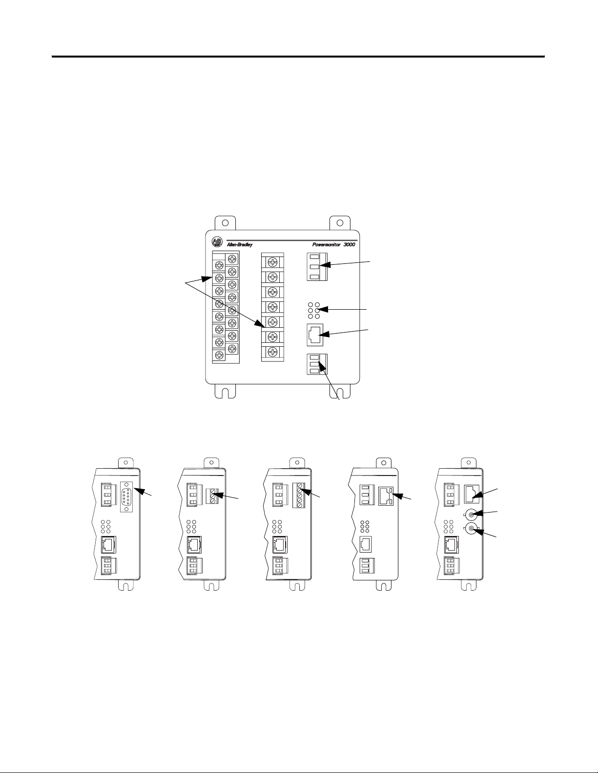
The master module contains the main microprocessor-based
monitoring functions, including terminations for power system
connections, status inputs, control outputs, a native RS-485
communication port, and a port for the display module.
Configuration
Although the power monitor ships from the factory with default
settings, you need to configure it for your particular requirements.
You may configure the power monitor by using the optional display
module. Alternately, you may use an external device or application to
write configuration, operational parameters, and commands to the
master module through its native or optional communication port.
Optional external applications that you may use for power monitor
configuration include RSPower, RSPowerPlus, and RSEnergyMetrix
software operating on a computer with a Microsoft Windows
operating system.
Contact your local Rockwell Automation sales office or distributor, or
visit http://www.software.rockwell.com/
available software packages.
for more information on
Communication
Every power monitor comes with a native RS-485 communication port
that supports the Allen-Bradley DF1 half- or full-duplex slave and
Modbus RTU slave protocols. The native port is suitable for
communicating to devices including the following:
• PLC-5, SLC 500, and ControlLogix processors
• RSLinx software with DDE/OPC server functionality
• Modbus RTU masters
• Other third-party devices
• Software that you develop
You may also specify power monitors with optional communication
ports including the following:
• Serial RS-232 (DF1 half- or full-duplex or Modbus RTU slave)
• Remote I/O
• DeviceNet
• EtherNet/IP (CIP and/or CSP, Modbus TCP)
• ControlNet
14 Publication 1404-UM001F-EN-P - November 2009
Page 15

Product Description Chapter 2
You may integrate a power monitor into a programmable controller
based control and monitoring system by using your choice of the
native or optional communication methods.
Display Module
The Bulletin 1404 display module is an optional user interface device.
The display module provides the most economical and simplest
method for setting up and configuring the master module for
operation.
The display module has a highly visible, two-line LED display and
four operator buttons with tactile feedback. Use the buttons and
display to navigate through a series of menus for configuration,
commands, and data display.
The display module is shipped with a 3 m (10 ft) long, shielded
four-pair cable that provides power and serial communication
between the master module and the display module. The display
module fits into a standard ANSI 4 in. analog meter cutout for panel
mounting. Only one display module may connect to a master module,
although you may use one display module to configure and monitor
any number of master modules one at a time.
Publication 1404-UM001F-EN-P - November 2009 15
Page 16

Chapter 2 Product Description
Performance Features
The power monitor is available in four basic models, designated M4,
M5, M6, and M8. Each model offers specific functionality as indicated
in this table. The M5 model offers M4 functionality and can be
field-upgraded to an M6 or M8 model for an additional charge.
Product Features of Powermonitor 3000 Module
M4 M5 M6 M8 Master Module Features
••••Voltage, current, power measurements and display
••••Compatible with PLC-5, SLC 500, and ControlLogix controllers
••••Compatible with RSLinx, RSPower, RSPowerPlus,
RSEnergyMetrix, and RSView32 software
••••Output control via control relays or PLC controllers
••••Demo mode for training
••••10 user configurable setpoints
••••Discrete condition monitoring via status inputs
••••Electronic KYZ pulse output
••••Form C ANSI C37.90-1989 rated relay for direct breaker tripping
••••Time stamped data logging of system measurements and events
••••Configurable trend log, up to 45,000 records deep
••••Event log 50 records deep
••••Firmware upgrades without removing module
••••Total harmonic distortion (THD) and Crest Factor
••••Automatic network-based time synchronization via SNTP
••••Daylight Saving Time
•••
•••
ANSI C12.20 Class 0.5 revenue metering accuracy
EN60687 Class 0.5 revenue metering accuracy
•••Canadian Revenue Meter specification accuracy
•• Field upgradeable to M6 or M8 (extra cost option)
••10 additional setpoints with more options
••Event Log an additional 50 records deep
••User configurable oscillography up to 400 cycles @ 60 Hz
••TIF, K-factor and IEEE-519 Pass/Fail
••Sag and swell detection with oscillogram capture
••Load factor log 12 records (months) deep
••Calculates amplitude and % distortion for harmonics 1…41
• Calculates amplitude and % distortion for harmonics 1…63
• Sub-cycle transient capture and metering
• Transducer and Energy Meter modes with improved update rate
(1)
Class 0.2 revenue metering accuracy available as an extra-cost option.
(1)
(1)
16 Publication 1404-UM001F-EN-P - November 2009
Page 17

Product Description Chapter 2
Communication Options
In addition to the native RS-485 communication port, several
factory-installed communication options are also available. These
options make it possible for a user to select Powermonitor 3000 units
to provide power and energy information into a variety of existing or
new control systems and communication networks. Each
communication option supports bi-directional data transfer with
external devices or applications. Metering measurement, logging,
configuration and status data may be accessed via communication.
Communication options are set in the master module. You may
configure communication by using the display module or via
communication to an external application such as RSPower,
RSPowerPlus, or RSEnergyMetrix. Refer to the information later in this
manual on configuration and operation of the communication options.
Refer to the Powermonitor 3000 Installation Manual, publication
1404-IN007
selected communication options.
The last 3 characters of the catalog number specify the communication
option of the Powermonitor 3000 unit.
, for installation and wiring information related to your
RS-485 Native Communication
A catalog number ending in -000 specifies a power monitor equipped
with only a native RS-485 communication port with the following
performance features:
• Communication rates 1200, 2400, 4800, 9600, 19,200, 38,400, and
57,600 Kbps
• RS-485 cable length 1219 m (4000 ft)
• Cable type: two-wire shielded (Belden 9841)
• Multi-drop capabilities up to 32 nodes (half-duplex only)
• Update rate: 100 ms minimum
• Read/Write data table access to all data
• One user-configurable data table
• Supports DF1 half-duplex, DF1 full-duplex, and Modbus RTU
communication protocol
• Used for field firmware upgrades
The serial communication port operates as a responder on a
full-duplex point-to-point link. You must verify that no more
than one message is triggered simultaneously.
Publication 1404-UM001F-EN-P - November 2009 17
Page 18

Chapter 2 Product Description
RS-232 Optional Communication
A catalog number ending in -232 specifies a power monitor with one
RS-232 communication port in addition to the native RS-485
communication port. You select which of the two ports is active, as
the two ports may not be used concurrently. The RS-232 port supports
the same performance features as the RS-485 port, with the following
exceptions:
• RS-232 cable length 15.24 m (50 ft) maximum
• Cable type: three-wire shielded (Belden 9608)
• Point-to-point wiring
• The RS-232 port operates as a responder. Unlike the RS-485 port,
the RS-232 port supports overlapping messages.
Remote I/O Optional Communication
A catalog number ending in -RIO specifies a power monitor with a
remote I/O communication port in addition to the native RS-485
communication port. The remote I/O option permits concurrent use
of both communication ports. The remote I/O port has the following
performance features:
• One-quarter rack slave device
• Three communication rate settings: 57.6, 115.2, and 230.4 Kbps
• Cable lengths up to 3048 m (10,000 ft)
• Node capacity up to 32 nodes
• Update rates for discrete I/O: 5 ms
• Update rates for block transfers: 50 ms minimum
• Two discrete inputs
• Eleven discrete outputs
• Read/Write block transfer data tables for access to all data
18 Publication 1404-UM001F-EN-P - November 2009
Page 19

Product Description Chapter 2
DeviceNet Optional Communication
A catalog number ending in -DNT specifies a power monitor with a
DeviceNet port in addition to the native RS-485 port. The DeviceNet
option permits concurrent use of both communication ports. The
DeviceNet port has the following performance features:
• Adapter class device
• Four communication rate settings: 125, 250, 500 Kbps, and
AutoBaud
• Remotely settable communication rate
• Cable length up to 500 m (1640 ft) maximum
• Node capacity up to 64 nodes including master
• Remotely settable node address
• Shielded twisted-pair media containing both signal and power
conductors
• Update rates for I/O channel: 100 ms minimum
• Update rates for explicit messaging: 250 ms minimum
• Configurable I/O channel assembly instance: six parameters
default, twenty-three maximum
• Configurable explicit assembly instance: seventeen parameters
default, twenty-three parameters maximum
• Explicit assembly instances for access to all data
• Twenty-three single-instance parameters
• Two I/O assembly instances
• May be reset remotely through Identity Object
• Support for up to four concurrent clients
• Supports DeviceNet heartbeat facility
Ethernet Optional Communication
A catalog number ending in -ENT specifies a power monitor with one
active 10/100BaseT Ethernet communication port in addition to the
native RS-485 port. The Ethernet port has the following performance
features:
• Connect to PLC-5E, SLC 5/05, ControlLogix Ethernet Bridge
controllers, and the 1761-NET-ENI module products
• Built-in Internet Web page support
• Compatible with RSPower, RSPowerPlus, RSEnergyMetrix, and
RSView32 software
• Ethernet communication rate: 10/100 Mbps
Publication 1404-UM001F-EN-P - November 2009 19
Page 20

Chapter 2 Product Description
• Compatible with commercially available network bridges,
routers, hubs and switches
• Fully software configurable
• Supports RSLinx software
• Supports Allen-Bradley Client Server Protocol (CSP)
• Supports EtherNet/IP (CIP) protocol
• Configurable I/O channel assembly instance: six parameters
default, twenty-three maximum
• Configurable explicit assembly instance: seventeen parameters
default, twenty-three parameters maximum
• Explicit assembly instances for access to all data
• Two I/O assembly instances
• Remotely resettable through Identity Object
• Supports up to 64 CIP/HTTP concurrent connections
• Data read latency: less than 10 ms
• Update rates for real-time metering data: 100 ms minimum
• Update rates for logged data: 250 ms minimum
• Supports network-based time synchronization via SNTP
• Supports networked demand period synchronization
• Supports Class 1 scheduled connection for I/O data
ControlNet Optional Communication
A catalog number ending in -CNT specifies a power monitor with a
ControlNet communication interface in addition to the native RS-485
port. The ControlNet interface has the following features:
• Adapter class device
• Supports redundant media or single media applications; physical
connections include NAP port and two BNC connectors
• ControlNet International conformace tested and approved
• Compatible with ControlLogix, PLC-5, and SLC controllers,
PanelView units, RSEnergyMetrix, RSPower, and RSPowerPlus
software, and more
• All power monitor data readable/writable via unscheduled
(UCMM or Class 3) connection to Powermonitor assembly object
instances 3…64
• Supports scheduled messaging (Class 1 connection); one
assembly instance of configurable content from the power
monitor and one assembly instance of fixed content to the
power monitor
20 Publication 1404-UM001F-EN-P - November 2009
Page 21
Powermonitor 3000Powermonitor 3000Powermonitor 3000
Powermonitor 3000
Powermonitor 3000
Terminal Blocks
Product Description Chapter 2
• Supports up to 64 concurrent Class 1 connections to instance 1
and one Class 1 connection to Instance 2.
• ControlFlash can be used to update ControlNet communication
firmware
• Supports ControlLogix message types: CIP Generic, PLC-5 Typed
• Set power monitor node address (MAC ID) via display module,
native comm port, or ControlNet assembly instance 12
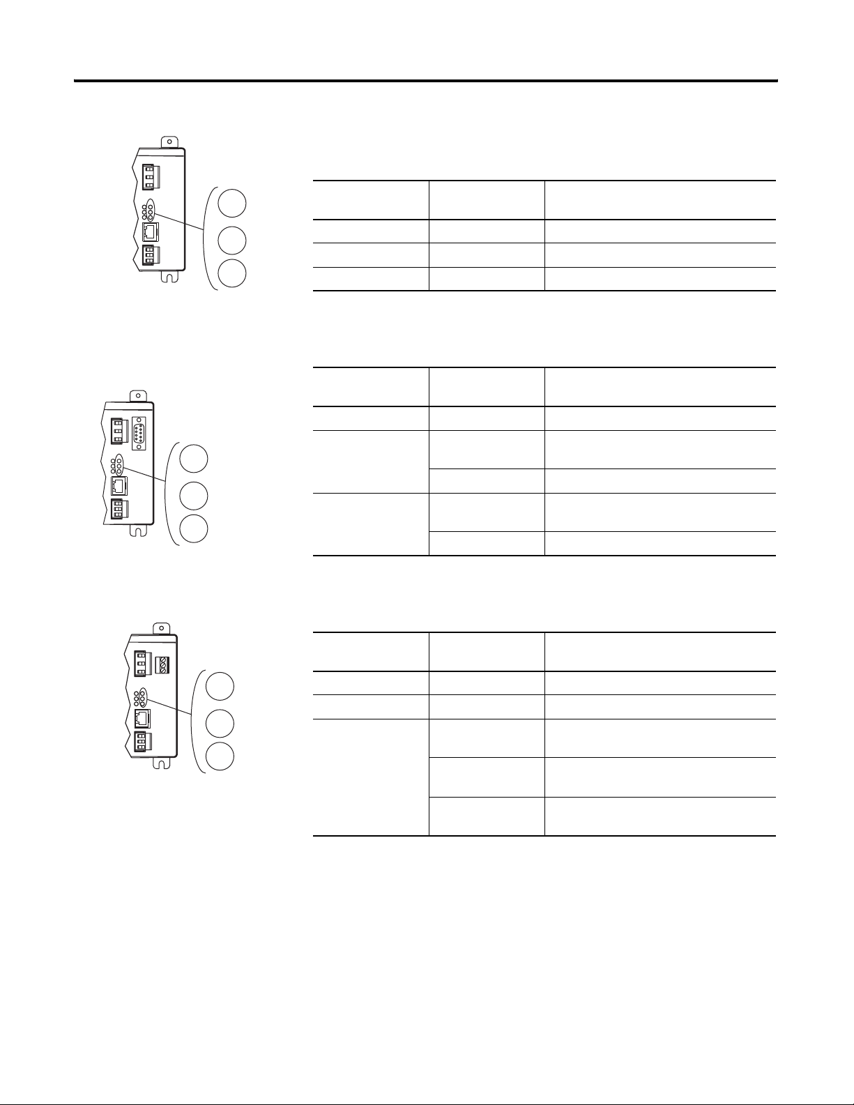
Master Module with Various Communication Options
Removable Status Input
Connector
Status Indicators
Display Module Port
Optional
RS-232 Port
RS-485 (Native)
Communication Port
Optional
NAP Port
Optional
Remote I/O
Port
Optional
DeviceNet
Port
Optional
Ethernet
10BaseT
Port
Optional
ControlNet
Channel A
Optional
ControlNet
Channel B
Publication 1404-UM001F-EN-P - November 2009 21
Page 22
Chapter 2 Product Description
Powermonitor 3000
RX
TX
RS-485
Status Indicators
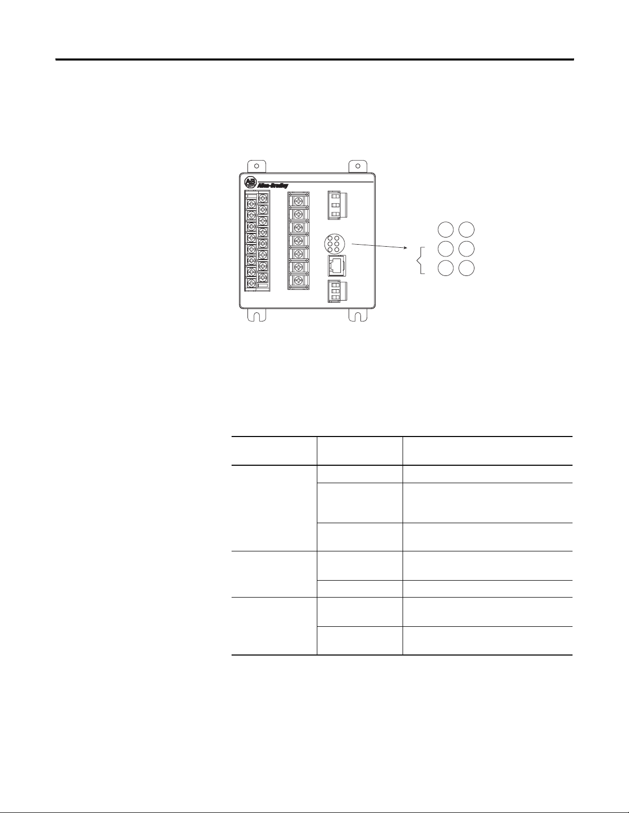
The power monitor is equipped with six, two-color status indicators
arranged as shown. Functions of the indicators differ among the
various communication configurations.
Status Indicators
MODULE
STATUS
The three indicators on the left, display the same information on
Powermonitor 3000 units with any communication option including
native RS-485 communication only. The three indicators on the right
have different labels and different indications depending on the
communication option selected, as shown in this table.
Status Indicators All Powermonitor 3000 Models
Status Indicator Indicator Color Indicator State and Communication
Condition
Module Status Off Control power is off or insufficient
Steady Red Major fault; internal self-test has failed. If a
power cycle does not correct the problem,
call customer support
Steady Green Powermonitor 3000 unit is operating
normally
RS-485 RX Off The RS-485 bus is idle; no active data is
present
Flashing Green Active data is present on the RS-485 bus
RS-485 TX Off Powermonitor 3000 unit is not transmitting
data onto the RS-485 bus
Flashing Green Powermonitor 3000 unit is transmitting
data onto the RS-485 bus
22 Publication 1404-UM001F-EN-P - November 2009
Page 23
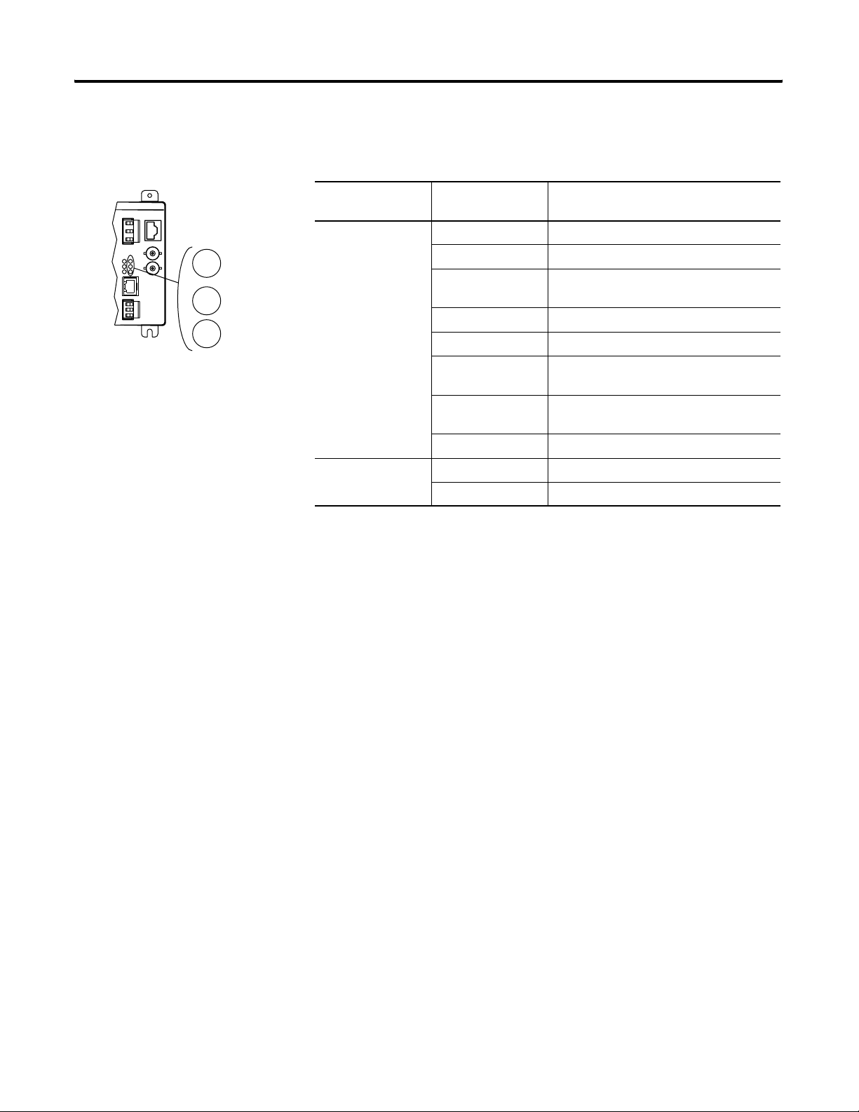
Product Description Chapter 2
Powermonitor 3000
Powermonitor 3000
Powermonitor 3000
Native RS-485 Communication Only (catalog numbers ending in -000)
F1
RX
TX
}
F1
F2
F3
RS-232
Status Indicator Indicator Color Indicator State and Communication
Condition
F1 Off Not Used
F2 Off Not Used
F3 Off Not Used
RS-232 Optional Communication (catalog numbers ending in -232)
Status Indicator Indicator Color Indicator State and Communication
Condition
F1 Off Not Used
RS-232 RX Off The RS-232 bus is idle; no active data is
present
Flashing Green Power monitor is receiving data.
RS-232 TX Off The power monitor is not transmitting any
data onto the RS-232 bus
Flashing Green The power monitor is transmitting data.
F1
F2
R I/O
Remote I/O Optional Communication (catalog numbers ending in -RIO)
Status Indicator Indicator Color Indicator State and Communication
Condition
F1 Off Not Used
F2 Off Not Used
R I/O Off Remote I/O communication has not been
established
Flashing Green Remote I/O communication has been
established but there are errors
Steady Green Remote I/O communication has been
established
Publication 1404-UM001F-EN-P - November 2009 23
Page 24
Chapter 2 Product Description
Powermonitor 3000
Powermonitor 3000
F1
F2
NETWORK
STATUS
DeviceNet Optional Communication (catalog numbers ending in -DNT)
Status Indicator Indicator Color Indicator State and Communication
Condition
F1 Off Not Used
F2 Off Not Used
Network Status Off Power is off or the power monitor is not
online
Flashing Green Network status is OK, no connections
established
Steady Green Network status is OK, connections
established
Flashing Red Recoverable communication failure; port is
restarting
Steady Red Non-recoverable communication error;
check wiring and configuration parameters
LNK
ACT
F1
F2
NETWORK
STATUS
EtherNet/IP Optional Communication (catalog numbers ending in -ENT)
Status Indicator Indicator Color Indicator State and Communication
Condition
LNK Off No valid physical Ethernet connection
Steady Green Valid physical Ethernet connection
ACT Strobing or
Solid Yellow
F1 Off Not Used
F2 Off Not Used
NETWORK STATUS Off No power
Flashing Green No established connections
Steady Green Connected; has at least one established
Flashing Red Connection timeout; one or more
Steady Red Duplicate IP; the IP address assigned to this
Flashing Green/Red Selftest; this device is performing a
Power monitor transmitting onto Ethernet
connection
connections to this device has timed-out
device is already in use
power-up self test
24 Publication 1404-UM001F-EN-P - November 2009
Page 25
Product Description Chapter 2
Powermonitor 3000
ControlNet Optional Communication (catalog numbers ending in -CNT)
Status Indicator Indicator Color Indicator State and Communication
Condition
CHAN A
CHAN B
STATUS
CHAN A and
CHAN B
Off No power or Channel disabled
Steady Red Faulted unit
Alternating
Self-test
red/green
Alternating red/off Incorrect node configuration
Steady green Normal operation
Flashing green/off Temporary errors or node is not configured
to go online
Flashing red/off Media fault or no other nodes present on
network
Flashing red/green Incorrect network configuration
Status Steady Green Normal operation
Flashing green/red Communication card power-up self-test
Publication 1404-UM001F-EN-P - November 2009 25
Page 26

Chapter 2 Product Description
26 Publication 1404-UM001F-EN-P - November 2009
Page 27

Chapter
3
Powermonitor 3000 Unit Operations
The Powermonitor 3000 unit is a microprocessor-based electrical
power- and energy-measuring device. It connects to your three-phase
or single-phase ac power system directly or through instrument
transformers (PTs and CTs). It converts instantaneous voltage and
current values to digital values, and uses the resulting digital values in
calculations of things such as voltage, current, power, and energy. You
may access the resulting metering values manually by using the
display module or automatically by using communication with an
external device or application.
The basic operations of the Powermonitor 3000 unit include the
following:
Metering Functionality
• Metering functionality
• Operational and status indication
• Operation of the display module
• Display module menus and parameter structure
• Setup and configuration by using the display module
• Data monitoring by using the display module
• Issuing commands by using the display module
Other power monitor features such as communication, setpoint
operations, I/O operations, data logging, oscillography, harmonics,
sag/swell detection, load factor calculation, and transient detection are
covered later in this manual.
The power monitor performs calculations on scaled, digital voltage
and current values. Signals connected to the voltage and current
inputs are sampled and their instantaneous values are converted to
digital values in an analog-to-digital (A/D) converter section. These
values are scaled according to configured PT Primary, PT Secondary,
CT Primary, and CT Secondary parameters, and evaluated according
to the configured Wiring Mode parameter. Metering results are
available for display on the display module, in the communication
data tables, and for use in setpoint programming and data logging.
The table on page 28
in each Powermonitor 3000 unit, and notes which measurements you
may view by using the display module.
27Publication 1404-UM001F-EN-P - November 2009 27
provides a summary of measurements produced
Page 28

Chapter 3 Powermonitor 3000 Unit Operations
Summary of Measurements
M4 M5M6 M8
DM
(1)
Measurement
•••• Current, per phase and neutral
•••• Average current
•••• Positive sequence current
•••• Negative sequence current
•••• Percent current unbalance
•••• Voltage per phase L-L, and L-N on four-wire systems
•••• Average voltage per phase L-L, and L-N on four-wire systems
•••• Positive sequence voltage
•••• Negative sequence voltage
•••• Percent voltage unbalance
•••• Frequency
•••• Phase rotation (ABC, ACB)
•••• Real power (watts), total and per phase on four-wire systems
•••• Reactive power (VARs), total and per phase on four-wire
systems
•••• Apparent power (VA), total and per phase on four-wire systems
•••• True power factor (PF), total and per phase on four-wire
systems
•••• Displacement PF, total and per phase on four-wire systems
•••• Distortion PF, total and per phase on four-wire systems
•••• Energy consumption in kilowatt-hours (kWh), forward, reverse,
and net
•••• Reactive energy consumption in kVAR-hours, forward, reverse,
and net
•••• Apparent energy consumption in kVA-hours
•••• Current consumption in ampere-hours
•••• Demand (kA, kW, kVAR, and kVA)
•••• Projected demand (kA, kW, kVAR, and kVA)
••• Load factor calculation (amps, watts, VAR, and VA)
•••• IEEE percent THD (total harmonic distortion)
•••• IEC percent THD (Distortion Index) (DIN)
•••• Crest Factor
••• TIF (Telephone Interference Factor)
••• K-factor
••• IEEE 519 TDD (total demand distortion)
••• IEEE 519 pass/fail calculation on voltage and current
•• Individual percent and RMS magnitude, harmonics 1…41
• Individual percent and RMS magnitude, harmonics 42…63
•• Oscillography capture data
• Transient voltage and current index
• RMS voltage and current per phase for each cycle of transient
capture
• Transient capture wave form data
(1)
If this box is checked, you may view the measurement by using display module. If not, you may access
measurements by using communication only.
28 Publication 1404-UM001F-EN-P - November 2009
Page 29

Powermonitor 3000 Unit Operations Chapter 3
Metering Accuracy Class
In the Selftest/Diagnostic Results table, element 26 is a read-only
parameter that indicates the revenue metering accuracy class of the
master module. If this element contains the value 0, the master
module meets ANSI C12.16 and EN61036 Class 1 requirements for
accuracy. If this element contains the value 1, the master module
meets ANSI C12.20 Class 0.5, EN60687 Class 0.5, and Canadian
standard CAN3-C17-M84 requirements for accuracy. If this element
contains the value 2, the master module meets ANSI C12.20 Class 0.2,
EN60687 Class 0.2, and Canadian standard CAN3-C17-M84
requirements for accuracy. The revenue metering accuracy class is
also indicated on the side of the master module and can be accessed
via the display module
(DISPLAY > STATUS > ACCURACY CLASS).
Metering Accuracy Class
Model Class 1 Class 0.5 Class 0.2
M4 Standard Not Available Not Available
M5 Standard Optional
M6 Standard Optional
M8 Standard Optional
Expressing Metered Data on the Display Module
The display module displays scaled metered data in its basic units,
such as volts, amps, watts. Prefixes such as K or M are used to denote
multipliers of 1,000 (kilo-) and 1,000,000 (mega-). The display module
expresses power factor as a percentage, with a positive value
indicating leading and a negative value indicating lagging.
The display module displays values to a maximum precision of five
significant digits.
Viewing Metered Data by Using the Display Module
The display module makes it easy to view the metering data produced
by the power monitor.
Refer to display module functionality later in this chapter for
information on use of the display module.
Publication 1404-UM001F-EN-P - November 2009 29
Page 30

Chapter 3 Powermonitor 3000 Unit Operations
Voltage, Current, and Frequency Results
Line-to-line voltage results (L1-L2, L2-L3, and L3-L1) are calculated for
all wiring modes. Line-to-neutral voltage results (L1-N, L2-N, and
L3-N) are calculated in wye and single-phase wiring modes only. In
delta wiring modes, line-to-neutral voltages return a zero value.
Average line-to-line (Avg. L-L) and line-to-neutral (Avg. L-N) voltage
results return the mathematical average of the three line-to-line or
line-to-neutral voltages, respectively. For single-phase wiring modes,
the average line-to-neutral voltage is the mathematical average of
phase 1 to neutral (L1-N) and phase 2 to neutral (L2-N) voltages.
Voltage results return 999 if the line-to-neutral voltage exceeds
347 volts.
Current results include individual phase current (L1, L2, L3) and
average three-phase current. L4 current returns neutral or
zero-sequence current (refer to symmetrical component analysis
discussion below).
Frequency results include Last cycle frequency and Average
Frequency, calculated over your selection of either one or the last
eight cycles. Frequency results return 0 if either the frequency is less
than 40 Hz or if the voltage magnitude on all three voltage inputs is
too low. Frequency results return 999 if the frequency is greater than
75 Hz. The power monitor selects one voltage phase input for
frequency calculations and automatically switches to another in case
of a phase loss. Frequency source indicates which phase is used to
calculate frequency results.
Frequency source is accessible only via communication.
Phase rotation returns a value indicating forward (ABC), reverse
(ACB) or no rotation.
RMS Resolution and Averaging
There are a number of configuration options in the power monitor
that affect metering results.
• RMS Resolution – the high-resolution setting provides more
accurate RMS results when significant levels of harmonics are
present. You may also configure for nominal resolution if you
require faster update rates but can accept lower accuracy as a
trade-off. The M4 default is Nominal. The M5/M6/M8 default is
High.
• RMS Result Averaging – the default setting provides a more
steady result by averaging the results of the last eight
calculations. You may also configure no averaging for the fastest
response to a changing signal.
30 Publication 1404-UM001F-EN-P - November 2009
Page 31

Powermonitor 3000 Unit Operations Chapter 3
• Frequency Averaging – like the RMS result averaging, the default
setting provides for a smoother response by averaging the
frequency of each of the last eight cycles. You may select no
averaging to return the frequency of only the last cycle
Refer to
Advanced Device Configuration on page 50 for more
information.
Symmetrical Component Analysis Results
The power monitor calculates sequence voltages and currents for use
in symmetrical component analysis, a method of mathematically
transforming a set of unbalanced three-phase vectors into three sets of
balanced vectors. The positive sequence components are a set of
vectors that rotate the same direction as the original power vectors,
and represent that portion of the applied voltage or current capable of
doing work. Negative sequence components rotate opposite to the
original vectors, and represent the portion of the applied power that
results in losses due to unbalance. The percent Unbalance value is the
ratio between the negative and positive current sequence in a
three-phase system and is the most accurate measurement of current
unbalance because it takes into account the magnitude of the
individual currents and the relative phase displacement. The zero
sequence component is a single vector that does not rotate, and
represents ground or neutral current or voltage. The component
analysis results returned include the following:
• Positive Sequence Current
• Negative Sequence Current
• % Current Unbalance
• Positive Sequence Voltage
• Negative Sequence Voltage
• % Voltage Unbalance
• L4 current, which is the zero-sequence current on a wye system
when neutral current is connected to the I4 current input or in
delta systems when an external zero sequence transformer is
connected to the I4 input
The Voltage, Current, and Frequency Metering table on page 32
summarizes the voltage and current metering information provided by
the power monitor.
Publication 1404-UM001F-EN-P - November 2009 31
Page 32

Chapter 3 Powermonitor 3000 Unit Operations
Voltage, Current, and Frequency Metering
Parameter Description Range Units
Phase 1 L-N Voltage RMS line to neutral voltage of individual phase or three-phase
Phase 2 L-N Voltage
average
0…999.9x10
22
Volts
Phase 3 L-N Voltage
3-Phase Average L-N Voltage
Phase 1 L-L Voltage RMS line to line voltage of individual phase or three-phase
Phase 2 L-L Voltage
average
0…999.9x10
22
Volts
Phase 3 L-L Voltage
3-Phase L-L Voltage
Phase 1 Current RMS line current in individual phase or three-phase average
0…999.9x10
22
Amps
Phase 2 Current
Phase 3 Current
3-Phase Average Current
Phase 4 (Neutral) Current RMS current of phase 4, also known as neutral or zero-sequence
0…999.9x10
22
Amps
current
Frequency The frequency of the voltage 40.0…75.0 Hertz
Phase Rotation The phase rotation of a three-phase system None
N/A
ABC
ACB
Voltage Positive Sequence Magnitude of positive sequence voltage in a three-phase
(1)
system
Voltage Negative Sequence Magnitude of negative sequence voltage in a three-phase
(1)
system
Current Positive Sequence Magnitude of positive sequence current in a three-phase system
Current Negative Sequence Magnitude of negative sequence current in a three-phase system
Voltage Unbalance The ratio between the negative and positive voltage sequence in
0…999.9x10²²
0…999.9x10²²
0…999.9x10
0…999.9x10
0…100 Percent
Volts
Volts
22
Amps
22
Amps
a three-phase system
Current Unbalance The ratio between the negative and positive current sequence in
0…100 Percent
a three-phase system
(1)
Expressed in line-to-neutral volts for Wye and line-to-line volts for Delta wiring modes.
Power Results
Real power, that is the portion of the voltage and current applied to a
power system that is doing work, is calculated on a per-phase (L1 Real
Power, L2 Real Power, L3 Real Power), and Total Real Power. L1
Reactive Power, L2 Reactive Power, L3 Reactive Power and Total
Reactive Power similarly return that portion of the power used in
capacitive or inductive reactance in the power system and doing no
work. L1 Apparent Power, L2 Apparent Power, L3 Apparent Power
and Total Apparent Power return the apparent power, which is the
simple mathematical product of the system voltage and system
current.
For single-phase wiring mode, all L3 power values remain at zero and
are not included in the total power calculation.
32 Publication 1404-UM001F-EN-P - November 2009
Page 33

Powermonitor 3000 Unit Operations Chapter 3
Power Factor Results
The power monitor calculates true, displacement and distortion power
factor, each on a per-phase and total three-phase basis. True power
factor is the ratio between the total true power and total apparent
power (in percent), and takes into account the effect of phase shift
between the voltage and current as well as any harmonics present.
Displacement power factor is the cosine of the difference between the
phase angle of the fundamental voltage and current (in percent), and
reflects the value a typical analog power factor meter would measure.
The true power factor and displacement power factor are equal only if
there are no harmonics present in either the voltage or current. These
values are signed to show lead (+) or lag (-). Distortion power factor
is the ratio between the magnitude of the fundamental and the sum of
the magnitudes for all of the current harmonics (in percent).
The power quantities (kW, kWh, kVAR, kVARh, and power factor) are
four-quadrant measurements. The power monitor measures and
expresses these measurements in a way that allows you to determine
the magnitude and direction of both the real power flow and the
reactive power flow.
Explanation of Power Factor Values on page 34
indicates the
relationship between these quantities and the numeric signs used by
the power monitor to convey the information.
Power and Power Factor Results
Parameter Description Range Units
Phase 1 Power Power of individual phase or sum of phases;
Phase 2 Power
Phase 3 Power
3-Phase Total Power
Phase 1 Reactive Power Reactive power of individual phase or sum of all
Phase 2 Reactive Power
Phase 3 Reactive Power
3-Phase Total Reactive Power
Phase 1 Apparent Power Apparent power of individual phase or sum of all
Phase 2 Apparent Power
Phase 3 Apparent Power
3-Phase Total Apparent Power
signed to show direction.
phases; signed to show direction.
phases.
0…999.9x10
0…999.9x10
0…999.9x10
22
22
22
Watts
VARs
(volt-amperes
reactive)
VA
(volt-amperes)
Publication 1404-UM001F-EN-P - November 2009 33
Page 34

Chapter 3 Powermonitor 3000 Unit Operations
Power and Power Factor Results
Parameter Description Range Units
Phase 1 True Power Factor The ratio between the power and apparent
Phase 2 True Power Factor
power for an individual phase or all three
phases; signed to show lead (+) or lag (-).
-100…100 Percent
Phase 3 True Power Factor
Total True Power Factor
Phase 1 Distortion Power Factor The ratio between the magnitude of the
Phase 2 Distortion Power Factor
Phase 3 Distortion Power Factor
fundamental and the sum of the magnitudes for
all of the current harmonics for an individual
phase or all three phases.
Total Distortion Power Factor
Phase 1 Displacement Power Factor The cosine of the phase angle between the
Phase 2 Displacement Power Factor
Phase 3 Displacement Power Factor
fundamental voltage and current for an
individual phase or all three phases; signed to
show lead (+) or lag (-).
Total Displacement Power Factor
Explanation of Power Factor Values
Pf = 0
+kVAR (Import)
kVARHR-F (Forward)
(Power Factor
Leading)
(+)
Pf = 100%
-kW (Export)
kWH-R (Reverse)
180˚
(Power Factor
Lagging)
(-)
Pf = 0
-kVAR (Export)
kVARHR-R (Reverse)
0…100 Percent
-100…100 Percent
90˚
(Power Factor
Lagging)
(-)
I
II
IV
III
(Power Factor
Leading)
(+)
270˚
Pf = 100%
0˚
+kW (Import)
kWH-F (Forward)
Energy Results
The power monitor calculates energy values including kWh forward,
reverse and net; kVAh; kVARh forward, reverse and net; and kAh. You
may read these values by using the display module or via
communication.
34 Publication 1404-UM001F-EN-P - November 2009
Page 35

Powermonitor 3000 Unit Operations Chapter 3
Configurable Energy Counter Rollover
You may configure the number of digits at which energy values roll
over to zero. The parameter range is 4
Configure this setting in Advanced Device Configuration by using the
display module or by writing to the Advanced Device Configuration
table on page 196
This setting lets you optimize the energy counter rollover for use with
applications that support a limited number of significant digits. For
instance, the display module supports a resolution of five significant
digits. The Trend Log, which is used for automatic data re-population
in some energy logging applications such as RSEnergyMetrix, supports
twelve significant digits with eight digits of precision.
.
…15 digits.
Demand Calculation
A typical industrial utility bill includes not only an energy (or kWh)
charge but also a Demand charge. Demand is equal to the average
power level during a predefined time interval. Some power providers
may base demand on current, VA, or VARs instead of kW. This interval
continuously repeats and is typically between five and 30 minutes in
length. The formula for kW demand is shown below.
tT+
1
Demand
T = Demand interval duration
t = Time at beginning of interval
P(t) = Power as a function of time
Usually, a utility rate tariff includes a peak demand charge,
determined by the peak demand that occurs during a specified period,
which may be one month, one year, or some other duration. As a
result, only one occurrence of a high demand level can have a
long-term effect on your utility bill. The peak demand value indicates
to the utility the reserve capacity they need to satisfy your short-term
power requirements. The peak demand charge helps to pay the utility
for maintaining this instantaneous capacity.
---
T
Pt()td
•=
∫
t
The power monitor computes demand levels for watts, VA, amps, and
VARs, and provides three different methods for projecting demand.
Publication 1404-UM001F-EN-P - November 2009 35
Page 36

Chapter 3 Powermonitor 3000 Unit Operations
The utility may provide a pulse that indicates the end of each demand
interval. The utility updates the demand value at the end of each
interval and maintains the highest value obtained during any interval.
This method is known as thermal demand. You may set up a power
monitor to determine its demand interval from the utility pulse. To
accomplish this, connect the utility pulse to status input #2 and make
the appropriate settings in the Advanced Device Configuration.
If the utility does not provide a demand interval pulse, you won’t be
able to synchronize with the utility to control your demand. In this
case, you may use the sliding window method. This method breaks
the demand interval into many sub-intervals and updates the demand
value at the end of each sub-interval. For example a five-minute
interval might be divided into five one-minute sub-intervals. The
demand for each one-minute interval is calculated and at the end of
five minutes the average value of the sub-intervals is computed to
obtain a demand value. At the end of the sixth minute, the value for
sub-interval one is discarded and a new demand value computed
based on sub-intervals two through six. In this way a new five-minute
demand value is obtained every minute. The maximum value is then
maintained as the peak demand. This method approximates the actual
demand the utility measures.
How can you minimize your peak demand in order to reduce your
utility demand penalty charges? One way is to measure the power
being used and project the demand level at the end of the interval.
This method permits you to reduce power consumption when the
projected demand reaches a predetermined threshold, thus preventing
the final demand from exceeding the desired level.
Projected Demand Calculation
Select the best projection method for your system by comparing the
projected values from each method with the actual demand at the end
of the interval. The three methods of projecting demand are described
below.
36 Publication 1404-UM001F-EN-P - November 2009
Page 37

Powermonitor 3000 Unit Operations Chapter 3
Instantaneous
The power monitor computes instantaneous demand by substituting
the elapsed interval duration for the total interval duration (T) in the
demand equation. It is therefore identical to the standard computation
except it integrates the power only over the elapsed interval duration
and calculates the average value over the elapsed duration. The
modified equation thus becomes.
t2
1
Demand
(t2 - t1) = Elapsed interval duration and is less than T
----------------
t2 t1–
Pt()td
•=
∫
t1
First Order Projection
The first order demand projection does the following:
• Utilizes the instantaneous demand as a starting point
• Computes the trend of the instantaneous demand
• Computes the time remaining in the interval
• Performs a first order projection of what the final demand is at
the end of the interval.
This method may be useful where your system has a significant base
load with additional loads that are switched in and out during the
interval.
Second Order Projection
The second order demand projection begins with the first order
projection, then it does the following:
• Computes the rate of change of the first order trend
• Computes the time remaining in the interval
• Performs a second order projection of what the final demand is
at the end of the interval
This method may be useful where your power system has little or no
base load and a load profile that increases over the duration of the
interval. A second order projection is more sensitive to rapid load
changes than the other methods.
Publication 1404-UM001F-EN-P - November 2009 37
Page 38

Chapter 3 Powermonitor 3000 Unit Operations
Energy and Demand Results
Parameter Description Range Units
Kilo-Watt Hours Forward The total real power consumed
0…1.0x10
12
kWh
Kilo-Watt Hours Reverse The total real power produced
Kilo-Watt Hours Net The sum of forward and reverse power
Kilo-VAR Hours Forward The total reactive power consumed
0…1.0x10
12
kVARh
Kilo-VAR Hours Reverse The total reactive power produced
Kilo-VAR Hours Net The sum of forward and reverse reactive power
Kilo-VA Hours Net The total apparent power consumed
Amp Hours Net Accumulated amp-hours consumed
Demand Current The calculated demand for average current
0…1.0x10
0…1.0x10
0…999.9x10
12
12
21
kVAh
Ah
Amps
Max Demand Current The maximum (peak) demand for current. (included in
Min/Max Log)
Demand Kilo-Watts The calculated demand for real power
0…999.9x10
21
kW
Max Demand Kilo-Watts The maximum (peak) demand for real power
(included in Min/Max Log)
Demand Kilo-VARs The calculated demand for reactive power
0…999.9x10
21
kVAR
Max Demand Kilo-VARs The maximum (peak) demand for reactive power
(included in Min/Max Log)
Demand Kilo-VA The calculated demand for apparent power
0…999.9x10
21
kVA
Max Demand Kilo-VA The maximum (peak) demand for apparent power
(included in Min/Max Log)
Projected Current Demand
Projected Kilo-Watt Demand
Projected Kilo-VAR Demand
Projected Kilo-VA Demand
(1)
Values returned depend on user selection of projected demand type in Advanced Configuration.
(1)
(1)
(1)
(1)
The projected demand for average current
The projected demand for real power
The projected demand for reactive power
The projected demand for apparent power
0…999.9x10
0…999.9x10
0…999.9x10
0…999.9x10
21
21
21
21
Amps
kW
kVARs
kVA
Display Module
The display module is a simple terminal that allows you to easily view
metering parameters or change configuration items. The display
Functionality
module uses three modes of operation.
• Display mode allows you to view power monitor parameters
including metering, setpoint, min/max log, event log and
self-test information. You may also select a default screen to be
displayed at power-up or after 30 minutes without key activity.
• Program mode allows you to change configuration parameters,
with security against unauthorized configuration changes. Each
power monitor is password protected. In Program mode, the
display module phase indicators (L1,L2,L3,N) flash.
• Edit mode allows you to modify the selected parameters. In Edit
mode, the parameter being modified flashes, and the phase
indicators (L1,L2,L3,N) remain solid.
38 Publication 1404-UM001F-EN-P - November 2009
Page 39

Powermonitor 3000 Unit Operations Chapter 3
Key Functions
The display module has four keys located on its front bezel: an Escape
key, Up Arrow key, Down Arrow key, and an Enter key. These keys
differ slightly in how they function in each mode.
See Menu/Parameter Structure on page 40
functionality.
Escape Key Up Arrow Key Down Arrow Key Enter Key
Display mode Returns to parent menu Steps back to the
previous
parameter/menu in the
list
Program mode Returns to parent menu Steps back to the
previous
parameter/menu in the
list
Edit mode Cancels changes to the
parameter, restores the
existing value, and returns to
Program mode
Increments the
parameter/menu value
POWERMONITOR 3000
Steps forward to the
next parameter/menu in
the list
Steps forward to the
next parameter/menu in
the list
Decrements the
parameter value
for a description of their
L1
L2
L3
N
Steps into a sub-menu or sets
as default screen
Steps into a sub-menu, selects
the parameter to be modified
or changes to Edit mode
Saves the parameter change to
the master module and returns
to Program mode
Publication 1404-UM001F-EN-P - November 2009 39
Page 40

Chapter 3 Powermonitor 3000 Unit Operations
Menu/Parameter Structure
Chart Key
Default
Screen
Level 1
Display
Level 2
Level 3
Level 4
Volts 3Ph Ave L-N
Amps 3Ph Ave
Amps Neutral
Volts 3Ph Ave L-L
Phase Rotation
Volts Pos Seq
Volts Neg Seq
Amps Pos Seq
Amps Neg Seq
Voltage Unbalance
Current Unbalance
Default
Screen?
Display
Metering
Metering
V,I,F
Volts L1-N
Volts L2-N
Volts L3-N
Amps L1
Amps L2
Amps L3
Volts L1-L2
Volts L2-L3
Volts L1-L3
Frequency
Level 1
Next Item
Level 2
(Within Current Level)
Level 3
Program
Level 4
Previous Item
(Within Current Level)
Select
Program
Password?
Display
Harmonics
(2)
Metering
(3)
Power
Watts L1
Watts L2
Watts L3
Total Power
VARS L1
VARS L2
VARS L3
Tot. React. Pwr.
VA L1
VA L2
VA L3
Tot. App. Pwr.
True PF L1
True PF L2
True PF L3
Tot. True PF
Displ. PF L1
Displ. PF L2
Displ. PF L3
Tot. Displ. PF
Dist. PF L1
Dist. PF L2
Dist. PF L3
Tot. Dist. PF
Metering
(4)
Σ Power
kW Hours Forward
kW Hours Reverse
kW Hours Net
kVARh Forward
kVARh Reverse
kVARh Net
kVAh Net
kAh Net
Demand Amps
Demand Amps Max
Demand Watts
Demand Watts Max
Demand VAR
Demand VAR Max
Demand VA
Demand VA Max
Projected Demand I
Projected Demand W
Projected Demand VAR
Projected Demand VA
Load Factor I
Load Factor W
Load Factor VAR
Load Factor VA
Harmonics
L1,L2,L3,N
IEEE %THD V
IEEE %THD I
IEC %THD V
IEC %THD I
Crest Fact. V
Crest Fact. I
TIF V
TIF I
IEEE 519 TDD
IEEE 519 P/F
Amps L1
Amps L2
Amps L3
Average Amps
Volts L1-N
Volts L2-N
Volts L3-N
Volts Ave L-N
Volts L1-L2
Volts L2-L3
Volts L1-L3
Volts Ave L-L
Freq
Amps N
Pos Seq Current
Neg Seq Current
(1)
% Unbal Current
Pos Seq Volts
Neg Seq Volts
% Unbal Volts
Average Frequency
Watts L1
Watts L2
Watts L3
Watts Ave 3 Ph
VARS L1
VARS L2
VARS L3
VAR Ave 3 Ph
VA L1
VA L2
VA L3
Display
Logs
Event
Log
Most Recent
Event n
.
.
.
Event 01
Oldest
VA Ave 3 Ph
Demand I
Demand W
Demand VAR
Demand VA
Projected Demand I
Projected Demand W
Projected Demand VAR
Projected Demand VA
True PF L1
True PF L2
True PF L3
Total True PF
Disp. PF L1
Disp. PF L2
Disp. PF L3
Min/Max
Log
Total Disp. PF
Dist. PF L1
Dist. PF L2
Dist. PF L3
Total Dist. PF
IEEE THD L1 V
IEEE THD L1 I
IEEE THD L2 V
IEEE THD L2 I
IEEE THD L3 V
IEEE THD L3 I
IEEE THD L4 I
IEC THD L1 V
IEC THD L1 I
IEC THD L2 V
IEC THD L2 I
IEC THD L3 V
IEC THD L4 I
Crest Factor L1 V
Crest Factor L1 I
Crest Factor L2 V
Crest Factor L2 I
Crest Factor L3 V
Crest Factor L3 I
Crest Factor L4 I
(1)
Voltage THD and Crest Factor Voltage are omitted for neutral channel.
(2)
Parameters displayed depend on the wiring mode.
(3)
Individual phase parameters are omitted in delta wiring modes.
(4)
Load factor parameters are available only on M6 and M8 modules.
40 Publication 1404-UM001F-EN-P - November 2009
Page 41

Level 3
Powermonitor 3000 Unit Operations Chapter 3
Configuration Menu
Basic
Wiring Mode
PT Primary
PT Secondary
CT Primary
CT Secondary
I4 Primary
I4 Secondary
Nominal Sys Voltage
Level 2
Advanced
New Password
Demand Period Length
# Of Demand Periods
Forced Demand Delay
Projected Demand Type
KYZ Control Source
KYZ Pulse Scale
KYZ Pulse Width
(7)
Relay Control Source
Relay Pulse Scale
Relay Pulse Width
RMS Resolution
RMS Averaging
Frequency Averaging
Date Format
Date
Time
Relay State on Comms Loss
KYZ State on Comms Loss
Watch Dog Action
DM Scroll Rate
Energy Digits
Protocol
Address
(8)
(8)
Display
Configuration
See Config.
Menu
Native
Comm.
Delay
Baud
Format
Optional
Comm.
Depends on
communications
options
(see Chapter 4)
Catalog Number
Accuracy Class
WIN Number
Hardware Revision
Master Module FRN
Selftest Status
Code Flash
Data Flash
Data Acquisition
Watchdog Timer
Optional Comms
(Version Number,
Identifier Type, Status)
DM Status
Relay Status
KYZ Status
Output Word
Display
Status
Device ID
RAM
NVRAM
Clock
DM FRN
Date
Time
S1 Status
S1 Count
S2 Status
S2 Count
Network/
Demand Time
Input Mode
Broadcast Port
Time IP Addr.
World Time Zone
Time Set Interval
SNTP Addr 2
SNTP Addr 3
DST
Enable
Start Month
Start Day
Start Day Inst.
Start Hour
End Month
End Day
End Day Inst.
End Hour
Program
Commands
Force Relay
Force KYZ
Clear Min/Max Log
Clear kWH Counter
Clear kVARH Counter
Clear kVAH Counter
Clear Amp H Counter
Clear All Energy Counters
Clear S1 Counter
Clear S2 Counter
Restore Defaults
Clear Setpoint Timers
Setpoint
1..n
Type
Evaluation
High Limit
Low Limit
Pickup Del.
Dropout Del.
Output Action
Accumu. Time
Status
L1
L2
L3
N
L1
L2
L3
N
(6)
Enable/Disable -
(5)
Configuration
Min/Max
Log
Min/Max Log
Program
See Config.
Menu
Event
Log
Log Status
Input Changes
L1
L2
L3
N
(5)
In Program Mode, this entry becomes Clear Accumulated Time.
(6)
1..10 (M4, M5) or 1..20 (M6, M8).
(7)
Available on M6 and M8 only.
(8)
Applies to EtherNet/IP, ControlNet, DeviceNet and remote I/O neworks only.
Publication 1404-UM001F-EN-P - November 2009 41
Page 42

Chapter 3 Powermonitor 3000 Unit Operations
Displaying Information
The display screen consists of two rows of five alpha-numeric LED
digits. At the right of this screen is a column of phase indicators: L1,
L2, L3 and N. These indicators show which phase (or phases) is
referred to by the information being displayed on the 2x5 screen. The
phase indicators also indicate program mode by flashing.
Power Up
When the display module powers up, it first illuminates all of its LED
indicators for approximately 2 seconds. It then displays its firmware
revision number:
..
.
After about 2 seconds, the display waits for communication with the
master module. If it doesn’t receive any messages within 8 seconds, it
displays:
At any time, if the display module stops receiving information from
the master module, it displays the Check Rx message. If it is receiving
messages but not able to send messages (it determines this from a
lack of response from the master module), the display module
displays:
Once the display module begins communicating with the master
module, it displays it on the screen and the Check Rx or Check Tx
messages disappear. No operator intervention is required to clear
these messages.
42 Publication 1404-UM001F-EN-P - November 2009
Page 43

Powermonitor 3000 Unit Operations Chapter 3
Powermonitor 3000
Powermonitor 3000
Scrolling
When messages are too large to fit on the display, a scrolling
mechanism is employed. The message scrolls horizontally. The default
scroll rate was chosen to give you enough time to see the message but
not take too much time to show the entire message. You may select
from two different scroll rates by using the Advanced Configuration
Menu on the display module. Take care to see the entire message
before taking any action as some of the messages are very similar and
differ only by a few characters.
Editing a Parameter
Follow these steps to edit a parameter by using the display module.
1. Using the display module keys, move into Program mode and
display the parameter to be modified.
Notice the flashing phase indicators on the right-hand side of the
screen.
Edit Mode
PT.SEC
120
L1
L2
L3
N
2. Set the display module into Edit mode by pressing the Enter key.
Notice that the phase indicators on the right side turn-on solid
and the parameter being modified is now flashing.
Parameter Change
PT.SEC
250
L1
L2
L3
N
Publication 1404-UM001F-EN-P - November 2009 43
Page 44

Chapter 3 Powermonitor 3000 Unit Operations
3. Change the value of the parameter by pressing the Up Arrow
and Down Arrow keys until the desired parameter value is
displayed.
Notice the phase indicators on the right-hand side remain solid
and the parameter being modified is still flashing.
4. After the desired parameter value is displayed, press the Enter
key to write the new value to the master module and set the
display module back to Program mode.
Notice the phase indicators on the right-hand side are now
flashing and the parameter being modified is now solid.
If you begin to edit the wrong parameter, press the Escape key.
This returns the original parameter value, does not modify the
master module, and returns the display module to Program
mode. Notice the phase indicators on the right-hand side are
flashing again, and the parameter being modified is now solid.
Setting a Default Screen
To set the current display module view as the default screen, press the
Enter key. The display reads Set Default with No flashing in the
second line. Press the Down Arrow key to change No to Yes. Press
the Enter key again to confirm your selection.
The display module now returns to the screen you have selected on
power up or after 30 minutes of inactivity on the display module.
Issuing Commands
The display module allows you to issue commands to the power
monitor. These commands include relay and KYZ output forcing;
clearing the Min/Max Log; clearing energy and amp-hour counters,
status input counters and setpoint counters, and restoring the factory
defaults.
To issue a command, you must enter Program Mode and enter the
correct unit Password.
44 Publication 1404-UM001F-EN-P - November 2009
Page 45

Powermonitor 3000 Unit Operations Chapter 3
Powermonitor 3000
Powermonitor 3000
ATTENTION
The relay and KYZ outputs may be connected to field devices. Before
issuing a command to force an output, ensure that any devices
connected to outputs cannot operate in an unsafe or undesired
manner. Failure to follow these instructions may result in personal
injury or death, property damage, or economic loss.
1. Using the four display module keys, move into Program mode
and display the command to be issued.
Notice the flashing phase indicators on the right-hand side.
Program Mode
FORCE
UP-DN
L1
L2
L3
N
2. Set the display module into Edit mode by pressing the Enter key.
Notice that the phase indicators on the right-hand side are now
solid and the command option prompt is now flashing.
Edit Mode
RELAY
UP-DN
L2
L3
L1
N
Publication 1404-UM001F-EN-P - November 2009 45
Page 46

Chapter 3 Powermonitor 3000 Unit Operations
Powermonitor 3000
Powermonitor 3000
3. Choose the option of the command by pressing the Up Arrow
and Down Arrow keys until the desired option is displayed.
Notice the phase indicators on the right-hand side remain solid
and the command option being selected is still flashing.
Command Option
LAY-1
Energ
L1
L2
L3
N
4. After the desired command option is displayed, press the Enter
key to execute the command.
The selection prompt reappears and the display module is set
back to Program mode. Notice the phase indicators on the
right-hand side are flashing again and the option prompt is now
solid.
Program Mode
FORCE
UP-DN
L1
L2
L3
N
To abort a command, press the Escape key. The display module
returns to Program mode and the option prompt is displayed
again. Notice the phase indicators on the right-hand side are
now flashing and the option prompt is now solid.
46 Publication 1404-UM001F-EN-P - November 2009
Page 47

Commands
Parameter Description Range
Force Relay Forces relay to a known state in which the relay
remains at that state until the force is removed.
Force KYZ Forces KYZ to a known state in which the relay
remains at that state until the force is removed.
Clear Min/Max Log Resets the Min/Max log with the current real
time metering information.
Clear kWh Counter Resets the kWh net counter to zero. Yes
Clear kVARh Counter Resets the kVARh net counter to zero. Yes
Clear kVAh Counter Resets the kVAh net counter to zero. Yes
Clear Ah Counter Resets the Ah net counter to zero. Yes
De-energize
Energize
No Force
De-energize
Energize
No Force
Yes
No
No
No
No
No
Powermonitor 3000 Unit Operations Chapter 3
Clear All Energy Counters Resets all cumulative energy counter to zero. Yes
Clear S1 Counter Resets Status 1 counter to zero. Yes
Clear S2 Counter Resets Status 2 counter to zero. Yes
Restore Defaults Settings Restores all settings to factory default. Yes
Clear Setpoint Timers Clears the time accumulated in each setpoint
timer.
Configuration by Using the
The display module provides an inexpensive, easy-to-operate method
for setting up power monitor parameters to adapt it to your power
Display Module
system and select the performance options you desire. You configure
the power monitor by using Program mode and Edit mode of the
display module.
You may also configure the power monitor via communication, and
certain advanced features of the power monitor may be configured
only via communication.
No
No
No
No
Yes
No
Please refer to the appropriate sections of the user manual for more
information.
Publication 1404-UM001F-EN-P - November 2009 47
Page 48

Chapter 3 Powermonitor 3000 Unit Operations
Refer to the Device Configurations Summary table on page 50 for a
summary of basic and advanced device configuration settings. You
may use a copy of this table to record your configuration settings.
Basic Device Configuration
The basic unit configuration sets the wiring mode, PT ratios and CT
ratios to match your power system. Every power monitor requires
basic configuration. To perform basic configuration by using the
display module, navigate through these menus: PROG. > PASS? >
CONFIGURATION > BASIC. You may also set the basic device
configuration via communication by writing to the Basic Device
Configuration Parameters table.
Wiring Mode
Select the wiring mode to match the physical configuration of your
power system.
Your wiring mode choice must match the wiring diagrams found in
the Powermonitor 3000 Unit Installation Instructions, publication
1404-IN007, for proper operation and accuracy.
Your choices include the following:
• Delta 3 CT
• Delta 2 CT
• Direct Delta 3 CT
• Direct Delta 2 CT
• Open Delta 3 CT
• Open Delta 2 CT
• Wye (default)
• Single Phase
• Demo
You may choose Demo mode for training or demonstration purposes.
In Demo mode, the power monitor returns internally generated
results.
48 Publication 1404-UM001F-EN-P - November 2009
Page 49

Powermonitor 3000 Unit Operations Chapter 3
PT and CT Ratios
You may directly connect the voltage inputs of the power monitor to
power systems rated at 600V line-to-line or less. Above 600V, you
need potential transformers (PTs) to step down the power system
voltage to one that is measurable. Most commercially available PTs
have a secondary rated voltage of 120V (150V full-scale).
Nearly every power monitor installation requires CTs to step down the
power system current to a value of 5 A full-scale.
To perform basic configuration, set the primary and secondary voltage
and current ratings of your PTs (if used) and CTs. If your system
configuration includes a neutral current CT, you need to separately
configure the I4 CT ratio.
• PT primary: range 1…10,000,000, default 480
• PT secondary: range 1…600, default 480
• CT primary: range 1…10,000,000, default 5
• CT Secondary: range 1…5, default 5
• I4 primary and I4 secondary: same as CT primary and secondary
For direct connection to power systems of 600V, set the PT ratio to
600:600. For a 480V system, set the PT ratio to 480:480.
Nominal system voltage (M6, M8 only)
The M6 and M8 models use the nominal voltage setting for calculating
the default sag and swell setpoint high and low limits. For Wye and
single-phase wiring modes, set this value to the PT primary-side
nominal line-to-neutral. For all other wiring modes, set this parameter
to the PT primary-side nominal line-to-line voltage.
Range 1…10,000,000, default 480.
TIP
Refer to the Powermonitor 3000 Installation Instructions, publication
1404-IN007, for information on selecting and installing PTs and CTs.
When setting a parameter, you may press and hold the up arrow or
down arrow key for a few seconds to increase the rate the value
increments or decrements.
Publication 1404-UM001F-EN-P - November 2009 49
Page 50

Chapter 3 Powermonitor 3000 Unit Operations
Advanced Device Configuration
A number of parameters are grouped into Advanced Configuration,
including the Password, demand and projected demand setup, relay
and KYZ pulse operation setup, metering accuracy options, date/time
and display module scrolling rate. To perform advanced configuration
by using the display module, navigate through these menus: PROG. >
PASS? > CONFIGURATION > ADVANCED. You may also set the
advanced device configuration via communication by writing to the
Advanced Device Configuration
Password
The password protects the unit against unauthorized commands or
configuration changes. Be sure to write down the new password and
keep it in a safe place. Range 0…9999, default 0000.
table.
TIP
Device Configurations Summary
Parameter Range Default User Setting
Wiring Mode 0 = Delta 3 CT
1 = Delta 2 CT
2 = Direct Delta 3 CT
3 = Direct Delta 2 CT
4 = Open Delta 3 CT
PT Primary
PT Secondary
CT Primary
CT Secondary
Basic Configuration
I4 Primary
I4 Secondary
Nominal System Voltage
(M6 and M8 only)
1
…10,000,000
1
…600
1
…10,000,000
1
…5
1
…10,000,000
1
…5
1
…10,000,000
If you forget or lose your password, contact Rockwell Automation
Technical Support for assistance. Refer to Rockwell Automation
Support on the back cover of this manual.
5 = Open Delta 2 CT
6 = Wye
7 = Single Phase
8 = Demo
6 = Wye
480
480
5
5
5
5
480
50 Publication 1404-UM001F-EN-P - November 2009
Page 51

Powermonitor 3000 Unit Operations Chapter 3
Device Configurations Summary
Parameter Range Default User Setting
New Password
Demand Period Length
Number of Demand Periods
Forced Demand Delay
…9999
-1
-99
…99
1
…15
0
…900 s
Predicted Demand Type Instantaneous
0000
15
1
10
Instantaneous
1st Order
2nd Order
KYZ Control Source 0 = None
1 = Wh Forward
2 = Wh Reverse
3 = VARh Forward
5 = Vah
6 = Ah
7 = Setpoint
8 = Comms
7 = Setpoint
4 = VARh Reverse
KYZ Pulse Output Scale
KYZ Pulse Output Width
1
…30000
0, 40
…2000
10
0
Relay Control Source Same as KYZ 7 = Setpoint
Relay Pulse Output Scale
Relay Pulse Output Width
1
…30000
0, 40
…2000
RMS Resolution Nominal / High
10
100
High
(2)
RMS Averaging On / Off On
Frequency Averaging On / Off On
Date Format MM/DD/YYYY DD/MM/YYYY MM/DD/YYYY
Advanced Configuration
Date: Year
Date: Month
Date: Day
Time: Hour
Time: Minutes
Time: Seconds
Default relay state on comms loss 0 = Last state/resume
Default KYZ state on comms loss 0
1998
…2097
1
…12
1
…31
0
…23
0
…59
0
…59
1 = Last state/freeze
2 = De-energize/resume
3 = De-energize/freeze
Wdog action 0 = Halt
1998
1
1
0
0
0
0
0 = Halt
1 = Continue
Display Module Scroll Speed Fast / Slow Fast
Energy counter rollover point
Metering Result Set (M8 only
(1)
)
4
…15 digits
0 = All results
15
0 = All results
1 = Transducer mode
2 = Energy meter mode
(1)
Metering result set parameter may only be configured by using communication.
(2)
Factory default for RMS Resolution is Nominal for the M4 and High for the M5, M6 and M8.
Publication 1404-UM001F-EN-P - November 2009 51
Page 52

Chapter 3 Powermonitor 3000 Unit Operations
Demand Setup
You may configure the demand period length, the number of demand
periods to average for demand calculation, the forced demand delay
and the type of calculation used for projected demand.
Demand Period Length sets the length in minutes (1…99) of the
demand period used for demand and projected demand calculation.
Range –99…99, default 15.
• A positive value (other than 0) configures the power monitor to
use its internal clock to measure the demand period.
• A setting of zero (0) configures the power monitor to use an
external synchronizing method to synchronize the demand
interval.
• A negative value configures the power monitor to use its
internal clock for calculating projected demand and an external
synchronizing method to calculate actual demand.
External synchronizing methods include:
• A dry contact end-of-interval pulse connected to status input #2
• For Ethernet network units, a network demand sync broadcast
message from a network demand master power monitor or a
controller command message from a PLC controller.
Refer to Network Demand / Time Configuration
on page 55 for more
informatin on network demand synchronization.
TIP
In RSEnergyMetrix RT software and RSPower software, a negative
demand interval is set by checking a checkbox entitled ’Use Status
Input #2’ or ’Enable External Demand Sync’.
Number of Demand Periods specifies how many demand intervals are
averaged together to a floating window demand calculation. For
instance, to configure a 30 minute floating window, specify 2 as the
demand period length and 15 as the number of demand periods.
Range 1…15, default 1.
Forced Demand Delay is a timeout setting that waits for x number of
seconds before ending a demand period when the external demand
sync input function is being used. When a missed external demand
sync is detected the unit:
• forces an end to the current demand period.
• records an event log record of the event.
• records a trend log record if the trend log interval is set to -1.
(Sync with demand setting)
52 Publication 1404-UM001F-EN-P - November 2009
Page 53

Powermonitor 3000 Unit Operations Chapter 3
• sends out a demand sync broadcast when configured as a
Master (Ethernet units).
• starts the projected demand calculations from the beginning
again.
Entering a value of 0 disables this function.
For more information about this feature read the section Network
Demand / Time Configuration on page 55
.
Projected Demand Type specifies the type of calculation used for
projected demand. Selections include the following:
• Instantaneous (default)
• First-order
• Second-order
Relay and KYZ Pulse Operation Setup
Use these configuration parameters to select how the relay and KYZ
solid-state outputs are controlled. Relay control source controls the
selection which includes the following:
• Disabled
• Wh forward
• Wh reverse
• VARh fo rwa rd
• VARh re ver se
• Vah
• Ah
• Setpoints (default)
• Remote I/O or DeviceNet discrete control
The Pulse output scale factor sets the number of measurement
increments per pulse. Range 1…30,000, default 10. The Pulse output
width parameter determines the pulse width in milliseconds.
Range 40…2000 or 0 to transition the output KYZ-style. Default is 0.
Publication 1404-UM001F-EN-P - November 2009 53
Page 54

Chapter 3 Powermonitor 3000 Unit Operations
Metering Options
Configuration parameters RMS Result Averaging, RMS Resolution and
Frequency Averaging allow you to make choices to fit the power
monitor more closely to your application needs. The default settings
are to average 8 RMS and frequency calculations, providing a
smoother result, and to sample at a high rate, providing greater
accuracy where significant harmonics are present. Refer to the
discussion of these parameters in Metering Functionality at the
beginning of this chapter.
Configurable Energy Counter Rollover
You may configure the number of digits (range 4…15) at which
energy values roll over to zero.
Configure this setting by using the display module or by writing to the
Advanced Device Configuration Parameters table on page 196
.
Advanced Metering Options
Some applications require very frequent updates of a limited set of
metering data. In the M8 model, you may de-select certain metering
functions to improve the update rate of the power monitor in its
remaining metering and communication functions. With this feature
selected, de-selected metering calculations return values of 0 in the
appropriate data table elements.
You may set the advanced metering selection only through
communication, by performing a table write to the Advanced Metering
Configuration table.
The display module does not support this configuration. This table
exists only in the M8 model and consists of 10 integer elements as
follows:
• Password: A valid password is required
• Meter result set: 0 calculates all metering results (default); 1 is
Transducer mode; 2 is Energy Meter mode
• Reserved elements: The remaining elements must be 0
• Transducer mode: The power monitor calculates only volts,
amperes, watts, VARs, VA, true power factor (per phase and
total) and frequency
• Energy Meter mode: The unit calculates only average voltage,
average amperes, total watts, frequency and net kWh
54 Publication 1404-UM001F-EN-P - November 2009
Page 55

Powermonitor 3000 Unit Operations Chapter 3
Date and Time
You may use these parameters to set the power monitor’s internal
clock and calendar and configure the display format as
MM/DD/YYYY (default) or DD/MM/YYYY. The power monitor uses
its internal clock time-stamp entries in logs, oscillograms and transient
captures.
Display Mode Scroll Speed
This parameter controls how fast text that doesn’t fit in the window is
scrolled on the display module. Default is fast scrolling.
Watchdog Timeout Action
Configure this parameter to determine how the power monitor
responds if an internal watchdog timeout has occurred. This may
occur due to extreme environmental condition or internal operational
error. Choices include the following:
• Halt - Restart the firmware, log an event, stop metering and
disable all functionality except display module and
communication.
• Continue - Restart the firmware, log an event and resume
operation.
Default is Continue.
Default Output Behavior on Communication Loss
Refer to Communication Loss Behavior on page 140.
Network Demand / Time Configuration
The Ethernet Powermonitor 3000 unit supports demand period
synchronization via the Ethernet network. Demand period
synchronization makes use of UDP (User Datagram Protocol)
messaging, a simplified, low-level protocol that supports broadcasts. A
power monitor may be configured as a Master or a Slave. A Master
may be configured to receive an end-of-interval (EOI) signal either
from a dry contact connected to its Status Input 2 or via a Controller
Command write to the Controller Command
a Master receives an EOI input, it broadcasts an EOI message to any
units configured as Slaves.
table (see below). When
Publication 1404-UM001F-EN-P - November 2009 55
Page 56

Chapter 3 Powermonitor 3000 Unit Operations
Ethernet units also support synchronization of their internal clocks
from up to three SNTP servers, at a configurable synchronization
interval. Since SNTP servers operate in UTC (Universal Coordinated
Time), a time zone for the power monitor must also be configured for
the correct time to be set. The time zone is configured as an offset in
hours from UTC (formerly known as GMT).
To enable network demand synchronization, the demand period
parameter in the advanced configuration table must be set to zero or a
negative number. Refer to page 52 for more information.
If using RSEnergyMetrix RT option or RSPower software for
configuration, the checkbox ’Use Status Input #2’ or ’Enable External
Demand Sync’ must be checked.
You may configure network demand and time synchronization
options by using the display module, or by using communication, by
writing to the Network Demand Sync and Time Configuration
table.
Input Mode
Sets the unit network time sync mode. Range: 0 = Master command
input, 1 = Master status 2 input, 2 = Slave broadcast input, 3 = Slave
status 2 input (default)
Broadcast Port
Sets the UDP port number for the master slave configuration.
Range 300…400, default 300
Time IP Address
The IP address of the primary SNTP server, accessed as the 1st… 4th
octet
World Time Zone
Sets the time zone of the power monitor. Range -12…12. For example
-12 = GMT - 12:00 - Eniwetok, Kwajalein; -11 = GMT - 11:00 - Midway
Island, Samoa; 12 = GMT 12:00; Fiji, Kamchatka, Marshall Island.
Time-set Interval
Determines how often the unit time is automatically set, in seconds.
Range: 0…32,766. 0 = Disables the time set function, Default = 60
56 Publication 1404-UM001F-EN-P - November 2009
Page 57

Powermonitor 3000 Unit Operations Chapter 3
SNTP Address 2
The IP address of the primary SNTP server, accessed as the 1st…4th
octet.
SNTP Address 3
The IP address of a third SNTP server, accessed as the 1st…4th octet.
Network Demand/Time Configuration Summary
Parameter Name Range Default User Setting
Input mode
0
…3
3
Broadcast port number
Time server IP address-byte 1
Time server IP address-byte 2
Time server IP address-byte 3
Time server IP address-byte 4
Time zone
Time set update interval
SNTP IP address 2, octet 1
SNTP IP address 2, octet 2
SNTP IP address 2, octet 3
SNTP IP address 2, octet 4
SNTP IP address 3, octet 1
SNTP IP address 3, octet 2
SNTP IP address 3, octet 3
SNTP IP address 3, octet 4
Controller Command
300
…400
0
…255
…255
0
0
…255
0
…255
-12
…12
0
…32766
0
…255
0
…255
0
…255
0
…255
0
…255
0
…255
0
…255
0
…255
300
0
0
0
0
0
60
0
0
0
0
0
0
0
0
The Controller Command table is a write table consisting of one
integer element. A 1 written to bit 0 signals the end of a demand
period. When this occurs, the master power monitor resets this bit to 0
and sends the end of demand broadcast to power monitor units
configured as Slave broadcast input. Bits 1…15 are reserved.
Publication 1404-UM001F-EN-P - November 2009 57
Page 58

Chapter 3 Powermonitor 3000 Unit Operations
DST (Daylight Saving Time) Configuration
The power monitor may be configured to automatically adjust its
internal clock for daylight saving time.
You may configure the daylight saving time function by using the
display module or via communication by writing to the Daylight
Saving Time Configuration table.
DST Enable
Enables the daylight saving time function.
Range 0 = disable, 1 = enable
DST Start Month
Selects the calendar month when daylight saving time begins.
Range 1 = January, 2 = February, … , 12 = December
DST Start Day
Selects the day of the week when daylight saving time begins.
Range 0 = Sunday, 1 = Monday, … , 7 = Saturday
DST Start Day Instance
Selects which instance of the DST start day in the DST start month
when DST begins.
Range 1 = first, 2 = second, 3 = third, 4 = fourth, 5 = last
DST Start Hour
Selects the hour of the day when DST begins. Range 0 = midnight,
1 = 1:00 a.m., … , 23 = 11:00 p.m.
DST End Month
This parameter and the following three determine when DST ends
and are configured the same as the start parameters above.
• DST end day
• DST end day instance
• DST end hour
58 Publication 1404-UM001F-EN-P - November 2009
Page 59

Powermonitor 3000 Unit Operations Chapter 3
DST is disabled by default. When enabled, the default start time is
2:00 a.m. on the second Sunday in March, and the default end time is
2:00 a.m. on the first Sunday in November. This corresponds to US
Daylight Saving Time beginning in 2007.
Daylight Saving Time Configuration Summary
Parameter Name Range Default User Setting
DST Enable
DST Start Month
DST Start Day
DST Start Day Instance
DST Start Hour
DST End Month
DST End Day
DST End Day Instance
DST End Hour
0
…1
1
…12
0
…6
1
…5
0
…23
1
…12
0
…6
1
…5
0
…23
0
3
0
2
2
11
0
1
2
Publication 1404-UM001F-EN-P - November 2009 59
Page 60

Chapter 3 Powermonitor 3000 Unit Operations
Metering Update Rate
The metering update rate is a measure of how often the power
monitor calculates new metering results. The metering update rate is
not significant in most applications, but can be important in some
control applications. The metering update rate affects how quickly a
setpoint can respond to an electrical event and affects how often new
metering results are available for communication. The metering
update rate is dependent on the power monitor model and device
configuration.
The table below contains information that can be used to calculate the
metering update rate for a specific model containing specific
configuration selections.
Metering Update Rate Calculation Based on Model and Device Configuration
Model and Config Options M4 M5 M6 M8 Update Rate
Base metering update rate ••••50 ms
If device is an M4 • Add 10 ms
If RMS Resolution = High (see the Advanced
Device Configuration table)
If catalog # contains ENT, CNT, or DNT ••••Add 5 ms
If the Min/Max log is enabled (see the Min/Max
Log Configuration/Read-back Select table)
••••Add 10 ms
••••Add 5 ms
If more than 5 setpoints are configured ••••Add 5 ms
If Oscillography is enabled (see the Oscillograph
Configuration/Read-back Data Select table)
If Transient detection is enabled (see the
Transient Analysis Configuration/Read-back
Select table)
If Meter Result Set is set to Tranducer mode or
Emergy Meter Mode (see the Advanced
Metering Configuration table)
••Add 5 ms
• Add 15 ms
• Subtract 5 ms
This table lists the minimum and maximum possible metering update
rate for each model based on information from the Metering Update
Rate Calculation table.
Min and Max Metering Update Rate for Each Model
Model Min and Max
Metering Update
Rate
M4
M5
60
…85 ms
…75 ms
50
M6
M8
60 Publication 1404-UM001F-EN-P - November 2009
…80 ms
50
…95 ms
45
Page 61

Powermonitor 3000 Unit Operations Chapter 3
Out-of-the-box metering update rates are based on factory-default
configuration data and are listed in the Meter Update Rate with
Factory Default Configuration table for all power monitor models and
communication options.
Factory default settings for configuration parameters can be found in
Appendix
Meter Update Rate with Factory Default Configuration
Model Communication
M4 60 ms 65 ms
M5 60 ms 65 ms
M6 65 ms 70 ms
M8 80 ms 85 ms
A.
Option
000, 232,
RIO
ENT,
CNT,
DNT
Publication 1404-UM001F-EN-P - November 2009 61
Page 62

Chapter 3 Powermonitor 3000 Unit Operations
62 Publication 1404-UM001F-EN-P - November 2009
Page 63

Chapter
4
Communication
The communication features of the Powermonitor 3000 unit make it
uniquely suited to integrate electric power usage information into
your industrial control and information systems. Every power monitor
is equipped with a native RS-485 communication port, and you can
select optional communication that facilitate seamless integration with
a variety of industrial networks. The optional communication choices
include the following:
• Serial - an RS-232 communication port
• Remote I/O - allows you to connect your power monitor as a
quarter rack to any remote I/O scanner device
• DeviceNet - a port with standard DeviceNet functionality lets
your power monitor integrate into an open-standard,
multi-vendor architecture
• Ethernet - a standard 10BaseT port allowing easy integration into
factory-floor and office information systems
• ControlNet - with NAP port and two BNC connectors for
connection to single or redundant media applications
This chapter covers configuration and operation of the native and
optional communication ports.
Refer to the Installation Instructions, publication 1404-IN007, for
installation, wiring and connection instructions.
Configuring Communication
The display module is the recommended way to configure
communication on your power monitor. The display module includes
setup menus for native and optional communication.
If you need to, review Configuration by Using the Display Module on
page 47
You may also configure communication parameters by using the
native or optional communication ports. However, because this may
lead to loss of communication with the port being configured, we
recommend using the display module for initial communication
configuration.
.
63Publication 1404-UM001F-EN-P - November 2009 63
Page 64

Chapter 4 Communication
If you choose to configure communication parameters by using
communication, please refer to the Native Communication
Configuration table and the Optional Communication Configuration
Parameters table in Appendix A.
Native RS-485 Communication
Your Powermonitor 3000 unit is set up to communicate via its native
RS-485 port when you first power it up, except for units with an
optional RS-232 communication port. The communication
configuration includes the following parameters:
• Protocol: Allen-Bradley DF1 full-duplex, DF1 half-duplex slave,
Modbus RTU slave, or auto-sense. Default auto-sense
• Data communication rate: Range 1.2, 2.4, 4.8, 9.6, 19.2, 38.4, and
57.6 Kbps. Default 9.6 Kbps
• Delay: Range 0…75 ms, 10 ms default
• Data Format: 8 data bits, 1 stop bit, no parity, odd parity or even
parity. Default no parity
• Node address: Range 1…247, default is the same value as the
unit ID listed on the nameplate
• Inter-character timeout: Range 0…6553 ms
Default 0 (= 3.5 character times)
• Error checking: CRC (default), BCC
The Delay parameter is the time the power monitor waits before its
response to an external request. Certain communication equipment
requires such a delay for reliable operation.
With a half-duplex protocol selected, you may connect your power
monitor into a multi-drop RS-485 network with up to 32 nodes. You
must use a device configured as a master to communicate with this
port. All devices on the RS-485 network must be set at the same data
rate.
With the DF1 full-duplex protocol selected, the power monitor
communicates with another DF1 full-duplex initiator device over a
point-to-point link.
TIP
The native communication port does not support Data Highway 485
(DH-485) communication. Although DH-485 uses the RS-485 physical
media, its protocol is not compatible with the DF1 protocol.
64 Publication 1404-UM001F-EN-P - November 2009
Page 65

Communication Chapter 4
Native Communication Configuration Summary
Parameter Description Range Default User
Setting
Protocol DF1
Full-duplex
DF1
Half-duplex
Slave
Modbus RTU
Slave
Auto-Sense
Delay Time between receiving
a request and
transmitting a response
Communication
Rate
RS-485 Address Uniquely identifies the
Data Format Data bits / Stop bits /
RS-485 port
communication bit rate
Powermonitor device on
a multi-drop network
Parity
0…75 ms 10 ms
1.2 Kbps
2.4 Kbps
4.8 Kbps
9.6 Kbps
19.2 Kbps
38.4 Kbps
57.6 Kbps
1…247 Unit ID number
8 / 1/ none
8 / 1/ even
8 / 1/ odd
Auto-Sense
9600 baud
8 / 1 / none
Inter-Character
Timeout
Error Checking BCC, CRC CRC
Mimimum delay
between characters that
indicates end of Modbus
message packet
0…6553 ms 0 (= 3.5
character times)
Optional RS-232 Communication
Powermonitor 3000 units with a catalog number ending in -232 are
equipped with an optional RS-232 serial port in addition to the native
port. These units are set up at the factory to auto-sense the protocol
used by the initiator or master device on the network. The
configuration parameters are the same as the native RS-485 port with
the following exception:
• Flow Control: Enables or disables hardware handshaking.
Default disabled
Publication 1404-UM001F-EN-P - November 2009 65
Page 66

Chapter 4 Communication
The RS-232 communication standard supports point-to-point
communication between TWO stations or nodes, with a maximum
cable length of 15.24 m (50.0 ft). You may not use the optional RS-232
port and the native RS-485 port at the same time.
Optional RS-232 Communication Configuration Summary
Parameter Description Range Default User
Setting
Port Select active serial port RS-232
RS-485
RS-232
Protocol DF1 Full-duplex
DF1 Half-duplex
Slave
Modbus RTU
Slave
Auto-Sense
Delay Time between receiving a
request and transmitting
a response
Communication
Rate
Node Address Uniquely identifies the
Data Format Data bits / Stop bits /
Flow Control
(Handshaking)
Inter-Character
Timeout
Error Checking BCC, CRC CRC
RS-485 port
communication bit rate
Powermonitor device on
a multi-drop network
Parity
RS-232 hardware flow
control
Mimimum delay between
characters that indicates
end of Modbus message
packet
0…75 ms 10 ms
1.2 Kbps
2.4 Kbps
4.8 Kbps
9.6 Kbps
19.2 Kbps
38.4 Kbps
57.6 Kbps
1…247 Unit ID
8 / 1/ none
8 / 1/ even
8 / 1/ odd
0 - none
1 - RTS/CTS
0 to 6553 ms 0 (= 3.5
Auto-Sense
9600 baud
number
8 / 1 / none
0 - none
character
times)
66 Publication 1404-UM001F-EN-P - November 2009
Page 67

Communication Chapter 4
Auto Configure Instructions for DF1 Full-duplex
Verify that the latest EDS files have been installed for firmware
revision 3. Follow these steps to configure DF1 full-duplex.
1. Select the serial DF1 driver from the selection menu and click
Add New.
2. Select the default driver name or provide your own.
3. When presented with the configuration screen you may use the
auto configure feature or enter your own configuration.
Publication 1404-UM001F-EN-P - November 2009 67
Page 68

Chapter 4 Communication
To use the auto configure you must first select the device as
SLC-CH0/Micro/PanelView.
4. Click Auto Configure to start the process.
The configuration returns with the following message. This
message can be disregarded. Recognition of the device is
provided after exiting the auto configuration routine.
5. Click OK and disregard this message.
68 Publication 1404-UM001F-EN-P - November 2009
Page 69

Communication Chapter 4
The successful configuration of DF1 full-duplex should look like
this.
6. Return to the main browsing window of the RSLinx application
and browse to the DF1 Driver for the Powermonitor 3000 unit.
The result is an established communication link between the
application and the powermonitor.
Publication 1404-UM001F-EN-P - November 2009 69
Page 70

Chapter 4 Communication
Optional Remote I/O Communication
Powermonitor 3000 units with a catalog number ending in -RIO are
equipped with an optional remote I/O port in addition to the native
port. This dual-port option allows the use of both ports
simultaneously. The port emulates a logical quarter-rack of I/O. You
must configure the rack address, group number, communication rate
and last rack status. Configuration parameters are:
• RIO Rack Address: The logical rack address as configured in the
remote I/O scanner module. Range 0
• RIO Group Number: Logical group number corresponding to the
remote I/O port quarter rack. Range 0, 2, 4, or 6, default 0
• RIO Last Rack: If you are using a PLC-2 based system, set this
flag for the highest-numbered rack / group addressed device on
the channel. Range 0 or 1, default 0
• RIO Communication Rate: Sets the communication rate. Range:
57.6, 115 or 230 Kbps, default 57.6. All devices on the channel
must be set to the same communication rate.
…63 decimal, default 1
TIP
Optional Remote I/O Port Configuration Summary
Parameter Description Range Default User Setting
RIO Rack
Address
RIO Group
Number
RIO Last Rack Indicates
RIO
Communication
Rate
For a logical rack address of 63 decimal, do not use group number 2, 4,
or 6. Power monitor logical rack addresses are expressed in decimal.
You may need to convert addresses to octal (range 0…77) for some
PLC applications.
Logical rack address
as configured in the
scanner
Logical group number
of quarter rack
highest-numbered
logical rack / group
address (PLC-2 based
systems only)
Specifies the remote
I/O communication
rate
0…63 decimal 1
st
0 = 1
quarter
nd
quarter
2 = 2
rd
quarter
4 = 3
th
6 = 4
quarter
0 = No
1 = Yes
0 = 57.6 Kbps
1 = 115 Kbps
2 = 230 Kbps
st
0 = 1
quarter
0 = No
0 = 57.6 Kbps
70 Publication 1404-UM001F-EN-P - November 2009
Page 71

Communication Chapter 4
Optional DeviceNet Communication
Powermonitor 3000 units with a catalog number ending in -DNT are
equipped with an optional DeviceNet communication port in addition
to the native port. Both may operate at the same time. You must
configure the DeviceNet communication parameters before you
connect the power monitor to a DeviceNet network. The DeviceNet
configuration parameters include node address (or MAC ID), baud
rate, and bus-off interrupt response.
• Node address: Range 0
…64, default 63.
• Communication Rate: Range 125, 250, or 500 Kbps fixed rate,
AutoBaud or Program Baud. Default 125 Kbps fixed rate
• Bus-off Interrupt: Specifies the response to a CAN bus-off
interrupt.
Remotely settable node addressing (node address = 64) enables
RSNetworx for DeviceNet to configure the node address of the power
monitor. In addition, this allows client devices that support the
DeviceNet Offline Connection Set to identify nodes with duplicate
addresses and automatically reassign the addresses of the offending
nodes.
AutoBaud allows the power monitor to automatically adjust to the
prevailing baud rate of the DeviceNet network. Program Baud enables
remote baud rate selection. With this option selected, you may use
RSNetworx for DeviceNet to set the power monitor communication
rate. Any change in communication rate takes place after power is
cycled to the power monitor.
Bus-off Interrupt specifies the response of the power monitor to a
CAN bus-off interrupt. The two options are Hold In Reset, which stops
communication until power is cycled to the power monitor, and Reset
and Continue, which resets communication and attempts to
re-establish the communication link. Default is Hold in Reset.
You must configure each device on a DeviceNet network with a
unique node address. Addresses 0 and 64 have special significance: 0
is most often used as a scanner address and 64 enables remotely
settable node addressing as described above. You must also configure
each device with the correct baud rate for the network. The
DeviceNet network must be designed within its recognized design
limitations of baud rate, trunk-line length, drop-line budget, and
common-mode voltage drop for correct operation.
Publication 1404-UM001F-EN-P - November 2009 71
Page 72

Chapter 4 Communication
TIP
Some legacy power monitor units with optional DeviceNet
communication do no support remotely settable node addressing,
AutoBaud, or Program Baud. You can check whether your power
monitor supports these functions by viewing the Optional
Communication Card status by using your display module.
Communication type 81 does not support these functions, type 88
does. You may also view this status item by a read of assembly
instance 23, element 25.
Optional DeviceNet Communication Configuration Summary
Parameter Description Range Default User
Setting
Node
Address
Baud Rate DeviceNet
DeviceNet node
number (MAC ID)
Communication
Rate
0…64 decimal 63
0 = 125 Kbps
0 = 125 Kbps
1 = 250 Kbps
2 = 500 Kbps
3 = Autobaud
4 = Program Baud
Bus-off
Interrupt
Specifies response
to a CAN bus-off
interrupt
0 = Hold CAN
chip in reset
1 = Reset CAN
0 = Hold in Reset
chip and continue
72 Publication 1404-UM001F-EN-P - November 2009
Page 73

Communication Chapter 4
Configure the Powermonitor 3000 Unit by using RSNetworx for DeviceNet
Software
TIP
The DeviceNet network is an open-standard, multi-vendor
communication network. Although other vendors offer DeviceNet
configuration tools, all examples in this manual will depict the use of
Rockwell Software RSNetWorx for DeviceNet software.
1. Launch RSNetWorx for DeviceNet software.
At this point, the DeviceNet scanner module does not know
what device to scan.
2. Click Online to list the available devices on the network.
Publication 1404-UM001F-EN-P - November 2009 73
Page 74

Chapter 4 Communication
The available networks are displayed.
3. Click the network.
The network devices are displayed.
74 Publication 1404-UM001F-EN-P - November 2009
Page 75

Communication Chapter 4
4. Read the scanner’s configuration.
Right-click on the DeviceNet scanner icon and upload the
scanner’s present configuration.
5. Edit the Scanner List.
The DeviceNet scanner needs to know how the information is
coming from the Powermonitor 3000 unit. Select the Scan List
tab and move the power monitor into the Scanlist set.
6. Edit the Data Table Map.
Publication 1404-UM001F-EN-P - November 2009 75
Page 76

Chapter 4 Communication
The DeviceNet scanner needs to know which bytes are scanned
from the power monitor. Select the Input tab.
This lets you determine where the information is stored inside
the scanner module. When finished configuring, click Apply.
7. Click Download to Scanner.
All of the configuration data must be downloaded to the scanner
module.
8. Download All Records, and allow the scanner to reset.
76 Publication 1404-UM001F-EN-P - November 2009
Page 77

Communication Chapter 4
Afterwards, the DeviceNet scanner displays an 80, followed by a
00 when everything is configured properly.
TIP
Powermonitor 3000 units Input parameters are Instance 1 and output
parameters are Instance 2.
DeviceNet Single Instance Parameters
Powermonitor 3000 units with DeviceNet communication and master
module firmware revision 4.x and later include 23 single-instance
parameters. The data type for the single element parameters is
little-Endian floating-point (identical to ControlLogix REAL). The
configurable floating-point data format setting has no effect on the
single element parameters.
Refer to Appendix
You may use RSNetWorx for DeviceNet to view the parameters and
their values. You may need to update the DeviceNet power monitor
eds files to view parameters.
A for a list of parameters included.
Publication 1404-UM001F-EN-P - November 2009 77
Page 78

Chapter 4 Communication
Optional Ethernet Communication
Powermonitor 3000 units with a catalog number ending in -ENT are
equipped with an optional Ethernet 10/100BaseT communication port
and a native RS-485 port in a dual-port configuration that allows
simultaneous operation of the ports. You must configure the
communication parameters before you connect your power monitor
to an Ethernet network. See your network administrator for assistance
in setting the communication options.
Configuration parameters include the following:
• IP (Internet Protocol) address
• Subnet Mask
• Gateway IP address
The IP Address uniquely identifies your Powermonitor 3000 unit on
the network. You configure the unit’s IP address the way it is most
commonly expressed, as four decimal numbers connected by decimal
points: aaa.bbb.ccc.ddd. You may set each number (also called byte
or octet) within the range of 0…255 decimal. The default IP address is
192.168.254x, where x is the factory-assigned Unit ID number. An IP
address of 255.255.255.255 is not permitted.
IMPORTANT
The IP address for your power monitor must not conflict with the IP
address of any other device on the network. Contact your network
administrator to obtain a unique IP address for your unit.
The IP address is a 32-bit binary number, which consists of the
network address (NetID) and the machine address (HostID). The
Subnet Mask defines the boundary between the NetID and HostID in
the IP address. Each 1 bit in the subnet mask represents the NetID and
each 0 represents the HostID. Here is an example.
IP Address (decimal): 192 .1 .1 .207
(binary): 11000000 .00000001 .00000001 .11001111
Subnet
Mask
(decimal): 255 .255 .255 .0
(binary): 11111111 .11111111 .11111111 .00000000
-------- Net ID -------- -Host ID-
78 Publication 1404-UM001F-EN-P - November 2009
Page 79

Communication Chapter 4
In this example, the NetID is 192.1.1.0 and the HostID is 0.0.0.207.
The relationship between NetID and HostID depends on the IP
address class, the discussion of which is beyond the scope of this
document (the example uses a Class C IP address). Devices on the
same subnet can communicate directly; devices on different subnets
may communication with each other only through a gateway or
router.
The Gateway IP Address defines the address of the gateway or router
on the unit’s subnet that is used to route messages to other subnets for
wide-area networking. Default: 128.1.1.1.
Optional Ethernet Communication
Parameter Description Range Default User
Setting
IP Address
Bytes 1
Subnet
Mask Bytes
…4
1
Gateway IP
Address
Bytes 1
Unit IP address in format
aaa.bbb.ccc.ddd.
…4
Subnet mask in format
aaa.bbb.ccc.ddd
Gateway IP address in
format aaa.bbb.ccc.ddd
…4
…255
0
decimal, each
byte
…255
0
decimal, each
byte
…255
0
decimal, each
byte
192.168.254.UnitID
255.255.255.0
128.1.1.1
Optional ControlNet Communication
Powermonitor 3000 units with a catalog number ending in -CNT are
equipped with an optional redundant ControlNet port and a native
RS-485 port in a dual-port configuration that allows simultaneous
operation of the ports. You must configure the communication
parameters before you connect the power monitor to a ControlNet
network.
The only configuration parameter is the ControlNet node number
(also called MAC ID). The range of this parameter is 1…99 with a
default of 99. A node number of 0 is typically used as the address of a
ControlNet scanner.
Publication 1404-UM001F-EN-P - November 2009 79
Page 80

Chapter 4 Communication
Data Messaging Overview
Through communication, the power monitor becomes an effective
source of power and energy data to enterprise information and
automation systems. This section of the manual provides an overview
of data messaging with the power monitor. Following the overview,
discussions will focus on the details of messaging using specific
communication types (for example, serial, remote I/O, DeviceNet, and
Ethernet).
The power monitor is a read/write data server. It does not initiate data
messages, but responds to messages from client devices. Its data is
organized in data tables similar to those found in a SLC 5/03
programmable controller.
The primary methods to communicate with a power monitor include
the following:
• Table Writes - A client may write a table of data to the power
monitor. Generally, only full data tables may be written. Data
writes may be performed to configure device features, set the
date and time, reset or preset energy counters, and select
records for subsequent reads.
• Single Element Writes - Beginning with version 4 master module
firmware, a client may enable single-element writes by writing a
valid password to the Single Element Password Write table.
Single element writes are disabled again after 30 minutes of
inactivity.
• Simple Data Reads - A client may read metering or configuration
data. The client may read an entire data table or any number of
consecutive data elements up to the table boundary.
• Indexed Data Reads - The power monitor parses large data
structures such as logs, oscillograms, harmonics and transient
captures into data blocks, records and/or channels. These
records are transferred to an interface table. The client selects
the read-back mode and/or record, reads the interface table and
reassembles the original data structure.
• I/O Type Communication - The power monitor supports polled,
change-of-state and/or cyclical implicit I/O messaging,
depending on the communication options.
The specific communication setup depends on the communication
port type and protocol, whether serial, Ethernet, or others, as well as
the type of device controlling the communication. The following
sections provide more detail.
80 Publication 1404-UM001F-EN-P - November 2009
Page 81

Communication Chapter 4
Powermonitor 3000 Unit Data Table Attributes
Powermonitor 3000 unit data table attributes include their addressing,
data access, number of elements, data type, and user-configurability.
Address - Data tables are addressed in a number of ways, depending
on the type of communication and the protocol being used.
• For serial communication (native RS-485 and optional RS-232)
and optional Ethernet CSP/PCCC communication, the CSP
(Client Server Protocol) File Number identifies the table (and its
data type) in message instructions, topic configuration or
communication commands.
IMPORTANT
CSP file numbers are based on SLC 5/0x data table addressing.
Because SLC 500 data tables 1…8 are assigned specific data types,
file numbers lower than 9 are not used in the Powermonitor 3000 unit.
• For remote I/O communication, a unique Block Transfer Size
identifies the data table to read or write using a Block Transfer
instruction.
• For optional DeviceNet and EtherNet/IP communication, a CIP
(Control and Information Protocol) Assembly Instance identifies
the data table.
Data Access - Data tables may be read-only or read/write.
Number of Elements - the number of unique data values contained in
the table. The number of words or bytes this represents depends on
the data type.
Data Type - Specified as floating-point or integer. Each floating-point
element consists of two 16-bit words or four 8-bit bytes of data. Each
integer element consists of one word or two bytes.
User-configurability - This attribute determines whether you may
configure the content and/or length of the data table.
Publication 1404-UM001F-EN-P - November 2009 81
Page 82

Chapter 4 Communication
Let’s look at the Date and Time table as an example.
• CSP file number: N11
• Remote I/O BT length: 12
• CIP assembly instance: 6 (Write) or 7 (Read)
• Data table name: Date and Time
• Data access: Read/write
• Number of elements: 8
• Data type: Integer
• User-configurable: No
The power monitor data tables are listed in Appendix
page 188
shows a summary of all the data tables.
A. The table on
Expressing Data in Data Tables
The power monitor may express metering data in several formats in
the communication data tables.
Floating-point data type is used to express most metering results. The
trend log, min/max log and the user-defined data table also return
values in floating-point format. The power monitor uses the IEEE 754,
32-bit floating-point format that is compatible with Allen-Bradley
PLC-5 and SLC 500 controllers.
Modbus float data type returns IEEE 754 floating point values in a
big-endian two-register array.
Integer data type (16 bit) is used in most configuration data tables and
some results data tables.
Integer array format is used to express real, reactive and apparent
energy results. Each of these values is expressed as an array of five
integer values, each scaled by a different power of ten (10
0
, 10-3).
10
9
, 106, 103,
Refer to
Metering Real and Apparent Energy Results Parameters on
page 210 for additional detail.
Integer/exponent format is used for some specific table entries such
as IEEE-519 short-circuit current. The integer element is in the range
of 0…999 or 9999 and a typical exponent element ranges from -4…21.
82 Publication 1404-UM001F-EN-P - November 2009
Page 83

Communication Chapter 4
Timestamp format. The power monitor expresses timestamps in an
array of four data table elements: Year, Month/Day, Hour/Minute,
Second/ Hundredth of a second
Each timestamp parameter (except the Year) is a combination of its
first and second element. For instance, the Month is the parameter
value divided by 100 and the remainder is the Day.
Example: 1230 = December 30th. The timestamp data type may be
integer or floating-point and depends on the data table.
Other Common Data Table Elements
The power monitor uses several common data table elements in a
number of data tables. These include:
• Password: A valid password must be written to change
configuration settings or issue commands. For selecting records
to read back, you may write either a valid password or a value
of -1. Default 0000, range 0000…9999.
• Record identifier: The power monitor assigns event log records,
oscillography and transient captures and other items unique
identification numbers. These numbers typically begin at 0,
increment by 1 each time a new record is created, and roll over
to 0 once they reach their maximum value, typically 32,767. The
data client may use the record identifier to associate records in
different data tables or to ensure that subsequent reads contain
fresh data.
• DeviceNet unique write identifier: The DeviceNet
communication port on Powermonitor 3000 models, with
optional DeviceNet communicaitons, discards duplicate identical
messages. For that reason, read-back selection tables include a
DeviceNet unique write identifier element. The data client
changes (usually, increments) the value of this element each
time it writes an otherwise identical message.
Writing Data to Data Tables
The power monitor contains a number of writeable data tables. These
tables have read/write access, so a client may read their current
content or write new content.
Publication 1404-UM001F-EN-P - November 2009 83
Page 84

Chapter 4 Communication
A valid write to a data table must meet the following general criteria:
• The length of the source data array must equal the data table
length. Note that the same data table may have a different length
in various power monitor models.
• The entire data table must be written in one pass.
• The first element in the source data array must generally contain
the correct password (or a value of -1 for read-back data
selection).
• The source and destination data type must match, for example,
floating point or integer.
• Each element of the source data array must be within the legal
range listed in the data table specification.
• Reserved elements must be the correct value, usually 0.
• For DeviceNet optional communication only, each consecutive
write must be unique.
You may read the Write Error Status table after writing to a data table
to verify that the write was valid and accepted by the power monitor.
If there was an error in the last write, the Write Error Status indicates
the CSP file or assembly instance (DeviceNet network only) number
and the offending element number.
You may write data to the power monitor for basic and advanced
device configuration, to set the time and date, to set up setpoints,
logs, oscillography and transient analysis, and to select records to be
read back from indexed data reads such as harmonics, oscillography
and logs.
84 Publication 1404-UM001F-EN-P - November 2009
Page 85

Data Table Write Flow Diagram
Programmable Controller
(Data Client)
Communication Chapter 4
Powermonitor 3000
(Data Server)
Allen-Bradley Pow ermon itor 30 00
Element 0
1
2
3
4
5
...
n
Data
Element 0
1
2
3
4
5
...
n
Source Location Target Table
Initiates Data Read
Element 0
1
Table 31
Element 0
1
Data
Write error status
Optional verification
Publication 1404-UM001F-EN-P - November 2009 85
Page 86

Chapter 4 Communication
Single Element Data Writes
A single element write to a data table must meet the following general
criteria:
• A valid password is written to Table 60, element 0 to enable
single element writes.
• The source and destination data type and length must match, for
example, floating point or integer, 4 bytes or 2 bytes.
• The source data element must be within the legal range listed in
the data table specification.
• Reserved elements may not be written.
• For DeviceNet optional communication only, each consecutive
write must be unique.
• After 30 minutes without a write, single element writes will be
disabled.
You may read the Write Error Status table after writing an element to
verify that the write was valid and accepted by the power monitor. If
there was an error in the last write, the Write Error Status indicates the
CSP file or assembly instance (DeviceNet network only) number and
the offending element number.
You may write data to any writeable data table element in the power
monitor.
Single Element Write Flow Diagram
86 Publication 1404-UM001F-EN-P - November 2009
Page 87

Communication Chapter 4
Simple Reads of Data Tables
The following considerations apply to simple power monitor data
table reads:
• An entire data table or a contiguous portion (down to a single
element) may be read, except for remote I/O and DeviceNet
optional communication which require that an entire table be
read
• The target data location should match the size and data type of
the data requested
You may use simple reads to obtain basic metering data,
configuration data, date and time, and the contents of the
user-configured data table.
Simple Data Table Read Flow Diagram
Publication 1404-UM001F-EN-P - November 2009 87
Page 88

Chapter 4 Communication
Indexed Reads of Large Data Structures
Large data structures that require indexed reads are most often read
into a computer-based application that performs further processing of
the data. The power monitor parses logs, oscillograms, harmonic
analysis results, setpoint status results, and other large data structures
into individual records to be read by the client and reassembled into
the original data structure.
You may select one of two modes for indexed table reads.
• Auto Increment - the power monitor automatically points to the
next record following each read of the specified results table
• Manual Increment - the client specifies a record to be read
during the next read of the results table by performing a write to
the applicable read-back select table.
IMPORTANT
DeviceNet communication option supports only manual increment
mode.
The client selects the read-back mode by writing to the Read-back
Mode element in the appropriate read-back select table.
The Auto-increment mode provides the highest data throughput.
In Manual Increment mode, the client must alternate writes of the
read-back select table with reads of the read-back table.
The Indexed Data Read, Manual Mode Flow Diagram
shows the flow
of alternating writes and reads required for the Manual Increment
mode.
• First, the client writes to the appropriate read-back select table
to identify the desired data block, record or channel.
For selecting a read-back record, the client may write either a
valid password or a value of -1 to the password element in the
read-back select table
• After a short time delay, the client reads the results table, verifies
that it is the desired record and adds it into the target data
structure.
• The client repeats steps 1 and 2 until all the desired data is read.
88 Publication 1404-UM001F-EN-P - November 2009
Page 89

Indexed Data Read, Manual Mode Flow Diagram
Communication Chapter 4
Refer to Chapter 5, Setpoint Programming and Operation; Chapter 7,
Data Logging; and Chapter
8, Advanced Features for details of
indexed mode data reads for each of these functions.
Publication 1404-UM001F-EN-P - November 2009 89
Page 90

Chapter 4 Communication
I/O Type Communication
Powermonitor 3000 units with optional remote I/O, EtherNet/IP,
ControlNet, and DeviceNet communication provide I/O type (implicit)
messaging.
Remote I/O units emulate a logical quarter rack on the I/O channel.
The corresponding, two-word output and input image table elements
are automatically scanned by the I/O scanner, and the data points
they contain are available for use in the logic program of the
controller associated with the I/O scanner.
In DeviceNet units, Instances 1 and 2 comprise the DeviceNet polled,
change-of-state or cyclic connections. The default input table contains
6 integer typed elements and the output table contains two integer
typed elements. You may configure instance 1.
Data Messagingapplication Considerations
Refer to the User-configured I/O Table discussion on page 122
In EtherNet/IP and ControlNet units, Instances 1 and 2 comprise the
Class 1 connection. As in DeviceNet units, Instance 1 contains 6
integer elements of input data and Instance 2 contains 2 integer
elements of output data. You may configure Instance 1.
See the Remote I/O, DeviceNet, EtherNet/IP and ControlNet I/O
Messaging Parameters table on page 191
the I/O messaging data tables.
The power monitor supports a number of different communication
networks and protocols. Each of these has unique characteristics and
methods. The information in this section is provided to assist you in
designing and implementing data messaging with the power monitor
by discussing in detail the unique properties of the communication
options.
Refer also to the Sample ladder diagrams in Appendix
for the content and format of
C.
.
90 Publication 1404-UM001F-EN-P - November 2009
Page 91

Communication Chapter 4
Serial Communication Options
The native RS-485 and optional RS-232 communication ports provide
basic serial asynchronous communication capabilities.
The RS-485 communication standard supports multi-drop
communication between a master station and up to 31 slaves on a
single network up to 1219 m (4000 ft) long. For satisfactory
communication performance, however, we recommend connecting no
more than 8…12 power monitors to an RS-485 multi-drop network.
The optional RS-232 communication port has several configuration
settings that support the use of modems for point-to-point and
point-to-multipoint communication. You may select Hardware
Handshaking (CTS/RTS) and adjust the Delay parameter to match
your choice of modem hardware. Please refer to Configuring Optional
RS-232 Communication for detailed information on these settings.
The power monitor does not initiate messages nor does it support
modem dial-out capabilities.
Allen-Bradley DF1 Half-duplex Protocol
The Allen-Bradley DF1 half-duplex slave protocol is supported by a
number of Rockwell Automation and third party products.
Please refer to DF1 Protocol and Command Set Reference Manual,
publication 1770-6.5.16, for further information.
The network master device must be configured as a DF1 polling
master. All devices on the network must be set to the same baud rate.
The node addresses of the power monitor must be listed in a
permanent or temporary polling list of the master device, and the
error checking must be set to CRC. When communication is
established, the RS-485 or RS-232 RX and TX status LED indicators
flashes alternately at a rapid rate. If you are using Rockwell Software
RSLinx software as a polling master, the power monitor appears in
RSWho if it is defined in the polling list. For best communication
performance using RSLinx software, keep the number of concurrent
clients to a minimum (for example, turn off the auto-browse function
in RSWho).
To communicate with an Allen-Bradley PLC-5, SLC 500 or
ControlLogix controllers, use message instructions that address the
DF1 master port number, the power monitor node address, the power
monitor data table address, (for example, F17:0 - Metering Power
Results), and the length of the file in elements. The target file must be
of the same data type as the power monitor data table, for example,
integer or floating-point.
Publication 1404-UM001F-EN-P - November 2009 91
Page 92

Chapter 4 Communication
IMPORTANT
Because the floating-point word order in the ControlLogix controller is
reversed from that in the power monitor, your ladder logic needs to
reverse the word order so the data may be interpreted correctly. The
swap byte (SWPB) instruction performs this function.
Because of the DF1 protocol’s inherent handshaking, the completion
of each message may be used to activate the next message, without
any additional programmed delay.
Modbus RTU slave protocol
We assume that you are familiar with Modbus communication. The
information provided in this section is general, rather than specific.
Refer to glossary at the end of this publication for definitions of
unfamiliar terms.
For more information about the Modbus RTU Slave protocol, see the
Modbus Protocol Specification (available from
http://www.modbus.org
Modbus is a half-duplex, master-slave communication protocol. The
network master reads and writes coils and registers and obtains
diagnostic information of the multiple slaves. The Modbus protocol
allows a single master to communicate with a maximum of 247 slave
devices (however no more than the physical limitations of the RS-485
or RS-232 ports permit). The master device on a Modbus network is
not assigned an address.
).
Modbus messages are always initiated by the master. The slave nodes
never transmit data without receiving a request from the master node.
The slave nodes never communicate with each other. The master
node initiates only one Modbus transaction at a time.
The power monitor supports Modbus RTU, the version of Modbus
applied to serial communication in which each byte of data consists of
two hexadecimal values. Modbus ASCII, Modbus Plus and Modbus
TCP are not supported.
92 Publication 1404-UM001F-EN-P - November 2009
Page 93

Communication Chapter 4
The power monitor does not initiate Modbus commands but responds
to commands sent by the Modbus master. The following Modbus
function codes are supported:
• 03 Read Holding Registers
• 04 Read Input Registers
• 16 Write Multiple Holding Registers
• 08 Diagnostics
– 00 Echo Command Data
– 02 Return Diagnostic Counters
– 10 Clear Diagnostic Counters
• 06 Write Single Holding Register
Function 06, 16 and the sub function 10 of function 08 support
Broadcast packets.
Refer to Appendix A for Modbus addresses of the power monitor data
tables.
The power monitor supports zero-based addressing. The address
ranges are arranged as follows (note that not all addresses in the
range are used):
• 30,001…40,000 Modbus Input Register (Analog Input) Address
Space
• 40,001…50,000 Modbus Holding Register (Analog Output)
Address Space
The Modbus protocol supports four types of data: Discrete Input, Coil,
Input Register and Holding Register. The power monitor supports
Input Registers (read-only) and Holding Registers (read-write or write
only).
Input Registers and Holding Registers are 16 bits long. Floating point
values in the data tables are represented as big-Endian two-register
arrays in IEEE-754 floating point format. The Modbus client
application must be able to reassemble the two-word array into a
valid floating-point value.
The power monitor returns the Modbus error codes shown in the
table below when appropriate. In the event of an exception reply, not
only is the exception code sent to the master device, but also the
power monitor slave’s diagnostic counter records the error code to
further explain the error reason.
Publication 1404-UM001F-EN-P - November 2009 93
Page 94

Chapter 4 Communication
The data table number of error request and element offset of error
request in the Write Error Status
table is updated with the first Modbus
address of the table and element offset that the incoming request
packet attempts to write to.
Modbus Error Codes
Error
Code
0 No error. None
1 Function Code
2 Function Code not
3 Bad Command
4 Bad Length The function attempted to read/write past
5 Bad Parameter The function cannot be executed with
6 Bad Table
7 Bad Modbus
8 Table Write
9 Table Access
Description Meaning Response
Exception
Code
The function does not support Broadcast. Nothing
cannot Broadcast.
supported.
Length
Number
Address
Protected
Denied
The controller does not support this
Modbus function or sub-function.
The Modbus Command is the wrong size. 3
the end of a data file.
these parameters.
The table number does not exist. 2
The function attempted to access an
invalid Modbus address.
The function attempted to write to a
read-only table.
Access to this table is not granted. 2
transmitted
1
3
3
3
3
If a client device requests too large a data size, the power monitor
returns the requested data padded with zeroes up to the requested
data size rather than returning an error.
When the User-configured Table Setup
table is used together with
Modbus, the value for element 1 should be 1000.
The value for element 0 of the Write Error Status
table is the first
Modbus address of data table written to last.
For function code 03, 04, and 16, the number of words of user data is
limited to 100. If it is over 100, exception code 3 will be returned to
the master and error code 3 occurs.
94 Publication 1404-UM001F-EN-P - November 2009
Page 95

Communication Chapter 4
For function code 16, if the data length is larger or less than the
element number of the data table accessed, error code 4 occurs. It
means the data length for function code 16 should be strictly the same
as the size of the accessed data table.
If the data written to the power monitor by using function code 16 is
outside of the legal range as shown in Appendix A, error code 5
occurs.
For function code 03, 04, and 16, if any undefined starting address is
sent to the power monitor, exception code 2 is returned and error
code 6 occurs. If the starting addresses other than the first Modbus
address of the data tables are sent to the slave with function code 16,
this error code also occurs.
For function codes 03 and 04, the starting address may be any address
within the data table. However, for floating point data tables, one
element occupies two Modbus addresses. Therefore, only odd
Modbus address are allowed when accessing floating point data table.
If the starting address is even, error code 7 occurs.
The Controller Command
table is the only one table that has write
only attribute. If you try to use function code 03 to read this table,
error code 8 occurs and a 02 exception response packet is returned.
Auto-sense Protocol Selection
The primary purpose for auto-sense is to permit configuration by
using RSPower or RSPowerPlus software on a point-to-point RS-485
connection by disabling the Modbus master station and enabling a
DF-1 connection with RSLinx software. The port switches back to the
Modbus protocol when it detects incoming Modbus data packets.
Simultaneous use of Modbus and DF-1 master stations on the same
network is not permitted or supported.
When auto-sense is selected, when a port configured as Modbus
detects incoming DF-1 data packets, it automatically switches to the
applicable DF-1 protocol at the same baud rate and other
communication parameters. The port may return a communication
error to the first non-selected packet and then switch protocols. The
initiator should be set up to retry communication if it receives an
error.
Publication 1404-UM001F-EN-P - November 2009 95
Page 96

Chapter 4 Communication
DeviceNet Communication Option
The Powermonitor 3000 units with optional DeviceNet
communication operate as a slave device on a DeviceNet network. It
serves data to a DeviceNet master station such as a PLC-5 or SLC 500
DeviceNet scanner module, a ControlLogix DeviceNet bridge module,
a PanelView operator terminal and RSLinx direct and pass-thru
DeviceNet drivers. It supports I/O (implicit) Messaging, Explicit Server
Messaging and the explicit Unconnected Message Manager (UCMM) as
discussed below.
I/O Messaging
The power monitor supports polled, change-of-state and cyclic I/O
messaging by using assembly instances 1 for input data and 2 for
output data. The default input messaging table size is 6 integer
elements and the output table size is 2 integer elements. This
corresponds to a DeviceNet scanner mapping of 12 Rx and 4 Tx bytes.
See the Remote I/O, DeviceNet, EtherNet/IP and ControlNet I/O
Messaging Parameters table on page 191
for the contents of the
default I/O messaging tables.
TIP
You may reconfigure the input messaging table (instance 1) by
selecting up to 23 integer or 14 floating-point parameters through a
table write to assembly instance 35.
Refer to User-configured I/O on page 122
If you change the size of the input table, you must also re-map the
inputs into the DeviceNet scanner by using RSNetworx for DeviceNet
software.
.
96 Publication 1404-UM001F-EN-P - November 2009
Page 97

Communication Chapter 4
Polled I/O messaging can automatically provide fresh data at update
rates as fast as 100 ms. The power monitor supports both Every Scan
and Background polled messaging. You select the poll type and
polling rate by using RSNetworx for DeviceNet software.
• Every Scan: Polls the power monitor once per scan. Set the
Interscan Delay to at least 100 ms. An Interscan Delay of less
than 100 ms slows the power monitor’s delivery of metering
information.
• Background: Polls the power monitor at intervals you specify by
using the Foreground to Background Poll Ratio. So long as the
power monitor is polled no more frequently than every 100 ms,
it operates and communicate at its optimal rate. You may
calculate the total scan time with this formula.
Total Scan Time 1 R+()D•=
Where:
R = Foreground to Background Poll Ratio
D = Interscan Delay
Change of State I/O messaging (COS) reports data only when the
content of the I/O table changes. COS messaging can be more
efficient for discrete applications because it tends to reduce the
network traffic. If you have configured the input message table to
include metering data, however, COS may reduce the network
efficiency because the data constantly changes.
Cyclic I/O messaging reports data periodically according to a time
increment you configure.
COS and Cyclic messaging typically reduce the network bandwidth
loading compared with Polled messaging. To optimize explicit
messaging performance, use a Background Polled I/O connection
with a high foreground to background poll ratio.
To help obtain optimal network operation, verify the following
settings by using RSNetworx for DeviceNet software, looking at the
scanner Properties dialog:
• For Polled I/O messaging, verify that the effective polling rate
(or scan time) is less than the expected packet rate (EPR) to
prevent time-out errors. You may find the EPR on the Module by
clicking Advanced.
• For COS or Cyclic I/O messaging, verify that the COS/Cyclic
Inhibit Time is less than the EPR and that the ACK time out is set
appropriately. You may find these parameters on the Scanlist by
clicking Edit I/O Parameters.
Publication 1404-UM001F-EN-P - November 2009 97
Page 98

Chapter 4 Communication
Please contact Rockwell Automation technical support if you find that
the default settings do not result in adequate network performance.
Explicit Messaging
Use explicit messaging to read and write all data tables other than the
I/O messaging table. The specific details of explicit messaging depend
upon the master device that initiates the message. The example in this
section uses an Allen-Bradley SLC 500 controller and DeviceNet
Scanner (1747-SDN) as the master.
Refer to the DeviceNet Scanner Module Installation Instructions,
publication 1747-IN058, for a detailed description of explicit message
programming in the SLC 500 controller.
Please refer to the Rockwell Automation KnowledgeBase for other
examples of explicit messaging to a Powermonitor 3000 unit.
In the SLC 500 and PLC-5 controllers, you assemble the explicit
message header in an integer file and transfer it to the scanner
module. When the response is received, you transfer the response
from the scanner to another integer file. The message header consists
of 6 words organized as follows.
Explicit Messaging
Message Word High byte Low byte
Header 0 Transmit ID Command
1 Port Size
2Service MAC ID
Body 3 Class
4 Instance
5 Attribute
6 Data to write if applicable
7
. . .
n
98 Publication 1404-UM001F-EN-P - November 2009
Page 99

Communication Chapter 4
Word 0 contains a transmit identifier (TXID) and command byte.
Assign each explicit message a unique TXID in the range of 0…255
decimal (0 to FF hex). The TXID is used to identify the response to
this message request. These are valid command codes:
• 1 hex = Execute transaction block. Use this command first to
start the explicit message.
• 4 hex = Delete transaction from response queue. Use this
command after you copy the response from the scanner to
remove the response from the scanner and enable further
explicit messages.
Word 1 contains the DeviceNet scanner port number and the
transaction body size in bytes. The SLC 500 scanner module uses only
port 0; a PLC-5 DeviceNet scanner module has two ports, 0 and 1. For
a read request, the transaction body size is 3 words, therefore 6 bytes.
See the Explicit Messaging table on page 98
for more information.
For a write, the body size is the data size in bytes plus the 6-byte path
(class/instance/attribute).
Word 2 contains the DeviceNet service code and the MAC ID or node
number of the server device, in this case, the power monitor. Valid
service codes for use on Class 4 assembly instances include the
following:
• 0E hesx (14 decimal) = Get_Attribute_Single. Requests a read of
the entire assembly instance defined in the transaction body.
• 10 hex (16 decimal) = Set_Attribute_Single. Writes the data
contained in the message to the assembly instance defined in
the transaction body.
TIP
A convenient way to build Words 0, 1, and 2 is to multiply the high
byte value by 256 and add the low byte value, using decimal values
for each parameter. Example: TXID = 121; Command = 1. Word 0 =
121*256 + 1 = 30977.
Words 3…5 comprise the DeviceNet path: Class, Instance, and
Attribute. For the power monitor data tables, Class = 4, Assembly
Objects; Attribute identifies the data table, and Attribute = 3, data.
Word 6 and following words contain data to write to the power
monitor.
Publication 1404-UM001F-EN-P - November 2009 99
Page 100

Chapter 4 Communication
Once the message is assembled, your ladder program transfers the
integer file to the scanner module M0 file starting at word 224
(SLC 500 controller) or block transfers the 64-word integer file to the
scanner module (PLC-5 controller).
The ControlLogix controller includes in its instruction set a CIP
Generic message instruction that builds the transaction header and
path from information you enter into the message setup dialog in
RSLogix 5000 software.
Message Setup
The example above is a ControlLogix message instruction to read the
user-configured table, assembly instance 37.
TIP
Because the floating-point word order in the ControlLogix controller is
reversed from the default DeviceNet floating-point word order setting
in the Powermonitor 3000 unit, your ladder logic will need to reverse
the word order so the data may be interpreted correctly. The SWPB
instruction performs this function. You may also select little-Endian
word order, however, this may be incompatible with RSPower and
RSEnergyMetrix software.
Up to four concurrent explicit messaging connections are supported
by the DeviceNet communication port.
100 Publication 1404-UM001F-EN-P - November 2009
 Loading...