

Page 1

Installation Instructions
Powermonitor 3000 Product Upgrade Kit
Upgrade Kit Contents
This kit contains the following items:
• A CD containing files to upgrade your 1404-M5 to an M6; M5 to an M8;
or M6 to an M8. The CD label lists serial numbers (WIN) of devices
that can be upgraded with this CD.
• A catalog number label for each upgrade that you have purchased.
• This Installation Instruction sheet.
Perform the following steps to upgrade the model of your Powermonitor
3000:
1. Some Powermonitor 3000 logs and captures are erased during the
firmware upgrade process. If you need any information currently stored
in the trend log, min/max log, event log, load factor log or oscillograph
captures, you need to extract this information from the Powermonitor
3000 before beginning the upgrade process.
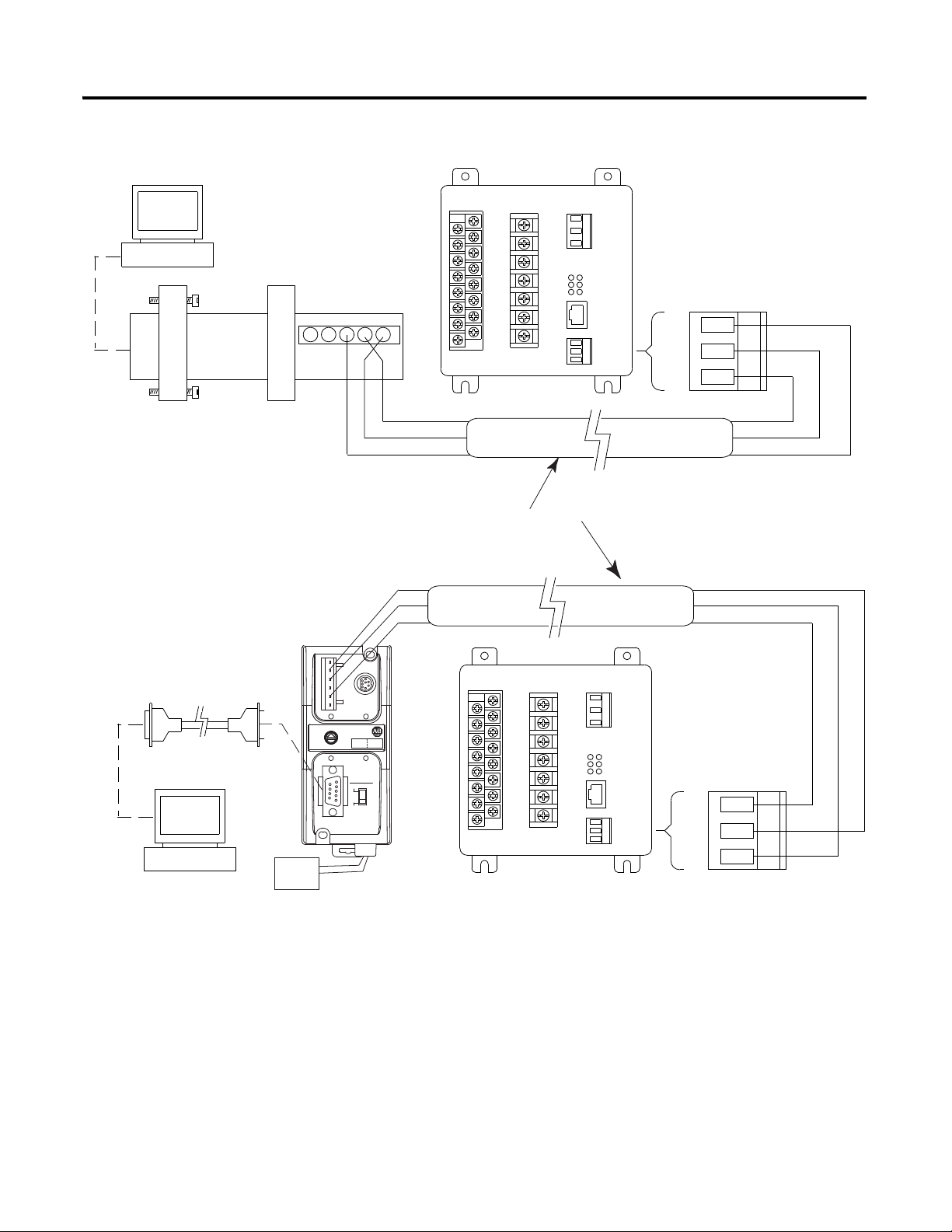
2. Connect an RS-485/RS-232 converter between your PC and the native
RS-485 communications port on the Powermonitor 3000. Figure 1
shows two connection examples. Any RS-232/RS-485 converter that
supports send data control (automatic detection and control of direction
of internal RS-485 driver) can be used. Examples include B&B
Electronics model 485SD9TB and Allen-Bradley catalog number
1761-NET-AIC. Do not use RS-232/RS-485 converters that use the
RTS handshake line to control direction of the internal RS-485 driver.
You may need to apply external +12V power to the B&B converter
when using some laptops.
3. Copy the contents of the CD to your local drive or work directly from
the CD. Run the batch file upgrade.bat to begin the download. Some older
devices may require a power cycle to begin the download process.
4. The download will take approximately six minutes. The green LED’s on
the Master Module should blink and an indication of progress should
appear on your PC monitor during download.
5. Once the progress bar reaches 100%, wait until the Module Status LED
is the only LED illuminated (up to 30 seconds).
6. If your PC did not indicate any error messages and the Master Module
status LED is solid green, the upgrade was successful.
7. Apply the catalog number label included in the upgrade kit to a blank
area on the Master Module nameplate (the white label on the side of the
Master Module which includes a barcode). This label must be affixed to
the unit in the event the device is returned to Allen-Bradley under
warranty.
8. Repeat steps 1 through 7 for each device to be upgraded.
Figure 1 Connecting a PC to a Powermonitor 3000
1 Publication 1404-IN008A-EN-P - August 2002
Page 2
IBM Compatible PC
or Laptop
IBM Compatible PC
or Laptop
Powermonitor 3000 Device
RS-485
SHLD
_
+
Powermonitor 3000 Device
RS-485
SHLD
_
+
24V Power
Supply
Red
Black
BLUE
CLR
SHLD
BLUE
CLR
SHLD
BLUE
CLR
SHLD
BLUE
CLR
SHLD
B & B Electronics
Model 485SD9TB
Allen-Bradley Catalog Number 1770-CD
or Equivalent
Allen-Bradley
Catalog Number 1761-NET-AIC
(AIC+)
Standard Null Modem (9-Pin D) Cable
A
B
GRD
GRD
+12V (If Needed)
2 Powermonitor 3000 Product Upgrade Kit
Publication 1404-IN008A-EN-P - August 2002
Page 3

Powermonitor 3000 Product Upgrade Kit 3
Frequently Asked Questions
Q: Once I have upgraded my product to an M8, are future M8 firmware
updates free?
A: Yes. The latest firmware for each 1404 model is available on the PEMS
website (www.ab.com/PEMS). You can download the latest firmware for your
model and install it for free. If you prefer Allen-Bradley to install the firmware,
there is a service charge.
Q: I have several Ethernet M6 devices currently running on my network. Can
I perform the Powermonitor 3000 product upgrade over Ethernet?
A: No. The model upgrade must be performed using the native RS-485
communication port.
Q: If I upgrade my M5 to an M6, can I upgrade the same unit to an M8 in the
future?
A: Yes. Contact your local Rockwell Automation representative or distributor
to order the M6 to M8 upgrade kit.
Q: After I perform the product upgrade, do I need the CD for future firmware
updates?
A: No. If a newer version of firmware becomes available, you can update your
product with the standard firmware file. For example, if you upgraded your M5
with V1.13 to an M8 with V2.08 and in the future M8 V2.18 became available,
you can perform the firmware update using the M8 V2.18 firmware file
available to the public from our web site.
Q: I have just upgraded my M5 to an M6, has the accuracy class of the device
changed?
A: No. The revenue accuracy class remains the same. If your Powermonitor
3000 was shipped from the factory as a Class 0.5 device, it remains a Class 0.5
device after the upgrade. If your Powermonitor 3000 was shipped from the
factory with Class 1 revenue meter accuracy, it will see an improvement in
accuracy after the upgrade, but is still only verified as a Class 1 device. The
accuracy class is indicated on a label located on the side of the Master Module.
The accuracy class is also indicated on the shipping carton, via the Display
Module (Display - Status - Accuracy Class), and via communications
‘selftest/diagnostic’ results table with Master Modules containing firmware
V2.xx and higher.
Publication 1404-IN008A-EN-P - August 2002
Page 4

Publication 1404-IN008A-EN-P - August 2002 4 PN 40055-214-01(1)
Supersedes Publication XXXX-X.X.X - Month Year Copyright © 2002 Rockwell Automation. All rights reserved. Printed in the U.S.A.
 Loading...