

Page 1
Instruction Sheet
(Cat. No. 1403-DMA or 1403-DMB)
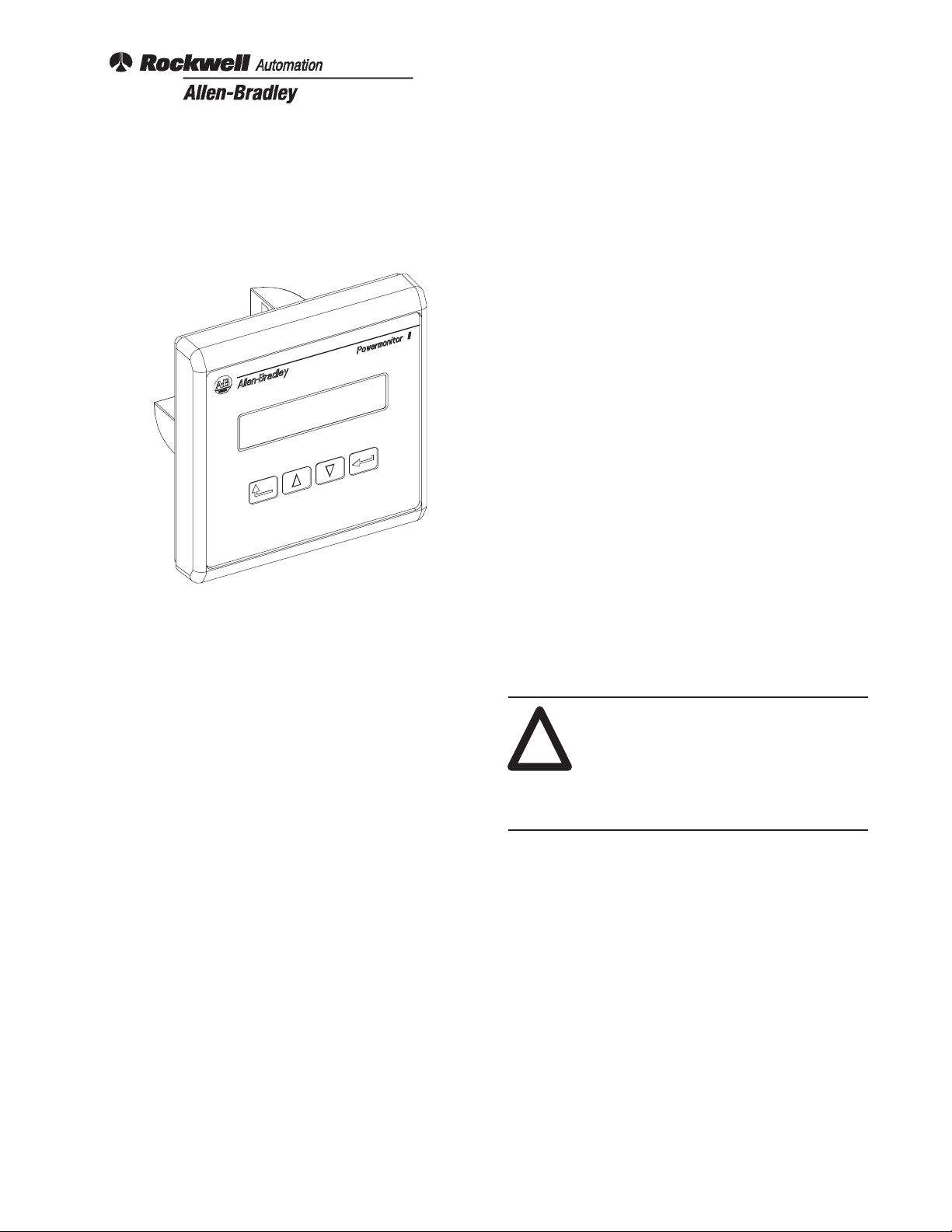
Figure 1. Display Module
Description
The microprocessor based Bulletin 1403 Display
Module, an optional input device, can be used to set up
and configure the Bulletin 1403 Master Module for
operation. This is accomplished through the Display
Module’s front panel which includes four tactile operator
buttons and a liquid crystal display. All communications
between the Display Module and Master Module is
conducted over a serial fiber optic link.
Installation and Orientation The Display Module can be
oriented in any position. The most typical orientation is
shown in Bulletin 1403 Powermonitor II Instruction
Sheet, Publication 1403–5.0, Figure B.1, Appendix B.
The Display Module is designed to fit into the protective
enclosure cutout with a minimum installation depth of
50.8 mm (2.0 in.) behind the mounting panel as shown in
Bulletin 1403 Powermonitor II Instruction Sheet,
Publication 1403–5.0, Figure B.2, Appendix B. The
recommended Display Module mounting hole pattern
and dimensions are defined in Bulletin 1403
Powermonitor II Instruction Sheet, Publication
1403–5.0, Figure B.3, Appendix B. Ensure that the
gasket provided is not contaminated with foreign matter
and is installed in the Display Module correctly. Install
the Display Module into the protective enclosure’s front
panel using the four M4 nut/lockwasher assemblies as
shown in Bulletin 1403 Powermonitor II Instruction
Sheet, Publication 1403–5.0, Figure B.4, in Appendix B.
Tighten the M4 nut/lockwasher assemblies to 0.9 to 1.1
Nm (8 to 10 lb-in.) Note: Eight flat washers are
provided for retrofit applications with larger hole sizes.
ATTENTION: Failure to comply with
these mounting requirements may cause
!
damage to the Display Module or
compromise the IP65 [NEMA/UL 508,
T ype 4X (Indoor)] degree of protection
per International Standard IEC 529.
Mounting of Display Module
Protective Enclosure A suitable enclosure should be
used to protect the Master Module from atmospheric
contaminants such as oil, moisture, dust, and corrosive
vapors or other harmful airborne substances. The
Display Module’ s gasketed front panel interface to the
protective enclosure is rated as an IP65 degree of
protection [National Electrical Manufacturer’s
Association (NEMA)/Underwriter’s Laboratories (UL)
508, T ype 4X (Indoor)] per International Standard IEC
529.
Wiring of Display Module
Power The Display Module can be operated on either
AC or DC power. Two models have been developed to
operate on various AC/DC voltage ranges as defined in
T able A. A single, three-position connector is provided
for all power connections to the Display Module.
Publication 1403-5.2 – September 1996
Page 2
Bulletin 1403 Powermonitor II Display Module2
Table A. Voltage Ratings
Cat. No./
Voltage Range
1403-DMA/High
Voltage
1403-DMB/Low
Voltage
AC Voltages/DC Voltages
(+10% to –20%)
120V/ 240V AC 50/60 Hz or 125V/250V DC
12V/24V AC or 12/24/48V DC
Terminal Block Wire Sizes and Screw T orque Values All
terminal block wire sizes and terminal block screw
torque values are shown in Bulletin 1403 Powermonitor
II Instruction Sheet, Publication 1403–5.0, Appendix C.
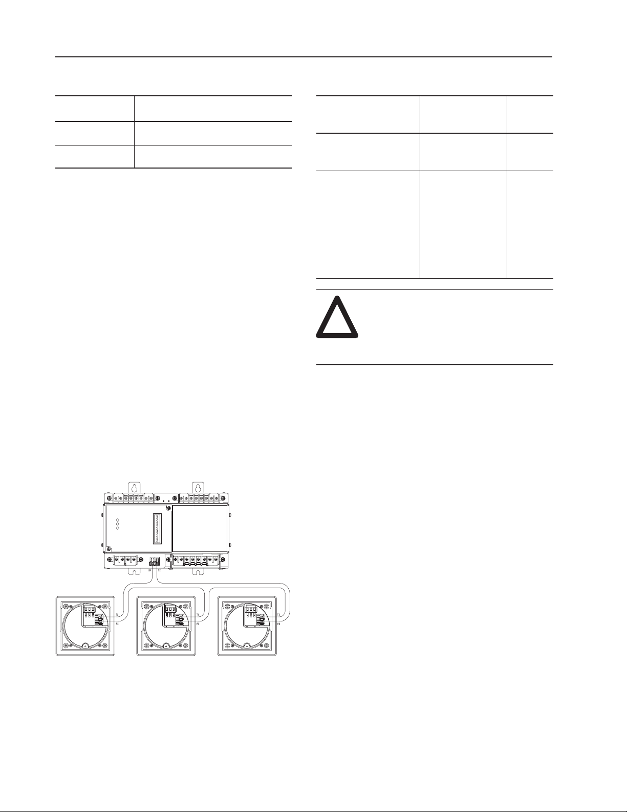
Fiber Optics The Powermonitor II communications
architecture consists of a fiber optic ring between the
Bulletin 1403 Master Module and up to three Display
Modules. The black transmitter component (TX) of a
unit must be connected to the blue receiver (RX)
component of the next unit and repeated for each
additional module until the ring is completed. Figure 2
shows a typical layout of the fiber optic cabling between
one Master Module and three Display Modules. Fiber
optic cable assembly specifications are given in T able B.
Table B. Fiber Optic Cable Assembly Specifications
Parameter
Cable Length:
Distance between two
adjacent devices
Minimum inside bend
radius
Minimum Cable
Length
25 cm (approx. 10 in.)
shortest Allen-Bradley
standard
25.4 mm (1 in.) Any
bends with a shorter
inside radius can
permanently damage
the fiber optic cable.
Signal attenuation
increases with
decreased inside
bend radii.
ATTENTION: Any bend in a fiber optic
cable assembly with an inside radius of
!
less than 25.4 mm (1 in.) may
permanently damage the fiber optic cable
assembly.
Maximum
Cable
Length
500 m
(1650 ft.)
N/A
Important: Always maintain furnished rubber plugs in
the transmitter and receiver when cable
end connectors are not in place. This will
help prevent dirt from contaminating the
transmitter or receiver.
Figure 2. Fiber Optic Communications between a Bulletin 1403
Master Module and Three Display Modules
Publication 1403-5.2 – September 1996
Page 3

Bulletin 1403 Powermonitor II Display Module 3
Fiber Optic Cable Assembly Strain Relief A strain relief
feature at the rear of the Display Module and a wire tie
are provided for securing the fiber optic transmit and
receive cable assemblies. Use the strain relief feature to
protect the fiber optic connections at the rear of the
Display Module. Coil each fiber optic cable into an
approximately one inch diameter loop and secure each
loop to the rear of the Display Module with the wire tie
provided per Figures 3, 4, and 5.
Figure 3. Fiber Optics Strain Relief
Figure 5. Fiber Optics Strain Relief
3. Install and secure both fiber optic cables. The cables
should be coiled into one inch minimum diameter
loops and secured with the wire tie.
Cat. No. Explanation and Accessories See Bulletin 1403
Powermonitor II Instruction Sheet, Publication
1403–5.0, Appendix B for the Display Module Cat. No.
explanation and a listing of all fiber optic accessories.
1. Insert the wire tie into the slot on the Display
Module’s rear cover.
Figure 4. Fiber Optics Strain Relief
2. Push the wire tie into the slot and force it out of the
second, adjacent slot.
Additional Information
Refer to these sections of Bulletin 1403 Powermonitor II
Instruction Sheet, Publication 1403–5.0, for additional
information:
• Chapter 4, General Operation – for configuring the
Master Module using the Display Module
• Appendix B, Mechanical Dimensions
• Appendix C, T echnical Specifications
Publication 1403-5.2 – September 1996
Page 4

Bulletin 1403 Powermonitor II Display Module4
Allen-Bradley, a Rockwell Automation Business, has been helping its customers improve
productivity and quality for more than 90 years. We design, manufacture and support a broad
range of automation products worldwide. They include logic processors, power and motion
control devices, operator interfaces, sensors and a variety of software. Rockwell is one of the
world’s leading technology companies.
Worldwide representation.
Argentina • Australia • Austria • Bahrain • Belgium • Brazil • Bulgaria • Canada • Chile • China, PRC • Colombia • Costa Rica • Croatia • Cyprus • Czech Republic •
Denmark • Ecuador • Egypt • El Salvador • Finland • France • Germany • Greece • Guatemala • Honduras • Hong Kong • Hungary • Iceland • India • Indonesia •
Ireland • Israel • Italy • Jamaica • Japan • Jordan • Korea • Kuwait • Lebanon • Malaysia • Mexico • Netherlands • New Zealand • Norway • Pakistan • Peru •
Philippines • Poland • Portugal • Puerto Rico • Qatar • Romania • Russia–CIS • Saudi Arabia • Singapore • Slovakia • Slovenia • South Africa, Republic • Spain •
Sweden • Switzerland • Taiwan • Thailand • Turkey • United Arab Emirates • United Kingdom • United States • Uruguay • Venezuela • Yugoslavia
Allen-Bradley Headquarters, 1201 South Second Street, Milwaukee, WI 53204 USA, Tel: (1) 414 382-2000 Fax: (1) 414 382-4444
Publication 1403-5.2 – September 1996 40055-163-01 (A)
Publication 1403-5.2 – September 1996
Copyright 1996 Allen-Bradley Company, Inc. Printed in USA
 Loading...