

Page 1

Allen-Bradley
ALLEN-BRADLEY
Line
Synchronization
Module
(Bulletin 1402 LSM)
Installation
and Operation
Manual
Page 2

Important User Information
Solid state equipment has operational characteristics differing from those of
electromechanical equipment. “Safety Guidelines for the Application,
Installation and Maintenance of Solid State Controls” (Publication SGI-1.1)
describes some important differences between solid state equipment and
hard–wired electromechanical devices. Because of this difference, and also
because of the wide variety of uses for solid state equipment, all persons
responsible for applying this equipment must satisfy themselves that each
intended application of this equipment is acceptable.
In no event will the Allen-Bradley Company be responsible or liable for
indirect or consequential damages resulting from the use or application of
this equipment.
The examples and diagrams in this manual are included solely for illustrative
purposes. Because of the many variables and requirements associated with
any particular installation, the Allen-Bradley Company cannot assume
responsibility or liability for actual use based on the examples and diagrams.
No patent liability is assumed by Allen-Bradley Company with respect to use
of information, circuits, equipment, or software described in this manual.
Reproduction of the contents of this manual, in whole or in part, without
written permission of the Allen-Bradley Company is prohibited.
Throughout this manual we use notes to make you aware of safety
considerations.
ATTENTION: Identifies information about practices or
circumstances that can lead to personal injury or death, property
!
damage, or economic loss.
Attentions help you:
• identify a hazard
• avoid the hazard
• recognize the consequences
Important: Identifies information that is especially important for successful
application and understanding of the product.
PLC and PLC–5 are registered trademarks of Allen-Bradley Company, Inc.
ControlView is a trademark of the Allen-Bradley Company, Inc.
Page 3

Table of Contents
Product Description 1–1.
. . . . . . . . . . . . . . . . . . . . . . . . .
Chapter Objectives 1–1. . . . . . . . . . . . . . . . . . . . . . . . . . . . . .
Introduction 1–1. . . . . . . . . . . . . . . . . . . . . . . . . . . . . . . . . . .
General Description 1–1. . . . . . . . . . . . . . . . . . . . . . . . . . . . .
Synchronization and Load Share Errors 1–2. . . . . . . . . . . . . .
Measurements 1–3. . . . . . . . . . . . . . . . . . . . . . . . . . . . . . . . . .
Module Configuration 1–3. . . . . . . . . . . . . . . . . . . . . . . . . . .
Installation 2–1.
. . . . . . . . . . . . . . . . . . . . . . . . . . . . . . . . . .
Location 2–1. . . . . . . . . . . . . . . . . . . . . . . . . . . . . . . . . . . . . .
Enclosure 2–1. . . . . . . . . . . . . . . . . . . . . . . . . . . . . . . . . . . . .
Mounting 2–1. . . . . . . . . . . . . . . . . . . . . . . . . . . . . . . . . . . . .
Power Supply 2–1. . . . . . . . . . . . . . . . . . . . . . . . . . . . . . . . . .
Chassis Grounding 2–1. . . . . . . . . . . . . . . . . . . . . . . . . . . . . .
Swing Arm 2–1. . . . . . . . . . . . . . . . . . . . . . . . . . . . . . . . . . . .
Wiring 2–2. . . . . . . . . . . . . . . . . . . . . . . . . . . . . . . . . . . . . . . .
Prevent Electrostatic Discharge 2–2. . . . . . . . . . . . . . . . .
PT and CT Transformer Selection 2–3. . . . . . . . . . . . . . . . . .
PT Selection 2–3. . . . . . . . . . . . . . . . . . . . . . . . . . . . . . . .
CT Selection 2–3. . . . . . . . . . . . . . . . . . . . . . . . . . . . . . . .
PT and CT Wiring Connections 2–4. . . . . . . . . . . . . . . . . . . .
Connection for Three Phase WYE (Star),
4 Wire Systems 2–4. . . . . . . . . . . . . . . . . . . . . . . . . . . . . .
Connection for Three Phase WYE (Star),
3 Wire Systems 2–4. . . . . . . . . . . . . . . . . . . . . . . . . . . . . .
Connection for Three Phase Delta,
3 Wire Systems with 3 PT’s & 3 CT’S 2–5. . . . . . . . . . . .
Connection for Three Phase Open Delta,
3 Wire Systems with 2 PT’s & 3 CT’S 2–5. . . . . . . . . . . .
Connection for Three Phase Open Delta,
3 Wire Systems with 2 PT’s & 2 CT’S 2–5. . . . . . . . . . . .
Neutral Connection 2–5. . . . . . . . . . . . . . . . . . . . . . . . . . .
Current Transformer Connections 2–6. . . . . . . . . . . . . . .
Maintenance 2–6. . . . . . . . . . . . . . . . . . . . . . . . . . . . . . . . . . .
Calibration 2–6. . . . . . . . . . . . . . . . . . . . . . . . . . . . . . . . . . . .
Field Service Considerations 2–6. . . . . . . . . . . . . . . . . . . . . .
General Operation 3–1.
. . . . . . . . . . . . . . . . . . . . . . . . . . .
Chapter Objectives 3–1. . . . . . . . . . . . . . . . . . . . . . . . . . . . . .
Operational Characteristics 3–1. . . . . . . . . . . . . . . . . . . . . . .
Functional 3–1. . . . . . . . . . . . . . . . . . . . . . . . . . . . . . . . . .
Configuration 3–1. . . . . . . . . . . . . . . . . . . . . . . . . . . .
Synchronization 3–4. . . . . . . . . . . . . . . . . . . . . . . . . .
Power Monitoring 3–6. . . . . . . . . . . . . . . . . . . . . . . . .
Load Sharing 3–7. . . . . . . . . . . . . . . . . . . . . . . . . . . . .
Control 3–8. . . . . . . . . . . . . . . . . . . . . . . . . . . . . . . . .
Self–test 3–8. . . . . . . . . . . . . . . . . . . . . . . . . . . . . . . .
Update Rate 3–9. . . . . . . . . . . . . . . . . . . . . . . . . . . . . . . .
Accuracy 3–9. . . . . . . . . . . . . . . . . . . . . . . . . . . . . . . . . . .
i
Page 4

T
able of Contents
PLC Interface 3–9. . . . . . . . . . . . . . . . . . . . . . . . . . . . . . . . . .
Discrete I/O Interface 3–9. . . . . . . . . . . . . . . . . . . . . . . . .
Discrete Outputs (From the PLC Processor) 3–10. . . .
Discrete Inputs (To the PLC Processor) 3–10. . . . . . . .
Block Transfer Data Interface 3–10. . . . . . . . . . . . . . . . . . .
Configuration Software Support 3–11. . . . . . . . . . . . . . . . .
6200 Software 3–11. . . . . . . . . . . . . . . . . . . . . . . . . . . .
Application Information 4–1.
. . . . . . . . . . . . . . . . . . . . . .
Overview 4–1. . . . . . . . . . . . . . . . . . . . . . . . . . . . . . . . . . . . .
Modes of Operation 4–1. . . . . . . . . . . . . . . . . . . . . . . . . .
Monitor Only 4–1. . . . . . . . . . . . . . . . . . . . . . . . . . . .
Monitor with Load Share 4–1. . . . . . . . . . . . . . . . . . .
Synchronization and Monitor 4–1. . . . . . . . . . . . . . . .
Synchronization and Monitor with Load Share 4–2. .
Interfacing to the LSM 4–2. . . . . . . . . . . . . . . . . . . . . . . . . . .
Block Transfer Communications 4–2. . . . . . . . . . . . . . . .
Configuration 4–3. . . . . . . . . . . . . . . . . . . . . . . . . . . .
Acquiring Data From the LSM 4–4. . . . . . . . . . . . . . .
Discrete Input / Output Control of the LSM 4–4. . . . . . . .
Discrete Outputs From The PLC–5 4–4. . . . . . . . . . .
Discrete Inputs to the PLC–5 4–6. . . . . . . . . . . . . . . .
Ladder Program Description 4–8. . . . . . . . . . . . . . . . . . . . . .
Data Files Used 4–9. . . . . . . . . . . . . . . . . . . . . . . . . . . . . .
Accessing BTR Data from PLC Ladder 4–11. . . . . . . . . . .
Catalog Number Explanation A–1.
. . . . . . . . . . . . . . . . . . .
Line Synchronization Module A–1.
Block Transfer and Discrete I/O Definition B–1.
Sample Ladder Listing C–1.
. . . . . . . . . . . . . . . . . . .
. . . . . . .
. . . . . . . . . . . . . . . . . . . . . . . .
Line Synchronization Module
Mechanical Dimensions D–1.
Bulletin 1402 Technical Specifications E–1.
. . . . . . . . . . . . . . . . . . . . . . .
. . . . . . . . . . .
CSA Hazardouis Location Approval E–2. . . . . . . . . . . . . . . .
Compliance to European Union Directives E–4. . . . . . . . . . .
ii
Page 5

Using This Manual
Preface
A–B
What This Manual Contains
Review the table below to familiarize yourself with the topics contained in
this manual.
For information about: Refer to chapter:
Product features and System applications
Synchronization Functions
Extensive Array of Monitoring Information
Installing the Line Synchronization Module
Wiring and Transformer Selection
Operational Characteristics
PLC Interface
Configuration Software Support – 6200 Software
Modes of Operation
Block Transfer Communications
Configuration Information
Ladder Program Description
Catalog Number Explanation Appendix A
Block Transfer and Discrete I/O Definition Appendix B
Sample Ladder Listing Appendix C
Mechanical Dimensions Appendix D
Technical Specifications Appendix E
1
2
3
4
For More Information on Additional Power Quality Products
For this information: Refer to:
Catalog Number 1400–PD Installation and Operation Manual Publication 1400–5.2
Catalog Number 1400–SP Installation and Operation Manual Publication 1400–801
Installing the Communications Card Instructions
Catalog Number 1400–DCU
RS–232C and RS–485 Convertor Instructions
Catalog Number 1400–CC
LSM Application Notes Publication 1402Catalog Number 1403-MM Powermonitor II Instruction Sheet Publication 1403-5.0
Catalog Number 1003-NSC Smart Communications Card
Instruction Sheet
Powermonitor II Tutorial Publication 1403-1.0.2
Publication
1400–5.0
Publication
1400–5.1
Publication 1403-5.1
i
Page 6

Preface
Using This Manual
Terms and Conventions
In this manual, the following terms and conventions are used:
Abbreviation Term
AWG American Wire Gage
BTR Block Transfer Read
BTW Block Transfer Write
CT Current Transformer
EEPROM Electrically Erasable Programmable ROM
EMI Electromagnetic Interference
ID Identification
LED Light Emitting Diode
I/O Inputs and Outputs should be considered with respect to the PLC processor
LSM Line Synchronization Module
PT Potential Transformer
RAM Random Access Memory
RFI Radio Frequency Interference
RMS Root–mean–square
ROM Read Only Memory
VA Volt–ampere
VAR Volt–ampere Reactive
ii
Page 7

Chapter
Chapter
Objectives
Introduction
A–B
1
Product Description
After reading this chapter, you should be able to identify the product features
and system applications.
The Bulletin 1402, Line Synchronization Module (LSM), is designed to meet
the needs of manufacturers, system integrators, and users of 3 phase
alternators and cogeneration systems or for applications that require two
three–phase systems to be synchronized with each other. The module
provides means for automatic synchronization, load sharing, and high speed
power system monitoring.
General Description
The Line Synchronization Module (LSM) is a two slot 1771 form factor
module that fits into a standard Allen–Bradley 1771 I/O chassis. It performs
three functions:
1. Measures appropriate parameters from the two three–phase systems and
provides control and error signals to implement engine governor control
for synchronization.
2. Provides an analog output that is representative of the ratio of the power
being supplied by the alternator to the output rating of the alternator,
reads an analog input that represents the ratio of the total system load
being supplied to the total system capacity, and provides an error signal to
adjust the alternator for proper load sharing based on the instantaneous
load requirements.
3. Performs as a multi–function digital power monitor for the system.
These functions provide data and control signals which are communicated to
the PLC-5 via the 1771 backplane.
1–1
Page 8

Chapter 1
Product Description
Synchronization and Load Share Errors
In order to synchronize two three phase systems without high instantaneous
energy transfer, the voltage, frequency, and phase displacement of the two
systems must be matched. Kilowatt Load Sharing can be implemented by
matching the ratio of power system load to system capacity to the ratio of
actual alternator power to rated alternator power. The LSM provides the
following information to allow the user’s system to achieve the necessary
control actions.
• Voltage Match Error (in steps of 0.05 percent)
• Frequency Match Error, or slip (in steps of 0.01 Hz)
• Synchronizing Bus to Reference Bus Phase Match Error (in steps of 1
degree)
• Load Sharing Error (scalar quantity between 0.000 and 1.000)
• Synchronization Status
— Frequency Within Limits
— Voltage Within Limits
— Phase Within Limits
— Synchronization Mode Conflict Failure
— Phase Rotation Mismatch Failure (3 phase synchronization mode only)
— No Reference Bus Voltage Present Failure
— No Synchronizing Bus Voltage Present Failure
— Reference Bus Over Voltage Failure
— Synchronizing Bus Over Voltage Failure
1–2
Page 9

Chapter 1
Product Description
Measurements
Synchronizing Bus
Synchronizing Bus
Reference Bus
In addition to the synchronization function, the LSM provides an extensive
array of monitoring information for systems wired in Wye, Delta, or Open
Delta. The monitored data is shown below:
T
able 1.1
Current in Amps (per phase & neutral)
Average Current in Amps
Positive Sequence Current in Amps
Negative Sequence Current in Amps
Percent Current Unbalance
Voltage in Volts (per phase L–L, also L–N on 4–wire systems)
Average Voltage in Volts (L–L, also L–N on 4–wire systems)
Positive Sequence Voltage in Volts
Negative Sequence Voltage in Volts
Percent Voltage Unbalance
Frequency in Hz
Phase Rotation (ABC, ACB)
Power Factor in Percent (total, also per phase on 4–wire systems)
Watts (total & per phase on 4–wire systems)
VA (total & per phase on 4–wire systems)
VAR (total & per phase on 4–wire systems)
Power Consumption in kW Hours
Reactive Power Consumption in kVAR Hours
Demand (Amps, VA, & Watts)
Voltage per phase in Volts (per phase L–L, also L–N on 4–wire systems)
Average Voltage in Volts (L–L, also L–N on 4–wire systems)
Frequency in Hz
Phase Rotation (ABC, ACB)
Module Configuration
All voltage and current measurements are true RMS. The power
measurements are calculated from the instantaneous voltage and current
measurements. The remainder of the monitoring information is derived from
these values.
Before the LSM can perform its intended functions, it must be configured by
the user. The module is configured by providing the required data via a block
transfer to the module. The block transfer data can be entered into the PLC-5
manually or with the 6200 Version 4.4 I/O Configuration Software. The 6200
Software can also be used to monitor the operation of the module.
1–3
Page 10

Chapter 1
Product Description
1–4
Page 11

Chapter
Location
Enclosure
A–B
2
Installation
The Bulletin 1402 Line Synchronization Module (LSM) should be installed
in a Bulletin 1771 I/O chassis that is located in a dry, dirt free environment
away from heat sources and very high electric or magnetic fields. The
module is designed to operate in an ambient temperature between 0 and 60°
Celsius. The LSM is typically installed in a local rack in order to maximize
data transfer rates.
This equipment is classified as open equipment and must be installed
(mounted in an enclosure during operation as a means of providing safety
protection. The enclosure chosen should protect the LSM from atmospheric
contaminants such as oil, moisture, dust, corrosive vapors, or other harmful
airborne substances. A steel enclosure is recommended to guard against EMI
(Electromagnetic Interference) & RFI (Radio Frequency Interference).
Mounting
Power Supply
Chassis Grounding
The enclosure should be mounted in a position that allows the doors to open
fully. This will allow easy access to the wiring of the LSM and related
components so that servicing is convenient.
When choosing the enclosure size, extra space should be allowed for
associated application equipment such as, transformers, fusing, disconnect
switch, master control relay, and terminal strips.
The LSM mounts in two slots of a Bulletin 1771 Series B, I/O chassis.
Mounting dimensions will vary with the size of the chassis selected. Refer to
the appropriate 1771 literature for specific dimensions.
The LSM backplane power requirement is 1.1A at 5V DC. Refer to the
appropriate 1771 literature for additional information on available power
supply current.
For correct and reliable performance, the grounding recommendations
specified for Allen–Bradley PLC systems must be followed.
2–1
Page 12

Chapter 2
Installation
Swing Arm
Wiring
The LSM requires the use of a Cat. No. 1771-WC (10 position, gold
contacts) Swing Arm.
There are two sets of terminals associated with the LSM; a 10 position
swingarm and an 8 position fixed terminal block. All customer wiring to the
LSM is accomplished via these terminals on the front of the module. The
10–position swingarm is used to make all of the voltage (PT) connections to
the module as well as the Load Share connections. These connections are
designed to accommodate wire size 0.5 mm
2
mm
(14 AWG). The 8–position fixed terminal block is used to make all of
the current (CT) connections. These connections are designed to
accommodate gauge wire size 0.5 mm
3.25 mm
Phasing and polarity of the AC current and voltage inputs and their
relationship are critical for the correct operation of the unit. Figure 2.1
through Figure 2.5 shown on Pages 2–7 through 2–11 provide wiring
diagrams to help ensure correct installation.
Two (2) conductor shielded wire (22 gauge or greater) should be used for
Load Share wiring. The shield shall be grounded at the PLC Chassis ground
point only.
2
(12 AWG).
2
(22 AWG) through size 2.0
2
(22 AWG) through ring lugs size
Prevent Electrostatic Discharge
ATTENTION: Electrostatic discharge can damage integrated
circuits or semiconductors if you touch backplane connector pins.
!
Follow these guidelines when you handle the module:
• Touch a grounded object to discharge static potential.
• Wear an approved wrist-strap grounding device.
• Do not touch the backplane connector or connector pins.
• Do not touch circuit components inside the module.
• If available, use a static-safe work station.
• When not in use, keep the module in its static-shield box.
2–2
Page 13

Chapter 2
Installation
PT and CT Transformer Selection
For proper monitoring and synchronization, correct selection of current
transformers (CT’s) and potential transformers (PT’s) is critical. The
following paragraphs provide the information required to choose these
transformers. Also refer to transformer operational characteristics Pages 3–2
and “Factory Configuration Parameters” listed on Page B–2.
PT Selection
The LSM is designed for a nominal full scale input voltage of 120V AC. The
user must supply transformers to scale down the system L–N (Wye) or L–L
(Delta) voltage to the full scale input rating of the module. The PT’s should
be selected as follows:
• Wye (Star) Configuration – PT primary rating = L–N voltage or nearest
higher standard size. PT secondary rating = 120 Volts.
• Delta or Open–Delta Configuration – PT primary rating = system L–L
voltage. PT secondary rating = 120 Volts.
PT quality directly affects system accuracy. The PT’s must provide accurate
linearity and maintain the proper phase relationship between voltage and
current in order for the Phase Error, Volts, kW, and Power Factor readings to
be valid. Instrument accuracy Class 1 or better is recommended. The LSM
PT inputs represent a O.O2 VA burden.
CT Selection
The LSM uses current transformers (CT’s) to sense the current in each phase
of the power feed from the synchronizing voltage source, and may optionally
be included in the ground or neutral conductor. The precision of the selected
CT’s will directly affect the device accuracy.
The CT secondary should have a rating of 5A full scale and a burden
capacity greater than 3VA. The LSM Module CT Inputs represent a burden
of 0.0025VA.
ATTENTION: The CT primary rating is normally selected to be
equal to the current rating of the power feed protection device.
However, if the peak anticipated load is much less than the rated
!
system capacity, then improved accuracy and resolution can be
obtained by selecting a lower rated CT. Generally, the CT size
should be the maximum expected peak current +25%, rounded
up to the nearest standard CT size.
2–3
Page 14

Chapter 2
PT an
ing Connections
Installation
Other factors may affect CT accuracy. The length of the CT cabling should
be minimized because long cabling could contribute to excessive power load
on the CT and inaccuracy. The CT burden rating must exceed the combined
burden of the LSM plus cabling plus any other devices connected in the
measuring circuit (burden is the amount of load being fed by the CT,
measured in Volt–Amps calculated at 5A full scale.).
Overall accuracy is dependent on the combined accuracy of the Bulletin
1402, the CT’s, and the PT’s. Instrument accuracy Class 1 or better is
recommended.
ATTENTION: A CT circuit must not be opened under power.
Wiring between the CT’s and the LSM should include a terminal
!
block for shorting the CT’s. Open CT’s secondaries can produce
hazardous voltages, which can lead to personal injury or death,
property damage or economic loss.
d CT Wir
Connection for Three Phase WYE (Star), 4 Wire Systems
Figure 2.1 shown on Page 2–7 provides a wiring diagram for 4–wire WYE
(Star) systems. The “Voltage Mode” of the LSM should be set to “1” (as
described in Chapter 3, “General Operation”) for 4–wire WYE systems.
The LSM senses the line to neutral (or ground) voltage of each phase. The
PT primaries and secondaries must be wired in a WYE (Star) configuration
as shown in the figure. Voltage input leads should be protected by circuit
breakers or fuses at their source. If the power rating of the PT’s is over 25
Watts, secondary fuses should be used. Wiring and polarity marks must be
exactly as shown for correct operation.
Connection for Three Phase WYE (Star), 3 Wire Systems
Figure 2.2 shown on Page 2–8 provides a wiring diagram for 3–wire WYE
(Star) systems. The “Voltage Mode” of the LSM should be set to “1” (as
described in Chapter 3, “General Operation”) for 3–wire WYE systems.
The LSM senses the line to neutral voltage of each phase. The PT primaries
and secondaries must be wired in a WYE (Star) configuration as shown in
the figure. Voltage input leads should be protected by circuit breakers or
fuses at their source. If the power rating of the PT’s is over 25 Watts,
secondary fuses should be used. Wiring and polarity marks must be exactly
as shown for correct operation.
2–4
Page 15

Chapter 2
PT an
ing Connections
Installation
d CT Wir
Continued
Connection for Three Phase Delta, 3 Wire Systems with 3 PT’s & 3 CT’S
When configured for ungrounded (floating) Delta operation, the LSM senses
the L–L voltages between each of the phases. The “Voltage Mode” of the
LSM should be set to “2” (as described in Chapter 3, “General Operation”).
Figure 2.3 shown on Page 2–9 provides the wiring diagram for this
configuration. Wiring and polarity marks must be exactly as shown for
correct operation.
Connection for Three Phase Open Delta, 3 Wire Systems with
2 PT’s & 3 CT’S
When configured for ungrounded or Open Delta operation, the LSM senses
the L–L voltages between each of the phases. The “Voltage Mode” of the
LSM should be set to “4” (as described in Chapter 3, “General Operation”).
Figure 2.4 shown on Page 2–10 provides the wiring diagram for this
configuration. Wiring and polarity marks must be exactly as shown for
correct operation.
Connection for Three Phase Open Delta, 3 Wire Systems with
2 PT’s & 2 CT’S
When configured for ungrounded (floating) Open Delta operation, the LSM
senses the L–L voltages between each of the phases. The “Voltage Mode” of
the LSM should be set to “4” (as described in Chapter 3, “General
Operation”). Figure 2.5 shown on Page 2–11 provides the wiring diagram for
this configuration. Wiring and polarity marks must be exactly as shown for
correct operation.
Neutral Connection
The voltage reference terminal, “Neutral”, of the LSM serves as the zero
voltage reference for voltage readings. A low impedance Neutral connection
is essential for accurate measurement. The length of the wire should be as
short as possible. It should be made using a dedicated size 2.0 mm
AWG) wire, or larger, to a point in close proximity to the LSM. This will
provide minimal voltage error due to other distribution voltage drops.
The connection point for “Neutral” is the point where the PT secondary leads
are common.
2
(14
2–5
Page 16

Chapter 2
Installation
Current Transformer Connections
The LSM is equipped with four CT inputs, designated I1 – I4. Inputs I1 – I3
are used to measure the current in the synchronizing circuit. These inputs are
wired as shown on Pages 2–7 through 2–11 in Figure 2.1 through Figure 2.5.
Input I4 is optional and is typically used to measure current in the neutral or
ground conductor. The primary rating for I4 can be different than the primary
rating for transformers I1 – I3. However, the secondary rating for all of the
CT’s must be 5 Amps.
Current connections may remain unused for a system that only performs
synchronization. Unused terminals should be wired to chassis ground for
noise immunity.
Maintenance
Calibration
Field
Service Considerations
The LSM does not require any special maintenance.
The calibration interval for the LSM depends on the user’s accuracy
requirements. To meet general operating requirements, regular calibration is
not necessary.
Contact your nearest Allen–Bradley Sales Office for calibration or service
information.
If the LSM requires servicing, please contact your nearest Allen-Bradley
Sales Office. To minimize your inconvenience, the initial installation should
be performed in a manner which makes removal easy.
1. A CT shorting block should be provided to allow the LSM current inputs
to be disconnected without open circuiting the user supplied CTs. The
shorting block should be wired to prevent any effect on the external
protective relays.
2. All wiring should be routed to allow easy maintenance at connections to
the LSM terminal strips, the swing-arm, and the LSM itself.
2–6
ATTENTION: A CT circuit must not be opened with primary
current present.. Wiring between the CT’s should include a
!
terminal block for shorting the CT’s. Open CT secondaries will
produce hazardous voltages, which can lead to personal injury or
death, property damage, economic loss or CT failure.
Page 17
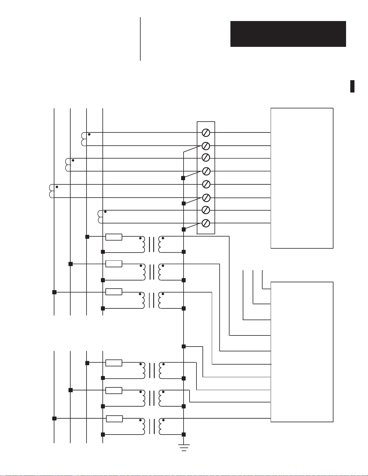
Chapter 2
Installation
Synchronizing
L1 L2 L3 N
CT
CT
Bus V
oltage
CT
Fuse
Fuse
Fuse
Figure 2.1
PT
PT
PT
– Wiring Diagram for 4–Wire Wye Connection
Customer Supplied
CT Shorting Switch
or T
est Block
Load Share Circuit
1
L3+
2
L3–
3
L2+
4
L2–
5
L1+
6
L1–
7
Neutral +
Neutral –
8
A
Load Share +
0
Load Share –
LSM
CT Terminal Block
LSM
Swingarm
Reference Bus V
L1 L2 L3 N
oltage
Fuse
Fuse
Fuse
PT
PT
PT
NOTE: See Appendix E for CE compliant wiring requirements.
Customer Chassis
Ground
1
Load Share Shield
No Internal Connection
2
Synchronizing Bus V3
3
Synchronizing Bus V2
4
Synchronizing Bus V1
5
Neutral
6
Reference Bus V3
7
Reference Bus V2
B
Reference Bus V1
2–7
Page 18
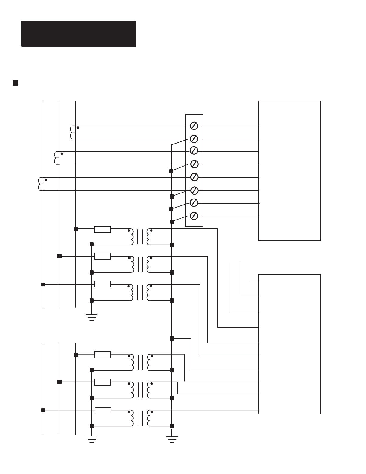
Chapter 2
Installation
Synchronizing
L1 L2 L3
CT
Bus V
CT
oltage
CT
Fuse
Fuse
Fuse
Figure 2.2
PT
PT
PT
– Wiring Diagram for 3–Wire Wye Connection
Customer Supplied
CT Shorting Switch
est Block
or T
1
4
5
6
7
Load Share Circuit
A
L3+
2
L3–
3
L2+
L2–
L1+
L1–
Neutral +
Neutral –
8
Load Share +
0
Load Share –
LSM
CT Terminal Block
LSM
Swingarm
2–8
Reference Bus V
L1 L2 L3
oltage
Fuse
Fuse
Fuse
PT
PT
PT
NOTE: See Appendix E for CE compliant wiring requirements.
Customer Chassis
Ground
1
Load Share Shield
No Internal Connection
2
Synchronizing Bus V3
3
Synchronizing Bus V2
4
Synchronizing Bus V1
5
Neutral
6
Reference Bus V3
7
Reference Bus V2
B
Reference Bus V1
Page 19
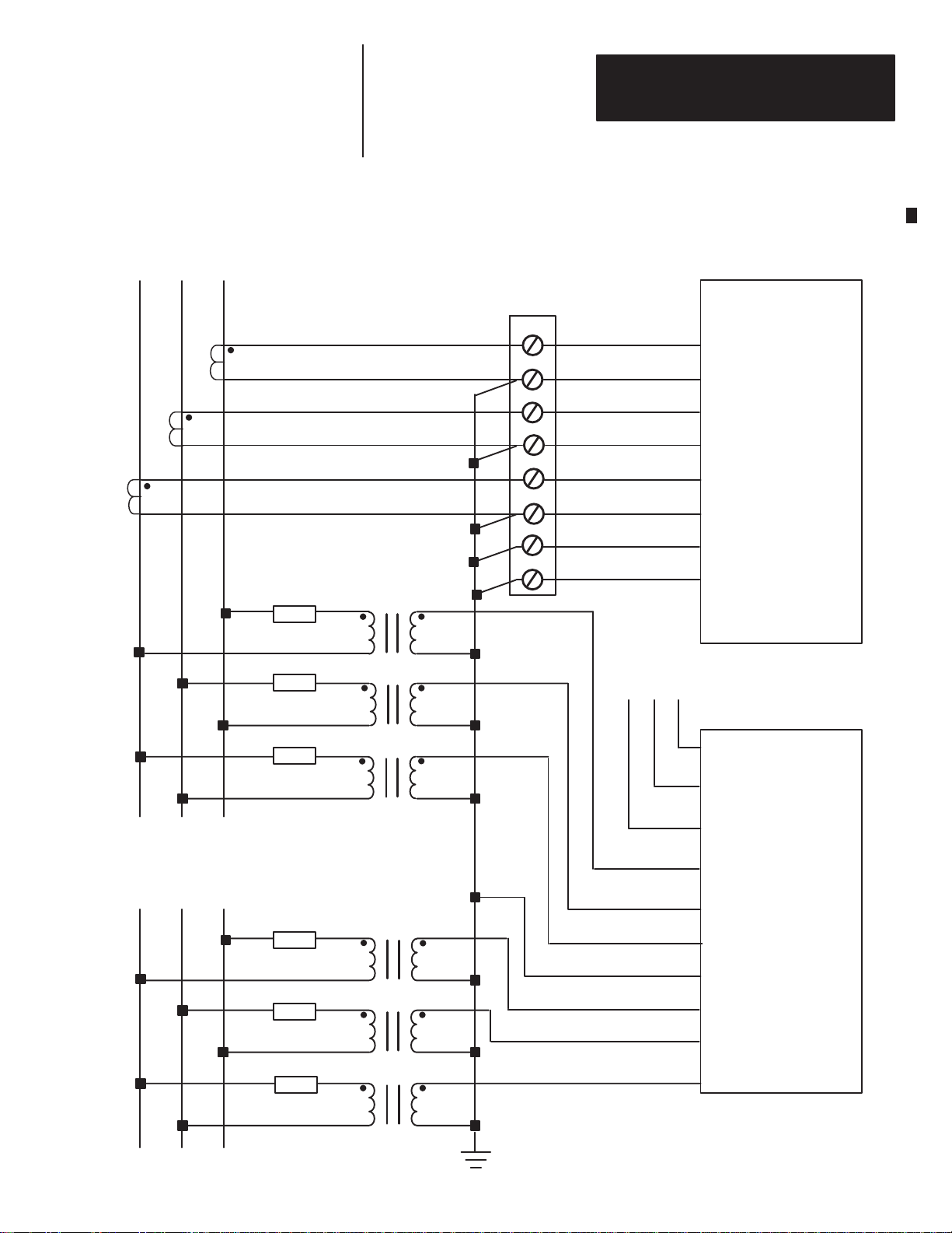
Chapter 2
Installation
Synchronizing
L1 L2 L3
CT
Bus V
CT
oltage
CT
Fuse
Figure 2.3
PT
– Wiring Diagram for 3 Transformer Delta Connection
Customer Supplied
CT Shorting Switch
or T
est Block
1
2
3
4
5
6
7
8
L3+
L3–
L2+
L2–
L1+
L1–
Neutral +
Neutral –
CT Terminal Block
LSM
Reference Bus V
L1 L2 L3
oltage
Fuse
Fuse
Fuse
Fuse
Fuse
PT
PT
PT
PT
PT
NOTE: See Appendix E for CE compliant wiring requirements.
Customer Chassis
Ground
Load Share Circuit
A
0
1
2
3
4
5
6
7
B
LSM
Swingarm
Load Share +
Load Share –
Load Share Shield
No Internal Connection
Synchronizing Bus V3
Synchronizing Bus V2
Synchronizing Bus V1
Neutral
Reference Bus V3
Reference Bus V2
Reference Bus V1
2–9
Page 20
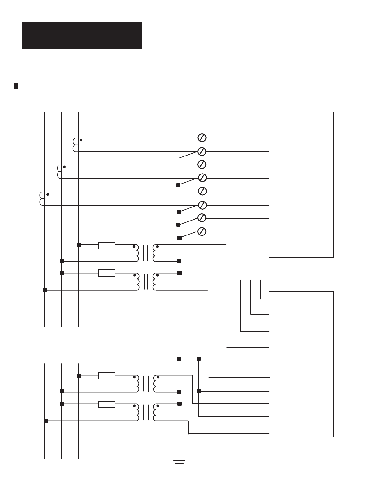
Chapter 2
Installation
Synchronizing
L1 L2 L3
CT
Bus V
CT
oltage
CT
Fuse
Figure 2.4
PT
– Wiring Diagram for 2 Transformer Open–Delta Connection
Customer Supplied
CT Shorting Switch
or T
est Block
1
2
3
4
5
6
7
8
L3+
L3–
L2+
L2–
L1+
L1–
Neutral +
Neutral –
LSM
CT Terminal Block
Reference Bus V
L1 L2 L3
oltage
Fuse
Fuse
Fuse
PT
PT
PT
NOTE: See Appendix E for CE compliant wiring requirements.
Customer Chassis
Ground
Load Share Circuit
A
0
1
2
3
4
5
6
7
B
LSM
Swingarm
Load Share +
Load Share –
Load Share Shield
No Internal Connection
Synchronizing Bus V3
Synchronizing Bus V2
Synchronizing Bus V1
Neutral
Reference Bus V3
Reference Bus V2
Reference Bus V1
2–10
Page 21

Chapter 2
Installation
Synchronizing
L1 L2 L3
CT
Bus V
oltage
CT
Fuse
Figure 2.5
PT
– Wiring Diagram for 2 Transformer Open–Delta Connection With 2 CT’
Customer Supplied
CT Shorting Switch
est Block
or T
1
2
3
4
5
6
7
8
L3+
L3–
L2+
L2–
L1+
L1–
Neutral +
Neutral –
LSM
CT Terminal Block
s
Reference Bus V
L1 L2 L3
oltage
Fuse
Fuse
Fuse
PT
PT
PT
NOTE: See Appendix E for CE compliant wiring requirements.
Customer Chassis
Ground
Load Share Circuit
A
0
1
2
3
4
5
6
7
B
LSM
Swingarm
Load Share +
Load Share –
Load Share Shield
No Internal Connection
Synchronizing Bus V3
Synchronizing Bus V2
Synchronizing Bus V1
Neutral
Reference Bus V3
Reference Bus V2
Reference Bus V1
2–11
Page 22

Chapter 2
Installation
2–12
Page 23

Chapter
ational
acteristics
Chapter
Oper
Objectives
Char
A–B
3
General Operation
This chapter:
• introduces the user to the controls and operation
• describes each function
• defines operating parameters
Functional
The LSM has six different modes of operation. These modes are described
below.
Configuration
Before the LSM can perform its intended functions, it must be configured by
the integrator/OEM or user. Configuration is accomplished by sending the
appropriate information to the module via the “Block Transfer Write”
mechanism. Configuration data is compared with acceptable values. The user
can obtain acknowledgment of the configuration data by using the “Block
Transfer Read” mechanism for access to the module’s response. If
out–of–range or illegal values were entered, an error indication that identifies
the illegal or out–of–range entries is returned. If the data is acceptable, an
acknowledgment indication is returned. The new configuration data is then
used to scale the monitoring data and to set up the synchronization and load
sharing functions.
Whenever new configuration data is sent to the LSM, all module functions
(synchronization, load–sharing, and monitoring) are terminated, and the
values for “Amps Demand”, “kVA Demand”, and “kW Demand” are cleared.
The values for “kW Hours” and “kVAR Hours” are maintained at the values
present before the new configuration data was sent. The new configuration
data is then evaluated. Upon acceptance of the new configuration data, the
module resumes normal operation.
A detailed description of the required configuration data follows. See “Block
Transfer Communications”, on Page 4–2 in the Application Information
chapter of this manual and Appendix B, “Block Transfer Tables and Discrete
I/O Definition”, for a detailed description of how the module performs block
transfers and how the associated data is organized.
3–1
Page 24

Chapter 3
ational
acteristics
General Operation
Oper
Continued
Char
Voltage Mode
This entry is used to indicate if the system being monitored is wired in a
WYE, a Delta, or an open Delta. A value of “1” will indicate a WYE
system, a value of “2” will indicate a three transformer Delta system, and
a value of “4” will indicate a two transformer Open Delta system.
Line–to–Neutral values will be provided only when a WYE is configured.
PT Primary Rating
This entry is used to indicate the primary voltage rating of the user
supplied potential transformers. This information is used for scaling
purposes. The value of this parameter must be between 120 and 115,000.
Line and Neutral CT Primary Ratings
These entries are used to indicate the primary ampere rating of the user
supplied line and neutral current transformers. This information is used
for scaling purposes. The value of this parameter must be between 5 and
10,000.
Synchronization Method
This configuration entry is used to indicate which method of
synchronization is to be implemented. A value of “0” indicates the
delayed acceptance window method.
3–2
ATTENTION: The following acceptance limit values must be
set to fit the customer applications.
!
Voltage Match Error Upper and Lower Acceptance Limits
These entries are used to specify the upper and lower acceptance limits
for matching Synchronizing Bus voltage to the Reference Bus voltage.
The value is specified in steps of 0.05% and must be between 0.00 and
25.00 percent.
Frequency Match Error Upper and Lower Acceptance Limits
These entries are used to specify the upper and lower acceptance limits
for matching Synchronizing Bus frequency to the Reference Bus
frequency. The value is specified in steps of 0.01 Hz and must be between
0.00 and 1.00.
Page 25

Chapter 3
ational
acteristics
General Operation
Oper
Continued
Char
Phase Match Error Upper and Lower Acceptance Limits
These entries are used to specify the upper and lower acceptance limits
for matching Synchronizing Bus phasing to the Reference Bus phasing.
The value is specified in degrees and must be between 0 and 45.
Acceptance Window Delay
This entry is used for the delayed acceptance window method of
synchronization. The value is specified in steps of 0.05 seconds and must
be between 0.00 and 10.00.
Maximum Synchronizing Bus Output Power
This entry is used to specify the power level at which the load sharing
output voltage will be at its maximum value. The ratio of the actual power
output to the value of this parameter is used to adjust the load sharing
output voltage. This value will be specified in kW and must be between 0
and 999,999.
Load Share Full–scale Voltage
This entry is used to specify the load share circuit’s full scale output
voltage. The value is specified in steps of 0.01 volts and must be between
2.00 and 4.00.
Load Share Excess
This entry is used to specify the threshold for initiating action to decrease
the Synchronizing Bus output power to the appropriate portion of the total
system load. The value is a scalar quantity between 0.000 and –0.500.
Load Share Deficit
This entry is used to specify the threshold for initiating action to increase
the Synchronizing Bus output power to the appropriate percentage of the
total system load. The value is a scalar quantity between 0.000 and
+0.500.
3–3
Page 26

Chapter 3
ational
acteristics
General Operation
Oper
Continued
Char
Demand Period
This entry is used to specify the desired period for demand measurement.
The value is specified in minutes and must be between 1 and 99.
Number Of Demand Periods
This entry specifies the number of demand periods that should be
averaged to determine the actual demand. The value must be between 1
and 15.
Synchronization
functionality of the synchronization process is based on the
The
synchronization discrete outputs from the PLC–5 received via the PLC
backplane. The “Initiate Synchronization” output from the PLC–5 begins the
synchronization process when it is asserted. It must remain asserted during the
entire process. If the initiate signal is removed, the synchronization process is
terminated. In addition to the initiate signal, one of the
“Auto–Synchronization”, “Check Synchronization”, or the “Permissive
Synchronization” discrete outputs from the PLC–5 must be asserted. If more
than one of those signals is present, the synchronization fails and the
“Synchronization Failure” discrete input to the PLC–5 will be asserted.
Additional information pertaining to the cause of the failure may be obtained
by reading the appropriate block transfer data from the “Synchronizing Bus
Error Parameters” table. (See Appendix B, “Block T
Definition”, for additional information.) If new setup information is received
via block transfer while the LSM is in the Synchronization mode,
synchronization is terminated. The new configuration data is evaluated and
normal operation is resumed upon acceptance of the data.
ransfer and Discrete I/O
3–4
The “Auto–Synchronization” discrete output from the PLC–5 causes the
LSM to issue the appropriate error signals, both continuous discrete inputs
and via block transfer, to cause, via the PLC–5, the synchronizing bus
voltage, frequency, and phase to align with the reference bus. Once these
conditions are satisfied, the “Close Breaker” discrete input to the PLC–5 is
asserted based on the synchronization configuration. In the event a “dead
reference bus” condition exists, the “Synchronization Failure” discrete input
to the PLC–5 is asserted. Additional information pertaining to the cause of
the failure may be obtained by reading the appropriate block transfer data
from the “Synchronizing Bus Error Parameters” table. (See Appendix B,
“Block Transfer and Discrete I/O Definition”, for additional information.)
The “Check Synchronization” discrete output from the PLC–5 causes the
LSM to function in the same manner as the “Auto–Synchronization” discrete
output from the PLC–5 except it will not assert the “Close Breaker” discrete
input to the PLC–5. This mode is useful for testing the system.
Page 27

Chapter 3
ational
acteristics
General Operation
Oper
Continued
Char
Synchronization Continued
The “Permissive Synchronization” discrete output from the PLC–5 prevents
the LSM from issuing any error signals, but it asserts the “Close Breaker”
discrete input to the PLC–5 if the synchronization criteria are satisfied. This
mode also recognizes a “dead reference bus” condition and asserts the “Close
Breaker” discrete input to the PLC–5 to allow an operator to bring the
synchronizing bus on line when the reference bus has failed.
The “Enable Single Phase Synchronization” discrete output from the PLC-5
allows for single phase synchronization. In this mode, only the voltages
applied to the V3 inputs of the synchronization bus and reference bus are
used for synchronization. Any voltages applied to the V1 and/or V2 inputs
are not used for synchronization purposes (i.e. phase rotation, dead-bus
conditions and over-voltage conditions). Other than not using the V1 and V2
inputs, single phase synchronization does not change the operation of Auto,
Check or Permissive synchronization functions.
• Voltage Match Error = 100 (Reference Bus Voltage – Synchronizing
Bus Voltage) /(Reference Bus Voltage)
• Frequency Match Error = (Reference Bus Frequency) – ( Synchronizing
Bus Frequency)
• Phase Match Error = (Reference Bus Voltage Zero–cross Degrees) –
(Synchronizing Bus Voltage Zero–cross Degrees) [This calculation is
performed on either both rising zero–crosses or both falling zero–crosses
and the result is adjusted to provide a value between –180 degrees and
+180 degrees.]
In the “Delayed Acceptance Window” method of synchronization, the “Close
Breaker” discrete input to the PLC–5 is asserted after the “Voltage Match
Error”, the “Frequency Match Error”, and the “Phase Match Error” have all
remained continuously within their respective acceptance windows for the
configured delay time, called: “Acceptance Window Delay”.
In the event the reference bus and synchronizing bus systems are opposite in
phase rotation, the synchronization fails. This is indicated by the
“Synchronization Failure” discrete input to the PLC–5. Additional
information pertaining to the cause of the failure may be obtained by reading
the appropriate block transfer data from the “Synchronizing Bus Error
Parameters” table. (See Appendix B, “Block Transfer and Discrete I/O
Definition”, for additional information.)
Important: While still indicated in single phase synchronization mode,
phase rotation mismatch will not set the “synchronization failure”
discrete input to the PLC-5.
3–5
Page 28

Chapter 3
+kVAR (Import
ational
acteristics
General Operation
Oper
Continued
Char
(Power Factor Leading)
(+)
Power Monitoring
In addition to the synchronization function, the LSM provides an extensive
array of monitoring information. This data is accessible through one of
several different block transfers. (See Appendix B, “Block Transfer Tables
and Discrete I/O Definition”, for additional information.) All voltage and
current measurements presented by the LSM are true RMS. The power
measurements are calculated from the instantaneous voltage and current
measurements. The remainder of the monitoring information is calculated
from these values.
The LSM will clip the input voltages at approximately 1.25 times the
maximum voltage input level. If this clipping takes place, the value 999 will
be returned in every data field affected by the clipped channel.
The monitored values are scaled and reported based on the configuration
entries that were provided by the user. This function is terminated if new
configuration data is received. The new configuration data is evaluated and
normal operation is resumed upon acceptance of the data. During
synchronization those parameters not required for synchronization are
monitored at a reduced priority. This allows critical synchronization data to
be updated at a faster rate.
)
kVARH–F (Forward)
90°
(Power Factor Lagging)
(–)
Pf = 0
–kW (Export)
kWH (Reverse)
(Power Factor Lagging)
NOTE: Lagging Factor indicated by a minus sign.
3–6
Pf = 100%
180° 0°
III
Pf = 100%
III IV
Pf = 0
(–)
270°
–kV
AR (Export)
kV
ARH–R (Reverse)
(Power Factor Leading)
+kW (Import)
kWH–F (Forward)
(+)
Page 29

Chapter 3
ational
acteristics
General Operation
Oper
Continued
Char
Load Sharing
The load sharing function allows multiple synchronizing buses to split the
load requirements on a power system based on the relative capacity of each
of the alternators. To use this function, the LSM must be configured with a
“Maximum Alternator Output Power” entry, a “Load Share Full–Scale
Voltage” entry, a “Load Share Deficit” entry, and a “Load Share Excess”
entry. The first entry specifies the maximum desired power output for the
alternator. The second entry specifies the load share output voltage that will
be created when the alternator is operating at maximum power. The third and
fourth entries define the regions where load sharing activity will take place.
The region between these two entries is the dead–band where no corrective
action takes place if the discrete inputs are being utilized for control. The
full–scale voltage is configurable to be between 2 and 4 volts.
The load sharing function is enabled when the “Load Share Disable” discrete
output from the PLC–5 is not asserted and the “Isochronous/Droop” discrete
output from the PLC–5 indicates isochronous mode. If new setup
information is received via block transfer while this function is enabled, load
sharing is terminated. The new configuration data is evaluated and normal
operation is resumed upon acceptance of the data.
The LSM provides a “Load Sharing Output” voltage that is resistively
coupled to the dual function input/output terminals. The magnitude of the
output voltage is calculated from the following formula:
(“Load Share Full–Scale Voltage”) (Actual Power) / (“Maximum
Alternator Output Power”)
The “Load Sharing Input” voltage is measured from the dual function
input/output terminals. The load sharing input is calculated by:
(“Load Sharing Input Voltage”) / (“Load Share Full–Scale Voltage”)
The “Load Share Error” is a fraction and is expressed as:
(Load Sharing Input Voltage) / (Load Share Full–Scale Voltage) – (Actual
Power) / (Maximum Alternator Output Power)
If the error is negative, the alternator is supplying too much of the load
requirements and the “Reduce Power – load share adjust” discrete input to
the PLC–5 is asserted when the error exceeds the “Load Share Excess” entry.
If the error is equal to zero, the load is being properly shared. If the error is
positive, the alternator is not supplying enough of the load requirements and
the “Raise Power – load share adjust” discrete input to the PLC–5 is asserted
when the error exceeds the “Load Share Deficit” entry.
The LSM load sharing circuit is isolated from the external circuitry whenever
load sharing is disabled, droop mode is indicated, or if power is removed
from the module.
3–7
Page 30

Chapter 3
ational
acteristics
General Operation
Oper
Continued
Char
Control
The user can direct the LSM to perform several different functions by
sending the appropriate block transfer data to the “Control Parameters
Table”. (See Appendix B, “Block Transfer Tables and Discrete I/O
Definition”, for additional information.) The functions that can be initiated
are as follows:
• Execute Self–Test (If the Execute Self–Test option is selected, no other
control options will be executed.)
• Clear kW–HR Counter
• Clear kVAR–HR Counter
Self–test
The LSM automatically performs a complete self–test every time the module
is powered up or when commanded by an instruction embedded in the data
sent via the control parameters block transfer write. The content of the data
memory before the test is executed will be destroyed. However, the
configuration parameters are maintained. If the self–test request is sent via
the block transfer, it is performed once. The request must be repeated for
additional tests. The self–test verifies the contents of the program memory,
verifies performance of data memory, verifies the stored configuration data,
checks the watchdog circuitry, and checks the performance of the analog
input and analog output circuits to the extent possible.
3–8
A limited self–test that checks the validity of the stored configuration data
and a limited test of the performance of the analog inputs is automatically
performed at periodic intervals during normal operation.
Results of the self–test, either the full version or the limited version, are
indicated in the module diagnostics available from the block transfer read
data. (See Appendix B, “Block Transfer Tables and Discrete I/O Definition”,
for additional information.) The diagnostic information that is available from
the module is as follows:
• Bulletin Number
• Options
• Firmware Version
• ROM Status
• RAM Status
• EEPROM Status
• Analog Power Supply Status
• Data Acquisition Status
• Load Share D/A and A/D Converter Status
• Watchdog Timer Status
• Module Date / Time
Page 31

Chapter 3
ational
acteristics
General Operation
Oper
Continued
Char
Self–test Continued
The red Fault LED flashes while the complete self–test is being performed.
The Fault LED will remain on continuously if the self–test fails. The Fault
LED will turn off if the self–test is successfully completed.
The green Run LED is illuminated during the self–test and then turned off
after the test is completed. The Run LED also flashes each time a block
transfer is executed.
Update Rate
• Synchronizing Bus Error Parameters: 100 milliseconds
• Monitoring Parameters: 200 milliseconds (Synchronization Inactive) 1
second (Synchronization Active)
• Diagnostic Parameters: 1 second
Accuracy
The accuracy of the measurements and calculations made by the LSM are
directly affected by the quality of the user supplied current and voltage
transformers. Accuracy is affected by both the amplitude and phase errors
introduced by the user supplied transformers. It is recommended that these
transformers be Instrument Accuracy, Class 1 or better. The following
accuracy values are relative to the signals that are present at the input
terminals of the LSM.
PLC Interface
• Current Measurement = + /– 0.2 % of Full Scale
(Full Scale = 1.4 CT Primary)
• Voltage Measurement = + /– 0.2 % of Full Scale
(Full Scale = 1.25 PT Primary)
• Frequency Measurement = + /– 0.05 Hz
(within the 47 to 63 Hz range)
• Slip Frequency = + /– 0.05 Hz
(within the 47 to 63 Hz range)
• Power, Power Factor, VA + /– 0.4 % of Full Scale Power Consumption
(Full Scale = 1.75 CT Primary PT Primary)
The LSM exchanges data with the PLC backplane via both discrete I/O and
block transfers. Due to the physical size of the module’s internal
components, the LSM requires two slots in the I/O chassis. However,
addressing assignments are made to the lower numbered slot of the two slots
used.
Discrete I/O Interface
The LSM accepts six discrete outputs from the PLC–5, and provides twelve
discrete inputs to the PLC–5. See Appendix B, “Block Transfer Tables and
Discrete I/O Definition”, for additional information.
3–9
Page 32

Chapter 3
General Operation
PLC Interface Continued
Discrete Outputs (From the PLC Processor)
The following discrete output control signals will be provided from the
PLC–5 processor via the back plane:
• Initiate Synchronization
• Auto–Synchronization Mode
• Check Synchronization Mode
• Permissive Synchronization Mode
• Load Share Disable
• Isochronous/Droop Mode
• Enable Single Phase Synchronization
Discrete Inputs (To the PLC Processor)
The following discrete input control signals will be provided to the PLC–5
processor via the back plane:
• Module Status
• Raise Voltage
• Lower Voltage
• Raise Speed –– frequency adjust
• Lower Speed –– frequency adjust
• Raise Speed –– phase adjust
• Lower Speed –– phase adjust
• Raise Power –– load share adjust
• Reduce Power –– load share adjust
• Close Breaker
• Synchronization Failure
• Power–up Bit
3–10
Block Transfer Data Interface
The LSM is capable of exchanging large amounts of data with the PLC
processor via the Block Transfer mechanism. The amount of data greatly
exceeds that which could be accommodated by a single block transfer. As a
result, the data is divided into several different “files” and can be obtained
through the use of multiple Block Transfers. The sizes, structure, and
contents of the block transfer reads and writes supported by the LSM are
provided in Appendix B. See “Block Transfer Communications”, listed on
Page 4–2 in the Application Information chapter of this manual for further
details on using Block Transfers.
Page 33

Chapter 3
General Operation
PLC Interface Continued
Configuration Software Support
6200 Software
Setup assistance for the LSM module is provided through the 6200 version
4.4 or later I/O Configuration Software. This configuration software contains
the functionality to configure the module and to monitor the data produced
by an operating module.
To make use of the configuration software, the ladder must exist with block
transfer instructions programmed as shown in Appendix C. (See Sample
Ladder listings in Appendix C) The BTR instructions must occur through the
ladder to read data from the module. These are done through the use of the
sequencer and the data table values to insure that only one block transfer is
active at a given time.
This software also supports the setup of the Bulletin 1400 family of power
monitoring equipment. More 6200 I/O Configuration Software information
on the actual use of this tool is available in the 6200 Series software user’s
manual.
3–11
Page 34

Chapter 3
General Operation
3–12
Page 35

Chapter
LSM Modes o
Overview
A–B
4
Application Information
Modes of Operation
The Line Synchronization Module (LSM) has several modes of operation.
Upon successful configuration, or on power up with a previously configured
module, the LSM will be in one of the following modes:
• Monitor Only
• Monitor with Load Share
• Synchronization and Monitor
• Synchronization and Monitor with Load Share
The state of the discrete outputs from the PLC–5 to the LSM controls the
mode of operation of the LSM. This relationship is shown in Table 4.1.
T
able 4.1
f
Operation
Monitor Only
Monitor with Load Share 0 0 1
Synchronization and
Synchronization and
Monitor
Synchronization and
Monitor with Load Share
Monitor Only
In this mode of operation, data is returned for Synchronizing Bus voltage,
current, and power values, and Reference Bus voltage values. All error
values and discrete inputs to the PLC–5 will be set to zero.
Monitor with Load Share
this mode of operation, data is returned for Synchronizing Bus voltage,
In
current, and power values, and Reference Bus voltage values. The error
values and discrete inputs to the PLC–5 for load share are modified, while all
synchronization errors and discrete inputs to the PLC–5 remain set to zero.
Discrete Outputs From The PLC–5 to LSM
Initiate
Synchronization
0 1 0 or 1
0
1 1 0 or 1
1
1 0 1
Load Share
Disable
0 0
0 0
Isochronous/Droop
Mode
Synchronization and Monitor
In this mode of operation, data is returned for Synchronizing Bus voltage,
current, and power values, and Reference Bus voltage values. The error
values and discrete inputs to the PLC–5 for synchronization are modified
while the load share errors and discrete inputs to the PLC–5 remain set to
zero.
4–1
Page 36

Chapter 4
ontinu
Int
acing to t
LSM
Application Information
Overview C
erf
he
ed
Synchronization and Monitor with Load Share
In this mode of operation, data is returned for Synchronizing Bus voltage,
current, and power values, and reference bus voltage values. The error values
and discrete inputs to the PLC–5 for synchronization and load share are
modified.
Block Transfer Communications
The LSM is capable of exchanging large amounts of data with the PLC
processor via the Block Transfer mechanism. The amount of data greatly
exceeds that which could be accommodated by a single block transfer. As a
result, the data is divided into many different “files” and can be obtained
through the use of multiple Block Transfers.
The LSM uses a unique scheme for differentiating between sets of
parameters, or “files”, being written to or read from the module. The size of
the block transfer operation is used to define the size of the transaction and is
also used as a block type ID. Each of the “files” that the LSM recognizes has
a unique size and can therefore be identified by the module. This is a very
important aspect of understanding how the LSM communicates with the
PLC–5. The size, structure, and content of the block transfer reads and writes
supported by the LSM are provided in Appendix B.
ATTENTION: Only one block transfer at a time may be issued
to the LSM. This means that until a BTR or BTW to the LSM has
completed, another block transfer to the LSM must not be
!
initiated. Failure to observe this requirement will result in
improper operation of the data exchange with the module.
Only one block transfer at a time may be issued to the LSM. This means that
until a BTR or BTW to the LSM has completed, another block transfer to the
LSM must not be initiated. Failure to observe this requirement will result in
improper operation of the data exchange with the module.
The LSM uses a modulus method of accepting and returning numbers greater
than 1000 or between 0 and 1. The modulus method splits these types of
numbers into two or more words with the range 0– 999. The modulus is
given in the form 10
For example, the number 10,000 would be represented by a 10 in the
modulus 10
be represented by a 10 in the modulus 10
–3
10
word.
To process numbers received from the LSM in this format, the number in the
modulus 10
the modulus 10
3
word and a 0 in the modulus 100 word. The number 10.5 would
3
word must be multiplied by 1000 and added to the number in
6
, 103, 100, or 10–3.
0
word.
0
word and a 500 in the modulus
4–2
Page 37

Chapter 4
Int
acing to t
LSM Continu
Application Information
erf
he
ed
Block Transfer Communications Continued
For example, the words 10 modulus 103 and 0 modulus 100 would be
processed in this manner: (10 * 1000) + 0. The words 10 modulus 10
500 modulus 10
To process numbers to be sent to the LSM in this format, a number greater
than 1,000 needs to be divided by 1,000 to obtain the modulus 10
This word must then be re–multiplied by 1,000 and subtracted from the
original number to obtain the modulus 10
For example, the number 12,345 would be processed as follows:
• modulus 10
• modulus 10
Numbers such as 12.345 need to be processed as follows:
• modulus 10
• modulus 10
Configuration
The only method of configuring the LSM module is via the block transfer
operation of the PLC–5. The data to be sent to the LSM must be stored in a
data file of the PLC. There are two separate block transfer writes necessary
to completely configure the LSM. The address of these data files must be
used as the data file parameter of the BTW instruction with sizes of 35 and
12. Again, the correct sizes are necessary to identify to the LSM what type of
data is being sent. The size, configuration, and contents of the block transfer
tables accepted by the LSM are discussed in Appendix B.
–3
would be processed in this manner: 10 + (500 /1000).
0
word.
3
word = (12,345 /1,000) truncated to 12
0
word = 12,345 – (modulus 103 word 1000) = 345
0
word = 12.345 truncated to 12
–3
word = (12.345 – modulus 100 word) 1000 = 345
0
3
word.
and
The parameters sent to the LSM must be valid before the LSM will respond
and begin normal operation. The validity of data sent to the LSM may be
checked by requesting the Acknowledge Factory (or User) Configuration
Parameters tables from the LSM. This is accomplished by initiating BTRs of
size 25 or 15 from the LSM. The final non–reserved word of these tables is
the overall configuration status of the previous configuration BTR. If this
word is 0, the configuration succeeded and the LSM is running in one of the
modes previously described. If this word is 4, one or more of the
configuration parameters was out of range or illegal and all set up data is not
accepted. Each word of the Acknowledge Configuration Parameters table
should then be examined to determine which parameter was invalid.
4–3
Page 38

Chapter 4
Int
acing to t
LSM Continu
Application Information
erf
he
Acquiring Data From the LSM
ed
The data from the LSM is returned in four tables. These tables are again
differentiated by the size/ID of the BTR instruction. These tables are
Synchronizing Bus Error Parameters, Synchronizing Bus Voltage/Current
Parameters, Synchronizing Bus Power Parameters, and Reference Bus
Voltage Parameters. The sizes and contents of these tables are provided in
Appendix B of this document.
To acquire the table Synchronizing Bus Error Parameters from the LSM, the
PLC–5 must issue a BTR instruction with the size of this table. The data file
entry of the BTR is where the table from the LSM will be placed. Any
operations using this data must then be directed to this file within the PLC–5.
Discrete Input / Output Control of the LSM
The LSM uses both discrete outputs from the PLC–5 and inputs to the
PLC–5 in addition to its block transfer capabilities.
Discrete Outputs From The PLC–5
The discrete outputs from the PLC–5 to the LSM are as follows:
T
able 4.2
Octal
Bit
Number
17 15 Initiate Synchronization 1 = Initiate
16 14 Auto–Synchronization Mode 1 = Assert this mode
15 13 Check Synchronization Mode 1 = Assert this mode
14 12 Permissive Synchronization
13 11 Load Share Disable 1 = Disable Load Share
12 10 Isochronous/Droop Mode 1 = Isochronous Mode
11 9 Unused N/A
10 8 Enable Single Phase Syn-
Decimal Bit
Number
Output Description State Values
1 = Assert this mode
Mode
1 = Single Phase
chronization
0 = 3-Phase
The Initiate Synchronization output from the PLC–5 controls the operation
mode of the LSM. This output from the PLC–5 operates as shown in
Table 4.1 on Page 4–1.
The Auto Synchronization Mode output from the PLC–5, Check
Synchronization Mode output from the PLC–5, and the Permissive
Synchronization Mode output from the PLC–5 are only used when the
module is in a Synchronization mode (i.e. the Initiate Synchronization output
from the PLC–5 is set). Only one of these Synchronization Mode outputs
from the PLC–5 may be set at one time. If more than one of those signals is
4–4
Page 39

Chapter 4
Int
acing to t
LSM Continu
Application Information
erf
he
ed
Discrete Outputs From The PLC–5 Continued
present, the synchronization fails and the “Synchronization Failure” discrete
input to the PLC–5 will be asserted. Additional information pertaining to the
cause of the failure may be obtained by reading the appropriate block transfer
data from the “Synchronizing Bus Error Parameters” table. (See Appendix B,
“Block Transfer and Discrete I/O Definition”, for additional information.)
The Auto Synchronization Mode discrete output from the PLC–5 causes the
LSM to issue the appropriate error signals, both continuous discrete inputs to
the PLC–5 and via block–transfer, to cause via the PLC–5 the alternator
voltage, frequency, and phase to align with the Reference Bus. Once these
conditions are satisfied, the Close Breaker discrete input to the PLC–5 will
be asserted based on the synchronization configuration.
The Check Synchronization Mode discrete output from the PLC–5 causes the
LSM to function in the same manner as the Auto Synchronization Mode
output from the PLC–5, except it will not assert the Close Breaker discrete
input to the PLC–5. This mode is useful for testing the system.
The Permissive Synchronization discrete output from the PLC–5 will not
cause the LSM to issue any error signals, but it will assert the Close Breaker
discrete input to the PLC–5 if the synchronization criteria are satisfied.
The Load Share Disable discrete output from the PLC–5 when set to 1 will
cause the load share function of the LSM to be disabled.
The Isochronous/Droop Mode discrete output from the PLC–5 when set to 1
indicates Isochronous mode of load share operation. If this output from the
PLC–5 is cleared to 0 the LSM will operate in the droop mode of load share.
While the LSM is in Droop mode, all load share errors and discrete inputs to
the PLC–5 will be set to 0. The load share terminals on the front of the
module will be disconnected from internal circuitry, therefore, the load share
function is effectively disabled.
The Enable Single Phase Synchronization discrete output from the PLC-5,
when set to 1, allows the synchronization function to ignore the V1 and V2
inputs. In this mode, phase rotation mismatch does not cause a
synchronization failure, and the V1 and V2 inputs are not used for features
such as dead-bus detect or over-voltage detection. This mode allows
connection of the V3 inputs to single phase systems, or those systems with a
single transformer per 3-phase system.
4–5
Page 40

Chapter 4
Int
acing to t
LSM Continu
Application Information
erf
he
Discrete Inputs to the PLC–5
ed
The discrete inputs to the PLC–5 are as follows:
T
able 4.3
Octal
Bit
Number
17 15 Module Status 1 = Module Failed
16 14 Raise Voltage 1 = Raise
15 13 Lower Voltage 1 = Lower
14 12 Raise Speed – Frequency Adjust 1 = Raise
13 11 Lower Speed – Frequency Adjust 1 = Lower
12 10 Raise Speed – Phase Adjust 1 = Raise
11 9 Lower Speed – Phase Adjust 1 = Lower
10 8 Raise Power – Load Share Adjust 1 = Raise
7 7 Reserved N/A
6 6 Reserved N/A
5 5 Reserved N/A
4 4 Reduce Power – Load Share Adjust 1 = Lower
3 3 Close Breaker 1 = Close Breaker
2 2 Synchronization Failure 1 = Failure
1 1 Powered Up Bit 1 = Module Ready
0 0 Reserved N/A
Decimal Bit
Number
Input Description State Values
4–6
The Module Status discrete input to the PLC–5 when set to 1 indicates that
the LSM has identified a potential problem. A value of 0 indicates normal
operation of the LSM. Additional information pertaining to the cause of the
problem may be obtained by reading the appropriate block transfer data from
the “Diagnostic Parameters” Table B.11. (See Appendix B, “Block Transfer
Tables and Discrete I/O Definition”, for additional information.)
If the Module Status discrete input to the PLC–5 is set to 1, all block transfer
writes will be ignored and only the Diagnostic Parameters block transfer read
will return valid data. Any other block transfers should not be executed at
this time.
The Raise Voltage synchronization error discrete input to the PLC–5
indicates that the Synchronizing Bus has a lower voltage level than that of
the Reference Bus.
The Lower Voltage synchronization error discrete input to the PLC–5
indicates that the Synchronizing Bus has a higher voltage level than that of
the Reference Bus.
The Raise Speed – Frequency Adjust synchronization error discrete input to
the PLC–5 indicates that the Synchronizing Bus is producing voltage at a
frequency lower than that of the Reference Bus.
Page 41

Chapter 4
Int
acing to t
LSM Continu
Application Information
erf
he
ed
Discrete Inputs to the PLC–5 Continued
The Lower Speed – Frequency Adjust synchronization error discrete input to
the PLC–5 indicates that the Synchronizing Bus is producing voltage at a
frequency higher than that of the Reference Bus.
The Raise Speed – Phase Adjust synchronization error discrete input to the
PLC–5 indicates that the Synchronizing Bus is producing a voltage which is
between 0 and 180 degrees behind the Reference Bus.
Reference Bus V
Synchronizing Bus Voltage
Figure
oltage
4.1
The Lower Speed – Phase Adjust synchronization error discrete input to the
PLC–5 indicates that the Synchronizing Bus is producing a voltage which is
between 0 and 180 degrees ahead of the Reference Bus .
Reference Bus V
Synchronizing Bus Voltage
Figure
oltage
4.2
ATTENTION: If the Synchronization Bus and the Reference
Bus are moving towards synchronization, the discrete inputs to
!
the PLC–5 for Phase Adjust will not be asserted.
The Raise Power– Load Share Adjust discrete input to the PLC–5 indicates
the prime mover is not producing enough power. The RPM must be
increased.
The Reduce Power–Load Share Adjust discrete input to the PLC–5 indicates
the prime mover is producing an excess of power. The RPM must be
decreased.
4–7
Page 42

Chapter 4
Int
acing to t
LSM Continu
Application Information
erf
he
Ladder Program Description
Discrete Inputs to the PLC–5 Continued
ed
The Close Breaker discrete input to the PLC–5 indicates that all
synchronization criteria have been met and it is acceptable to close the
breaker between the Synchronizing Bus and the Reference Bus.
The Synchronization Failure discrete input to the PLC–5 indicates a
synchronization error. When this bit is set, the LSM cannot perform
Synchronizing Bus / Reference Bus synchronization.
When the Synchronization Failure discrete input to the PLC–5 is set, the
Synchronization Status word in the Synchronizing Bus Error Parameters
indicates the reason for synchronization failure.(See Appendix B Table B.6)
The Powered–up Bit discrete input to the PLC–5 indicates that the LSM has
completed internal self– tests and is ready to perform block transfers with the
PLC–5.
Included in Appendix B is a sample PLC–5 ladder program that interfaces
with the LSM. The data files used are described in Tables 4.4 and 4.5.
ATTENTION: Executing the Control Request BTW from the
sequencer file, or at a similar rate of speed could cause improper
!
operation of the LSM.
4–8
Page 43

Chapter 4
B
Application Information
Ladder Program Description
Continued
Data Files Used
T
able 4.4
Data File Data Description
b3/0 Internal Trigger
b3/1 Config Mode Enable
b3/2 Data Reset
b3/3 Run mode Sequence Complete
B3
N10 n10:0 Sequencer output (BT select word)
N21 Config mode sequencer input file.
N21:0 59
N21:1 59
N21:2 52
N21:3 60
N21:4 53
N22 Run mode sequencer input file
N22:0 54
N22:1 54
N22:2 50
N22:3 51
N22:4 55
N22:5 54
N22:6 56
N22:7 57
N22:8 58
b3/4 Valid Config Data
b3/5 Config Sequence Complete/Data Valid
b3/6 Module Config Complete
b3/9 One–shot bit
b3/10 One–shot bit
For proper configuration with the sequencer at rung 2:7 set to a
length of 4 words, the following data MUST be in file N21.
D Factory Configuration Parameters
D Factory Configuration Parameters
D Factory Acknowledge Configuration
D User Configuration Parameters
D User Acknowledge Configuration Parameters
For proper configuration with the sequencer at rung 2:8 set to a
length of 8 words, the following data MUST be in file N22.
D Synchronizing Bus Error Parameters
D Synchronizing Bus Error Parameters
D Factory Configuration Parameters
D User Configuration Parameters
D Synchronizing Bus Voltage/Current Parameters
D Synchronizing Bus Errors
D Synchronizing Bus Power Parameters
D Reference Bus Voltage Parameters
D Diagnostic Parameters
4–9
Page 44

Chapter 4
Application Information
Ladder Program Description
Continued
Data Files Used Continued
The following description applies to both files N21 and N22.
The data at word 0 of N21 and N22: 1 must be the same. N2x:0 is the reset
word for the sequencer and N2x:1 is the first word in the rotation of the
sequencer.
The data held in file N21 consists of the block transfer numbers needed to
complete configuration in the order necessary to perform that task. This data
must be as shown in the file N21 description for a sequencer size of 4. See
Data File Table 4.5. The sequencer size may be altered, but no smaller than
4. If the size is expanded, the pattern of data in file N21 MUST be extended
in the same fashion as it is shown below in the file N21 description.
The data held in file N22 consists of the block transfer numbers of the data
desired in run mode. With the sequencer size set to 8, eight different block
transfers may be executed sequentially. The numbers entered in file N22 may
be altered to change the order of “run mode” block transfers being executed.
The sample data as shown in the file N22 description ensures that the BTR
for Synchronizing Bus Error Parameters occurs at regular intervals (i.e. 3
BTRs apart) and twice as frequently as any of the other block transfers.
See Data File Table 4.5.
Note: Even though the block transfers may occur at a certain rate, the data
they are transferring may not have been updated internally by the LSM.
Changing the BT order in the sequencer may not significantly change the
update rate of “new” data.
If more or different block transfers are desired, the sequencer size can be
expanded and the files N21 and N22 MUST be expanded by the same
amount.
Important: Failure to expand the data in files N21 and N22 will result in
improper operation of the block transfer ladder, and possibly even a FAULT
of the processor due to invalid indirect offsets. See Data File table 4–5.
4–10
Page 45

Chapter 4
Application Information
Ladder Program Description
Continued
Data Files Used Continued
T
able 4.5
File Description
N30 Factory Configuration Parameters BTR Destination
N31 User Configuration Parameters BTR Destination
N32 Acknowledge Factory Configuration Parameters BTR Destination
N33 Acknowledge User Configuration Parameters BTR Destination
N34 Synchronizing Bus Error Parameters BTR Destination
N35 Synchronizing Bus Voltage/Current Parameters BTR Destination
N36 Synchronizing Bus Power Parameters BTR Destination
N37 Reference Bus Voltage Parameters BTR Destination
N38 Diagnostic Parameters BTR Destination
N39 Factory Configuration Parameters BTW Source
N40 User Configuration Parameters BTW Source
N41 Control Request BTW Source
R6:0 Sequencer Control–Configuration
R6:1 Sequencer Control–Run
I Discrete Inputs to the PLC–5
O Discrete Outputs from the PLC–5
Accessing BTR Data from PLC Ladder
To access a specific parameter from any of the BTRs, the BTR destination
file must be known as well as the parameter number of the parameter desired.
An illustration of this is an example taken directly from the Block Transfer
Tables document and the example ladder diagram. (See Appendix B & C).
To obtain Synchronizing Bus Frequency in Hz from the Synchronizing Bus
Voltage/Current Parameters BTR, the following words need to be read:
N35:37 and N35:38.
Since the frequency is divided in 10
operations need to be performed to create a floating point representation of
this number:
(N35:37
/1000)
+
N35:38 = frequency in floating point
For display purposes on a panel view terminal for example, it may not be
necessary to perform this operation if the data can be divided into two fields
and displayed as follows: N35:38. N35:37.
0
and 10-3 formats, the following
4–11
Page 46

Chapter 4
Application Information
4–12
Page 47

LINE SYNCHRONIZATION MODULE
1402 - LS 5 1
Appendix
A
Catalog Number Explanation
Bulletin
Number
Power Monitoring,
1402
Management Products
Protection, and
Type of
Device
LS
Line Synchronization Module
Measured
Current
5 5A Full Scale
Measured
Phase
Voltage
1
100/120V AC
A–1
Page 48

Appendix
A
Catalog Number Explanation
A–2
Page 49

Appendix
24 3
12 12
1
13 1
2
21 54
17 2
14 14
22 24
➀
11 11
1
A–B
B
Block Transfer and Discrete I/O Definition
T
able B.1
LSM
Data T
able List
Table Name
Factory Configuration Parameters
Factory Configuration Parameters
Page B–2
User Configuration Parameters
User Configuration Parameters
Page B–4
Acknowledge Factory Configuration
Parameters
Page B–5
Acknowledge User Configuration Parameters
Acknowledge User Configuration Parameters
Page B–6
Synchronizing Bus Error Parameters
Synchronizing Bus Error Parameters
Page B–7
Synchronizing Bus
Voltage / Current Parameters
Synchronizing Bus Power Parameters
Synchronizing Bus Power Parameters
Reference Bus Voltage Parameters
Reference Bus Voltage Parameters
Control Request Parameters
Control Request Parameters
Page B–8
Page B–10
Page B–12
Page B–13
Diagnostic Parameters
Diagnostic Parameters
Page B–14
Module Time Parameters ➀
Module Time Parameters
Page B–16
Discrete Input / Output Data
Discrete Input / Output Data
Page B–17
Reserved for Factory Use 42 ––––
Reserved for Factory Use 63 ––––
Number of
Parameters
25 25 Block Transfer Read
5 15 Block Transfer Read
8 46 Block Transfer Read
6 / 16 bits ––– ––––
ID/Number
of Words
5
8 Block Transfer Read
6 Block Transfer Read
Block Transfer Read
Block Transfer Write
Block Transfer Read
Block Transfer Write
Block Transfer Read
Block Transfer Write
Block Transfer Read
Block Transfer Write
Type of Table
➀ 6200
Software Support Not Provided
B–1
Page 50

Appendix B
1
1
V
1
2
V
3
4
V
3
9
V
999
3
V
3
11
V
999
3
7
3
13
999
3
3
1
999
3
9
12
13
Block Transfer and Discrete
I/O Definition
T
able B.2
Factory
Configuration Parameters
Parameter
Number
Word
Num-
ber
Description Range Modulus
1 1 Voltage Mode
2
3
4
5
6
7
5 8 Synchronization Method
5 8 Synchronization Method
6
10
12
8
14
15
16
10 17
11 18
19
PT Primary Rating – Volts
[Limits 120 – 115,000]
Line CT Primary Rating – Amps
[Limits 5 – 10,000]
Neutral CT Primary Rating – Amps
[Limits 5 – 10,000]
oltage Match Error Upper Acceptance
oltage Match Error Upper Acceptance
Limit in Percent (Step size is 0.05 %)
Limit in Percent (Step size is 0.05 %)
[Limits 0 – 25 %]
oltage Match Error Lower Acceptance
oltage Match Error Lower Acceptance
Limit in Percent (Step size is 0.05 %)
Limit in Percent (Step size is 0.05 %)
[Limits 0 – 25 %]
Frequency Match Error Upper Acceptance
Frequency Match Error Upper Acceptance
Limit in Hz (Step size is 0.01 Hz)
Limit in Hz (Step size is 0.01 Hz)
[Limits 0 – 1]
Frequency Match Error Lower Acceptance
Frequency Match Error Lower Acceptance
Limit in Hz (Step size is 0.01 Hz)
Limit in Hz (Step size is 0.0
[Limits 0 – 1]
Phase Match Error Upper Acceptance
Limit in Degrees
Phase Match Error Lower Acceptance
Limit in Degrees
Acceptance Window Delay in Seconds
(Step size 0.05 sec.)
20
[Limits 0 – 10]
21 ––– –––
22
Reserved for Product Expansion
Hz)
1 – Wye
2 – Delta
4 – Open Delta
0 – 999
0 – 115
0 – 999
0 – 10
0 – 999
0 – 10
0=Delayed Accep-
tance Window
±0 –
± 0 – 25
±0 –
±0 – 25
±0 –
±0 – 1
±0 –
±0 – 1
±0 – 20
±0 – 20
0 – 999
0 – 10
––– –––
10
10
10
10
10
10
10
10
10
10
10
10
10
10
10
10
10
10
10
10
0
0
3
0
3
0
3
0
–
–
0
–
–
0
–
–
0
–
–
0
0
0
–3
0
B–2
Page 51

T
able B.2
Factory
Configuration Parameters (Continued)
Appendix B
Block Transfer and Discrete
I/O Definition
Parameter
Number
14 23 Maximum Alternator Output Power
15 25 Load Share Full–Scale Voltage in Volts
16 27 Load Share Excess [ Limits –0.500 – 0] 500 – 0
17 28 Load Share Deficit [ Limits 0 – 0.500] 0 – 500
18 29 Reserved for Product Expansion ––– –––
19 30 Reserved for Product Expansion ––– –––
20 31 Reserved for Product Expansion ––– –––
21 32 Reserved for Product Expansion ––– –––
22 33 Reserved for Product Expansion ––– –––
23 34 Reserved for Product Expansion ––– –––
24 35 Reserved for Product Expansion ––– –––
Word Number Description Range Modulus
0 – 999
in Kilowatts
in Kilowatts
24
26
[Limits 0 – 999,999]
(Step size 0.01 volts)
(Step size 0.01 volts)
[Limits 2 – 4]
0 – 999
0 – 999
2 – 4
10
10
10
10
10
10
0
3
–3
0
–3
–3
B–3
Page 52

Appendix B
1 1
99
2 2
Block Transfer and Discrete
I/O Definition
T
able B.3
User
Configuration Parameters
Parameter
Number
3 3 Reserved for Product Expansion ––– –––
4 4 Reserved for Product Expansion ––– –––
5 5 Reserved for Product Expansion ––– –––
6 6 Reserved for Product Expansion ––– –––
7 7 Reserved for Product Expansion ––– –––
8 8 Reserved for Product Expansion ––– –––
9 9 Reserved for Product Expansion ––– –––
10 10 Reserved for Product Expansion ––– –––
11 11 Reserved for Product Expansion ––– –––
12 12 Reserved for Product Expansion ––– –––
Word
Number
Description Range Modulus
Demand Period in Minutes
Demand Period in Minutes
[Limits 1 – 99]
Number of Demand Periods
Number of Demand Periods
[Limits 1 – 15]
1 –
1 – 15
10
10
0
0
0
0
B–4
Page 53

T
able B.4
Acknowledge
Appendix B
Block Transfer and Discrete
I/O Definition
Factory Configuration Parameters
Parameter
Number
1 1 Voltage Mode See Response Code –––
2 2 PT Primary Rating See Response Code –––
3 3 Line CT Primary Rating See Response Code –––
4 4 Neutral CT Primary Rating See Response Code –––
5 5 Synchronization Method See Response Code –––
6 6 Voltage Match Error Upper
7 7 Voltage Match Error Lower
8 8 Frequency Match Error Upper
9 9 Frequency Match Error Lower
10 10 Phase Match Error Upper
11 11 Phase Match Error Lower
12 12 Acceptance Window Delays See Response Code –––
13 13 Reserved for Product Expansion ––– –––
14 14 Maximum Alternator Output
15 15 Load Share Full–Scale Voltage See Response Code –––
16 16 Load Share Excess See Response Code –––
17 17 Load Share Deficit See Response Code –––
18 18 Overall Configuration Status See Response Code –––
19 19 Reserved for Product Expansion ––– –––
20 20 Reserved for Product Expansion ––– –––
21 21 Reserved for Product Expansion ––– –––
22 22 Reserved for Product Expansion ––– –––
23 23 Reserved for Product Expansion ––– –––
24 24 Reserved for Product Expansion ––– –––
25 25 Reserved for Product Expansion ––– –––
Word
Number
Description Range Modulus
See Response Code –––
Acceptance Limit
See Response Code –––
Acceptance Limit
See Response Code –––
Acceptance Limit
See Response Code –––
Acceptance Limit
See Response Code –––
Acceptance Limit
See Response Code –––
Acceptance Limit
See Response Code –––
Power
Response Codes
Bit Status Indication
All clear Entry Acknowledged
Bit 0 set Entry > Limit
Bit 1 set Entry < Limit
Bit 2 set Entry is Illegal Value
Bits 3 – 15 Reserved
B–5
Page 54

Appendix B
Block Transfer and Discrete
I/O Definition
T
able B.5
Acknowledge
User Configuration Parameters
Parameter
Number
1 1 Demand Period See Response Code –––
2 2 Number of Demand Periods See Response Code –––
3 3 Reserved for Product Expansion ––– –––
4 4 Reserved for Product Expansion ––– –––
5 5 Overall Configuration Status See Response Code –––
6 6 Reserved for Product Expansion ––– –––
7 7 Reserved for Product Expansion ––– –––
8 8 Reserved for Product Expansion ––– –––
9 9 Reserved for Product Expansion ––– –––
10 10 Reserved for Product Expansion ––– –––
11 11 Reserved for Product Expansion ––– –––
12 12 Reserved for Product Expansion ––– –––
13 13 Reserved for Product Expansion ––– –––
14 14 Reserved for Product Expansion ––– –––
15 15 Reserved for Product Expansion ––– –––
Word
Number
Description Range Modulus
Response Codes
Bit Status Indication
All clear Entry Acknowledged
Bit 0 set Entry > Limit
Bit 1 set Entry < Limit
Bit 2 set Entry is Illegal Value
Bits 3 – 15 Reserved
B–6
Page 55

T
1
V
2
4
11
7
V
9
able B.6
Synchronizing
Appendix B
Block Transfer and Discrete
I/O Definition
Bus Error Parameters
Parameter
Number
3 5
5
Word
Number
1
2
3
4
6
7
8
9
10
Description Range Modulus
Voltage Match Error in Percent
(Step Size of 0.05 %)
Frequency Match Error in Hz
(Step Size of 0.01 Hz)
Synchronizing Bus to Reference Bus
Phase Match Error in Degrees
Load Sharing Error
Power in Watts – Total
±0 – 999 10
±0 – 100 10
±0 – 999 10
±0 – 99 10
±0 to 180 10
±0 – 999 10
±0 – 1 10
±0 – 999 10
±0 – 999 10
±0 – 999 10
Synchronization Status
Bit 0 Frequency Within Limits
Bit 1 Voltage Within Limits
Bit 2 Phase Within Limits
Bit 3 Synchronization Mode Conflict Failure
Bit 4 Phase Rotation Mismatch Failure
6
Bit 5 Reserved for Product Expansion
11
Bit 6 No Reference Bus Voltage Present
Sixteen Bits –––
Failure
Bit 7 Synchronizing Bus No Voltage
Present Failure
Bit 8 Reference Bus Overvoltage Failure
Bit 9 Synchronizing Bus
Overvoltage Failure
Bit 10 – Bit 15 Reserved
Synchronizing Bus Average Voltage L–L in
12
0–999 10
olts
13
8 14
15
9
16
17
(same as parameter 15 in Table B.7)
Power Factor in Percent – Total
(same as parameter 1 in Table B.8)
Reactive Power in VAR – Total
(same as parameter 13 in Table B.8)
0–999 10
± 0–100 10
± 0–999 10
± 0–999 10
± 0–999 10
10 18 Reserved for Product Expansion — —
–3
0
–3
0
0
–3
0
0
3
6
0
3
0
0
3
6
B–7
Page 56

Appendix B
1
2
3
4
7
9
1
11
12
13
14
1
1
17
Block Transfer and Discrete
I/O Definition
T
able B.7
Synchronizing
Bus Voltage/Current Parameters
Parameter
Number
5
6
8 15
0
5
6
Word
Number
1
2
3
4
5
6
7
8
9
10
11
12
13
14
16
17
18
19
20
21
22
23
24
25
26
27
28
29
30
31
32
33
Description Range Modulus
Synchronizing Bus Current
Synchronizing Bus Current
L1 in Amps
Synchronizing Bus Current
Synchronizing Bus Current
L2 in Amps
Synchronizing Bus Current
Synchronizing Bus Current
L3 in Amps
Synchronizing Bus Neutral
Synchronizing Bus Neutral
Current in Amps
Synchronizing Bus Average
Synchronizing Bus Average
Current in Amps
Synchronizing Bus Positive
Synchronizing Bus Positive
Sequence Current in Amps
Synchronizing Bus Negative
Synchronizing Bus Negative
Sequence Current in Amps
Synchronizing Bus Percent
Current Unbalance
Synchronizing Bus Voltage
Synchronizing Bus Voltage
L1–L2 in Volts
Synchronizing Bus Voltage
Synchronizing Bus Voltage
L2–L3 in Volts
Synchronizing Bus Voltage
Synchronizing Bus Voltage
L3–L1 in Volts
Synchronizing Bus Voltage
Synchronizing Bus Voltage
L1–N in Volts
Synchronizing Bus Voltage
Synchronizing Bus Voltage
L2–N in Volts
Synchronizing Bus Voltage
Synchronizing Bus Voltage
L3–N in Volts
Synchronizing Bus Average
Synchronizing Bus Average
Voltage L–L in Volts
Synchronizing Bus Average
Synchronizing Bus Average
Voltage L–N in Volts
Synchronizing Bus Positive
Synchronizing Bus Positive
Sequence Voltage L–L in Volts
0 – 999 10
0 – 999 10
0 – 999 10
0 – 999 10
0 – 999 10
0 – 999 10
0 – 999 10
0 – 999 10
0 – 999 10
0 – 999 10
0 – 999 10
0 – 999 10
0 – 999 10
0 – 999 10
0 – 100 10
0 – 999 10
0 – 999 10
0 – 999 10
0 – 999 10
0 – 999 10
0 – 999 10
0 – 999 10
0 – 999 10
0 – 999 10
0 – 999 10
0 – 999 10
0 – 999 10
0 – 999 10
0 – 999 10
0 – 999 10
0 – 999 10
0 – 999 10
0 – 999 10
0
3
0
3
0
3
0
3
0
3
0
3
0
3
0
0
3
0
3
0
3
0
3
0
3
0
3
0
3
0
3
0
3
B–8
Page 57

T
1
2
21 39
able B.7
Synchronizing
Bus Voltage/Current
Appendix B
Block Transfer and Discrete
I/O Definition
Parameters (Continued)
Parameter
Number
8
19 36
0
22 40 Reserved for Product Expansion ––– –––
23 41 Reserved for Product Expansion ––– –––
24 42 Reserved for Product Expansion ––– –––
25 43 Reserved for Product Expansion ––– –––
26 44 Reserved for Product Expansion ––– –––
27 45 Reserved for Product Expansion ––– –––
28 46 Reserved for Product Expansion ––– –––
Word
Number
34
35
37
38
Description Range Modulus
Synchronizing Bus Negative
Synchronizing Bus Negative
Sequence Voltage L–L in Volts
Synchronizing Bus Percent
Voltage Unbalance
Synchronizing Bus Frequency
Synchronizing Bus Frequency
in Hz
Synchronizing Bus Phase Rotation
0 – 999 10
0 – 999 10
0 – 100 10
0 – 999 10
0 – 999 10
0 – ABC
1 – ACB
0
3
0
–3
0
–––
B–9
Page 58

Appendix B
1
7
2
3
9
V
1
V1
11
V2
12
V3
13
V
14
V1
Block Transfer and Discrete
I/O Definition
T
able B.8
Synchronizing
Bus Power Parameters
Parameter
Number
1 1 Power Factor in Percent – Total
2 2 Power Factor in Percent – (L1–N)
3 3 Power Factor in Percent – (L2–N)
4 4 Power Factor in Percent – (L3–N)
5
6
7
8
9
10
11
12
13
14
Word
Number
5
6
7
8
9
10
11
12
13
14
15
16
17
18
19
20
21
22
23
24
25
26
27
28
29
30
31
32
33
34
Description Range Modulus
Power in Watts – Total
Power in Watts – (L1–N)
Power in Watts – (L2–N)
Power in Watts – (L3–N)
Apparent Power in VA – Total
Apparent Power in VA – (L1–N)
Apparent Power in VA – (L2–N)
Apparent Power in VA – (L3–N)
Reactive Power in VAR – Total
Reactive Power in VAR – (L1–N)
± 0 – 100 10
± 0 – 100 10
± 0 – 100 10
± 0 – 100 10
± 0 – 999 10
± 0 – 999 10
± 0 – 999 10
± 0 – 999 10
± 0 – 999 10
± 0 – 999 10
± 0 – 999 10
± 0 – 999 10
± 0 – 999 10
± 0 – 999 10
± 0 – 999 10
± 0 – 999 10
± 0 – 999 10
± 0 – 999 10
± 0 – 999 10
± 0 – 999 10
± 0 – 999 10
± 0 – 999 10
± 0 – 999 10
± 0 – 999 10
± 0 – 999 10
± 0 – 999 10
± 0 – 999 10
± 0 – 999 10
± 0 – 999 10
± 0 – 999 10
± 0 – 999 10
± 0 – 999 10
± 0 – 999 10
± 0 – 999 10
0
0
0
0
0
3
6
0
3
6
0
3
6
0
3
6
0
3
6
0
3
6
0
3
6
0
3
6
0
3
6
0
3
6
B–10
Page 59

T
1
V2
1
V3
17
1
19
2
V
21
able B.8
Synchronizing
Appendix B
Block Transfer and Discrete
I/O Definition
Bus Power Parameters (Continued)
Parameter
Number
15
16
17
18
20
21
Word
Number
35
36
37
38
39
40
41
42
43
44
45
46
47
48
49
50
51
52
53
54
Description Range Modulus
Reactive Power in VAR – (L2–N)
Reactive Power in VAR – (L3–N)
Power Consumption in kW – Hours
Reactive Power Consumption in
kVAR – Hours
Current Demand – AMPs
Apparent Power Demand – VA
Power Demand – Watts
± 0 – 999 10
± 0 – 999 10
± 0 – 999 10
± 0 – 999 10
± 0 – 999 10
± 0 – 999 10
± 0 – 999 10
± 0 – 999 10
± 0 – 999 10
± 0 – 999 10
± 0 – 999 10
± 0 – 999 10
± 0 – 999 10
± 0 – 999 10
± 0 – 999 10
± 0 – 999 10
± 0 – 999 10
± 0 – 999 10
± 0 – 999 10
± 0 – 999 10
0
3
6
0
3
6
0
3
6
0
3
6
0
3
0
3
6
0
3
6
B–11
Page 60

Appendix B
1
2
2
3
3
1
4
7
9
1
19
Block Transfer and Discrete
I/O Definition
T
able B.9
Reference
Bus V
oltage Parameters
Parameter
Number
5
6
8
Word
Number
1
2
3
4
5
6
7
8
9
10
11
12
13
14
15
16
Description Range Modulus
Reference Bus Voltage in Volts L1–L
Reference Bus Voltage in Volts L2–L
Reference Bus Voltage in Volts L3–L
Reference Bus Voltage in Volts L1–N
Reference Bus Voltage in Volts L2–N
Reference Bus Voltage in Volts L3–N
Reference Bus Average Voltage in
Reference Bus Average Voltage in
Volts L–L
Reference Bus Average Voltage in
Reference Bus Average Voltage in
Volts L–N
0 – 999 10
0 – 999 10
0 – 999 10
0 – 999 10
0 – 999 10
0 – 999 10
0 – 999 10
0 – 999 10
0 – 999 10
0 – 999 10
0 – 999 10
0 – 999 10
0 – 999 10
0 – 999 10
0 – 999 10
0 – 999 10
17 0 – 999 10
18
0
Reference Bus Frequency in Hz
Reference Bus Phase Rotation
Reference Bus Phase Rotation
(ABC, ACB)
0 – 999 10
0 – ABC
1 – ACB
11 20 Reserved for Product Expansion ––– –––
12 21 Reserved for Product Expansion ––– –––
13 22 Reserved for Product Expansion ––– –––
14 23 Reserved for Product Expansion ––– –––
15 24 Reserved for Product Expansion ––– –––
16 25 Reserved for Product Expansion ––– –––
17 26 Reserved for Product Expansion ––– –––
0
3
0
3
0
3
0
3
0
3
0
3
0
3
0
3
–3
0
–––
B–12
Page 61

T
1 1
1]
2 2
1]
3 3
1]
able B.10
Control
Request Parameters
Appendix B
Block Transfer and Discrete
I/O Definition
Parameter
Number
4 4 Reserved for Product Expansion ––– –––
5 5Reserved for Product Expansion ––– –––5 5Reserved for Product Expansion ––– –––
6 6 Reserved for Product Expansion ––– –––
7 7 Reserved for Product Expansion ––– –––
8 8 Reserved for Product Expansion ––– –––
9 9 Reserved for Product Expansion ––– –––
10 10 Reserved for Product Expansion ––– –––
11 11 Reserved for Product Expansion ––– –––
12 12 Reserved for Product Expansion ––– –––
13 13 Reserved for Product Expansion ––– –––
14 14 Reserved for Product Expansion ––– –––
Word
Number
Description
Self Test
Clear kW Hours Counter
Clear kVAR Hours Counter
Range
Individual
Bits
Bit 0 – set; Do
Bit 0 – set; Do
Command [1]
Command [
Bit 0 – clear;
Do Nothing [0]
Bit 0 – set; Do
Bit 0 – set; Do
Command [1]
Command [
Bit 0 – clear;
Do Nothing [0]
Bit 0 – set; Do
Bit 0 – set; Do
Command [1]
Command [
Bit 0 – clear;
Do Nothing [0]
Modulus
–––
–––
–––
B–13
Page 62

Appendix B
1
4
1
423
7
4
7
1
7
2
3
Block Transfer and Discrete
I/O Definition
T
able B.1
Diagnostic
1
Parameters
Parameter
Number
2 3 Option Bit Field Sixteen Bits –––
3 4 Firmware Version Number 0 – 999 10
5 6 ROM Checksum 0 – 65,535 10
6
Word
Number
1 0 – 999 10
2
5
Bit 3 Failure in 0000H – 1FFFH Range
Bit 3 Failure in 0000H – 1FFFH Range
Bit 4 Failure in 2000H– 3FFFH Range
Bit 5 Failure in 4000H – 5FFFH Range
Bit 6 Failure in 6000H – 7FFFH Range
Bit 7 Failure in 8000H – 9FFFH Range
Bit 8 Failure in A000H – BFFFH Range
Bit 9 Failure in C000H – DFFFH Range
Bit 10 Failure in E000H – FFFFH Range
Description Range Modulus
Bulletin Number
ROM Status
Bit 0 Overall Status
Bit 1 Checksum Failed
Bit2 – Bit 15 Reserved
RAM Status RAM Status
Bit 0 Overall Status
Bit 0 Overall Status
Bit 1 Odd Memory Failure
Bit 1 Odd Memory Failure
Bit 2 Even Memory FailureBit 2 Even Memory Failure
Bit 11 R/W Failure
Bit 12 – Bit 15 Reserved
0 – 999 10
Sixteen Bits # –––
Sixteen Bits # –––
0
3
0
0
B–14
7 8
E2 Prom Status E Prom Status
Bit 0 Overall Status
Bit 1 Invalid Configuration Data
Bit 2 Checksum Failure
Bit 3 R/W Failure
Bit 4 – Bit 7 Reserved
Bit 8 – Bit 15 Reserved
Sixteen Bits # –––
Page 63

T
11V
9
21V
3V
9
1
11
12
7
12
13
1
13
able B.1
Diagnostic
Appendix B
Block Transfer and Discrete
I/O Definition
1
Parameters (Continued)
Parameter
Number
Word
Number
Description Range Modulus
Analog Supply Status Analog Supply Status
Bit 0 Overall Status
Bit 1 15 Volt Supplies Over Range
8 9
Bit 2 15 Volt Supplies Under Range
Sixteen Bits # –––
Bit 3 5 Volt Supplies Over Range
Bit 4 5 Volt Supplies Under Range
Bit 5 – Bit 15 Reserved
Data Acquisition Status
Bit 0 Overall Status
Bit 1 FIFO–Full Interrupt Failure
Bit 2 FIFO Minor Sample Interrupt Failure
9 10
Bit 3 FIFO Empty Indicator Failure
Sixteen Bits # –––
Bit 4 FIFO Overflow Failure
Bit 5 A/D Converter Conversion Time
Failure
Failure
Bit 6 State Machine Failure
Bit 7 – Bit 15 Reserved
Load Share A/D:D/A Status
Bit 0 Overall Status
10 11
Bit 1 Load Share Read / Write Failure
Sixteen Bits # –––
Bit 2 – Bit 7 Reserved
Bits 8–15 Last Byte Read from A/D Con-
verter
Load Share Failure Data
11 12
Bit 0 – Bit 7 Byte Written
Sixteen Bits # –––
Bit 8 – Bit 15 Byte Read
Watchdog Status
Bit 0 Overall Status
12 13
Bit 1 Response Time Failure
Sixteen Bits # –––
Bit 2 Watchdog Fired
Bit 3 – Bit 15 Reserved
14 0 – 999 10
15
Year
0 – 999 10
14 16 Month 1 – 12 10
15 17 Date 1 – 31 10
16 18 Hours 0 – 23 10
17 19 Minutes 0 – 59 10
0
3
0
0
0
0
B–15
Page 64

Appendix B
Block Transfer and Discrete
I/O Definition
T
able B.1
Diagnostic
1
Parameters (Continued)
Parameter
Number
18 20 Seconds 0 – 59 10
19 21 Reserved for Product Expansion ––– –––
20 22 Reserved for Product Expansion ––– –––
21 23 Reserved for Product Expansion ––– –––
22 24 Reserved for Product Expansion ––– –––
Word
Number
Description Range Modulus
# Bit value of ”0” indicates test passed Bit value of ”1” indicates that test
failed.
T
able B.12
Module Time Parameters – No 6200 Software Interface Provided
Parameter
Number
1 1 Current Year 0 – 9999 10
2 2 Current Month 1 – 12 10
3 3 Current Date 1 – 31 10
4 4 Current Hours 0 – 23 10
5 5 Current Minutes 0 – 59 10
6 6 Current Seconds 0 – 59 10
7 7 Reserved for Product Expansion ––– –––
8 8 Reserved for Product Expansion ––– –––
9 9 Reserved for Product Expansion ––– –––
10 10 Reserved for Product Expansion ––– –––
11 11 Reserved for Product Expansion ––– –––
Word
Number
Description Range Modulus
0
0
0
0
0
0
0
B–16
Page 65

T
1
17
1
17
14 1
V
13 1
12
14
1
11
13
1
1
12
1
1
1
9 11
1
1
1
1
4 4
3
3
1
2 2
1
1
1
able B.13
Discrete
Appendix B
Block Transfer and Discrete
I/O Definition
Input/Output Data
Decimal
Bit
Number
13 15
12 14
11 13
Octal Bit
Number
5
5
6
5
0
Enable Single Phase Synchronization
8
7 7 Reserved for Internal Use Reserved for Internal Use
6 6 Reserved for Internal Use Reserved for Internal Use
5 5 Unused Reserved for Internal Use
3 3 Unused
1 1 Unused
0 0 Unused Reserved for Internal Use
0
Discrete Output
(from Processor)
Initiate Synchronization
1 = Assert Operation 1 = Module Failure
Auto Synchronization Mode Raise Voltage
1 = Select Mode
Check Synchronization Mode
1 = Select Mode 1 = Assert Operation
Permissive Synchronization Mode
= Select Mode
Load Share Disable
= Assert Operation
Isochronous / Droop Mode
Isochronous / Droop Mode
= Isochronous Mode
0 = Droop Mode
Unused
= Single Phase
0 = 3 Phase
Unused
Unused
Discrete Input
(to Processor)
Module Status
1 = Assert Operation
Lower Voltage
Raise Speed – Frequency
Raise Speed – Frequency
Adjust
1 = Assert Operation
Lower Speed – Frequency
Lower Speed – Frequency
Adjust
1 = Assert Operation
Raise Speed – Phase Adjust
= Assert Operation
= Assert Operation
Lower Speed – Phase Adjust
= Assert Operation
= Assert Operation
Raise Power – Load Share
Adjust
1 = Assert Operation
Reduce Power – Load Share
Adjust
1 = Assert Operation
Close Breaker
1 = Close Breaker
0 = Open Breaker
Synchronization Failure
1 = Failure
Power Up Bit
1 = Block Transfers Inhibited
0 =Block Transfers Enabled
B–17
Page 66

Appendix B
Block Transfer and Discrete
I/O Definition
B–18
Page 67

Appendix
Rung 2:0
Assigns an external trigger
to set an internal trigger.
The timer allows the
internal trigger to be set for
a prescribed time. It also
serves as a one shot.
A–B
C
Sample Ladder Listing
This is a sample ladder. It shows a way to configure the block transfers for
the 1402–LSM and the Power I/O Configuration software.
ATTENTION: Proper operation of the ladder program is the
responsibility of the user. No warranty is expressed or implied by
!
using this ladder configuration.
This ladder is subject to change.
Rung 2:0
Assign trigger bit from desired trigger.
| User |
| Supplied Trigger |
| Input Timer Trigger |
| I:003 T4:0 B3 |
+––––] [–––––––––––––––––––––––––––––––––––––––––––+–––]/[––––––––––––( )––––+–––+
| 00 | DN 0 | |
| | | |
| | Trigger | |
| | Timer | |
| |+TON–––––––––––––––+ | |
| ++TIMER ON DELAY +–(EN)+ |
| |Timer T4:0| |
| |Time base 0.01+–(DN) |
| |Preset 40| |
| |Accum 0| |
| +––––––––––––––––––+ |
Rung 2:1
In the event that the
module status input is
set the ladder will only
read the diagnostic
parameters.
Rung 2:1
Internal Module Status Bit.
| Module |
| Status Module |
| Input Status |
| I:000 B3 |
+––––] [–––––––––––––––––––––––––––––––––––––––––––––––––––––––––––––––( )–––––––+
| 17 7 |
C–1
Page 68

Appendix C
Sample Ladder Listing
Rung 2:2
When the trigger is
present and the run
sequence is completed,
the config mode is
enabled until the Module
configuration sequence is
completed.
Rung 2:3
Used to reset the
module configuration
complete Bit.
Rung 2:2
The trigger must be present and the run sequence must be complete for the
config mode to be enabled. Unless it is the first pass.
| |Config |
| |Run |Sequence,& |
| |Mode |BT’S Done. Config |
| |Sequence |Status Mode |
| Trigger |complete |Data Valid Enable |
| B3 B3 B3 B3 |
+–+–––] [––––––––] [––––+–––]/[––––––––––––––––––––––––––––––––––––––––( )–––––––+
| | 0 3 | 6 1 |
| | Config | |
| | Mode | |
| | Enable | |
| | B3 | |
| ++–––] [––––+–––––––––+ |
| | 1 | |
| |First | |
| |Pass | |
| |Bit | |
| | S:1 | |
| +–––] [––––+ |
| 15 |
Rung 2:3
Used to reset the valid data bits when the configuration sequence begins.
| Config |
| Mode Data |
| Trigger Enable Reset |
| B3 B3 B3 |
+–+–––] [––––––+–––]/[–––––––––––––––––––––––––––––––––––––––––––––––––( )–––––––+
| | 0 | 1 2 |
| | First | |
| | Pass | |
| | Bit | |
| | S:1 | |
| ++–––] [––––++ |
| | 15 | |
| |Data | |
| |Reset | |
| | B3 | |
| +–––] [––––+ |
| 2 |
Rung 2:4
Moves word zero into
the sequencer output
(Block transfer control)
on the first pass. If not
used the processor may
fault.
C–2
Rung 2:4
Moves word zero of configuration sequence into N10:0 on First Pass.
| First |
| Pass Sequencer |
| Bit output |
| S:1 +NEQ–––––––––––––––+ +MOV–––––––––––––––+ |
+––––] [–––––+NOT EQUAL +–––––––––––––––––––––––––+MOVE +–––+
| 15 |Source A N21:0| |Source N21:0| |
| | 59| | 59| |
| |Source B N10:0| |Destination N10:0| |
| | 54| | 54| |
| +––––––––––––––––––+ +––––––––––––––––––+ |
Page 69

Appendix C
Sample Ladder Listing
Rung 2:5
Resets the configuration
sequencer to position
zero when in the run
mode.
Rung 2:6
Resets the run
sequencer to position
zero when in the
configuration mode.
Rung 2:5
Resets configuration mode sequencer when in the run mode.
| Config Config |
| Mode Sequencer |
| Enable Control |
| B3 B3 R6:0 |
+–+–––]/[––––+[ONS]–––––––––––––––––––––––––––––––––––––––––––––––––––(RES)––––––+
| | 1 | 11 |
| |Module | |
| |Status | |
| | B3 | |
| +–––] [––––+ |
| 7 |
Rung 2:6
Resets run mode sequencer when in the configuration mode.
| Run |
| Config Mode |
| Mode Sequencer |
| Enable Control |
| B3 B3 R6:1 |
+–+–––] [––––+[ONS]–––––––––––––––––––––––––––––––––––––––––––––––––––(RES)––––––+
| | 1 | 10 |
| |Module | |
| |Status | |
| | B3 | |
| +–––] [––––+ |
| 7 |
Rung 2:7
Ensures that the run
sequence is complete.
Rung 2:7
Run mode sequence is complete and active block transfer is finished.
| |Run |Active Run |
| |Mode |Transfer Mode |
| |Sequencer |Done Sequence |
| Trigger |Control |Bit complete |
| B3 R6:1 N[N10:0]:0 B3 |
+––––] [––––+–––] [––––––––] [––––+––––––––––––––––––––––––––––––––––––( )–––––––+
| 0 | DN 13 | 3 |
| |Run | |
| |Mode | |
| |Sequence | |
| |complete | |
| | B3 | |
| +–––] [–––––––––––––––+ |
| 3 |
C–3
Page 70

Appendix C
Sample Ladder Listing
Rung 2:8
Sequences through
block transfers
pre–selected by the
Data file #N21. The
sequencer is triggered
when the previous
block transfer has
completed or failed.
The sequence continues
until the module has
valid data.
Rung 2:9
Sequences through
block transfers
pre–selected by the
Data file #N22. The
sequencer is triggered
when the previous
block transfer has
completed or failed.
The sequence
continues until the
ladder is in the config
mode.
Rung 2:10
Performs block transfer
read of the factory
configuration
parameters.
Rung
2:8
Sequence through pre–selected block transfers when the active
block transfer has completed or has encountered an error. The
configuration sequence is located in #N21:0.
| |Config | |
| |Active | |Sequence,&| |
| Config |Transfer |Config |BT’S Done.| Config |
| Mode |Done |Sequencer |Status |Module Sequencer |
| Enable |Bit |Control |Data Valid|Status Control |
| B3 N[N10:0]:0 R6:0 B3 B3 +SQO–––––––––––––––+ |
+––––] [––––+–––] [––––+–––]/[––––––––]/[––––––––]/[–––+SEQUENCER OUTPUT +–(EN)–+
| 1 | 13 | EN 6 7 |File #N21:0| |
| |Active | |Mask FFFF+–(DN) |
| |Transfer | |Destination N10:0| |
| |Error | |Control R6:0| |
| |Bit | |Length 4| |
| |N[N10:0]:0| |Position 1| |
| +–––] [––––+ +––––––––––––––––––+ |
| 12
Rung
2:9
Sequence through pre–selected block transfers when the active
block transfer has completed or has encountered an error. The
run sequence is located in #N22:0.
| |Active |Run | Run |
| Config |Transfer |Mode | Mode |
| Mode |Done |Sequencer |Module Sequencer |
| Enable |Bit |Control |Status Control |
| B3 N[N10:0]:0 R6:1 B3 +SQO–––––––––––––––+ |
+––––]/[––––+–––] [––––+–––]/[––––––––]/[––––––––––––+SEQUENCER OUTPUT +–(EN)–––+
| 1 | 13 | EN 7 |File #N22:0| |
| |Active | |Mask FFFF+–(DN) |
| |Transfer | |Destination N10:0| |
| |Error | |Control R6:1| |
| |Bit | |Length 8| |
| |N[N10:0]:0| |Position 5| |
| +–––] [––––+ +––––––––––––––––––+ |
| 12 |
Rung
2:10
Perform BTR Factory Configuration Parameters
| Factory |
| Config. |
| Sequencer BT |
| output Read |
| +CMP–––––––––––––––+ +BTR––––––––––––––––––––+ |
+–+COMPARE +––––––––––––––––––––––––––+BLOCK TRANSFER READ +–(EN)–––+
| |Expression | |Rack 00| |
| |N10:0 = 50 | |Group 0+–(DN) |
| +––––––––––––––––––+ |Module 0| |
| |Control block N50:0+–(ER) |
| |Data file N30:1| |
| |Length 35| |
| |Continuous N| |
| +–––––––––––––––––––––––+ |
C–4
Page 71

Appendix C
Sample Ladder Listing
Rung 2:11
Performs block transfer
read of user
configuration
parameters.
Rung 2:12
Performs block transfer
read of acknowledge
factory configuration
parameters.
Rung 2:11
Perform BTR User Configuration Parameters.
| User |
| Sequencer Config. |
| output BTR |
| +CMP–––––––––––––––+ +BTR––––––––––––––––––––+ |
+–+COMPARE +––––––––––––––––––––––––––+BLOCK TRANSFER READ +–(EN)–––+
| |Expression | |Rack 00| |
| |N10:0 = 51 | |Group 0+–(DN) |
| +––––––––––––––––––+ |Module 0| |
| |Control block N51:0+–(ER) |
| |Data file N31:1| |
| |Length 12| |
| |Continuous N| |
| +–––––––––––––––––––––––+ |
Rung 2:12
Perform BTR for Acknowledge Factory Configuration Parameters.
| Ack. |
| Factory |
| Sequencer Config. |
| output BTR |
| +CMP–––––––––––––––+ +BTR––––––––––––––––––––+ |
+–+COMPARE +––––––––––––––––––––––––––+BLOCK TRANSFER READ +–(EN)–––+
| |Expression | |Rack 00| |
| |N10:0 = 52 | |Group 0+–(DN) |
| +––––––––––––––––––+ |Module 0| |
| |Control block N52:0+–(ER) |
| |Data file N32:1| |
| |Length 25| |
| |Continuous N| |
| +–––––––––––––––––––––––+ |
Rung 2:13
Performs block transfer
read of Acknowledge
user configuration
parameters.
Rung 2:13
Perform BTR for Acknowledge User Configuration Parameters.
| Ack. |
| User |
| Sequencer Config. |
| output BTR |
| +CMP–––––––––––––––+ +BTR––––––––––––––––––––+ |
+–+COMPARE +––––––––––––––––––––––––––+BLOCK TRANSFER READ +–(EN)–––+
| |Expression | |Rack 00| |
| |N10:0 = 53 | |Group 0+–(DN) |
| +––––––––––––––––––+ |Module 0| |
| |Control block N53:0+–(ER) |
| |Data file N33:1| |
| |Length 15| |
| |Continuous N| |
| +–––––––––––––––––––––––+ |
C–5
Page 72

Appendix C
Sample Ladder Listing
Rung 2:14
Performs block transfer
read of Sync bus error
parameters.
Rung 2:15
Performs block
transfer read of Sync
bus Voltage/Current
parameters.
Rung 2:14
Perform BTR Synchronizing Bus Error Parameters.
| Sync. Bus |
| Sequencer Error |
| output BTR |
| +CMP–––––––––––––––+ +BTR––––––––––––––––––––+ |
+–+COMPARE +––––––––––––––––––––––––––+BLOCK TRANSFER READ +–(EN)–––+
| |Expression | |Rack 00| |
| |N10:0 = 54 | |Group 0+–(DN) |
| +––––––––––––––––––+ |Module 0| |
| |Control block N54:0+–(ER) |
| |Data file N34:1| |
| |Length 18| |
| |Continuous N| |
| +–––––––––––––––––––––––+ |
Rung 2:15
Perform BTR Synchronizing Bus Voltage/Current Parameters.
| Sync. Bus |
| Sequencer Volt/Curr |
| output BTR |
| +CMP–––––––––––––––+ +BTR––––––––––––––––––––+ |
+–+COMPARE +––––––––––––––––––––––––––+BLOCK TRANSFER READ +–(EN)–––+
| |Expression | |Rack 00| |
| |N10:0 = 55 | |Group 0+–(DN) |
| +––––––––––––––––––+ |Module 0| |
| |Control block N55:0+–(ER) |
| |Data file N35:1| |
| |Length 46| |
| |Continuous N| |
| +–––––––––––––––––––––––+ |
Rung 2:16
Performs block transfer
read of Sync bus Power
parameters.
C–6
Rung 2:16
Perform BTR Synchronizing Bus Power Parameters.
| Sync. Bus |
| Sequencer Power |
| output BTR |
| +CMP–––––––––––––––+ +BTR––––––––––––––––––––+ |
+–+COMPARE +––––––––––––––––––––––––––+BLOCK TRANSFER READ +–(EN)–––+
| |Expression | |Rack 00| |
| |N10:0 = 56 | |Group 0+–(DN) |
| +––––––––––––––––––+ |Module 0| |
| |Control block N56:0+–(ER) |
| |Data file N36:1| |
| |Length 54| |
| |Continuous N| |
| +–––––––––––––––––––––––+ |
Page 73

Appendix C
Sample Ladder Listing
Rung 2:17
Performs block transfer
read of Reference bus
Voltage parameters.
Rung 2:18
Performs block transfer
read of Diagnostic
parameters.
Rung 2:17
Perform BTR Reference Bus Voltage Parameters.
| Ref. Bus |
| Sequencer Volt. |
| output BTR |
| +CMP–––––––––––––––+ +BTR––––––––––––––––––––+ |
+–+COMPARE +––––––––––––––––––––––––––+BLOCK TRANSFER READ +–(EN)–––+
| |Expression | |Rack 00| |
| |N10:0 = 57 | |Group 0+–(DN) |
| +––––––––––––––––––+ |Module 0| |
| |Control block N57:0+–(ER) |
| |Data file N37:1| |
| |Length 26| |
| |Continuous N| |
| +–––––––––––––––––––––––+ |
Rung 2:18
Perform BTR Diagnostic Parameters.
| Sequencer Diagnostic |
| output BTR |
| +CMP–––––––––––––––+ +BTR––––––––––––––––––––+ |
+–++COMPARE +–+–––––––––––––––––––––––+BLOCK TRANSFER READ +–(EN)–––+
| ||Expression | | |Rack 00| |
| ||N10:0 = 58 | | |Group 0+–(DN) |
| |+––––––––––––––––––+ | |Module 0| |
| | |Diagnostic| |Control block N58:0+–(ER) |
| | |BTR | |Data file N38:1| |
| |Module |Enable | |Length 24| |
| |Status |Bit | |Continuous N| |
| | B3 N58:0 | +–––––––––––––––––––––––+ |
| +–––] [––––––––]/[––––+ |
| 7 15 |
Rung 2:19
Performs block transfer
write of Factory
Configuration parameters.
Rung 2:19
Perform BTW for Factory Configuration Parameters.
| Factory |
| Sequencer Config. |
| output BTW |
| +CMP–––––––––––––––+ +BTW––––––––––––––––––––+ |
+–+COMPARE +––––––––––––––––––––––––––+BLOCK TRANSFER WRITE +–(EN)–––+
| |Expression | |Rack 00| |
| |N10:0 = 59 | |Group 0+–(DN) |
| +––––––––––––––––––+ |Module 0| |
| |Control block N59:0+–(ER) |
| |Data file N39:1| |
| |Length 35| |
| |Continuous N| |
| +–––––––––––––––––––––––+ |
C–7
Page 74

Appendix C
Sample Ladder Listing
Rung 2:20
Performs block transfer
write of User Configuration
parameters.
Rung 2:21
Used by the 6200
software to perform block
transfer write of Control
Request.
** Do not include this
BTW number in the
sequencer input file! **
Rung 2:20
Perform BTW for User Configuration Parameters.
| User |
| Sequencer Config. |
| output BTW |
| +CMP–––––––––––––––+ +BTW––––––––––––––––––––+ |
+–+COMPARE +––––––––––––––––––––––––––+BLOCK TRANSFER WRITE +–(EN)–––+
| |Expression | |Rack 00| |
| |N10:0 = 60 | |Group 0+–(DN) |
| +––––––––––––––––––+ |Module 0| |
| |Control block N60:0+–(ER) |
| |Data file N40:1| |
| |Length 12| |
| |Continuous N| |
| +–––––––––––––––––––––––+ |
Rung 2:21
Used by the 6200 software for initiating the self–test and clearing
KW hours and KVAR hour counters.
* NOTE: Do
| |
| Sequencer CONTROL |
| output REQUEST BTW |
| +CMP–––––––––––––––+ +BTW––––––––––––––––––––+ |
+–+COMPARE +––––––––––––––––––––––––––+BLOCK TRANSFER WRITE +–(EN)–––+
| |Expression | |Rack 00| |
| |N10:0 = 61 | |Group 0+–(DN) |
| +––––––––––––––––––+ |Module 0| |
| |Control block N61:0+–(ER) |
| |Data file N41:1| |
| |Length 14| |
| |Continuous N| |
| +–––––––––––––––––––––––+ |
not include this BTW number in the sequencer input file!(N:22)
Rung 2:22
Checks the overall
configuration status words
of the Acknowledge
factory and Acknowledge
user configuration
parameters to make sure
the data is valid.
C–8
Rung 2:22
Configuration status received through block transfer is valid.
| Valid |
| Config |
| Data |
| +CMP–––––––––––––––+ +CMP–––––––––––––––+ B3 |
+–+COMPARE +–+COMPARE +––––––––––––––––––––––––––––( )–––––––+
| |Expression | |Expression | 4 |
| |N32:18 = 0 | |N33:5 = 0 | |
| +––––––––––––––––––+ +––––––––––––––––––+ |
Page 75

Appendix C
Sample Ladder Listing
Rung 23
Configuration data is valid
and the configuration
sequencer is done.
Rung 2:24
Configuration is complete
and all configuration
block transfers successful.
Return to run mode.
Rung 2:23
Configuration data is valid and the sequence is complete.
| Config |
| Sequencer |
| |Config |Valid Complete |
| Data |Sequencer |Config data |
| Reset |Control |Data valid |
| B3 R6:0 B3 B3 |
+––––]/[––––+–––] [––––––––] [––––+––––––––––––––––––––––––––––––––––––( )–––––––+
| 2 | DN 4 | 5 |
| |Config | |
| |Sequencer | |
| |Complete | |
| |data | |
| |valid | |
| | B3 | |
| +–––] [–––––––––––––––+ |
| 5 |
Rung 2:24
Configuration is complete, return to run mode.
| |Config | |Ack. |Ack. | Config |
| |Sequencer |Active |Factory |User |Factory |User Sequence,& |
| |Complete |Transfer |Config. |Config. |Config. |Config. BT’S Done. |
| Data |data |Done |BTR |BTR |BTW |BTW Status |
| Reset |valid |Bit |Done Bit |Done Bit |Done Bit |Done Bit Data Valid |
| B3 B3 N[N10:0]:0 N52:0 N53:0 N59:0 N60:0 B3 |
+––]/[––+–––] [––––––––] [––––––––] [–––––––] [–––––––] [–––––––] [––+–––( )–––––+
| 2 | 5 13 13 13 13 13 | 6 |
| | |
| |Config |
| |Sequence,& |
| |BT’S Done. |
| |Status |
| |Data Valid |
| | B3 |
| +–––] [––––––––––––––––––––––––––––––––––––––––––––––––––––––––+
6
Rung 25
End of file.
Rung 2:25
|
+––––––––––––––––––––––––––––––––[END OF FILE]–––––––––––––––––––––––––––––––––––+
C–9
Page 76

Appendix C
Sample Ladder Listing
C–10
Page 77

Appendix
Line Synchronization Module
Mechanical Dimensions
Figure
1
Dimensions for Line Synchronization Module
1.57
(
.06 )
23.8
( .94 )
31.72
( 1.25 )
D
62.26
( 2.45 )
53.94
(2.12)
6.73
( .27 )
254
( 10.00 )
126.87
( 5.00 )
17.65
( .70 )
NOTES:
1. Dimensions shown in millimeters (inches).
2. All dimensions are approximate and not intended for manufacturing purposes.
3. Approximate shipping weight 2.72 kg (6.0 Lbs).
148.08
( 5.83 )
D–1
Page 78

Appendix D
Mechanical Dimensions
D–2
Page 79

Appendix
A–B
E
Bulletin 1402 Technical Specifications
INPUTS:
Current 0 to 5A RMS Cont., 200A RMS 1 Second
Frequency 40 to 100 Hz (steady-state)
Dielectric Withstand Voltage 2500V RMS
Current Input Burden 0.05 VA
Voltage 120V RMS (339 Vpk-pk) Maximum Peak
Voltage Input Impedance/Burden
SYNCHRONIZATION WINDOW:
Independent Upper & Lower Thresholds
Voltage 0.05% steps
Frequency 0.01 Hz steps
Phase 1 degree steps
ISOLATED LOAD SHARING INPUT/OUTPUT:
Max. Common Mode Voltage 240V AC
Continuous Voltage 2 to 4V DC
Input Impedance
BACK PLANE POWER REQUIREMENTS: 1.1A at 5V DC (2.2A, 5 ms Inrush)
ENVIRONMENTAL:
Operating Temperature 0° to +60° C
Storage Temperature –40° to +100° C
Humidity 5% to 95%, non-condensing
UPDATE RATE:
Synchronizing Bus Error Parameters — 100 milli-seconds
Load Share and Monitor Parameters —
200 milliseconds (Synchronization Inactive)
1 second (Synchronization Active)
ACCURACY: @ 25_ C
Current Measurement= +/–0.2% of Full Scale (Full Scale=1.4 x CT Primary)
Voltage Measurement= +/–0.2% of Full Scale (Full Scale=1.25 x PT Primary)
Frequency Measurement= +/–0.05 Hz (Within the 47 to 63 Range)
Slip Frequency= +/–0.05 Hz (Within the 47 to 63 Range)
Power, Power Factor, VA= +/–0.4% of Full Scale Power Consumption
(Full Scale=1.75 x CT Primary x PT Primary)
CERTIFICATION
Agency Certification
(when product or packaging is marked)
728K W/0.02 VA
45K W
•CSA certified
•CSA Class I, Division 2
Groups A, B, C, D certified
•UL listed
•CE marked for all applicable directives
E–1
Page 80

Appendix E
T
echnical Specifications
CSA HAZARDOUS
LOCATION APPROVAL
CSA certifies products for general use as well as for use in hazardous
locations. Actual CSA certification is indicated by the product label as
shown in the example below, and not by statements in any user
documentation.
OPERATING
TEMPERATURE
CODE T3C
CLASS
1,
GROUPS A, B, C AND D, DIV
. 2
To comply with CSA certification for use in hazardous locations, the
following information becomes a part of the product literature for
CSA-certified Allen-Bradley industrial control products.
• This equipment is suitable for use in Class I, Division 2, Groups A, B, C,
D, or non-hazardous locations only.
• The products having the appropriate CSA markings (that is, Class I,
Division 2, Groups A, B, C, D), are certified for use in other equipment
where the suitability of combination (that is, application or use) is
determined by the CSA or the local inspection office having jurisdiction.
Important: Due to the modular nature of a PLC system, the product with
the highest temperature rating determines the overall
temperature code rating of a PLC system in a Class I, Division 2
location. The temperature code rating is marked on the product
label as shown.
E–2
The following warnings apply to products having CSA certification for use
in hazardous locations.
ATTENTION – Explosion Hazard:
•Substitution of components may impair suitability for Class I, Division 2.
!
•
Do not replace components or disconnect equipment unless power has been switched of
be non-hazardous.
•
Do not connect or disconnect while circuit is live unless area is known to be non-hazardous.
•
Do not disconnect connectors unless power has been switched of
Secure any user-supplied connectors that mate to external circuits on an Allen-Bradley product using screws,
sliding latches, threaded connectors, or other means such that any connection can withstand a 15 Newton (3.4 lb.)
separating force applied for a minimum of one minute.
f or the area is known to be non-hazardous.
f and the area is known to
Page 81

Appendix E
Power Monitoring
Approbation d’utilisation
dans des emplacements
dangereux par la CSA
La CSA certifie les produits d’utilisation générale aussi bien que ceux qui
s’utilisent dans des emplacements. La certification CSA en vigueur est
indiquée par l’étiquette du produit et non par des affirmations dans
documentation à l’usage des utilisateurs.
OPERATING
TEMPERATURE
CODE T3C
CLASS
1,
GROUPS A, B, C AND D, DIV
. 2
Pour satisfaire à la certification de la CSA dans des endroits dangereux, les
informations suivantes font partie intégrante de la documentation des
produits industriels de contrôle Allen-Bradley certifiés par la CSA.
• Cet équipement convient à l’utilisation dans des emplacements de Classe
1, Division 2, Groupes A, B, C, D, ou ne convient qu’à l’utilisations dans
des endroits non dangereux.
• Les produits portant le marquange approprié de la CSA (c’est à dire,
Classe 1, Division 2, Groupes A, B, C, D) sont certifiés à l’utilisation
pour d’autres équipements ou la bureau local d’inspection qualifié.
Important: Par suite de la nature modulaire du systéme PLCR, le produit
ayant le taux le plus élevé de température détermine le taux
d’ensemble du code de température du système d’un PLC dans
un emplacement de Classe 1, Division 2. Le taux du code de
température est indiqué sur l’étiquette du produit.
CLASS
1,
GROUPS A, B, C AND D, DIV
Les avertissements suivants s’appliquent aux produits ayant la certification
CSA pour leur utilisation dans de emplacements dangereux.
AVERTISSEMENT – Risque d’explosion:
•
La substitution de composants peut rendre ce matériel inacceptable pour les emplacements de Classe I, Division
!
Le sigle CSA est la marque déposée de l’Association des Standards pour le Canada.
PLC est une marque déposée de Allen-Bradley Company
2.
•
Couper le courant ou s’assurer que l’emplacement est désigné non dangereux avant de remplacer les composants.
•Avant de débrancher l’équipement, couper le courant ou s’assurer que l’emplacement est désigné non dangereux.
•Avant de débrancher les connecteurs, couper le courant ou s’assurer que l’emplacement est reconnu non
dangereux. Attacher tous connecteurs fournis par l’utilisateur et reliés aux circuits externes d’un appareil
Allen-Bradley à l’aide de vis, loquets coulissants, connecteurs filetés ou autres moyens permettant aux
connexions de résister à une force de séparation de 15 newtons (3,4 lb. - 1,5 kg) appliquée pendant au moins une
minute.
, Inc.
OPERATING
TEMPERATURE
CODE T3C
. 2
E–3
Page 82

Appendix E
T
echnical Specifications
Compliance to European
Union Directives
If this product has the CE mark it is approved for installation within the
European Union and EEA regions. It has been designed and tested to meet
the following directives.
EMC Directive
This product is tested to meet Council Directive 89/336/EEC
Electromagnetic Compatibility (EMC) and the following standards, in whole
or in part, documented in a technical construction file:
• EN 50081-2 EMC – Generic Emission Standard, Part 2 – Industrial
Environment
• EN 50082-2 EMC – Generic Immunity Standard, Part 2 – Industrial
Environment
This product is intended for use in an industrial environment.
Low Voltage Directive
This product is tested to meet Council Directive 73/23/EEC Low Voltage, by
applying the safety requirements of EN 61131–2 Programmable Controllers,
Part 2 – Equipment Requirements and Tests.
For specific information required by EN 61131-2, see the appropriate
sections in this publication, as well as the following Allen-Bradley
publications:
• Industrial Automation Wiring and Grounding Guidelines For Noise
Immunity, publication 1770-4.1
• Automation Systems Catalog, publication B111
This equipment is classified as open equipment and must be installed
(mounted) in an enclosure during operation as a means of providing safety
protection.
Wiring Requirements for CE Compliance
For CE compliance, line filters are required for all voltage input lines.
(Comcor P/N 10VB1 or equivalent suggested.) Filters should be placed
within 0.5 meters of LSM swing-arm.
E–4
Page 83

A–B
Notes
Page 84

Notes
Page 85

Notes
Page 86

Notes
Page 87

Worldwide representation.
Allen-Bradley, a Rockwell Automation Business, has been helping its customers improve
productivity and quality for more than 90 years. We design, manufacture and support a broad
range of automation products worldwide. They include logic processors, power and motion
control devices, operator interfaces, sensors and a variety of software. Rockwell is one of the
world’s leading technology companies.
Argentina •
Ecuador
Jamaica
Rico • Qatar • Romania • Russia–CIS • Saudi Arabia • Singapore • Slovakia • Slovenia • South Africa, Republic • Spain • Sweden
United
Australia • Austria • Bahrain • Belgium • Brazil • Bulgaria • Canada • Chile • China, PRC • Colombia • Costa Rica • Croatia • Cyprus • Czech Republic • Denmark
• Egypt • El Salvador • Finland • France • Germany • Greece • Guatemala • Honduras • Hong Kong • Hungary • Iceland • India • Indonesia •
• Japan • Jordan • Korea • Kuwait • Lebanon • Malaysia • Mexico • Netherlands
Arab Emirates • United Kingdom • United States • Uruguay • V
enezuela • Y
•New
Zealand • Norway • Pakistan • Peru • Philippines • Poland • Portugal • Puerto
ugoslavia
•Switzerland • Taiwan •
Allen-Bradley Headquarters, 1201 South Second Street, Milwaukee, WI 53204 USA, Tel: (1) 414 382-2000 Fax: (1) 414 382-4444
Publication
Supersedes
1402-5.0 – August 1998
Publication 1402–5.0 – December 1997
E
1998. Rockwell International Corporation. All rights reserved. Printed in USA
Ireland •
Israel • Italy •
Thailand • T
PN
40055-103-01(D)
urkey
•
•
 Loading...