

Page 1

Bulletin 1400
Powermonitor Software
(Catalog Number 1400–SP)
Installation and Operation Manual
ALLEN-BRADLEY
Page 2

Important User Information
Solid state equipment has operational characteristics differing from those of
electromechanical equipment. “Safety Guidelines for the Application,
Installation and Maintenance of Solid State Controls” (Publication SGI-1.1)
describes some important differences between solid state equipment and
hard–wired electromechanical devices. Because of this difference, and also
because of the wide variety of uses for solid state equipment, all persons
responsible for applying this equipment must satisfy themselves that each
intended application of this equipment is acceptable.
This equipment generates, uses, and can radiate radio frequency energy and
if not installed and used in accordance with the instructions manual, may
cause interference to radio communications. It has been tested and found to
comply with the limits for a Class A computing device pursuant to Subpart J
of Part 15 of FCC Rules, which are designed to provide reasonable
protection against such interference when operated in a commercial
environment. Operation of this equipment in a residential area is likely to
cause interference in which case the user at his own expense will be required
to take whatever measures may be required to correct the interference.
ATTENTION: Identifies information about practices or
circumstances that can lead to personal injury or death, property
!
damage, or economic loss.
Attentions help you:
• identify a hazard
• avoid the hazard
• recognize the consequences
Important: Identifies information that is especially important for successful
application and understanding of the product.
PLC are registered trademarks of the Allen–Bradley Company.
IBM PC, IBM AT, & IBM XT are registered trademarks of IBM Corporation.
Lotus 1–2–3 is a registered trademark of Lotus Development Corporation.
Page 3

Using This Manual
Preface
A–B
What This Manual Contains
Review the table below to familiarize yourself with the topics contained in
this manual.
For information about: Refer to chapter:
System Components and features 1
System and Computer Requirements
Version of DOS Required
RS–232C vs RS–485 communications
Connection to Remote Sites Via Telephone Lines/Modems
Installation of the Communication Hardware
Connection To Single/Multiple Powermonitors
Modem Configuration Information
Installation of the System Software
Using the Software 4
Powermonitor Data Display and Configuration 5
Manual Control of Powermonitor Internal Relays 6
Printing Log Disk Files 7
Troubleshooting information 8
Warranty information 9
Catalog Number Explanation Appendix A
Communications Application Note Appendix B
Setpoint parameter form Appendix C
Keyboard Reference Appendix D
Loading Event, MIN/MAX, or Snapshot Log Files into Lotus Appendix E
2
3
For More Information
For this information: Refer to:
Catalog Number 1400–PD Installation and Operation Manual Publication 1400–800
Installing the Communications Card Instructions
Catalog Number 1400–DCU
RS–232C and RS–485 Convertor Instructions
Catalog Number 1400–CC
Catalog Number 6190–PMO ControlView Software A–B Highland Heights
Publication
1400–5.0
Publication
1400–5.1
i
Page 4

Preface
Using This Manual
Terms and Conventions
In this manual, the following terms and conventions are used:
Abbreviation Term Abbreviation Term
CTS Clear To Send RTU Remote Terminal Unit
DCE Data Communications Equipment RXD RS–232C Receive Data
DTE Data Terminal Equipment SG RS–232C Signal Ground
GND Chassis Ground SHLD RS–485 Shield
LAN Local Area Network TXD RS–232C Signal Ground
RI/O Remote I/O 6190–PMO Bulletin 6190–Powermonitor
Option ControlView
Software
RTS Request to Send
ii
Page 5

Table of Contents
Bulletin 1400 Powermonitor Software
Installation and Operation Manual
Overview
System Requirements
Chapter 1
Chapter Objectives 1–1. . . . . . . . . . . . . . . . . . . . . . . . . . . . . . . . . . . . . . . . .
Introduction 1–1. . . . . . . . . . . . . . . . . . . . . . . . . . . . . . . . . . . . . . . . . . . . . .
System Components 1–1. . . . . . . . . . . . . . . . . . . . . . . . . . . . . . . . . . . . . . .
Computer Station 1–1. . . . . . . . . . . . . . . . . . . . . . . . . . . . . . . . . . . . . .
Powermonitor Display Module 1–2. . . . . . . . . . . . . . . . . . . . . . . . . . . .
Communication Links 1–3. . . . . . . . . . . . . . . . . . . . . . . . . . . . . . . . . . .
System Features 1–3. . . . . . . . . . . . . . . . . . . . . . . . . . . . . . . . . . . . . . . . . . .
Control Features 1–3. . . . . . . . . . . . . . . . . . . . . . . . . . . . . . . . . . . . . . .
Data Acquisition Features 1–4. . . . . . . . . . . . . . . . . . . . . . . . . . . . . . . .
Data Display Features 1–4. . . . . . . . . . . . . . . . . . . . . . . . . . . . . . . . . . .
Operator Support 1–4. . . . . . . . . . . . . . . . . . . . . . . . . . . . . . . . . . . . . . .
Chapter 2
Computer Requirements 2–1. . . . . . . . . . . . . . . . . . . . . . . . . . . . . . . . . . . .
Printer 2–1. . . . . . . . . . . . . . . . . . . . . . . . . . . . . . . . . . . . . . . . . . . . . . . . . .
Version Of DOS Required 2–1. . . . . . . . . . . . . . . . . . . . . . . . . . . . . . . . . . .
Communications System Hardware Requirements 2–1. . . . . . . . . . . . . . . .
Number Of Serial Ports Required 2–1. . . . . . . . . . . . . . . . . . . . . . . . . . . . .
RS–232C vs RS–485 Communications 2–2. . . . . . . . . . . . . . . . . . . . . . . . .
Connection To Remote Sites Via Telephone Lines and Modems 2–2. . . . .
Installation
Chapter 3
Chapter Objectives 3–1. . . . . . . . . . . . . . . . . . . . . . . . . . . . . . . . . . . . . . . . .
Installation Of The Communications Hardware 3–1. . . . . . . . . . . . . . . . . .
Connection To A Single Powermonitor Via RS–232C 3–2. . . . . . . . . . . . .
Connection To Multiple Powermonitors Via RS–485 3–3. . . . . . . . . . . . . .
Connection To Single Powermonitor Sites Via The Telephone Network 3–5
Modem Configuration Information 3–7. . . . . . . . . . . . . . . . . . . . . . . . .
Modems should be configured as follows: 3–7. . . . . . . . . . . . . . . . . . .
Connection To Multiple Powermonitor Sites Via Telephone Network 3–8.
Connection To Remote Sites Using Other Methods of Communications 3–9
Installation Of The System Software 3–10. . . . . . . . . . . . . . . . . . . . . . . . . . .
Contents of the Powermonitor Software Package 3–10. . . . . . . . . . . . . .
Creating A Backup Copy of the Powermonitor Software 3–10. . . . . . . . . . .
Installing The Software Onto A Hard Drive 3–11. . . . . . . . . . . . . . . . . . . . .
I
Page 6

Table of Contents
Bulletin 1400 Powermonitor Software
Installation and Operation Manual
Using The Software
Chapter 4
Chapter Objectives 4–1. . . . . . . . . . . . . . . . . . . . . . . . . . . . . . . . . . . . . . . . .
Startup 4–1. . . . . . . . . . . . . . . . . . . . . . . . . . . . . . . . . . . . . . . . . . . . . . . . . .
To Run The Software From The Hard Drive 4–1. . . . . . . . . . . . . . . . . .
To Run The Software From The Floppy Diskette 4–1. . . . . . . . . . . . . .
Possible Errors On Startup 4–2. . . . . . . . . . . . . . . . . . . . . . . . . . . . . . . . . .
Establishing Connection With A Remote Device 4–2. . . . . . . . . . . . . . . . .
Connection Screen 4–2. . . . . . . . . . . . . . . . . . . . . . . . . . . . . . . . . . . . .
Establishing Communications 4–3. . . . . . . . . . . . . . . . . . . . . . . . . . . . .
Connecting With The Remote Device 4–5. . . . . . . . . . . . . . . . . . . . . . .
The Menu System 4–7. . . . . . . . . . . . . . . . . . . . . . . . . . . . . . . . . . . . . . . . .
Help/Message Line 4–8. . . . . . . . . . . . . . . . . . . . . . . . . . . . . . . . . . . . .
Screens And Functions 4–8. . . . . . . . . . . . . . . . . . . . . . . . . . . . . . . . . .
Screens And Functions Continued 4–9. . . . . . . . . . . . . . . . . . . . . . . . .
Shortcut Keys 4–9. . . . . . . . . . . . . . . . . . . . . . . . . . . . . . . . . . . . . . . . .
Screen Descriptions 4–9. . . . . . . . . . . . . . . . . . . . . . . . . . . . . . . . . . . . .
Password 4–9. . . . . . . . . . . . . . . . . . . . . . . . . . . . . . . . . . . . . . . . . . . . . . . .
On–Line Help 4–11. . . . . . . . . . . . . . . . . . . . . . . . . . . . . . . . . . . . . . . . . . . .
Update Unit Time 4–11. . . . . . . . . . . . . . . . . . . . . . . . . . . . . . . . . . . . . . . . .
Exit To DOS 4–12. . . . . . . . . . . . . . . . . . . . . . . . . . . . . . . . . . . . . . . . . . . . .
Connection Configuration Save Feature 4–12. . . . . . . . . . . . . . . . . . . . .
Powermonitor Data Display
And Configuration
II
Chapter 5
Chapter Objectives 5–1. . . . . . . . . . . . . . . . . . . . . . . . . . . . . . . . . . . . . . . . .
Displaying Single Device Data 5–1. . . . . . . . . . . . . . . . . . . . . . . . . . . . . . .
Data Display Formats 5–1. . . . . . . . . . . . . . . . . . . . . . . . . . . . . . . . . . . .
Displaying Device Data 5–1. . . . . . . . . . . . . . . . . . . . . . . . . . . . . . . . . .
Displaying Additional Data 5–2. . . . . . . . . . . . . . . . . . . . . . . . . . . . . . .
To Exit From Any Data Display Screen 5–3. . . . . . . . . . . . . . . . . . . . . .
Configuring Powermonitors 5–3. . . . . . . . . . . . . . . . . . . . . . . . . . . . . . . . .
Displaying The Setup Or Setpoint Parameters Of Any Devices 5–3. . .
Modifying Parameter Values 5–4. . . . . . . . . . . . . . . . . . . . . . . . . . . . . .
Re–configuring The Device With The New Parameter Values 5–4. . . .
Data Display and Configuration Screens 5–5. . . . . . . . . . . . . . . . . . . . . . . .
Main Menu 5–5. . . . . . . . . . . . . . . . . . . . . . . . . . . . . . . . . . . . . . . . . . . . . . .
Real Time Data 5–6. . . . . . . . . . . . . . . . . . . . . . . . . . . . . . . . . . . . . . . . . . .
Event Log 5–7. . . . . . . . . . . . . . . . . . . . . . . . . . . . . . . . . . . . . . . . . . . . . . .
Save Disk 5–8. . . . . . . . . . . . . . . . . . . . . . . . . . . . . . . . . . . . . . . . . . . . .
Snapshot Log 5–8. . . . . . . . . . . . . . . . . . . . . . . . . . . . . . . . . . . . . . . . . . . . .
Save 5–9. . . . . . . . . . . . . . . . . . . . . . . . . . . . . . . . . . . . . . . . . . . . . . . . .
Status Data 5–10. . . . . . . . . . . . . . . . . . . . . . . . . . . . . . . . . . . . . . . . . . . . . . .
Relay 5–10. . . . . . . . . . . . . . . . . . . . . . . . . . . . . . . . . . . . . . . . . . . . . . . . .
Page 7

Table of Contents
Bulletin 1400 Powermonitor Software
Installation and Operation Manual
Powermonitor Data Display
And Configuration Continued
Manual Control Of
Powermonitor Internal Relays
Chapter 5 Continued
Status Input 5–11. . . . . . . . . . . . . . . . . . . . . . . . . . . . . . . . . . . . . . . . . . . .
Count 5–11. . . . . . . . . . . . . . . . . . . . . . . . . . . . . . . . . . . . . . . . . . . . . . . .
Active Alarms 5–11. . . . . . . . . . . . . . . . . . . . . . . . . . . . . . . . . . . . . . . . . .
Date and Time 5–11. . . . . . . . . . . . . . . . . . . . . . . . . . . . . . . . . . . . . . . . .
MIN/MAX Log 5–12. . . . . . . . . . . . . . . . . . . . . . . . . . . . . . . . . . . . . . . . . . .
Device Setup 5–13. . . . . . . . . . . . . . . . . . . . . . . . . . . . . . . . . . . . . . . . . . . . .
Setup Parameter Descriptions 5–13. . . . . . . . . . . . . . . . . . . . . . . . . . . . .
Save & Exit 5–15. . . . . . . . . . . . . . . . . . . . . . . . . . . . . . . . . . . . . . . . . . .
Setpoint/Relay Setup 5–16. . . . . . . . . . . . . . . . . . . . . . . . . . . . . . . . . . . . . . .
Setpoint Parameter Descriptions 5–16. . . . . . . . . . . . . . . . . . . . . . . . . . .
Save And Exit 5–17. . . . . . . . . . . . . . . . . . . . . . . . . . . . . . . . . . . . . . . . . .
Clear Functions 5–17. . . . . . . . . . . . . . . . . . . . . . . . . . . . . . . . . . . . . . . . . . .
Chapter 6
Chapter Objectives 6–1. . . . . . . . . . . . . . . . . . . . . . . . . . . . . . . . . . . . . . . . .
The Effect Of Relay Mode On Manual Control 6–1. . . . . . . . . . . . . . . . . .
Logging Of Relay Control Commands 6–2. . . . . . . . . . . . . . . . . . . . . . . . .
Manual Relay Operations 6–2. . . . . . . . . . . . . . . . . . . . . . . . . . . . . . . . . . .
Printing Log Disk Files
Troubleshooting
Warranty
Chapter 7
Chapter Objectives 7–1. . . . . . . . . . . . . . . . . . . . . . . . . . . . . . . . . . . . . . . . .
Description 7–1. . . . . . . . . . . . . . . . . . . . . . . . . . . . . . . . . . . . . . . . . . . . . . .
Saving A Log To Disk 7–1. . . . . . . . . . . . . . . . . . . . . . . . . . . . . . . . . . . . . .
Location And Filenames Of Log Files 7–1. . . . . . . . . . . . . . . . . . . . . . . . .
Contents Of Log Files 7–2. . . . . . . . . . . . . . . . . . . . . . . . . . . . . . . . . . . . . .
Printing Log Disk Files 7–2. . . . . . . . . . . . . . . . . . . . . . . . . . . . . . . . . . . . .
Printer Considerations 7–2. . . . . . . . . . . . . . . . . . . . . . . . . . . . . . . . . . . . . .
Chapter 8
Troubleshooting 8–1. . . . . . . . . . . . . . . . . . . . . . . . . . . . . . . . . . . . . . . . . . .
Chapter 9
Hardware 9–1. . . . . . . . . . . . . . . . . . . . . . . . . . . . . . . . . . . . . . . . . . . . . . . .
Software and Firmware 9–1. . . . . . . . . . . . . . . . . . . . . . . . . . . . . . . . . . . . .
III
Page 8

Table of Contents
Bulletin 1400 Powermonitor Software
Installation and Operation Manual
Catalog Number Explanation
Communications Application
Note
Appendix A
Powermonitor Display Module A–1. . . . . . . . . . . . . . . . . . . . . . . . . . . . . . .
Powermonitor Block Module A–1. . . . . . . . . . . . . . . . . . . . . . . . . . . . . . . .
Communications Cards / Peripherals / Software A–2. . . . . . . . . . . . . . . . . .
Appendix B
Introduction B–1. . . . . . . . . . . . . . . . . . . . . . . . . . . . . . . . . . . . . . . . . . . . . .
What is RS–232C? B–1. . . . . . . . . . . . . . . . . . . . . . . . . . . . . . . . . . . . . . . . .
What is RS–485? B–2. . . . . . . . . . . . . . . . . . . . . . . . . . . . . . . . . . . . . . . . . .
Summary Of Advantages And Disadvantages Of RS–232C Vs RS–485 B–2
Choosing Powermonitors With Communications Capability B–3. . . . . . . .
Common RS–485 Topologies B–4. . . . . . . . . . . . . . . . . . . . . . . . . . . . . . . .
Straight–Line Topology B–4. . . . . . . . . . . . . . . . . . . . . . . . . . . . . . . . . .
Loop Topology B–5. . . . . . . . . . . . . . . . . . . . . . . . . . . . . . . . . . . . . . . . .
Calculating Overall Cable Length B–6. . . . . . . . . . . . . . . . . . . . . . . . . . . .
Using Modems B–6. . . . . . . . . . . . . . . . . . . . . . . . . . . . . . . . . . . . . . . . . . . .
DIP Switch Configuration B–6. . . . . . . . . . . . . . . . . . . . . . . . . . . . . . . . . . .
Configuration Via Communications–Standard Modem Setup B–6. . . . . . .
Configuration Via Communications–Custom Modem Setup B–7. . . . . . . .
Setpoint Parameter Form
Keyboard Reference
Loading Event, MIN/MAX, or
Snapshot Log Files Into
Lotus
Appendix C
Setpoint Parameter Form C–1. . . . . . . . . . . . . . . . . . . . . . . . . . . . . . . . . . . .
Appendix D
Keyboard Reference D–1. . . . . . . . . . . . . . . . . . . . . . . . . . . . . . . . . . . . . . .
Appendix E
Loading Event, MIN/MAX, or Snapshot Log Files Into Lotus E–1. . . . . .
IV
Page 9

Chapter
Chapter Objectives
Introduction
A–B
1
Overview
This chapter is an overview of Powermonitor Software system components
and capabilities. Detailed information regarding system requirements can be
found in Chapter 2.
Powermonitor Software is a software package designed to remotely display
the data measured by the Powermonitor. The Powermonitor Software is
capable of configuring and controlling all aspects of remote devices. In
addition, the Software can up load and store the Event and Snapshot Logs of
the devices onto disk files for database analysis or printout.
System Components
The Powermonitor Software system is comprised of a personal computer that
is connected via communication links to a Powermonitor through a Bulletin
1400–DCU communications card.
Computer Station
The Powermonitor Software requires an IBM Personal Computer AT, 286, or
386, or a true compatible with a monochrome or color monitor. The
computer must have a minimum 256K of RAM, an 80 column monochrome
or color monitor, and either a 5–1/4” (360KB or 1.2MB) or 3–1/2” (720KB
or 1.44MB) floppy disk drive. A hard disk drive is optional.
The computer set at a minimum should be equipped with one (RS–232C)
serial interface (port). With two serial (RS–232C) interface ports the
computer could be connected to a Powermonitor via one port and at the same
time be connected to another Powermonitor via the other port.
For remote connection, one port could have an internal modem or one of the
serial ports could be connected to an external modem. Modem connection
allows communication via the telephone network, radio links, fiber optic
links, and microwave data links.
The computer running the Powermonitor Software provides the system
operator interface to perform the following functions:
• Remote device programming.
• Data display from each device in the system.
• Communication of manual relay control commands to Powermonitors.
• Access to logs (Min./Max., etc.) setpoint control
1–1
Page 10

Chapter 1
Overview
The Powermonitor Software data files format allows the user to apply
TM
standard database application programs such as Lotus
or others to produce
system reports such as:
a. load trending
b. trouble analysis
c. cost analysis
d. cost allocation
e. demand scheduling
f. performance analysis and reporting
g. shadow billing
h. engine/generator efficiency studies
Powermonitor Display Module
The Powermonitor provides electrical monitoring and control functions in a
wide variety of applications. The Powermonitor can be operated
independently in stand–alone applications, or used with a computer running
Powermonitor Software for local or remote device programming, setpoint
control, viewing of data, and manual relay operation. All functions of each
Powermonitor may be accessed from the Powermonitor Software computer
station. The Powermonitor Software also provides access to features that are
not accessible when the Powermonitor is used in strictly stand–alone
applications.
1–2
The Powermonitor performs high accuracy measurement of Volts (L–L,
L–N), Amps, kW, kVA, kVAR, kW Demand, Amps Demand, Power Factor,
Frequency, kWH, kVARH, kVAH, and Neutral Current. Dependent on the
range, connections can be made directly to potential transformers and current
transformers without the need for intermediate transducers.
An auxiliary voltage input can be used to measure parameters, such as,
transformer temperature or battery voltage. Four status inputs can be used to
monitor circuit breaker status, ground fault relay status, or any other voltage
input within the status input range.
The Powermonitor has an extensive user–programmable setpoint system.
Three on–board relay outputs can be used for fully automated demand,
power factor, or load control, or to trip a critical breaker or activate an alarm
in the event of under/over voltage, voltage or current unbalance, phase
reversal, etc. The three relays can be programmed for multiple setpoints.
On–board data logging capabilities provide Event/Alarm, Min/Max, and
Snapshot data which can be accessed and displayed through Powermonitor
Software.
Page 11

Chapter 1
Overview
Communication Links
Many forms of communication can be used to transfer power data on a local
data bus to the computer running the Powermonitor Software. The local data
buses presently used by the Catalog Number 1400–DCU communications
card are either the electrical standards RS–232C or RS–485 and
Allen–Bradley Remote I/O link for PLCR (programmable logic controllers)
processors.
The RS–232C electrical standard is commonly used for point–to–point
communications and is excellent when only one
installed at a site.
For sites requiring more than one Powermonitor device, the RS–485
electrical standard is used. This standard utilizes a shielded two–wire twisted
pair cable as the communications media and can operate at distances up to
4000 feet.
Powermonitor is to be
System Features
ATTENTION: Special high level isolation is required between
units when the possibility of high ground potential differences
!
exist. This may occur when separate grounds are used, or when
communicating to a unit off of the power ground matt. Failure to
do so can lead to personal injury or death, property damage, or
economic loss.
The Powermonitor Software uses a non–proprietary packet protocol to
transfer information and data between the computer running the
Powermonitor Software and remote devices connected on the RS–485 bus.
The packet protocol features unit addressing and error checking capability.
Generally, a Catalog Number 1400–CC communications converter will be
needed to convert the computer RS–232C to RS–485 communications.
The Powermonitor Software does not support Allen–Bradley’s Remote I/O
network.
Control Features
The Powermonitor is equipped with on–board control relays. The relays may
be manually controlled by the system operator, or placed under automatic
control of the device itself in accordance with user defined parameters.
Only computer system operators with the appropriate password have access
to the relay control functions. The Powermonitor Software forced relay
requests require confirmation. This minimizes unintentional relay activity.
All forced relays return to normal operation if power to the unit is lost.
1–3
Page 12

Chapter 1
Overview
Data Acquisition Features
A Powermonitor has on–board Snapshot logging capability which allows
each device to store instantaneous measured values (ex. Volts, Amps, kW,
kVAR, etc.) at user–defined intervals ranging from 1 second to 400 days.
A computer running the Powermonitor Software can up load and display
Snapshot Logs, and save an entire log to a disk file for analysis at a later
date. The Powermonitor Software disk files are stored in format that is easily
converted to a LOTUS 1–2–3
TM
compatible format allowing users to apply
their own database application programs to generate any desired type of
report or graph. The use of this standard database file format also allows the
user to apply presently existing database application macros that have
already been developed.
Data Display Features
All real–time measured data, relay and status input conditions, and on–board
data logs can be accessed from a Powermonitor.
Operator Support
The Powermonitor Software provides an on–screen HELP utility which
provides information regarding communications, modem usage, and how to
obtain technical assistance should a user experience difficulties.
1–4
Page 13

Chapter
Computer Requirements
A–B
2
System Requirements
The Powermonitor Software software package is designed to run on a
Personal Computer AT, 286, 386, or a true IBM compatible. The computer
must have a minimum 256K of RAM, an 80 column monochrome or color
monitor, and either a 5–1/4” (360KB or 1.2MB) or 3–1/2” (720KB or
1.44MB) floppy disk drive. A hard disk drive is optional. The computer
must also have a communications interface capable of supporting the
required number of sites. See the paragraph on communications system
hardware requirements.
The specific computer hardware required depends upon the size of the
system, the number of substation sites, and the number of Powermonitors.
For large systems, an IBM–PC/AT or PC/286 class computer or better is
recommended.
Printer
Version Of DOS Required
Communications System Hardware Requirements
A dot matrix printer is optional. A wide carriage model dot matrix printer
capable of compressed mode is recommended to retain the proper page
formatting of the Powermonitor Software output. A standard width dot
matrix printer may be used; however, proper page formatting will not be
retained in some cases.
DOS versions 2.0 or greater can be used with the Powermonitor Software.
The computer running the Powermonitor Software utilizes one serial port to
communicate with the Powermonitors at each site in the system. Each
computer serial port can be connected to one or more Powermonitors via a
wide array of communications interface hardware options. Examples of
communications options supported by Powermonitor Software include direct
connection to single Powermonitors or telephone modem links via RS–232C,
and direct connection to multiple device sites via RS–485 local area
networks.
Number Of Serial Ports Required
The Powermonitor Software supports dual RS–232C or RS–485 serial ports
(COM1 and COM2). COM1 must be set to IRQ4 and COM2 to IRQ3.
The number of serial ports required by the computer varies from system to
system and will depend on the size of the system to be monitored.
2–1
Page 14

Chapter 2
System Requirements
RS–232C vs RS–485 Communications
The Powermonitor Software can communicate to all Powermonitors in the
system either via the RS–232C electrical standard or via the RS–485
standard. The type of communication hardware required at each site is
dependant on which of these electrical standards is used by the
Powermonitors located at that site.
If there is only one Powermonitor installed at a site, then the optional port
can be set for either the RS–232C standard or the RS–485 standard. If more
than one Powermonitor is installed at a site, then the RS–485 electrical
standard must be used and all Powermonitors located at that site must have
their optional RS–232C/RS–485 port set for RS–485 communications.
ATTENTION: Special high level isolation is required between
units when the possibility of high ground potential differences
!
exist. This may occur when separate grounds are used, or when
communicating to a unit off of the power ground matt. Failure to
do so can lead to personal injury or death, property damage, or
economic loss.
To determine the setting of optional RS–232C/RS–485 port refer to
Publication 1400–5.0, ‘‘Catalog Number 1400–DCU Communications Card
Instructions Sheet.”
Connection To Remote Sites Via Telephone Lines and Modems
2–2
The Powermonitor Software supports Hayes compatible internal and external
modems at 300, 1200, 2400, 4800, 9600 and 19.2K baud. Before selecting a
particular baud rate, verify that all equipment used supports that particular
baud rate.
Installations using modems require individual RS–232C and telephone cables
at each modem location.
Configuration of external modems is described in Chapter 3, ‘‘Installation.”
Internal modems should be useable with their factory–configured settings. If
necessary, please contact Allen–Bradley.
Chapter 3, ‘‘Installation” contains detailed instructions regarding the
installation of telephone modem data links.
Page 15

Chapter
Chapter Objectives
Installation Of The Communications Hardware
A–B
3
Installation
This chapter discusses the installation of the Powermonitor Software.
The installation procedure is divided into two phases. The first phase covers
installation of the hardware used to implement the Powermonitor Software
communications system between the computer running the Powermonitor
Software and the Powermonitors. The second phase covers installation of
the Powermonitor Software software on the computer.
Prior to reading the information given below, it is recommended that the
reader become familiar with the information contained in Appendix B.
Appendix B contains an Engineering Application Note that gives an
overview of the RS–232C and RS–485 electrical standards and their bearing
on the communication links between the computer running Powermonitor
Software and each Powermonitor site. In addition, this note explains the
benefits and limitations of the RS–232C and RS–485 standards.
The following sections cover the most common methods of connection
between the Powermonitor Software computer and the devices at each site.
These methods are:
1. Connection to a single Powermonitor via RS–232C.
2. Connection to multiple Powermonitors via RS–485.
3. Connection to single Powermonitor sites via MODEMs.
4. Connection to multiple Powermonitor sites via MODEMs.
5. Connection to remote sites using other methods (fiber optic, radio,
microwave, etc.)
3–1
Page 16

Chapter 3
Installation
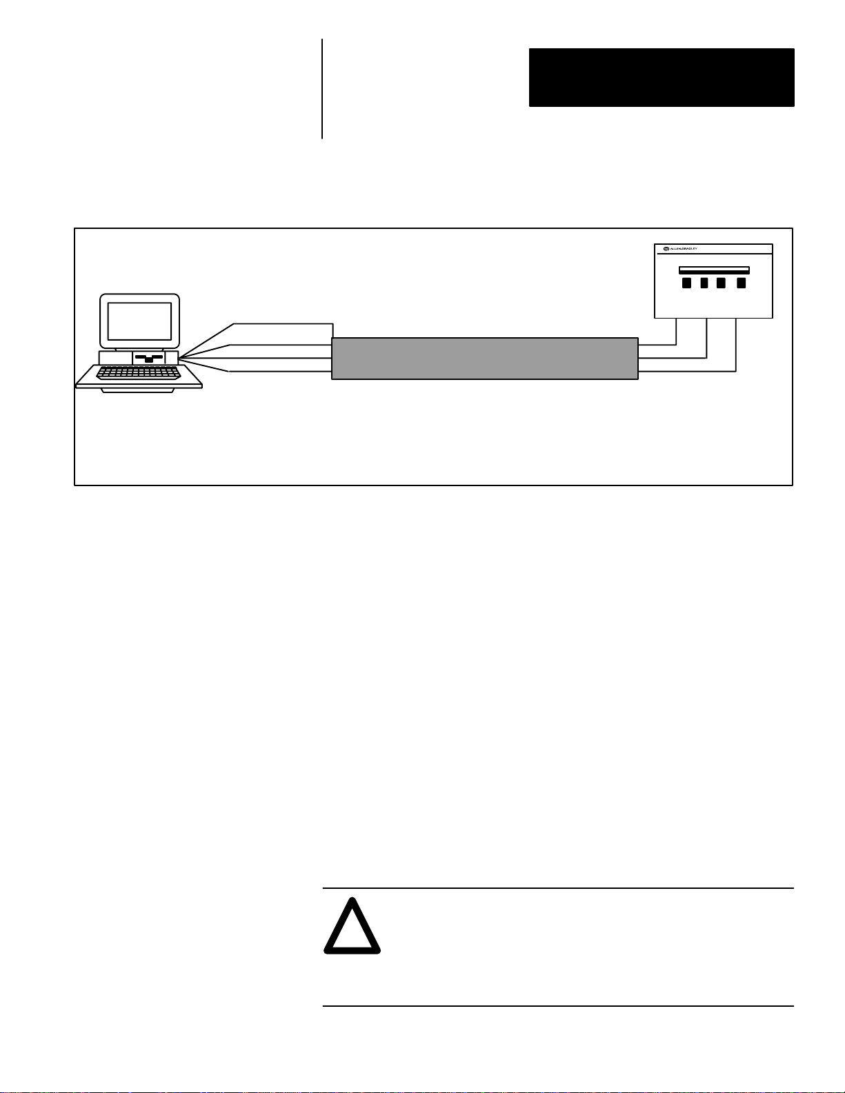
Connection To A Single
Powermonitor Via RS–232C
This section provides the information necessary to connect the computer to a
single Powermonitor via an RS–232C communications link.
To install an RS–232C communications link, both the computer running the
Powermonitor Software and the Powermonitor must be configured for
RS–232C communications.
ATTENTION: Before attempting to connect any
communications cables, confirm that each device is equipped
!
with a Catalog Number 1400 – DCU communication card, and
the port has been configured for RS–232C operation. For
jumper configuration, refer to Publication 1400–5.0
Instruction Sheet.
To implement an RS–232C communications link, a three conductor
RS–232C cable is required between the RS–232C serial port of the computer
and the serial port of the Powermonitor. If you wish to assemble the
RS–232C cable yourself, the cable pin assignments are given below.
Alternatively, pre–assembled RS–232C cables can be ordered from
Allen–Bradley.
To install the RS–232C cable, connect one end of the RS–232C cable to the
desired serial port at the back of the computer running Powermonitor
Software. The three conductors at the other end of the cable are then inserted
into the appropriate communications connection points located on the
Powermonitor. The three connection lines are as follows (refer to Figure 3.1
on Page 3–3.):
3–2
1. Computer DB–25P pin 2 (computer Tx ) connect to the RXD of the
communications card.
2. Computer DB–25P pin 3 (computer Rx ) connect to the TXD of the
communications card.
3. Computer DB–25P pin 7 (computer signal GND) connect to the SG of the
communications card.
Important: The RS–232C communications link described above allows
only one device to be connected to each computer serial port.
Page 17
Chapter 3
Installation
Figure 3.1
Connection to a Single Powermonitor via RS–232C
Important: Note cable
RS–232C
Port
25 Pin (9 Pin)
IBM PC (DTE)
NOTES:
1. RS–232C Cables: 25 pin DB25 or 9 pin DB9, plug (male) or socket (female) depending on mating connector at computer serial port,
50 feet maximum length.
2. If connected directly to data communications equipment (DCE), the Tx and Rx leads need to be reversed at the RS–232C port .
3. A Request To Send signal is required when a modem or a Catalog Number 1400–CC Converter is being used. Connect to T erminal 4 of
the Powermonitor for the RTS signal.
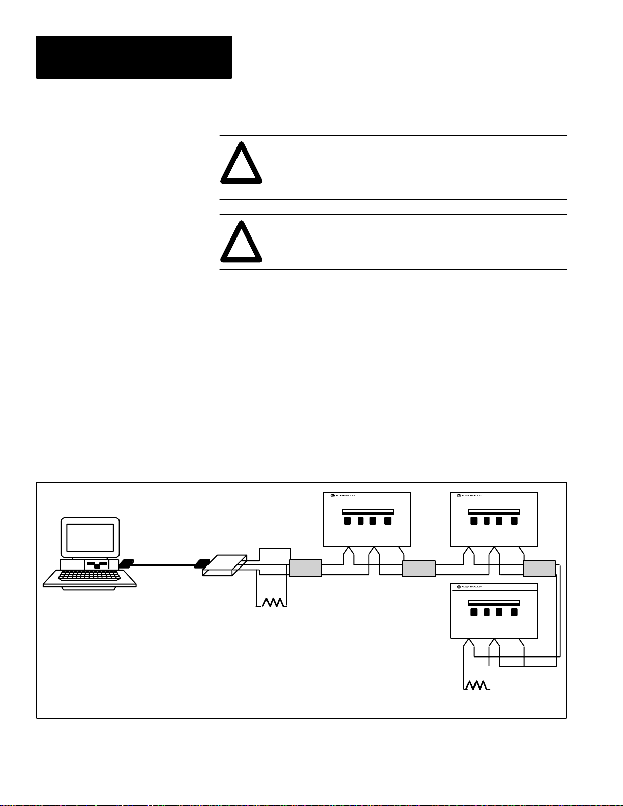
Connection To Multiple
Powermonitors Via RS–485
pin–out numbers
1 (Case Ground)
(2)
3
(3)
2
(5)
7
Bulletin 1400
Powermonitor
TXD RXD SG
SHIELD
RS232C Cable
This section provides the information necessary to connect the computer
running Powermonitor Software to multiple Powermonitors via an RS–485
communications link.
An RS–485 communications link permits many Powermonitors to be
networked together on a two–wire twisted–pair local area network or LAN.
The computer can access information from any one of and up to 32 devices
connected to the RS–485 LAN.
To implement an RS–485 communications link, the computer running the
Powermonitor Software must be equipped with either an internal RS–485
communications card or an RS–232C serial port and an external RS–232C to
RS–485 converter. The Catalog Number 1400–CC converter can be used for
this purpose. Each Powermonitor to be connected to the RS–485 LAN must
be equipped with a Catalog Number 1400–DCU communications card
configured for RS–485. The communications cable required to connect the
computer to each of the Powermonitors consists of a shielded two conductor
twisted pair cable.
ATTENTION: Before connecting any communications cables,
confirm that every Powermonitor is equipped with a RS–485
!
communications port, and the port has been configured for
RS–485 operation. Refer to Publication 1400–800, ‘‘Bulletin
1400 Powermonitor Installation and Operation Manual,” for the
device to determine correct configuration of the port.
3–3
Page 18
Chapter 3
Installation
ATTENTION: Never connect an RS–232C equipped
device to the DATA+ or DATA– lines of an RS–485
!
equipped communication system. Doing so will damage
the RS–485 driver circuits of every device within the site.
ATTENTION: Converters such as the Catalog Number
1400–CC converter must always be used between devices
!
that use RS232C/RS–485 communications standards.
If the computer running the Powermonitor Software uses an RS–232C serial
port in conjunction with an external Catalog Number 1400–CC RS–232C to
RS–485 converter, then install a straight 25–conductor RS–232C cable or a
cable configured with (3) wires to pins 2, 3, and 7 from the desired serial port
at the back of the computer to the RS–232C input on a Catalog Number
1400–CC converter. The DATA+ and DATA– lines on the RS–485 side of
the converter are then connected to the DATA+ and DATA– on each
Powermonitor via a shielded two–wire twisted pair cable as shown in
Figure 3.2.
IBM PC (DTE)
25 Pin
Female
Connector
(DB 25)
RS–232C
Port
RS–232C
Important: Be sure to connect both ends of the shield between devices.
Figure 3.2
RS–485 Communications Connections – External Converter
25 Pin
Male
Connector
(DB 25)
Bulletin 1400–CC
External RS–232C to
RS–485 Converter
SHLD
+
–
150Ω
Resistor
Power–
monitor
#1
SHIELD
Power–
monitor
SHLD SHLD
–
+
To other
devices
#2
SHIELD
Power–
monitor
#3
+
+
150Ω
Resistor
–
SHIELD
SHLD
–
3–4
Page 19
Chapter 3
Installation
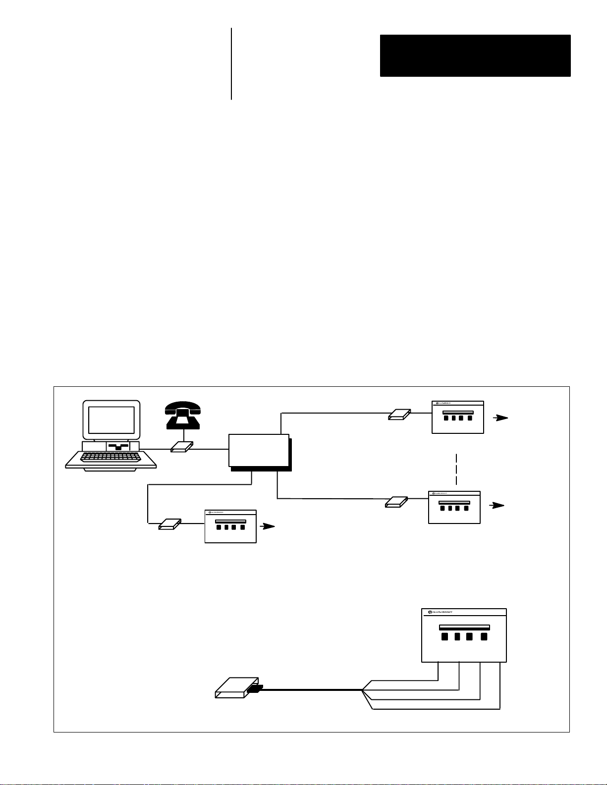
Connection To Single Powermonitor Sites Via The T elephone Network
Telephone
Modem
Site 1
Modem
Line
Telephone
Line
RS–232C
This section provides the information necessary to implement a telephone
modem link between the computer and sites with only single remote
Powermonitors.
Important: The multi–device remote site configuration outlined on page 3–8
should be used if more than one Powermonitor is to be installed at the remote
site in the future, or if a single device at a remote site is located more than 50
feet from the telephone modem.
To implement a telephone modem link, two telephone modems are required.
One modem must be located at the computer and one located at each remote
site requiring a Powermonitor. The single device port at the remote site must
be configured for an RS–232C communications port. The connection
diagram for the modem at the remote site is shown in Figure 3.3. Note that
this configuration (RS–232C) permits only one Powermonitor to be
connected to each modem.
Figure 3.3
Modem Connection to Sites with One Powermonitor
RS–232C
Telephone
Powermonitor
Line
Telephone
Network
Telephone
Line
T o Feeders,
Transducers, or
Pulse Initiations
Requiring
Monitoring
Modem
Site 32
RS–232C
Modem
Site 2
Powermonitor
Transducers, or
Pulse Initiations
Powermonitor
T o Feeders,
Transducers, or
Pulse Initiations
Requiring
Monitoring
T o Feeders,
Requiring
Monitors
Modem
(DCE)
Important: Note cable pin–out numbers
RS232C Cable
Powermonitor
TXD RXD
2
3
7
5
SG
RTS
3–5
Page 20

Chapter 3
Installation
ATTENTION: Before connecting any communications cables,
confirm that the Powermonitor is configured for RS–232C
!
communications and the computer port has been configured for
RS–232C operation. Refer to Publication 1400–800, ‘‘Bulletin
1400 Powermonitor Installation and Operation Manual,” to
determine correct configuration of the port.
The remote site requires a RS–232C cable between the modem and the serial
port of the Powermonitor. If you wish to assemble the RS–232C cable
yourself, the cable pin assignments are given below. Alternatively,
pre–assembled RS–232C cables can be ordered from Allen–Bradley.
Modem Connector DB–25, pin DCU Card Labeled
2 (Rx)
3 (Tx) wire to RXD
7 (signal ground) wire to SG
5 (RTS)
wire to TXD
wire to RTS
1. Modem DB–25S pin 3 (modem Tx ) goes to device RXD.
2. Modem DB–25S pin 7 (modem GND) goes to device GND.
3. Modem DB–25S pin 4 is jumpered to modem DB–25S pin 5.
4. Modem DB–25S pin 6 is jumpered to modem DB–25S pin 20.
To install the RS–232C cable, connect the DB25 connector end of the
RS–232C cable to the serial port at the back of the modem. The four
conductors at the other end of the cable are then connected to the appropriate
communications points located on the Catalog Number 1400–DCU
communications card. The connections are shown in Figure 3.3 on page 3–5.
3–6
Page 21

Chapter 3
Installation
Modem Configuration Information
Modems used with computers running the Powermonitor Software must be
fully Hayes compatible.
If the modems are configured via their communications ports, the
Powermonitor Software will configure them automatically using a set of
default commands. These commands assume that a standard Hayes modem
is being used. If you are using a modem which requires a unique command
set to configure it, refer to Appendix B for instructions on creating a special
MODEM.CFG file for Powermonitor Software to use.
If the modems are configured via hardware DIP switches or a similar
method, configure them to the specifications on next page.
Modems should be configured as follows:
The modem located at the destination site must be configured for
“auto–answer” mode. The modem connected to the computer running the
Powermonitor Software must be configured for “originate” mode.
Both modems must also be configured as follows:
1. Force the RS–232C Data Terminal Ready lead true.
2. Result codes must be sent as numbers.
3. Result codes must be sent by the modem.
4. Echo characters while in command state.
5. Do not force Carrier Detect lead true.
6. Single line connection.
7. Enable modem command recognition.
8. 8 data bits per byte.
9. No parity.
10. 1 stop bit.
The modem must be Hayes compatible. If you are using a sophisticated or
high speed modem, some of the advanced features need to be disabled.
To use a Telebit 3000 modem, disable flow control, disable data compression
and specify CTS operation and delay. Re–configure modem command
register as shown below: (This is an example only.)
AT Z Reset Modem
AT &RO CTS follows RTS
AT S26=1 RTS to CTS Delay Interval
AT S50=6 9600 Baud per second (V.32)
AT S58=O Disable Flow Control
AT S190=O Disable Data Compression
3–7
Page 22
Chapter 3
Installation
Modem Configuration Information Continued
You will need to check the modem’s user’s guide for the codes applicable to,
and appropriate for your modem.
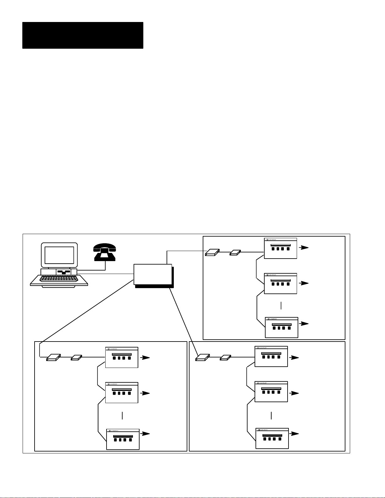
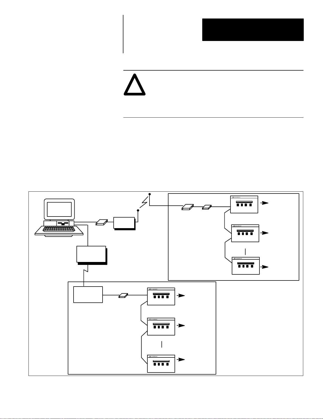
Connection To Multiple Powermonitor Sites Via The T elephone Network
Telephone
Line
IBM PC with Hayes Modem
Telephone
Line
Modem sites having more than one device are similar to sites with one
device except that a Catalog Number 1400–CC RS–232C to RS–485
converter must be used and the Powermonitor communications card must be
configured for RS–485 communications.
The connection diagram for this configuration is shown in Figure 3.4.
Telephone modems must be configured in the manner described on Page 3–7.
Figure 3.4
Modem Connection to Sites with One or More Powermonitors
Telephone
Network
Telephone
Line
Telephone
Line
RS–232C
Modem
Site 3
Catalog
Number
1400-CC
RS–485
RS–485
Powermonitor #1
T o Feeders,
Transducers, or
Pulse Initiations
Powermonitor #2
Powermonitor #32
3–8
Modem
Site 1
RS–232C
Catalog
Number
1400-CC
Modem
RS–232C
Catalog
Number
1400-CC
RS–485
RS–485
Powermonitor #1
T o Feeders,
RS–485 RS–485
Powermonitor #2
Powermonitor #32
Transducers, or
Pulse Initiations
Site 2
Powermonitor #1
T o Feeders,
Transducers, or
Pulse Initiations
Powermonitor #2
Powermonitor #32
Page 23
Chapter 3
Installation
ATTENTION: Special high level isolation is required between
units when the possibility of high ground potential differences
!
exist. This may occur when separate grounds are used, or when
communicating to a unit off of the power ground matt. Failure to
do so can lead to personal injury or death, property damage, or
economic loss.
Important: For each site, total RS–485 cable length (Maximum 4,000–ft.)
between all devices in the RS–485 network when using 22 gauge shielded
twisted pair.
Connection To Remote Sites Using Other Methods of Communications
IBM PC with Hayes Modem
Fiber Optic
Converter to
RS–232C Output
Fiber Optic
Link
Fiber Optic
Converter to
RS–232C Output
Additional methods of connecting the computer running Powermonitor
Software to Powermonitor sites include fiber optic, radio, and microwave
links. See Figure 3.5.
Figure 3.5
Connection to Remote Sites using Other Methods of Communications
Radio
TX/RX
RS–232C
Catalog
Number
1400-CC
RS–232C
Modem
Site 2
RS–485
Powermonitor #1
Catalog
Number
1400-CC
RS–485
Powermonitor #1
Powermonitor #2
Powermonitor #32
T o Feeders,
Transducers, or
Pulse Initiations
Site 1
T o Feeders,
Transducers, or
Pulse Initiations
Powermonitor #2
Powermonitor #32
Contact the Allen–Bradley Support Division for information regarding
remote links using any of the above methods or any methods not shown.
3–9
Page 24

Chapter 3
Installation
Installation Of The System Software
Creating A Backup Copy of the Powermonitor Software
Contents of the Powermonitor Software Package
Upon receipt of the Powermonitor Software software package, it is important
to check its contents to ensure that you have received the necessary items.
Your package should contain:
1. Publication 1400–801 ‘‘Powermonitor Software Installation and
Operation Manual.”
2. The Powermonitor Software diskettes(Double Sided, Double Density in
sizes 3–1/2 and 5–1/4 inches)
Should any of the above items be missing, contact Allen–Bradley
immediately and report the missing items.
Before using the Powermonitor Software, create a backup of the software by
copying the entire contents of the Powermonitor Software diskette onto
backup diskette. Store the original diskette in a safe place and use only the
backup copy to run the Powermonitor Software.
3–10
Page 25

Chapter 3
Installation
Installing The Software Onto A Hard Drive
The Powermonitor Software is designed to run either from the floppy disk it
comes on, or from a hard disk drive, onto which it can be copied.
If you wish to run the Powermonitor Software from the floppy disk, proceed
to Chapter 4 for instructions on starting and running the Powermonitor
Software.
If you wish to run the Powermonitor Software from the hard drive of your
computer, first perform the following steps to install the Powermonitor
Software onto the hard drive:
1. Create a directory called SP on your hard disk. You may select any drive
to create the directory on (C:, D:, etc.). The following instruction set
creates the directory on the C: drive:
C: <Enter>
MD SP <Enter>
2. Insert the Powermonitor Software program diskette into the A: drive of
your computer and copy the entire contents of the disk into the SP
directory on your hard disk. The following instruction assumes that the
SP directory was created on your C: drive. If this is not the case, replace
C: with the appropriate drive designation.
COPY A:*.* C:\SP <Enter>
3. Check that the SP directory on your hard disk contains the following files:
SP.EXE
SP.EXE is the Powermonitor Software program.
PASSWORD.CFG
Password.CFG is the Powermonitor Software password and setup file.
This file must be present to allow any protected functions to be performed
such as: changes to Powermonitor parameters, or relay control
commands. This file also allows communications setups to be saved.
Chapter 4 describes this in more detail.
The Powermonitor Software has now been installed on your hard disk. Refer
to Chapter 4 for instructions on starting up and using the Powermonitor
Software program.
3–11
Page 26

Chapter 3
Installation
3–12
Page 27

Chapter
Chapter Objectives
Startup
A–B
4
Using The Software
This chapter provides general instructions on starting the Powermonitor
Software, establishing communications with a remote device, using the
Powermonitor Software menu system, and using the on–screen help feature.
To Run The Software From The Hard Drive
If the user has performed the hard drive installation procedure given in
Chapter 3, the Powermonitor Software may be run from the hard drive by
entering the following commands:
CD \SP <Enter>
SP <Enter>
After a moment, the Powermonitor Software TITLE screen will appear on
the monitor (see Figure 4.1 on Page 4–2), followed by the Powermonitor
Software CONNECTION SCREEN.
To Run The Software From The Floppy Diskette
ATTENTION: The floppy diskette used to run the Powermonitor
Software must not be write protected, since the Powermonitor
!
Software saves the last CONNECTION screen data entered by
the user, and the Powermonitor Software PASSWORD to the
currently selected drive when the user exits to DOS.
If the user wishes to run the Powermonitor Software from the floppy
diskette, enter the following commands:
A: <Enter>
SP <Enter>
After a moment, the TITLE screen will appear on the computer monitor
(see Figure 4.1 on Page 4–2), followed by the CONNECTION SCREEN.
4–1
Page 28

Chapter 4
Using The Software
Figure 4.1
Powermonitor Software Title Screen
VERSION: 1.0
COPYRIGHT 1993
Possible Errors On Startup
Establishing Connection With A Remote Device
If difficulty is experienced when starting the Powermonitor Software
program, re–check each of the steps on Page 3–8 through 3–10 and Page 4–1
to ensure they have been performed correctly. Check the help screen for
other suggestions. If difficulties persist, contact Allen–Bradley for assistance.
Connection Screen
The CONNECTION SCREEN (See Figure 4.2 on Page 4–3), which appears
following the TITLE screen on power–up, is used to establish
communications between the computer and a Powermonitor.
4–2
Page 29

Figure 4.2
Connection Screen
Chapter 4
Using The Software
At any time the CONNECT STATUS may be verified by pressing F6, which
presents the CONNECTION SCREEN. This CONNECTION SCREEN may
be displayed at any time by returning to the MAIN MENU (by pressing the
Esc key), positioning the cursor onto the CONNECT option and pressing the
<Enter> key. The user may, alternately, press F6 to directly display this
screen.
Establishing Communications
The user is required to enter information into six data fields prior to
establishing communications (ie. connecting) to a Powermonitor.
The flashing data field indicates the present cursor position. The arrow keys
are used to move the cursor to the data entry fields on the CONNECTION
screen. A help line at the bottom of the screen indicates the options available
for each field.
The following fields on the CONNECTION screen require information to be
entered by the operator prior to connecting with the device.
a. SITE ID. This field is used to assign a name to the location of the
Powermonitor which is to be accessed. The name used here will
appear on each data screen accessed.
To change the SITE ID field, position the cursor onto the field, type
any alphanumeric site name (up to 10 characters) and press the
<Enter> key. This field now becomes a label used on other
screens.
b. UNIT ID. This field specifies which Powermonitor to address and
establish communications with.
4–3
Page 30

Chapter 4
Using The Software
Each Powermonitor has its own unique 4 digit UNIT ID (Address)
that can be viewed or changed from the device’s front panel. Each
Powermonitor should initially have an address. Enter the number
into the UNIT ID field of the device whose data you wish to
display. The UNIT ID must be set before communications can be
established with that device.
To change the UNIT ID field, position the cursor, enter a four digit
number and press the <ENTER> key. The devices’ default number
is assigned at the factory and inked on the back of the device.
c. COMM PORT. This field identifies which of the computer’s
serial ports is connected to the remote device. Position the cursor
onto the PORT field and press the plus or minus (“+” or “–”) keys
to select the serial port which will be used for communication to
that site (COM1 or COM2).
d. BAUD RATE. Position the cursor onto the BAUD field and press
the plus or minus keys to select the baud rate of the serial port. The
Powermonitor Software supports 300, 1200, 2400, 4800, 9600, and
19.2K baud rates.
Important: When setting the BAUD RATE parameter, the system operator
must ensure that all modems and devices connected to the assigned serial
port have also been configured to operate at the same baud rate.
e. DIAL (PHONE #). This field is used only when the
Powermonitor Software is communicating with a remote device via
telephone modems. To change this parameter field, type the
telephone number of the destination site and press <Enter>.
Examples of valid formats for telephone number are:
123–4567 Regular seven digit number.
1–414–382–2000 Number with long distance prefix and area
code.
14143822000 Numbers can be entered without dashes
(using no spaces).
9,382–2000 Commas can be used to insert a time delay
(approx. 3 sec.) between the dialing of digits.
f. LINE TYPE. This field determines the type of connection to be
established between the Powermonitor Software and the remote
device. Pressing the plus (+) or minus (–) keys will select the
LINE TYPE. There are three valid line types:
• DIRECT CONNECT. If the site is connected to the computer
via a dedicated RS–232C or RS–485 communication link, then
choose the DIRECT CONNECT option.
4–4
Page 31

Chapter 4
Using The Software
If the site is only accessible via the telephone network using a
modem, then choose either the TOUCH (touch–tone) or PULSE
line type option, depending on the type of phone line dialing
system being used.
• MODEM (TOUCH TONE). Used when the computer is
connected to a remote device via a TOUCH TONE telephone
modem.
• MODEM (PULSE). Used when the computer is connected to a
remote device via a PULSE telephone modem.
Important: If either MODEM option is selected, the Powermonitor Software
will configure the connected modem using a set of default commands.
These commands assume that a standard Hayes modem is being used.
If you are using a modem which requires a different command set to
configure it, refer to Appendix B for instructions on creating a special
MODEM.CFG file for the Powermonitor Software to use.
Connecting With The Remote Device
Once the six data fields described above have been configured, the
CONNECT OPTION field is used to invoke the connection procedure. When
invoked, the Powermonitor Software will attempt to establish
communications with the remote device specified in the UNIT ID field.
To initiate the connection procedure, position the cursor over the CONNECT
OPTION field and press the <Enter> key.
The present CONNECT STATUS field will indicate if a connection to the
device was successful. The following status messages will be indicated in
the present CONNECT STATUS field, depending on the present status of
communications:
1. Connecting Directly. When using the DIRECT CONNECT line type,
the Powermonitor Software will display the message:
ATTEMPTING CONNECTION ...
When the Powermonitor Software establishes communication with the
specified unit, the CONNECT STATUS field will display:
DIRECT CONNECTION ESTABLISHED
and the entry in the CONNECT OPTION field will change to:
DISCONNECT
to allow disconnection, if desired.
4–5
Page 32

Chapter 4
Using The Software
When connection cannot be made, the Powermonitor Software will
display:
UNIT NOT RESPONDING
If this occurs, there is a problem that is preventing communications from
being established. Determine and correct the problem and retry
connection by pressing the <Enter> key again while on the flashing
CONNECT OPTION field. Chapter 8 provides troubleshooting
information in case of difficulty.
2. Connecting via Telephone Modem. When using either of the two
modem line types, the Powermonitor Software will display the message:
DIALING
while dialing the telephone number entered in the DIAL (PHONE #)
field.
When the Powermonitor Software establishes communication with the
destination site, the Powermonitor Software will display:
MODEM CONNECTED ... Unit responding.
and the CONNECT OPTION will change to:
DISCONNECT
to allow disconnection, if desired.
If a connection cannot be made, then one of the following messages will
be displayed:
MODEM CONNECTED ... Unit not
responding.
MODEM NOT RESPONDING
NO CARRIER PRESENT
LINE BUSY
COMMAND ABORTED
MODEM ERROR
Pressing the ESC key will abort the dialing process and the following
message will be displayed:
4–6
CONNECTION ABORTED
Chapter 8 lists possible causes for the above difficulties.
Page 33

Chapter 4
Using The Software
The Menu System
The Powermonitor Software is an easy–to–learn and simple–to–use software
package incorporating a very powerful menu–driven operator interface. The
MAIN MENU is illustrated in Figure 4.3. This menu can be displayed at any
time by pressing the <Esc> key.
Figure 4.3
Main Menu Screen
Important: The Powermonitor Software MAIN MENU will not be made
available to the operator if the PASSWORD.CFG file is missing from the SP
directory on disk. Instead, the operator may only use the function keys F1 to
F6 to connect with Powermonitors and view device data. The <Esc> key, in
this case, is used to escape to DOS.
Any screen or function option can be accessed by using the arrow (cursor)
keys. To select the option, position the highlighted cursor over the desired
name, then press the <Enter> key. Each time a menu item is selected, the
information requested will be displayed or the selected function will be
performed.
After selecting a menu option, the system operator can always return to the
MAIN MENU by pressing the <Esc> key.
ATTENTION: Device time and date must be set when
communication is first established and whenever the device
!
loses power.
4–7
Page 34

Chapter 4
Using The Software
Help/Message Line
The Powermonitor Software system provides a HELP/MESSAGE line at the
bottom of every screen, which serves two important purposes:
a. While any menu or screen is being displayed, a HELP line is
shown at the bottom indicating which keyboard keys are active on
the present screen. (Note: A quick keyboard reference for the
Powermonitor Software system is also given in Appendix D).
b. A MESSAGE line is used to display system status messages to the
operator. Examples of system status messages include password
prompts, modem connection status messages and system error
messages.
Screens And Functions
The Powermonitor Software automatically determines which type of remote
device it is communicating with, and configures the MAIN MENU
accordingly to provide the options specific to that device.
The MAIN MENU screen provides access to all of the Powermonitor
Software’s remote device data display and configuration screens and
functions, as well as the on–line HELP and the Powermonitor Software
PASSWORD screens.
Remote device data screens include:
a. REAL–TIME. Displays the real–time data being measured or
monitored by the remote device.
b. EVENT LOG. Up load and display the remote device’s Event Log.
c. SNAPSHOT LOG. Up load and display the remote device’s
on–board Snapshot Log.
d. STATUS LOG. Displays the present condition of the remote
device’s three on–board control relays and four status inputs.
e. MIN/MAX LOG. Up load and display the remote device’s
on–board Min/Max Log.
Remote device configuration screens include:
a. DEVICE SETUP. Allows the operator to remotely configure the
operating parameters of the device.
b. SETPOINT/RELAY SETUP. Allows the operator to configure the
setpoint parameters of the remote device.
c. CLEAR FUNCTIONS. A number of different functions are
provided for the purpose of clearing or resetting Min/Max Log
values, kWH, kVARH and kVAH totals, status input counters, etc.
4–8
Page 35

Chapter 4
Using The Software
Screens And Functions Continued
Other device functions include:
a. OPERATE RELAY. Allows the operate to manually control the
on–board relays of the remote device.
b. CONNECT. Selects the CONNECTION screen to enable the
operator to select another Powermonitor to communicate with.
c. MAIN MENU, CLEAR HOURS: After entering this menu
selection and successfully entering the SP software password, the
prompt“CLEAR ALL HRS,kWH,kVARH, OR kVAH–(0/1/2/3)?”
will be displayed. By entering the value of 0, this will clear the
kWH, kVARH and kVAH counters simultaneously. NOTE: The
kVAH option is displayed and cleared for those powermonitor units
with firmware version 0.7. or later.
Shortcut Keys
The Powermonitor Software provides a shortcut method for directly selecting
any of the five frequently used primary data screens, and the CONNECTION
screen. The following function keys can be used to quickly select screens:
Password
F1 REAL–TIME screen
F2 EVENT screen
F3 SNAPSHOT LOG screen
F4 STATUS screen
F5 MIN/MAX LOG screen
F6 CONNECTION screen
Screen Descriptions
Detailed descriptions of each remote device data and configuration screen
can be found in Chapter 5, ‘‘Powermonitor Data Display and Configuration.”
The Powermonitor Software provides a security system to protect
Powermonitors from inadvertently:
a. having their relays manually operated/released.
b. having their kWH, kVARH or kVAH totals cleared, or Min/Max
Logs reset.
c. having any of their user–programmable operating parameters reset
from the computer.
The Powermonitor Software password is used for this purpose. Prior to any
of the above listed operations, the Powermonitor Software will prompt the
user for the required password. If the password entered by the operator is
incorrect, the Powermonitor Software will abort the operation.
When the Powermonitor Software is run for the first time, the Powermonitor
Software password is set to the single digit zero (“0”). It is recommended
that the user change this default password as soon as possible, using the
Powermonitor Software PASSWORD screen (see Figure 4.4 on Page 4–10).
4–9
Page 36

Chapter 4
Using The Software
Important: The Powermonitor Software password is not the unit password.
Figure 4.4
Powermonitor Software Software Password Screen
To change the Powermonitor Software password, return to the MAIN MENU
by pressing the <Esc> key, position the cursor onto the CHANGE
PASSWORD option and press the <Enter> key.
The Powermonitor Software prompts the user to enter the present password.
When this password has been correctly entered, the user is asked to enter the
new password and then asked to re–enter the new password again for
confirmation. The password can be any alphanumeric string up to 20
characters in length. Blanks are not permitted.
If the attempt to change the Powermonitor Software password is successful,
the following message will be displayed:
PASSWORD
HAS BEEN UPDATED
If the attempt to change the Powermonitor Software password is not
successful, the following message will be displayed:
PASSWORD
HAS NOT CHANGED
On completion of the CHANGE PASSWORD function, the MAIN MENU
will be displayed.
4–10
Page 37

Chapter 4
Using The Software
On–Line Help
Update Unit Time
The Powermonitor Software provides an on–screen HELP feature which can
provide the operator with information about communication, modem usage,
and technical support, without having to refer back to Publication 1400–800,
‘‘Bulletin 1400 Powermonitor Installation and Operation.”Help is also
available from the connection screen, when not connected by pressing H.
To access the HELP INFORMATION SCREEN, select the HELP option
from the MAIN MENU.
The MAIN MENU provides a utility to update the time of a Powermonitor.
This function sets the on–board clock of the remote device to the value of the
computer’s internal clock. A remote device’s present time setting can be
viewed by simply displaying the REAL–TIME or STATUS screen for that
device. Time is displayed in the bottom right–hand corner for each of these
screens. While the Main Menu is displayed, press the F8 key to change the
unit time to the computers present system time. F8 – Update Unit Time. This
function is now password protected and displays the current PC Time to
allow the user to see what would be sent to each unit prior to sending the
time.
4–11
Page 38

Chapter 4
Using The Software
Exit To DOS
To exit from the Powermonitor Software program and return to DOS, the
operator must use the EXIT TO DOS option on the MAIN MENU screen:
1. Return to the MAIN MENU from any other screen by pressing the <Esc>
key.
2. Position the cursor over the EXIT TO DOS option using the arrow keys,
or by pressing the <Esc> key again.
3. Press the <Enter> key.
The operator will be immediately returned to DOS.
Connection Configuration Save Feature
Immediately prior to the operator being returned to DOS, the Powermonitor
Software will save the last information entered in the CONNECTION screen
(SITE ID, UNIT ID, COMM PORT, etc.) to a disk file.
When the Powermonitor Software is started again later, the previous
connection configuration will be loaded into the CONNECTION screen
automatically. This means the operator will not be required to re–enter data
in the CONNECTION screen fields, if connection to the same remote device
is desired. The operator need only position the cursor on the CONNECT
OPTION field and press <Enter> to reconnect to that device.
Important: The Powermonitor Software saves the connection setup to the
file in the SP disk directory named PASSWORD.CFG, which is the same file
containing the Powermonitor Software password. If this file is missing from
the SP directory, the Powermonitor Software will always display the default
communications options in the CONNECTION screen when the program is
first started.
4–12
Page 39

Chapter
Chapter Objectives
Displaying Single Device Data
A–B
5
Powermonitor Data Display And Configuration
This chapter describes the steps necessary to display real–time and logged
data from a Powermonitor, and how to configure the operating parameters of
the device.
Data Display Formats
Following connection to a Powermonitor (as described in Chapter 4) the
system operator can display data from that device by selecting the desired
data screen from the MAIN MENU. These include:
a. REAL–TIME
b. EVENT LOG
c. SNAPSHOT
d. STATUS (incl. Relay Status, Status Inputs, and Setpoint Status)
e. MIN/MAX
Displaying Device Data
To display data from a particular device:
1. Connect with the Powermonitor as described in Chapter 4 (if not
previously performed).
2. Return to the MAIN MENU by pressing <Esc>, select the desired data
screen using the cursor keys, and press <Enter>.
Alternately, the operator can use the shortcut keys to view data screens
directly, rather than using the MAIN MENU. Shortcut key functions are
listed in the HELP line at the bottom of the screen.
The most recent data for the selected device screen should appear almost
immediately.
Important: If the site is accessed via a modem that is not presently
connected, a series of messages will appear at the bottom of the screen
indicating modem connection status. It may take 30 seconds to establish
connection with the site before updated data will appear on the
Powermonitor.
5–1
Page 40

Chapter 5
Powermonitor Data Display and Configuration
Important: An audible alarm (beep) will be encountered if a
communications failure occurs when attempting to display any device screen.
In this case, the operator should verify communication with the device by
entering the CONNECTION screen and checking that the CONNECT
STATUS field is reading CONNECTED. If this is not the case, attempt to
reconnect with the device as described in Chapter 4, ‘‘Using The Software.”
If connection cannot be accomplished, refer to Chapter 8,‘‘Troubleshooting.”
An example of a typical device data screen is provided in Figure 5.1.
Figure 5.1
Example of Powermonitor Data Screen
5–2
At the bottom of each data screen the UNIT ID indicates from which unit
data is presently being monitored. The DATE and TIME shown at the
bottom of some screens (ex. REAL–TIME and STATUS screens) indicates
the time at which the data was last updated.
The data shown on each screen will be continually updated as long as the
device is connected. The rate at which data is refreshed will depend upon the
baud rate of the communications link.
Displaying Additional Data
In the case of screens which contain too much information to be shown at
once, such as the SNAPSHOT LOG, the up/down arrow or PgUp/PgDn keys
can be used to scroll or page up/down through the data, respectively. The
left/right arrow keys can also be used to select any available adjacent screens
(ex. SNAPSHOT Left, Center, Right).
Page 41

Chapter 5
Powermonitor Data Display and Configuration
If additional data is available, a message line at the bottom of the data screen
will tell the operator which key functions to use to view the data.
To Exit From Any Data Display Screen
To exit from any screen, the operator can either press the <Esc> key to return
to the MAIN MENU, or press one of the shortcut keys to display another
data screen directly.
Configuring Powermonitors
The Powermonitor Software gives the system operator the ability to remotely
view or reconfigure the DEVICE SETUP and SETPOINT/RELAY SETUP
parameters of a Powermonitor from the Master Display Station.
Displaying The Setup Or Setpoint Parameters Of Any Devices
All device configuration functions are accessed from the MAIN MENU. To
display data from a particular device:
1. Connect with the desired Powermonitor as described in Chapter 4.
2. Return to the MAIN MENU.
3. Place the cursor onto the DEVICE SETUP or SETPOINT/RELAY
SETUP field for the desired device (depending on which set of
parameters you wish to view and/or configure) and press the <Enter> key.
An example of a Powermonitor configuration screen is provided in
Figure 5.2.
Figure 5.2
Example of Powermonitor Configuration Screen
5–3
Page 42

Chapter 5
Powermonitor Data Display and Configuration
Important: Communication alarm conditions that were described for
displaying device data screens also apply to displaying configuration screens.
Important: Device configuration screens are not available to the operator if
the PASSWORD.CFG file is missing from the SP directory on disk.
Modifying Parameter Values
In the device configuration screens, the Powermonitor Software will prompt
the operator to enter the Powermonitor Software password. This is necessary
before any device parameters may be modified.
When working in the device configuration screens, the arrow keys are used
to position the cursor onto the desired parameter field. The cursor position is
indicated by a flashing parameter value.
Some parameter fields are changed by entering a numerical value. If an
attempt is made to set a parameter to a value outside its allowable limits, the
value is rejected. Should a value be rejected, the user must re–enter with a
proper value. The operator may also cancel the entry of any value by
pressing the <Esc> key.
Some parameter fields are changed by pressing the plus or minus keys which
cause the field to increment/decrement through a pre–defined range of
values, or number of parameter selections. This is indicated by +/– toggle
UP/DN appearing in the lower right hand portion of the screen.
Reconfiguring The Device With The New Parameter Values
The Powermonitor will be reconfigured using the new values entered into the
screen when the operator presses the <Esc> key to return to the MAIN
MENU. The <Esc> key, in this case, is used as a SAVE & EXIT command.
After transmitting the changes and returning to the MAIN MENU, it is
recommended that the operator redisplays the setup screen for that device to
verify that the new parameter values have, in fact, been implemented.
5–4
Page 43

Chapter 5
Powermonitor Data Display and Configuration
Data Display and Configuration Screens
Data display screens for the Powermonitor include:
REAL–TIME
EVENT LOG
SNAPSHOT
STATUS
MIN/MAX
Configuration screens for the Powermonitor Software include:
DEVICE SETUP
SETPOINT/RELAY SETUP
Additional device functions include:
CLEAR kWH
CLEAR kVAH
CLEAR kVARH
CLEAR S1 COUNTER
CLEAR MIN/MAX
CHANGE PASSWORD
All device data display screens, configuration screens and functions can be
accessed via the MAIN MENU.
Main Menu
For the Powermonitor, the operator must first select the CLEAR HOURS
option to access the CLEAR kWH, CLEAR kVARH, or kVAH functions for
the Powermonitor (Refer to Figure 5.3 on Page 5–5). The Powermonitor
Software will then prompt the operator for the password and then to specify
which total is to be cleared. After entering this menu selection and
successfully entering the SP software password, the prompt “ CLEAR ALL
HRS, kWH, kVARH, OR kVAH– (0/1/2/3) ?” will be displayed. By entering
the value of 0, this will clear the kWH, kVARH, and kVAH counters
simultaneously. NOTE: The kVAH option is displayed and cleared for only
those powermonitor units with firmware version 0.7 or later. The Main Menu
screen also provides an additional CLEAR S1 COUNTER function.
The RELAY CONTROL option of the MAIN MENU is described in
Chapter 6, ‘‘Manual Control of Powermonitor Internal Relays.”
5–5
Page 44

Chapter 5
Powermonitor Data Display and Configuration
Figure 5.3
Main Menu Screen
Real Time Data
The REAL–TIME screen for the Powermonitor displays the present
real–time readings of all values monitored by the device (see Figure 5.4). A
complete description of the parameters shown on the REAL–TIME screen is
given in Publication 1400–800, ‘‘Bulletin 1400 Powermonitor Installation
and Operation Manual.”
Figure 5.4
Real–Time Data Screen
5–6
The DATE and TIME at the bottom of the screen indicate the time at which
the displayed data was last updated.
Page 45

Chapter 5
Powermonitor Data Display and Configuration
Event Log
The Powermonitor contains a record of events that is stored within its
internal nonvolatile memory. An event is defined as any alarm condition,
over/under limit condition, status input change, or relay operation. Also
included as events are changes in the device setup parameters and device
power–ups.
Figure 5.5
Event Log Screen
The EVENT LOG screen displays the record of device events that has been
up loaded by the Powermonitor Software system (see Figure 5.5).
Information is divided into six columns:
1. EVENT. This column describes the type of event that has occurred.
Examples of typical events include the occurrence of a device power–up,
a change in the device set–up parameters, setpoint alarms, a change in any
of the device’s four status inputs, and events that cause changes in any of
the three control output relays.
2. STATE. This column gives the current state of any alarms resulting
from the occurrence of an event. Examples of typical state messages
include the state of the alarm (ACTIVE or NORMAL) along with a relay
number if one is associated with the setpoint alarm. The manual
operation and release of relays is also indicated here.
3. VALUE. This column is reserved for numerical information that is
related to the event. Examples include parameter values that are
associated with the triggering of any setpoint alarm event.
4. RELAY. This column shows the state of the three on–board device relays
(R1, R2, and R3, respectively) immediately following the event (ON =
operated, OFF = released). Please note that the state of the relays may not
be associated with the occurrence of every event.
5. DATE. This column gives the date that the event occurred.
6. TIME. This column gives the date and time that the event occurred.
5–7
Page 46
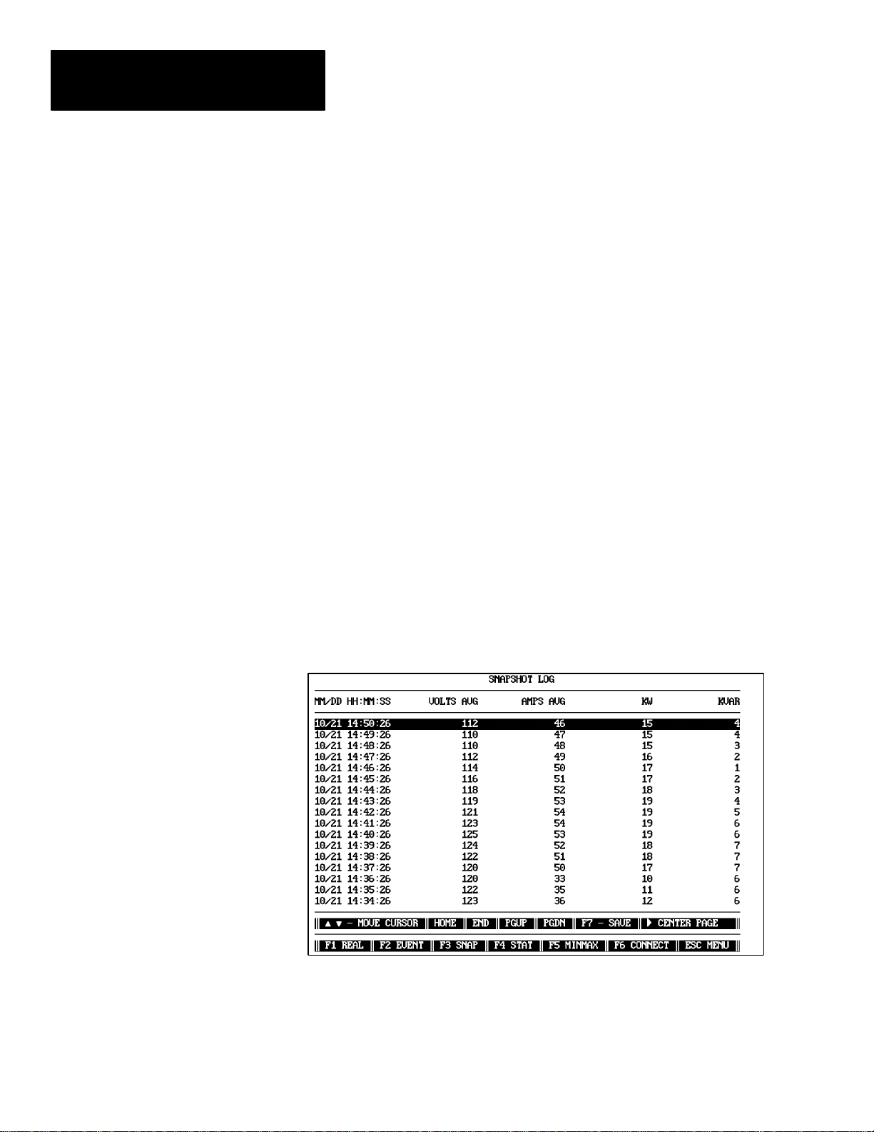
Chapter 5
Powermonitor Data Display and Configuration
Viewing of the entire log is accomplished by moving the highlight bar with
the arrow keys, the Page Up or Page Down keys, or the Home or End keys.
Save Disk
Pressing the F7 key while displaying the EVENT LOG will save the present
contents of the log to a disk file in the present directory. The log file can
then be printed out as described in Chapter 7.
Snapshot Log
The Powermonitor implements a snapshot log that allows the device to store
the historic values of Volts, Amps, kW, kVAR, kW Demand, Amp Demand,
Power Factor, Vaux, Frequency, kWH, kVARH, and kWH Reverse at
user–defined intervals ranging from 1 second to 400 days.
The SNAPSHOT LOG screen displays a record of device snapshots that
have been up loaded by the Powermonitor Software. Since there is a large
amount of information to display, the snapshot information is divided and
displayed on three screens: left, center, and right. Examples of the three
SNAPSHOT LOG screens are shown in Figure 5.6 through Figure 5.8.
Figure 5.6
Snapshot Log (Left) Screen
5–8
Page 47

Figure 5.7
Snapshot Log (Center) Screen
Chapter 5
Powermonitor Data Display and Configuration
Figure 5.8
Snapshot Log (Right) Screen
Save
Pressing the F7 key while displaying the SNAPSHOT LOG will save the
present contents of the log to a disk file in the present directory. The log file
can then be printed out as described in Chapter 7, ‘‘Printing Log Disk Files.”
5–9
Page 48

Chapter 5
Powermonitor Data Display and Configuration
Important: Power Factor leading is represented as an unsigned value.
Power Factor lagging is represented as a negative value. The kWH and
kVARH values represent TOTAL values (sum of import and export). The
kWH REVERSE value represents kW exported.
Status Data
The STATUS screen (Figure 5.9) displays and monitors the present state of
the three Powermonitor control relays, four status inputs, and any of
setpoints or alarms that are in an active condition. A description of the data
shown on the STATUS screen is given below.
Figure 5.9
Status Screen
5–10
Relay
This portion of the STATUS screen shows the present condition of the three
relays.
1. OFF. A relay is considered to be OFF when its normally–open contacts
are open (for Relay #1 this is R14/R11) and normally–closed contacts are
closed (R11/R12). This state occurs when the relay is not assigned to any
setpoint, or when the assigned setpoint is not in an active condition.
2. ON. A relay is considered to be ON when it has been activated by a
setpoint. In this state, the normally–open contacts have been closed and
the normally–closed contacts have been opened. This state occurs when
a relay has been assigned to a setpoint and the setpoint parameter value is
outside the bounds of its low or high limits.
Page 49

Chapter 5
Powermonitor Data Display and Configuration
3. FORCED OFF. A relay is considered to be forced off when it has been
manually released by the operator from the keyboard. All device relays
can be manually released from the RELAY CONTROL section of the
STATUS screen.
4. FORCED ON. A relay is considered to be forced on when it has been
manually operated by the operator from the Main Menu. All relays can
be manually operated from the RELAY CONTROL section of the
STATUS screen.
Status Input
This portion of the STATUS screen displays the condition of the
Powermonitor’s four status inputs.
1. OFF. This state indicates that the voltage present at the Status Input
terminal is less than the INACTIVE voltage as specified in the
Publication 1400–800 ‘‘Bulletin 1400 Powermonitor Installation and
Operation Manual.”
2. ON. This state indicates that the voltage present at the Status Input
terminal is greater than the ACTIVE voltage as specified in the
Publication 1400–800 ‘‘Bulletin 1400 Powermonitor Installation and
Operation Manual.”
Count
This parameter displays the number of pulses (contact transfers) that have
been accumulated on the device’s Status Input #1 since the last time the
counter was cleared.
Active Alarms
This portion of the STATUS screen displays:
1. All of the user specified setpoints that are presently active. All 17
setpoints (if active) will be displayed in this area of the STATUS screen.
2. All other alarm conditions detected by the Powermonitor
(self–diagnostics failures, etc.).
Date and Time
The DATE and TIME at the bottom of the screen indicate the time at which
the displayed data was last updated. This is the time as read from the device.
5–11
Page 50

Chapter 5
Powermonitor Data Display and Configuration
MIN/MAX Log
The MIN/MAX LOG screen displays the contents of the Powermonitor
internal Min/Max Log that has been up loaded. This log contains the
recorded extreme values for the power parameters (see Figure 5.10).
Pressing F7 function key will save the displayed MIN/MAX data to the disk,
even though F7 SAVE does not appear on the screen.
Figure 5.10
Min/Max Log Screen
5–12
Page 51

Chapter 5
Powermonitor Data Display and Configuration
Device Setup
The screen shown in Figure 5.11 is displayed when the operator selects
DEVICE SETUP for a Powermonitor. To modify any parameter values, the
Powermonitor Software password must be entered, followed by <Enter>.
Pressing <Esc> will return to the MAIN MENU.
Figure 5.11
Device Setup Screen
Setup Parameter Descriptions
A brief description of each parameter accessible from the DEVICE SETUP
screen is given below. For more information, refer to Publication 1400–800
‘‘Bulletin 1400 Powermonitor Installation and Operation Manual.”
5–13
Page 52

Chapter 5
Powermonitor Data Display and Configuration
a. UNIT I.D. This is the device’s 4–digit identification number, used
for communications with the Powermonitor Software. Range of
possible values is 1 to 9999.
b. BAUD RATE. This is the baud rate for the RS232/485
communications with the device.
c. VOLTS SCALE, AMPS SCALE, Vaux SCALE, and I4 SCALE.
Refer to the Publication 1400–800, ‘‘Bulletin 1400 Powermonitor
Installation and Operation Manual,” for the device for explanation
and range of values for these parameters.
d. VOLTAGE MODE (or VOLTS MODE). Specifies the type of
system being monitored and the wiring configuration of the meter.
Refer to Publication 1400–800 ‘‘Bulletin 1400 Powermonitor
Installation and Operation Manual” for wiring diagrams. 0 =
4W–WYE (STAR), 1 = 3W–DELTA, 2 = SINGLE PHASE (3
Wire), 3 = DEMO (generate test data), 4 = 3W–WYE (2– element).
Use the plus or minus keys to toggle through choices.
e. PHASE ROTATION. Specifies the normal phase sequence of the
power system being monitored. Used for detection of power factor
polarity in DELTA mode, and for the phase reversal detection
setpoint. Use plus or minus keys to toggle between ABC and ACB
phase sequence.
f. NOMINAL FREQUENCY. Indicates the nominal frequency of
the power system being monitored. Under normal applications,
this field will be set to either 50 , 60, or 400 Hz. If the nominal
frequency of the power system is different than the value indicated
in this field, use the (+) or (–) keys to toggle the value to the correct
frequency in Hertz.
g. LOG STATUS ACTIVITY. Specifies whether the device will log
the activity of all four Status Inputs into its internal EVENT LOG.
For a Powermonitor, use the plus or minus keys to toggle between
YES and NO for each input.
h. UNIT PASSWORD. This parameter is the 4–digit password of
the device which limits access to programming via its front panel.
Range of possible values is 0 to 9999
i. COMM MODE. Displays the jumper placement on the COMM
card. It is RS–232 or RS–485.
j. IOUT KEY, IOUT SCALE, IOUT RANGE. Specifies the
parameter that the device’s I
(auxiliary current) output will be
out
proportional to, and the scaling and range of that output. Refer to
Publication 1400–800, ‘‘Bulletin 1400 Powermonitor Installation
and Operation Manual,” for possible settings. Use the plus or
minus keys to toggle the IOUT KEY or IOUT RANGE parameters,
and enter a number from 0 to 999,999 for the IOUT SCALE.
5–14
Page 53

Chapter 5
Powermonitor Data Display and Configuration
k. SNAPSHOT PERIOD. Each Powermonitor provides a
SNAPSHOT log, allowing the device to store Average Volts,
Average Amps, kW, kVAR, kW Demand, Amp/kVA Demand,
Power Factor, Auxiliary Voltage Input, Frequency, kWH, kVARH,
and kWH Reverse readings at user defined intervals ranging from
1 sec. to 400 days. Position the cursor onto each of the four fields
provided and enter the desired total interval value.
l. DEMAND PERIOD and NUMBER OF DEMAND PERIODS.
The Powermonitor uses a “sliding window method” to calculate
kW Demand and Amps Demand. Both the DEMAND PERIOD (1
to 99 minutes) and NUMBER OF DEMAND PERIODS to be
averaged (1 to 15) are user programmable. This allows for
matching virtually any utility demand measurement method. Refer
to Publication 1400–800, ‘‘Bulletin 1400 Powermonitor Installation
and Operation Manual,” for additional information.
RELAY SETUP PARAMETERS. These parameters determine the
operation of the on–board relays.
m. RELAY MODE. This parameter is used only by the
Powermonitor to set the function of each relay. Each of the three
relays may be used for SETPOINT, kWH PULSE or kVAH PULSE
functions.
ATTENTION: When enabling the kWH and/or kVARH pulse
outputs, first check the device’s setpoint configuration to ensure
!
there will be no conflicts between the setpoint and pulse output
relay assignments.
n. RELAY # VALUE. The purpose of this parameter depends on the
relay mode set.
If the relay mode is SETPOINT, this parameter sets the duration of
the pulse output by the relay when the setpoint assigned to that
relay becomes active. Range of values is 1 to 65535 seconds. A
value of 0 will set the relay to latched operation, which provides a
transition rather than a pulse output.
If the relay mode is kWH or kVARH PULSE, this parameter sets
the number of kWH or kVARH between pulses. This is the
number of kW Hours or kVAR hours that must accumulate before a
pulse is generated on the indicated device relay. Range of values is
1 to 65535. A value of zero will disable the pulses.
Save & Exit
The Powermonitor will be reconfigured using the new values entered into the
screen when the operator presses the <Esc> key to return to the MAIN
MENU. The <Esc> key, in this case, is used as a SAVE & EXIT command.
5–15
Page 54

Chapter 5
Powermonitor Data Display and Configuration
Setpoint/Relay Setup
The SETPOINT/RELAY SETUP screen (shown in Figure 5.12) is displayed
when the operator selects SETPOINT/RELAY SETUP for the Powermonitor.
It allows the operator to display or change the programmable setpoint/relay
parameters of any Powermonitor.
Figure 5.12
Setpoint Screen
Setpoint Parameter Descriptions
Brief notes on modifying each parameter are provided below. Refer to
Publication 1400–800, ‘‘Bulletin 1400 Powermonitor Installation and
Operation Manual,” for detailed descriptions of all setpoint parameters.
a. SETPOINT TYPE. Press the plus or minus keys to advance
through the available setpoint types.
b. HIGH AND LOW LIMITS. Numbers entered into these fields
must lie within the range from 0 to 999999. Values outside this
range will be rejected.
Important: High/Low limits for Under/Over Frequency must be entered as
the value x 10. For example, 60.5 Hz would be entered as 605.
c. TIME DELAY OPERATE AND TIME DELAY RELEASE.
Valid time delay values for both parameters range from 0 to 32000.
d. RELAY NUM. Press the plus or minus keys to toggle between the
valid relay numbers. A relay number of 0 indicates that no relay is
to be assigned to the setpoint.
Refer to Publication 1400–800, ‘‘Bulletin 1400 Powermonitor Installation
and Operation Manual,” for additional information pertaining to the
operation of the setpoint functions.
5–16
Page 55

Chapter 5
Powermonitor Data Display and Configuration
Save And Exit
The Powermonitor will be reconfigured using the new values entered into the
screen when the operator presses the <Esc> key to return to the MAIN
MENU.
Clear Functions
There are three CLEAR functions supported by the Powermonitor Software
for the Powermonitor. These include CLEAR HOURS, CLEAR S1
COUNTER, and CLEAR MIN/MAX.
The CLEAR HOURS option encompasses, CLEAR kWH, CLEAR kVAH
and CLEAR kVARH for the Powermonitor (see Figure 5.13).
Figure 5.13
Clear Hours Screen
The CLEAR kWH, CLEAR kVAH and CLEAR kVARH options are used to
clear the kWH, kVAH, and kVARH totals of each meter. The CLEAR
MIN/MAX function clears the device’s Min/Max Log. The CLEAR S1
COUNTER function resets the S1 counter total of the Powermonitor to zero.
To invoke any CLEAR function, return to the MAIN MENU by pressing the
<Esc> key, place the cursor onto the desired CLEAR option and press the
<Enter> key. The appropriate CLEAR screen will be displayed.
5–17
Page 56

Chapter 5
Powermonitor Data Display and Configuration
Upon entering a screen, the user is requested to enter the Powermonitor
Software password. Failure to enter the correct password will cause
Powermonitor Software to exit the CLEAR screen and return to the MAIN
MENU screen. If the password is correct, the operator is asked to confirm
the selection of the parameter to be cleared. The Powermonitor Software
displays a prompt similar to the following:
CONFIRMING CLEARING
OF kWH – (Y/N)?
If the user responds with a “Y”, then the Powermonitor Software will display
an appropriate message. If the user responds with an “N”, then
Powermonitor Software will display the message:
CLEARING OPERATION ABORTED
Upon completion of the CLEAR function, the Powermonitor Software will
return to the MAIN MENU screen.
The option CLEAR HOURS provides three sub–options to choose from,
following the entry of the correct password. The operator must then enter the
number “1” to clear kWH or “2” to clear the kVARH, or ‘‘3” to clear kVAH.
As above, the Powermonitor Software asks for confirmation to complete the
operation.
After entering this menu selection and successfully entering the SP software
password, the prompt “CLEAR ALL HRS, kWH, kVARH, OR kVAH –
(0/1/2/3) ?” will be displayed. By entering the value of 0, this will clear the
kWH, kVARH, and kVAH counters simultaneously.
NOTE: The kVAH option is displayed and cleared for only those
powermonitor units with firmware version 0.7 or later.
5–18
Page 57

Chapter
Chapter Objectives
A–B
6
Manual Control Of Powermonitor
Internal Relays
This chapter describes how relay modes affect manual control operations,
and the steps required to perform manual control using the Powermonitor
Software.
The Powermonitor Software gives any system operator with the appropriate
software password the ability to manually control the on–board relays of any
Powermonitor directly from the computer running the Powermonitor
Software.
Operations include operate (or pulse), release, and return control to unit.
Refer to Publication 1400–800,‘‘Bulletin 1400 Powermonitor Installation and
Operation Manual,” for detailed descriptions of relay operation.
The Effect Of Relay Mode On Manual Control
The type of manual control possible for any Powermonitor relay will be
dependent on the RELAY MODE that has been defined for that relay.
Performing a manual OPERATE relay command may produce one of two
different conditions depending on the relay mode. A contact closure will be
produced if the relay is set for latch type operation (ie. OPERATED or
RELEASED) . A pulse output will be produced if the relay has been set for
pulse operation.
For the Powermonitor, the following rules apply. Relays assigned to kVA,
kWH, kVAH or kVARH PULSE mode will ignore all manual control
commands. Relays assigned to SETPOINT functions in latch mode will
respond to manual OPERATE, and RELEASE commands.
Important: During the duration of a relay pulse output, all other commands
to that relay will be ignored. This includes commands generated manually
by the Powermonitor Software operator or generated internally by the
Powermonitor as a result of an active setpoint condition.
6–1
Page 58

Chapter 6
Manual Control of Powermonitor Relays
Logging Of Relay Control Commands
Manual Relay Operations
The Event Logs of Powermonitors will log only commands which they
respond to. Powermonitors will not log relay commands which are ignored
due to the conditions outlined above.
To manually operate a Powermonitor relay, select the OPERATE RELAY
function by selecting the RELAY CONTROL option from the MAIN
MENU. This will display the RELAY CONTROL SCREEN as shown in
Figure 6.1.
Figure 6.1
Relay Control Screen
6–2
Upon entry to this screen, the user is required to enter the Powermonitor
Software password. Failure to enter the correct password will cause
Powermonitor Software to exit the RELAY CONTROL SCREEN and return
to the MENU screen.
After pressing <Enter>, the user is asked what operation to perform on the
selected relay. Valid operations are:
a. 1 – NORMAL. This operation will cause the control of the
indicated relay to return to the device setpoints if the relay is in
latch mode.
This command has no effect if the relay is in any pulse mode.
b. 2 – FORCED ON. This operation will cause the indicated relay
number to operate. if the relay is in latch mode, or pulse if the relay
is in pulse mode.
Page 59

Chapter 6
Manual Control of Powermonitor Relays
An operate operation causes normally open contacts (RX4 / RX1)
to close, and normally closed contacts (RX1 / RX2) to open.
A pulse operation will cause normally open contacts (RX4 / RX1)
to close, and normally closed contacts (RX1 / RX2) to open for a
duration specified by the VALUE parameter for the device, after
which the relay will return to its previous state.
This command will override the setpoint control functions.
c. 3 – FORCED OFF. This operation will cause the indicated relay
number to release if the relay is in latch mode. This causes
normally open contacts (RX4 / RX1) to open, and normally closed
contacts (RX1 / RX2) to close.
This command has no effect if the relay is in pulse mode.
This command also overrides the setpoint control functions.
After the type of relay operation has been selected, the operator is prompted
with:
CONFIRMING OPERATION OF RELAY (Y/N)?
This provides an added level of security by forcing the operator to confirm
the intention to execute the command.
If “Y” is selected, the Powermonitor responds to the Powermonitor Software
with the outcome of the operation. A relay successfully operated or released
manually by the operator will be shown as having been FORCED ON or
FORCED OFF. If control is returned to the Powermonitor, the relay status
will be shown as either ON or OFF.
If “N” is selected, Powermonitor Software will display the message:
RELAY OPERATION ABORTED
ATTENTION: 1) Manual operation or release of a relay
overrides the normal setpoint operation of that relay.
!
2) In the event of a power interruption to the device, all relays
revert to the normal state, with all setpoint functions re–enabled.
6–3
Page 60

Chapter 6
Manual Control of Powermonitor Relays
6–4
Page 61

Chapter
Chapter Objectives
Description
A–B
7
Printing Log Disk Files
This chapter discusses the printing of log disk files. Instructions will indicate
how to save, locate, and name your log files.
An important feature of the EVENT, MIN/MAX or SNAPSHOT LOG
screens is the ability to store the contents of the logs into disk files. These
files can later be displayed on the computer screen or printed to a connected
dot–matrix printer using the standard DOS commands TYPE or PRINT,
respectively.
Saving A Log To Disk
Location And Filenames Of Log Files
Saving the contents of the EVENT, MIN/MAX or SNAPSHOT LOG to a
disk file is performed by depressing the F7 function key (SAVE DISK) while
viewing any of the three screens.
Log files will be stored on the current directory from which the
Powermonitor Software was invoked and will be labelled in the following
way:
a. An EVENT LOG file will be labelled as EVNTxxxx.LOG, where
xxxx is the UNIT ID of the remote device currently being viewed.
b. A SNAPSHOT LOG file will be labelled as SNAPxxxx.LOG,
where xxxx is the UNIT ID of the remote device currently being
viewed.
c. A MIN/MAX log file is labelled as MNMXxxxx.LOG where xxxx
is the UNIT I.D. of the Powermonitor currently being used.
7–1
Page 62

Chapter 7
Printing Log Disk Files
Contents Of Log Files
Printing Log Disk Files
Headers displayed in the log screens in the Powermonitor Software are saved
to disk with the data log. This means log files printed via DOS include the
column labels describing the data listed in each column.
Data entries in log disk files are organized with the oldest data at the
beginning of the file, and the most recent data at the end of the file. Note
that this is opposite to the order in which log data is displayed on the screen
in the Powermonitor Software.
If an EVENT, MIN/MAX or SNAPSHOT LOG for a selected device has
previously been saved to a disk file, the Powermonitor Software will append
the new log data for that device to the end of the file. However, the
Powermonitor Software will first determine if there are any duplications of
events or snapshots between the current log and the previously stored log.
The Powermonitor Software will not store duplicates of the same event or
snapshot.
The Powermonitor Software will continue to append data to the end of
existing log files on disk each time the operator uses the SAVE DISK
function. For this reason, the operator may be required to occasionally
remove large log files from the hard disk to free up disk space.
Logs saved to disk can be displayed on the screen or printed to a printer
through DOS using standard TYPE or PRINT commands. For example, to
print an EVENT LOG file for a remote device with a UNIT ID of 3099, go to
the directory from which the Powermonitor Software was originally invoked,
then use the command:
Printer Considerations
7–2
PRINT EVNT3099.LOG
SNAPSHOT parameter data normally displayed by the Powermonitor
Software using three separate screens (ie. SNAPSHOT LOG Left, Center,
and Right) is saved to disk in one 14 parameter wide print format.
To allow SNAPSHOT LOG disk files to be printed in their intended full 14
parameter width, a 132 column printer set to COMPRESSED mode must be
used. If any other printer configuration is used, the printer will be forced to
wrap–around line segments, causing headers to be misaligned with data
columns, as rows of data become interleaved.
EVENT LOG and MIN/MAX disk files may be printed using a standard
80–column printer.
Page 63

Chapter
Troubleshooting
The Powermonitor Software will alert the system operator to conditions that
will cause incorrect operation of the software. This is accomplished by
displaying messages at the bottom of the computer screen and, in some
cases, annunciating an audible alarm.
Provided below are detailed descriptions of possible the Powermonitor
Software error conditions, their potential sources, and recommended steps to
rectify each problem.
ERROR MESSAGE POSSIBLE CAUSE SOLUTION
Password Not Correct Operator incorrectly entered password.
Re-enter the password.
8
Operator forgot password.
Disk file in which the Powermonitor Software saves
the password may have been corrupted.
Serial Port Setup Error One or both of the computer’s communication ports
REMOTE COMMUNICATION ERRORS Perform a systematic check of each possible cause. If you are using the Powermonitor Software for the
Remote Device Errors
UNIT NOT RESPONDING
MODEM CONNECTED...UNIT NOT
RESPONDING
Transmit Modem Errors
(ie. modem at computer end)
MODEM NOT RESPONDING
NO DIAL TONE
UNDEFINED MODEM CODE #### (modem
error code)
Receive Modem Errors (ie modem at remote site)
MODEM CARRIER LOST = ####
NO CARRIER PRESENT
ERROR
LINE BUSY
NO ANSWER
is configured incorrectly.
first time, there is a high probability the difficulty is caused by one of the first three possible causes. If you
are a seasoned user, the difficulty is likely to be the first, fourth, or fifth possible cause.
1. Fault with the communications link between
the computer and the Powermonitor (including
communications wiring, modem configuration
or correct operation, etc.)
See Page 8–2 for continued possible cause
listings.
Re-install the software to reset the password to the
default value of 0
OR
Contact the Allen-Bradley Technical Support
Division.
Refer to the operation manual for the computer.
RS-232. Perform the following checks:
Check that the cable to the computer is inserted in
the correct communication port.
Check that the cable is not faulty.
Make sure the RS-232C transmit and receive wires
are connected to correct locations on the
Powermonitor(s).
Verify that the correct communications mode
(RS-232C) is selected at the Powermonitor(s).
RS-485. Perform the following checks:
Make sure a 25 pin conductor cable is installed
between computer and RS-232C to RS-485
converter.
Check that the supply power is applied to RS-232C
to RS-485 converter device.
Make sure DATA+ line on the converter is
connected to DATA+ line on each Powermonitor
and DATA – line on converter is connected to
DATA– line on each Powermonitor(s).
Verify that the correct communications mode
(RS-485) is selected at the Powermonitor(s).
8–1
Page 64

Chapter 8
Troubleshooting
ERROR MESSAGE SOLUTIONPOSSIBLE CAUSE
(CONTINUED)
Remote Device Errors
UNIT NOT RESPONDING
MODEM CONNECTED...UNIT NOT
RESPONDING
Transmit Modem Errors
(ie. modem at computer end)
MODEM NOT RESPONDING
NO DIAL TONE
UNDEFINED MODEM CODE #### (modem
error code)
Receive Modem Errors (ie modem at remote site)
MODEM CARRIER LOST = ####
NO CARRIER PRESENT
ERROR
LINE BUSY
NO ANSWER
2. Fault with the communications link between
the computer and the Powermonitor (including
communications wiring, modem configuration
or correct operation, etc.)
Modem Connection, Configuration, or
Operation. Perform the following checks:
Make sure a 25 pin conductor cable is installed
between the computer and the modem.
Make sure a 25 pin conductor cable is installed
between the modem and the RS-232C to RS-485
converter device at the remote site(s)
Check that the supply power is applied to the
modem at the computer, the modem at remote site,
and RS-232C to RS-485 converter at remote site(s)
Make sure DATA+ and DATA– lines on the
converter are connected to DATA+ and DATA–
lines on each Powermonitor.
Verify that the correct Communications Mode
(RS-485) is selected at Powermonitor(s).
Check configuration of modem
3. Incorrect baud rate at the Powermonitor Check baud rate of Powermonitor from its front
4. Incorrect baud rate at the computer Check baud rate in the Powermonitor Software
5. Baud rate for Powermonitor is greater than
modem range. When using a modem interface
between the computer and Powermonitor sites,
the operator must ensure that the
Powermonitor Software is not used to set the
BAUD RATE parameter of any Powermonitor
to a value outside the working range of the
modem being used. Doing so will cause unit to
cease communicating.
6. Fault with the computer hardware Test the functionality of the computer’s serial ports.
7. Fault with the Powermonitor hardware Connect Powermonitor directly to a portable
INVALID VALUE – RE-ENTER Operator attempted to enter a number in a device
configuration screen which is outside the allowable
range of values for the selected parameter.
Verify that the modem at remote site has not been
interrupted for any reason (ex. disconnected, power
failure, etc.)
panel. Confirm baud rate of device is the same as
that set in the Powermonitor Software
CONNECTION screen.
CONNECTION screen is the same as baud rate of
the Powermonitor.
Re-establish communications with the
Powermonitor:
Reset the BAUD RATE parameter of the
Powermonitor from its front panel to a value within
the working range of the modem.
Set the Powermonitor Software to communicate at
the same baud rate by setting the BAUD RATE
parameter in the CONNECTION menu.
This is usually sufficient to confirm computer
operation, but may be difficult to determine.
computer which is known to work with other
devices. Check that the baud rate and the UNIT ID
set at the computer is the same as the meter.
Re-enter a valid number at the prompt, or press
<Esc> to leave the parameter at its present value.
8–2
Page 65

Warranty
Chapter
9
Hardware
Software and Firmware
Unless otherwise provided in writing and approved by A–B Headquarters,
A–B warrants for a period of one (1) year from the date of A–B invoice that
all hardware furnished under the order will be of merchantable quality free
from defects in material, workmanship and design each as determined, at the
date of shipment by A–B, by generally recognized, applicable and accepted
practices and procedures in the industry – to include any specifications as
specifically agreed to in writing by A–B prior to the date of shipment. A–B
will not be liable for any design furnished by Customer and incorporated
into hardware. Hardware includes products purchased by A–B for sale with
the hardware manufactured by A–B when the decision to include such
products is solely that of A–B. Otherwise, any warranty applicable to such
products shall be limited solely to the warranty extended to A–B by the
original manufacturer. Repaired or replaced hardware is warranted for a
period of six (6) months from the date of invoice, or the remainder of the
original warranty term, whichever is longer.
Unless otherwise provided in an A–B or third party license agreement, A–B
warrants for a period of one (1) year from the date of invoice that the
software or firmware furnished under this order will perform in accordance
with published or other written specifications prepared, approved, and issued
by A–B Headquarters, when used with specifically identified hardware. In
any event, A–B makes no representation or warranty, express or implied, that
the operation of the software or firmware will be uninterrupted or error free,
or that the functions contained in the software or firmware will meet or
satisfy the Customer’s intended use or requirements. Any software or
firmware support is limited to the terms and conditions of the A–B license
agreement or A–B extended support agreement. Software and firmware
corrections are warranted for a period of three (3) months from the date
shipped by A–B, or the remainder of the original warranty term, whichever
is longer.
Satisfaction of this warranty, consistent with other provisions herein, will be
limited to the replacement, or repair or modification of, or issuance of a
credit for the Goods involved, at A–B’s option, only after the return of such
Goods with A–B’s consent in accordance with RETURN OF EQUIPMENT.
Any warranty service (consisting of time, travel and expenses related to such
services) performed other than at A–B’s factory, shall be at Customer’s
expense.
9–1
Page 66

Chapter 9
Warranty
Such warranty satisfaction is available only if (a) A–B is promptly notified
in writing upon discovery of an alleged defect and (b) A–B’s examination of
the subject Goods discloses, to its satisfaction, that any alleged defect has
not been caused by misuse; neglect; improper installation; improper
operation; improper maintenance, repair, alteration or modification; accident;
or unusual deterioration or degradation of the Goods or parts thereof due to
physical environment or due to electrical or electromagnetic noise
environment. THIS WARRANTY IS IN LIEU OF ALL OTHER
WARRANTIES WHETHER EXPRESSED, IMPLIED OR STATUTORY
INCLUDING IMPLIED WARRANTIES OF MERCHANTABILITY OR
FITNESS and thereby excluded certifications or the like for product
performance, use or design with respect to any standard, regulation or the
like (unless and to the extent independently approved in writing at A–B
Headquarters) AND EXTENDS ONLY TO CUSTOMER PURCHASING
FROM A–B OR AUTHORIZED A–B RESELLER.
9–2
Page 67

POWERMONITOR DISPLAY MODULE
Appendix
A
Catalog Number Explanation
1400 - PD 1 1 A
Bulletin
Number
1400= Power Monitoring,
Protection, and
Management Products
Type of
Device
PD Display Module
POWERMONITOR BLOCK MODULE
Bulletin
Number
1400= Power Monitoring,
Protection, and
Management Products
Type of
Device
Measured
Current
1 1A Full Scale
5 5A Full Scale
Measured
Voltage
+15 –75%
Volts Line–Neutral Volts Line–Line
1 120 208
2 277 480
3 347 600
1400 - PB 1 1 or A or 4
Measured
Current
1 1A Full Scale
5 5A Full Scale
Measured
Voltage
+15 –75%
Source
Power
Source
A 85-264V AC or 110-300V DC
B 20-60V DC
Modular
Option
4 4 Slot Power Block Rack
Power
A 85-264V AC or 110-300V DC
B 20-60V DC
F Filler Module
PB Block Module
Volts Line–Neutral Volts Line–Line
1 120 208
3 347 600
A–1
Page 68

Appendix A
Catalog Number Explanation
COMMUNICATIONS CARDS / PERIPHERALS / SOFTWARE
1400 - SP
Bulletin
Number
1400=
Power Monitoring,
Protection, and
Management Products
Type of
Device
DCU RS-232C, RS-485 Plug-in and 1771 Remote I/O Plug-in
Communications Card for Catalog Number 1400-PD
PBU RS-232C, RS-485 Plug-in and 1771 Remote I/O Plug-in
Communications Card for Catalog Number 1400-PB
CC RS232 to RS485 Communications Convertor
SP Software, Power Monitoring; PC Based
Allen-Bradley Catalog Number 6190-PMO ControlView – Power
Monitor Option
Hardware
Peripheral
Software
A–2
Page 69

Appendix
B
Communications Application Note
Introduction
What Is RS–232C?
This document gives a brief overview and comparison of the RS–232C and
RS–485 communication standards, along with a list of factors to consider
when deciding which of the standards is best suited to your metering
application.
Also included is an application note covering using modems with the
Powermonitor Software.
ATTENTION: Special high level isolation is required between
units when the possibility of high ground potential differences
!
exist. This may occur when separate grounds are used, or when
communicating to a unit off of the power ground matt. Failure to
do so can lead to personal injury or death, property damage, or
economic loss.
RS–232C is an electrical standard used to provide serial communications
between electronic devices.
IBM PC–AT/286/386 or compatible computers have the ability to
communicate via RS–232C when a serial communications card or “PORT”
is installed into one of its internal PC expansion slots. The connector for this
port is usually located at the back of the computer.
When two electronic devices are equipped with an RS–232C port, they can
be connected together via an RS–232C cable over which information is
transferred. The minimum cable requirements for RS–232C is a 22 AWG
shielded three conductor cable.
Normally, the maximum length of cable used to connect two electronic
devices via RS–232C is 50 feet.
B–1
Page 70

Appendix B
Communications Application Note
What Is RS–485?
RS–485, like RS–232C, is also an electrical standard used to provide serial
communications between electronic devices.
IBM PC–AT/286/386 or compatible computers can also communicate via
RS–485. This requires the installation of an RS–485 communications card or
“PORT” into one of the internal PC expansion slots. Alternatively, if the
computer is already equipped with an RS–232C serial port, an external
RS–232C to RS–485 converter device can be used to convert the existing
RS–232C port to RS–485.
When two electronic devices are equipped to communicate via RS–485, they
can be connected together via an RS–485 cable over which information is
transferred. This RS–485 cable consists of a 22 AWG shielded two
conductor twisted pair cable.
One of the advantages of RS–485 over RS–232C is that RS–485 can
communicate over much greater cable distances. The maximum length of an
RS–485 cable used to connect electronic devices is 4000 feet.
The most important feature of RS–485 communications is that it allows up
to 32 devices to be connected anywhere along the length of the two
conductor cable. This feature has important benefits for customers who wish
to connect a large number of Powermonitors to a single computer and to
display the data from any of the devices. RS–232C does not have this ability
as it allows only the connection of one device to each RS–232C serial port.
Summary Of Advantages And
Disadvantages Of RS–232C vs
RS–485
B–2
Advantages Of RS–232C:
1. Very easy to install.
2. Allows single cable connection from the computer to the Powermonitor.
Disadvantages Of RS–232C
1. Only one device can be connected to each computer RS–232C port.
2. Maximum cable length limitation = 50 feet.
3. RS–232C is more susceptible to electrical noise than RS–485.
Advantages Of RS–485
1. Very easy to install.
2. Up to 32 devices can be connected to a single computer serial port.
3. RS–485 can communicate over very large distances, up to 4000 feet.
4. RS–485 has greater immunity to electrical noise than RS–232C.
Disadvantages Of RS–485
1. Requires an RS–485 communications card to be installed into an empty
slot in the computer or an external RS–232C to RS–485 converter device.
Page 71

Appendix B
Communications Application Note
Considerations When Choosing Powermonitors With Communications Capability
1. If you wish to display the data measured by a Powermonitor on your
computer, you have three options:
a. Use the purchased copy of the Powermonitor Software.
b. You can write your own program to up load and display the data
measured by the device.
c. You can purchase the Bulletin 6190–PMO ControlView Option
package. It requires a PLC–5 and the Bulletin 6200 PLC software
package.
2. If you wish to connect your computer to a single device, then you have
the option of communicating via RS–232C or RS–485.
If the computer is located less than 50 feet from the device you wish to
communicate with, then RS–232C will be suitable.
If the computer is located more than 50 feet from the device (but less than
4000 feet) then it is best to use RS–485 communications. In this case,
you will be required to purchase either:
a. an RS–485 communications port for the computer
or
b. an RS–232C to RS–485 converter device (if the computer is
already equipped with an RS–232C port).
3. If you wish to connect your computer to more than one device, then only
RS–485 will permit this.
ATTENTION: Powermonitors that communicate via the
RS–232C standard should never be connected to devices that
!
communicate via RS–485. If this is attempted, damage to the
RS–485 devices will occur
B–3
Page 72

Appendix B
Communications Application Note
Device #1 Device #2 Device #3
Figure B–1
RS–485 Straight Line Topology
RS–485 T erminals
+ – SHLD
RS–485 Cable:
R
T
22 gauge shielded
Common RS–485 Topologies
twisted pair
C01 RS–485 Terminals
+ – SHLD + – SHLD
+ – SHLD
RS–232C
IBM PC
C01 RS–485 Terminals
RS–232C/RS–485
Converter
There are many topologies that can be used to connect Powermonitors to a
computer using an RS–485 communications path. The two most common
are the straight–line and loop topologies.
R
T
B–4
Straight–Line Topology
For straight–line topology, the maximum length of the RS–485 cable is 4000
feet. A maximum of 32 devices can be connected at any location along the
length of the communications cable (see Figure B–1).
The computer used to display the data can be located anywhere along the
4000 foot length of the cable.
is a 1/4 watt termination resistor having an impedance equal to the
R
T
characteristic impedance of the RS–485 cable. Typical values for R
from 130 ohms to 180 ohms and depend on the gauge of the wire used, the
diameter of the insulation and the insulation material. The characteristic
impedance of a two–wire twisted pair cable is normally included with the
electrical specification for the cable.
range
T
Page 73

Figure B–2
ÎÎÎ
RS–485 Loop Topology
Appendix B
Communications Application Note
Device #1
RS–485 T erminals
+ – SHLD
Device #2
RS–485 T erminals
+ – SHLD + – SHLD
RS–485 Cable:
22 gauge shielded
twisted pair
Device #3
RS–485 T erminals
Device #1
RS–485 T erminals
+ – SHLD
IBM PC
+ – SHLD
RS–232C
RS–232C/RS–485
Converter
Loop Topology
Loop topology also allows up to 32 devices to be connected along the 4000
foot length of the cable.
One advantage of the loop topology is that a single open circuit fault
condition on the main loop will not result in the loss of communication
between the computer station and any of the Powermonitors (see Figure
B–2).
B–5
Page 74
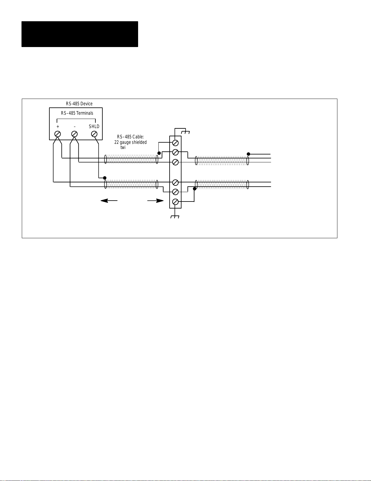
Appendix B
Communications Application Note
RS-485 Device
RS–485 T erminals
+ – SHLD
Figure B–3
RS–485 Intermediate Terminal Strip Connection
TERMINAL STRIP
RS–485 Cable:
22 gauge shielded
twisted pair
T o IBM PC or other
RS–485 devices
T o IBM PC or other
RS–485 devices
DISTANCE X
NOTE: When an intermediate terminal block is used to connect any device to the RS–485 bus, the length of the cable segments between the device and the terminal
block must be taken into account when calculating the overall length of cable (4,000 ft. max.). This length is equal to 2 times distance X in the diagram.
Calculating Overall Cable Length
When determining the overall length of an RS–485 communication straight
line or loop connection, it is important to account for all cable segments.
For example, when RS–485 connections to the device are made via an
intermediate terminal block, the lengths of cable between the device and the
terminal block must be added to the total cable distance (see Figure B–3).
Using Modems
If communications over a telephone network is used with modems, each
modem will require configuration.
DIP Switch Configuration
If the modems used are configured using hardware DIP switches or a similar
method, set the DIP switches to provide the functionality outlined in Chapter
3, Section 3.1.3.
Configuration Via
Communications – Standard
Modem Setup
B–6
For modems that are configured via their communications port, the
Powermonitor Software automatically executes a predefined procedure at the
time that the operator selects the MODEM (TOUCH TONE) or MODEM
(PULSE) option in the CONNECTION screen.
This procedure automatically transmits two sets of commands to the
modem(s) which will configure both a Hayes–compatible 2400 baud modem
and a Hayes–compatible 9600 baud modem.
Page 75

Appendix B
Communications Application Note
Configuration Via
Communications – Custom
Modem Setup
If the modem you are using requires a unique set of configuration
commands, a modem configuration file with the name MODEM.CFG must
be created and placed in the SP directory. This file may be created using any
ASCII text editor; however, a quick way to create the file is to use a simple
DOS line editor. This can be run by using the following DOS command:
TYPE CON MODEM.CFG <Enter>
The operator should then type in the sequence of modem commands
necessary to configure the device. The device must be configured to provide
the functionality outlined in Chapter 3, ‘‘Installation.” Refer to the manual
for the modem to determine the communications commands necessary to
perform the configuration.
ATTENTION: It is extremely important that information is
entered correctly into the MODEM.CFG file. Any errors may
!
incorrectly configure a modem, which may cause malfunctions
when running the Powermonitor Software.
When the complete string has been entered, press:
Ctrl + Z
to escape from the DOS line editor.
Save the MODEM.CFG file in the SP directory. When the Powermonitor
Software is run, and either of the MODEM options is selected in the
CONNECTION screen, the Powermonitor Software will use the data found
in the MODEM.CFG file to configure the connected modem(s).
B–7
Page 76

Appendix B
Communications Application Note
B–8
Page 77

Appendix
C
Setpoint Parameter Form
SETPOINT FUNCTION HIGHLIMIT TDOPERATE LOWLIMIT TDRELEASE RELAY/FUNCITON
1
2
3
4
5
10
11
12
13
14
15
6
7
8
9
16
17
C–1
Page 78

Appendix C
Setpoint Parameter Form
C–2
Page 79

Appendix
D
Keyboard Reference
Table 1.A
FUNCTION KEY(s) DESCRIPTION
Move Cursor
Available on most screens
Toggle or Modify Value
Help Line at bottom of
each screen indicates
which key functions avail-
able to modify selected
field.
Select or Display
Available on most
screens.
Exit Esc Returns to MAIN MENU.
Save & Exit
Available on Device Setup, Setpoint/Relay setup
and Label Setup screens.
Select Data Screen F1 to F6 Shortcut keys for selecting one of 6 possible remote device
Save to Disk File F7 Saves the present contents of the remote device
Arrows
Home
End
PgUp
PgDn
Plus <+>
Minus <–>
Digits
Text
Enter Selects the desired function or sub–menu.
Esc Sends Device Setup, Setpoint, or Label changes to remote
Moves cursor one field in direction of arrow.
Moves the cursor to the field at the top of the list.
Moves the cursor to the field at the bottom of the list.
Moves the cursor up the list by one page
Moves the cursor down the list by one page.
Toggles the field value to the next selection.
Toggles the field value to the previous selection.
Field can contain only a numerical value.
Field can contain any combination of letters & digits.
device then returns to MAIN MENU.
data screens.
Event, Min/Max or Snapshot Log to a disk file which may
be printed out later.
Update Unit Time F8 Sets internal clock of remote device to time read from
computer internal clock.
D–1
Page 80

Appendix D
Keyboard Reference
D–2
Page 81

Appendix
Appendix
E
Loading Event, MIN/MAX, or Snapshot
Log Files Into Lotus
Spreadsheet programs such as Lotus 123 can be used to analyze,
sort, perform calculations, and graph the data contained in the
snapshot, MIN/MAX, and event log files. To use the Snapshot
logs with Lotus 123, boot up Lotus, then import the
SNAPxxxx.log file using the following procedure:
1. Import the file by using the following Lotus command:
/file import text (filename = snapxxxx.log)
This will result in the snapshot file being loaded into the
spreadsheet as a text file. It now has to be converted into a
standard Lotus work sheet by using the “parse” command.
2. Put the cursor on cell A2; the first cell below the counter line
and perform the following commands:
a. Create a format line: /data parse format_line create
b. Edit the format line to define the first column as a date
column:
(/data parse format_line) edit and change the first
V>>> to D>>>.
c. Define the top left and bottom right corners of the data
which you wish to parse:
d. Define the output location where the parsed data will
be located (normally a column A cell a few lines below
the text data):
(/data parse) output–column
e. Do the parse: (/data parse) go
The original test format data should now be reproduced
in a WKS format just below the original data.
(/data parse) input–column
3. The text data should now be deleted:
/work sheet delete rows 1 to the beginning of the parsed data
4. The first two data and time columns need to be formatted to
display correctly. Format the entire first column to display
dates:
/range format date 5–short–intnl
5. Increase the width and change the format of the second
column to display the time:
/work sheet global column–width 10/range format date time
3–long intnl
6. Save the data as a standard Lotus file.
E–1
Page 82

Appendix E
Loading Logs into Lotus
AppendixAppendix
The snapshot log is now in a standard Lotus format. Standard
Lotus commands can now be used to sort, perform calculations,
and graph the data.
If you are going to be using this procedure frequently, a Lotus
Macro should be written to automate the process.
E–2
Page 83

Index
Installation and Operation Manual
Bulletin 1400 Powermonitor Software
C
catalog number explanation,
A–1
communications
RS–232C, 2–2
RS–485, 2–2
communications application
note, B–1
computer requirements, 2–1
I
installation, 3–1
communication hardware,
3–1
connection to a single
powermonitor via
RS–232C, 3–2
connection to multiple
powermonitors via
RS–485, 3–3
connection to multiple
powermonitors via
telephone net, 3–8
connection to remote sites
using other methods, 3–9
connection to single
powermonitor via
telephone net, 3–5
installing the software onto a
hard drive, 3–11
system software, 3–10
K
keyboard reference, D–1
L
P
Powermonitor data display and
configuration
clear functions, 5–17
configuring powermonitors,
displaying the setup or
setpoint parameters, 5–3
device setup, setup parameter
descriptions, 5–13, 5–15
displaying single device data
data display formats, 5–1
displaying additional data,
5–2
displaying device data, 5–1
to exit from any data
display screen, 5–3
event log, 5–7
main menu, 5–5
MIN/MAX log, 5–12
real time data, 5–6
setpoint/relay setup, 5–16
snapshot log, 5–8
status data
active alarms, 5–11
count, 5–11
date and time, 5–11
relay, 5–10
status input, 5–11
Powermonitor Display Module,
communication links, 1–2
Powermonitor internal relays,
6–1
Powermonitor Software, 1–1
backup copy, 3–10
installing the software onto a
hard drive, 3–11
operator support, 1–4
printer, 2–1
log disk files, 7–1
M
modem, 3–7
R
RS–232C communications,
2–2
RS–485 communications, 2–2
Index–1
Page 84

Index
Installation and Operation Manual
Bulletin 1400 Powermonitor Software
S
setpoint parameter form, C–1
software
connection screen, 4–3
main menu screen, 4–7
help/message line, 4–8
screen descriptions, 4–9
screens and functions, 4–8
shortcut keys, 4–9
on–line help, 4–11
startup, 4–1
update unit time, 4–11
system components, computer
station
modem connection, 1–1
remote connection, 1–1
system features
control, 1–3
data acquisition, 1–4
data display, 1–4
system requirements, 2–1
T
troubleshooting, 8–1
W
warranty, 9–1
firmware, 9–1
hardware, 9–1
software, 9–1
Index–2
Page 85

Page 86

With offices in major cities worldwide.
A subsidiary of Rockwell International, one of the world’s largest technology companies,
Allen-Bradley meets today’s automation challenges with over 85 years of practical plant floor
experience. 11,000 employees throughout the world design, manufacture and apply a wide
range of control and automation products and supporting services to help our customers
continuously improve quality, productivity and time to market. These products and services
not only control individual machines, but also integrate the manufacturing process while
providing access to vital plant floor data that can be used to support decision–making
throughout the enterprise.
WORLD HEADQUARTERS
Allen-Bradley
1201 South Second Street
Milwaukee, WI 53204 USA
Tel: (1) 414 382–2000
Telex: 43 11 016
FAX: (1) 414 382–4444
EUROPE/AFRICA
HEADQUARTERS
Allen–Bradley GmbH
European Commercial Headquarters
Robert–Bosch–Strasse 5
6072 Dreieich–Sprendlingen
Tel: (49) 6103–379733
FAX: (49) 6103–379731
Publication 1400–801 — April 1993
ASIA/PACIFIC HEADQUARTERS
Allen–Bradley
1201 South Second Street
Milwaukee, WI 53204 USA
Tel: (1) 414 382-3269
Telex: 43 11 016
FAX: (1) 414 382-4050
CANADA HEADQUARTERS
Allen–Bradley Canada Limited
135 Dundas Street
Cambridge, Ontario N1R 5X1
Canada
Tel: (1) 519 623–1810
FAX: (1) 519 623–8930
1993 Allen-Bradley Company Printed in USA
LATIN AMERICA
HEADQUARTERS
Allen-Bradley
1201 South Second Street
Milwaukee, WI 53204 USA
Tel: (1) 414 382–2000
Telex: 43 11 016
FAX: (1) 414 382–2400
40055–099–01(A)
 Loading...