

Page 1
ALLEN-BRADLEY
A–B
Bulletin 1400
Power Monitoring Products
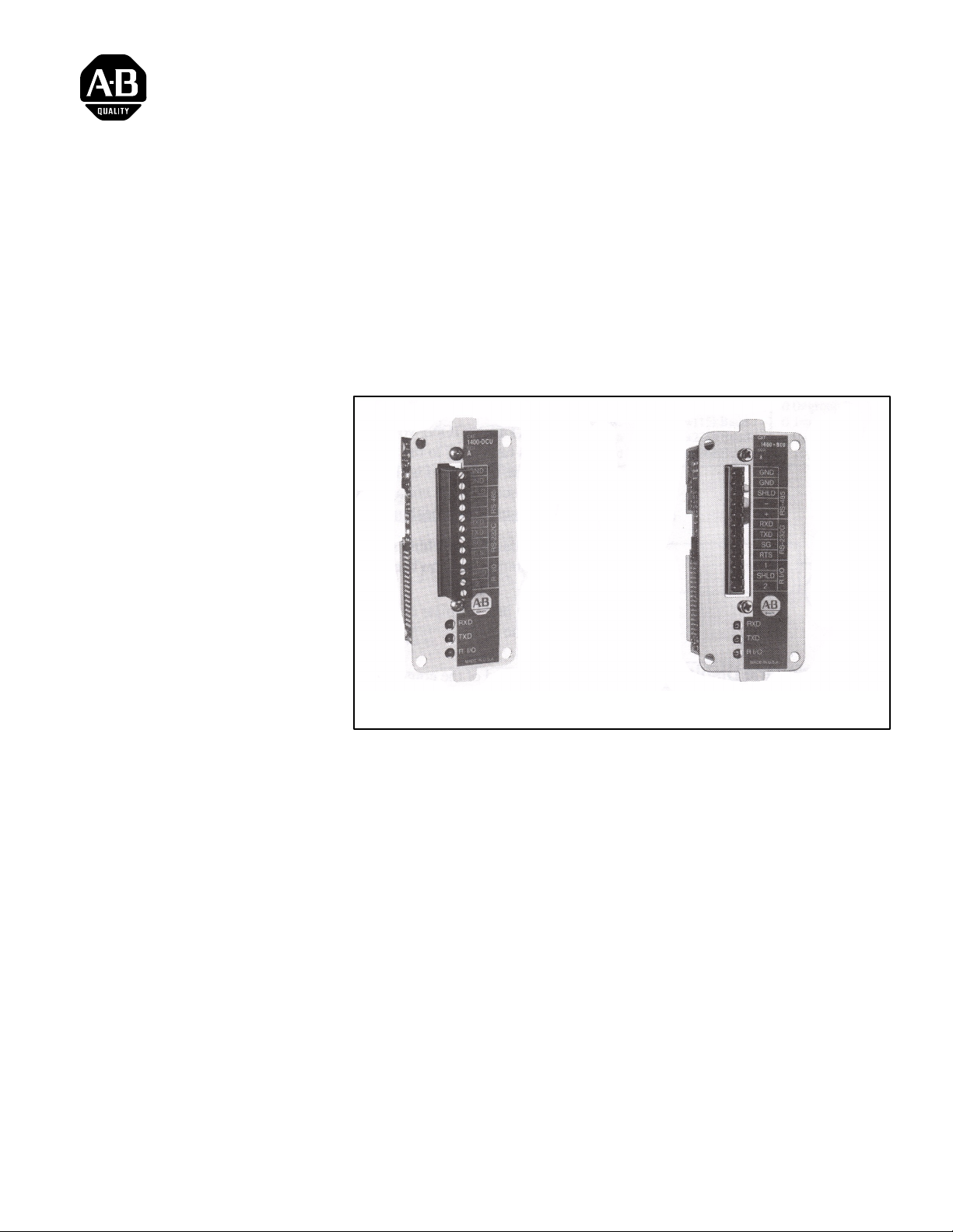
Bulletin 1400-DCU/BCU Communications Card
Instruction Sheet
Description
Field Retrofit and Configuration of the Communications Card
Bulletin 1400–DCU
The Bulletin 1400-DCU/BCU Communications Card supports Remote I/O
and can be optionally configured as either RS-485 or RS-232C. Remote I/O
and one of the two open architectures are active at all times. RS-232C or
RS-485 are selected by means of a jumper.
Note: Bulletin 1400–DCU is used with the Powermonitor Display Module
and Bulletin 1400–BCU is used with the Powermonitor Block Module.
This section explains the procedure for installing a universal communications
card or changing the communications mode.
The card has a jumper block to allow the user to select RS-232C or RS-485
mode. The card’s currently selected communications mode may be viewed
from the front panel of the Powermonitor Display Module, if the unit is
operating, (see Publication 1400-5.2, Chapter 3, “Field Programming”), or
by removing the card and examining the position of the jumper block.
Bulletin 1400–BCU
Page 2
Instruction Sheet
B
Bulletin 1400
Power Monitoring Products
Removing An Existing Card
ATTENTION: An anti–static wrist grounding strap must be
worn at all times while performing any reconfigurations or
!
modifications to the Powermonitor Display/Block Module.
Failing to do so may permanently damage the static–sensitive
components inside the Powermonitor Display/Block Module.
1. Turn off all power to the Powermonitor Display/Block Module.
ATTENTION: Voltages may still be present when supply power
is turned off to the unit. The unit will generally be powered by
!
one source and will be monitoring another source. Turn off or
disconnect all voltages applied to the unit. Failure to do so may
result in personal injury or death.
Configuring the Display Communications Card
Configuring the
lock
Communications Card
2. Remove the four machine screws holding the rectangular communications
card mounting plate on back of the Powermonitor Display/Block Module.
case.
3. Carefully pull the plate away from the main chassis using the pull tabs to
remove the card.
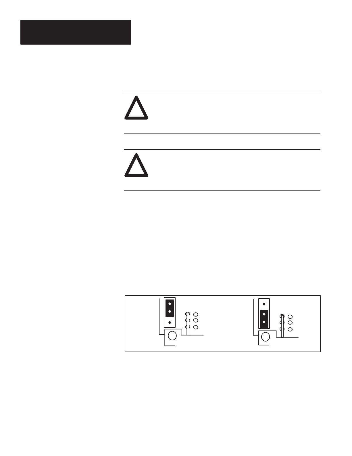
The circuit board of the communications card has a jumper labelled Jl. This
jumper has two positions, which determine the communications mode.
Figure 1 illustrates the jumper in the bottom position for RS-485 mode. If
the RS-232C mode is desired, move the jumper into the top position.
Figure 1
Communications Card Jumper Configuration
RS–232C Mode
(T op Position)
The Powermonitor Block Communications card has a jumper labelled J1.
This jumper has two positions, which determine the communications mode.
The jumper is configured for RS–485 mode from the factory. If RS–232C
mode is desired, move the jumper over the two pins closest to the LEDs.
RS–485 Mode
(Bottom Position)
Remote I/O Addressing
The Powermonitor Block Communications card uses two DIP switches to
configure the RIO address, starting quarter, data rate, and last rack. The DIP
2
switches are shown in the default factory configuration.
Page 3

Instruction Sheet
R
Bulletin 1400
Power Monitoring Products
Use the following table to change the default configuration.
8 7 6 5 4 3 2 1
SW1
(1 = On)
SW2
(1 = On)
Figure 2
Communications Card Jumper and Switch Locations
not used
set=1
8 7 6 5 4 3 2 1
not
used
set=1
last
rack
0=no
1=yes
last rack
6 5
0 0=hold
0 1=low
1 0=high
1 1=hold
RIO rack address 0–63 (00–77 octal)
data rate
4 3
0 0=57.6kBaud
0 1=115kBaud
1 0=230kBaud
1 1=230kBaud
group number
2 1
0 0=group 0
0 1=group 2
1 0=group 4
1 1=group 6
einstalling (or Field
Retrofitting) the
Communications Card
RS 232
RS 485
J1
SW2
12345678
ON
12345678
SW1
ON
1. Make sure that all power to the Powermonitor Display/Block Module
is off.
ATTENTION: Voltages may still be present when supply power
is turned off to the unit. The unit will generally be powered by
!
one source and monitoring another source. Turn off or
disconnect all voltages applied to the unit. Failure to do so may
result in personal injury or death.
2. If field retrofitting a Powermonitor Display/Block Module, first remove
the communications port cover plate on the rear cover of the
Powermonitor Display/Block Module.
3
Page 4

Instruction Sheet
Terminal Stri
R
p
Bulletin 1400
Power Monitoring Products
einstalling (or Field
Retrofitting) the
Communications Card
(continued)
3. Install the new card as follows:
a.. Insert the communications card into the communications port
insuring that the communications card is oriented such that it will
mate properly with the edge connector on the main board inside the
Powermonitor Display/Block case.
Important: The card is polarized to ensure installation in the correct
orientation.
b.. Align the holes in the mounting plate of the card with the mounting
holes in the Powermonitor Module rear cover while lowering the
card towards its seating. The installer will be able to feel when the
card has found the correct alignment with the edge connector.
c.. Once the board is resting in proper alignment on the edge
connector, carefully press down to plug the card into the edge
connector.
d.. Install the four mounting screws through the mounting plate to
secure the card in position.
e.. Make all necessary communications connections to the
communications card. Communications connection information
can be found in Chapter 2 of Publication 1400–5.2, “Bulletin 1400
Power Monitor Installation and Operation” manual.
f.. The card is now ready for use.
Publication 1400–5.0 – June 1995
Supersedes Publication 1400-5.0 – February 1994
ecifications
S
ALLEN-BRADLEY
A ROCKWELL INTERNATIONAL COMPANY
4
INPUT & OUTPUT RATINGS
p
Operating Temp.
Storage Temp.
Humidity 5 to 95 percent, non–condensing
Isolation 500 Volts RMS
RS-232/RS-485
Baud Rate
Remote I/O
Baud Rate
Energy Class Class 2 Energy Limited
Torque 5 lb-in (0.56 Nm) Torque
Maximum Wire
0° C to 50° C (32° F to 122° F) ambient air temperature range
–30°C to + 70°C (–22°F to 158°F)
300 to 19,200 Baud
57.6kBaud, 115kBaud, 230kBaud
14 AWG, 2.5 mm2, 75° C CU Wire Only
1995 Allen-Bradley Company, Inc.
40055–100–01(C)
PRINTED IN USA
 Loading...