

Page 1

Allen-Bradley
Bulletin 1203
Serial Communications
User
Module
(Series B)
RS232/422/483 (Using DF1 Protocol)
DH485
(Cat. No. 1203–GD2, –GK2, –GM2)
Manual
Page 2

Important User Information
Solid state equipment has operational characteristics differing from
those of electromechanical equipment. “Safety Guidelines for the
Application, Installation and Maintenance of Solid State Controls”
(Publication SGI-1.1) describes some important differences between
solid state equipment and hard–wired electromechanical devices.
Because of this difference, and also because of the wide variety of
uses for solid state equipment, all persons responsible for applying
this equipment must satisfy themselves that each intended
application of this equipment is acceptable.
In no event will the Allen-Bradley Company be responsible or liable
for indirect or consequential damages resulting from the use or
application of this equipment.
The examples and diagrams in this manual are included solely for
illustrative purposes. Because of the many variables and
requirements associated with any particular installation, the
Allen-Bradley Company cannot assume responsibility or liability for
actual use based on the examples and diagrams.
No patent liability is assumed by Allen-Bradley Company with
respect to use of information, circuits, equipment, or software
described in this manual.
Reproduction of the contents of this manual, in whole or in part,
without written permission of the Allen-Bradley Company is
prohibited.
Throughout this manual we use notes to make you aware of safety
considerations.
ATTENTION: Identifies information about practices
or circumstances that can lead to personal injury or
!
Attentions help you:
death, property damage, or economic loss.
• identify a hazard
• avoid the hazard
• recognize the consequences
Important: Identifies information that is especially important for
successful application and understanding of the product.
PLC, PLC–2, PLC–3, PLC–5, SLC, SLC 500, PanelView, RediPANEL, Data Highway Plus, and Dataliner are trademarks of
Allen-Bradley Company, Inc.
IBM is a registered trademark of International Business Machines, Incorporated.
Page 3

Preface
Table of Contents
Who Should Use this Manual P–1. . . . . . . . . . . . . . . . . . . . . . . . . . . .
Purpose of this Manual P–1. . . . . . . . . . . . . . . . . . . . . . . . . . . . . . . . .
Contents of this Manual P–2. . . . . . . . . . . . . . . . . . . . . . . . . . . .
Related Documentation P–2. . . . . . . . . . . . . . . . . . . . . . . . . . . .
Terms and Abbreviations P–3. . . . . . . . . . . . . . . . . . . . . . . . . . . . . . .
Conventions P–3. . . . . . . . . . . . . . . . . . . . . . . . . . . . . . . . . . . . . . . .
Firmware Support P–3. . . . . . . . . . . . . . . . . . . . . . . . . . . . . . . . . . . .
Safety Precautions P–3. . . . . . . . . . . . . . . . . . . . . . . . . . . . . . . . . . . .
Serial Device Compatibility P–4. . . . . . . . . . . . . . . . . . . . . . . . . . . . . .
Allen–Bradley Support P–4. . . . . . . . . . . . . . . . . . . . . . . . . . . . . . . . .
Local Product Support P–4. . . . . . . . . . . . . . . . . . . . . . . . . . . . .
Technical Product Assistance P–4. . . . . . . . . . . . . . . . . . . . . . . .
Product Description
Installation
Chapter 1
Chapter Objectives 1–1. . . . . . . . . . . . . . . . . . . . . . . . . . . . . . . . . . .
Module Description 1–1. . . . . . . . . . . . . . . . . . . . . . . . . . . . . . . . . . .
SCANport Device Compatibility 1–2. . . . . . . . . . . . . . . . . . . . . . . . . . .
Configuration Switches 1–6. . . . . . . . . . . . . . . . . . . . . . . . . . . . . . . . .
Chapter 2
Chapter Objectives 2–1. . . . . . . . . . . . . . . . . . . . . . . . . . . . . . . . . . .
Setting Module Configuration Switches 2–1. . . . . . . . . . . . . . . . . . . . .
Switch SW1 2–3. . . . . . . . . . . . . . . . . . . . . . . . . . . . . . . . . . . .
DF1/DH–485 Address Selection 2–4. . . . . . . . . . . . . . . . . . . . . .
DF1 Address Selection 2–5. . . . . . . . . . . . . . . . . . . . . . . . . . . . .
Switch SW2 2–6. . . . . . . . . . . . . . . . . . . . . . . . . . . . . . . . . . . .
Switch SW3 2–8. . . . . . . . . . . . . . . . . . . . . . . . . . . . . . . . . . . .
Mounting the Serial Communications Module 2–10. . . . . . . . . . . . . . . . .
Enclosed Style Serial Communications Module Dimensions 2–12. . . . . .
Connecting Cables 2–13. . . . . . . . . . . . . . . . . . . . . . . . . . . . . . . . . . .
1746-BAS Module Serial Connections 2–13. . . . . . . . . . . . . . . . . .
IBM PC Compatible Serial Connections 2–14. . . . . . . . . . . . . . . . .
1747–AIC Link Coupler Serial Connections 2–14. . . . . . . . . . . . . .
PLC5 Channel 0 Serial Connections 2–15. . . . . . . . . . . . . . . . . . .
SCANport Link Connection 2–16. . . . . . . . . . . . . . . . . . . . . . . . . . . . . .
1305 Drive 2–16. . . . . . . . . . . . . . . . . . . . . . . . . . . . . . . . . . . . .
1336 PLUS and 1336 FORCE 2–17. . . . . . . . . . . . . . . . . . . . . .
1394 2–17. . . . . . . . . . . . . . . . . . . . . . . . . . . . . . . . . . . . . . . . . .
SMP 3 2–17. . . . . . . . . . . . . . . . . . . . . . . . . . . . . . . . . . . . . . . .
Power Supply Connections 2–18. . . . . . . . . . . . . . . . . . . . . . . . . . . . . .
Page 4

Table of Contentsii
SCANport Datalink
Operation
Configuring and Interfacing
Block Transfer Emulation
Instructions
Chapter 3
Chapter Objectives 3–1. . . . . . . . . . . . . . . . . . . . . . . . . . . . . . . . . . .
SCANport Datalinks 3–1. . . . . . . . . . . . . . . . . . . . . . . . . . . . . . . . . . .
Chapter 4
Chapter Objectives 4–1. . . . . . . . . . . . . . . . . . . . . . . . . . . . . . . . . . .
Serial Communications Module Data Table Structure 4–1. . . . . . . . . . .
Supported PCCC Command List 4–2. . . . . . . . . . . . . . . . . . . . . .
Data Table Structure 4–3. . . . . . . . . . . . . . . . . . . . . . . . . . . . . .
Configuration Examples 4–9. . . . . . . . . . . . . . . . . . . . . . . . . . . . . . . .
DF1 Messaging with a PLC–5/80 Example 4–9. . . . . . . . . . . . . . .
DF1 Messaging with a 1746–BAS Module Example 4–1 1. . . . . . . .
DH–485 Messaging with a SLC5/03 Interface 4–13. . . . . . . . . . . . .
Chapter 5
Chapter Objectives 5–1. . . . . . . . . . . . . . . . . . . . . . . . . . . . . . . . . . .
Block Transfer Status Word 5–1. . . . . . . . . . . . . . . . . . . . . . . . . . . . .
Scattered Parameter Value Read 5–2. . . . . . . . . . . . . . . . . . . . . . . . .
Scattered Parameter Value Write 5–4. . . . . . . . . . . . . . . . . . . . . . . . .
Product ID Number Read 5–6. . . . . . . . . . . . . . . . . . . . . . . . . . . . . . .
Parameter Read Full 5–8. . . . . . . . . . . . . . . . . . . . . . . . . . . . . . . . . .
Parameter Value Read 5–11. . . . . . . . . . . . . . . . . . . . . . . . . . . . . . . . .
Parameter V alue W rite 5–12. . . . . . . . . . . . . . . . . . . . . . . . . . . . . . . . .
EE Memory Functions 5–13. . . . . . . . . . . . . . . . . . . . . . . . . . . . . . . . .
Fault Clear/Reset 5–15. . . . . . . . . . . . . . . . . . . . . . . . . . . . . . . . . . . . .
Fault Queue Entry Read Full 5–16. . . . . . . . . . . . . . . . . . . . . . . . . . . . .
Fault Queue Size 5–18. . . . . . . . . . . . . . . . . . . . . . . . . . . . . . . . . . . . .
Trip Fault Queue Number 5–19. . . . . . . . . . . . . . . . . . . . . . . . . . . . . . .
Troubleshooting
Specifications
Chapter 6
Chapter Objectives 6–1. . . . . . . . . . . . . . . . . . . . . . . . . . . . . . . . . . .
LED Locations 6–1. . . . . . . . . . . . . . . . . . . . . . . . . . . . . . . . . . .
LED Troubleshooting Table 6–2. . . . . . . . . . . . . . . . . . . . . . . . . .
Chapter 7
Chapter Objectives 7–1. . . . . . . . . . . . . . . . . . . . . . . . . . . . . . . . . . .
Product Specifications 7–1. . . . . . . . . . . . . . . . . . . . . . . . . . . . .
Module Compatibility 7–1. . . . . . . . . . . . . . . . . . . . . . . . . . . . . . . . . .
Page 5

Preface
Preface
Read this preface to familiarize yourself with the rest of the manual.
This preface covers the following topics:
• who should use this manual
• the purpose of this manual
• terms and abbreviations
• conventions used in this manual
• safety precautions
• Allen–Bradley support
Who Should Use this Manual
Purpose of this Manual
Use this manual if you are responsible for setting up and servicing
the Serial Communications Module. You must have previous
experience with and a basic understanding of communications
terminology, configuration procedures, required equipment, and
safety precautions.
To use this Serial Communications Module efficiently, you must be
able to program and operate serial communications devices, as well
as have a basic understanding of the parameter settings and functions
of the device to which you are communicating.
This manual is an installation and user guide for the Serial
Communications Module. The Serial Communications Module is
available for products that include the SCANport communications
port.
This manual provides you with the following:
• an overview of the Serial Communications Module
• the procedures you need to install, configure, and troubleshoot the
Serial Communications Module
For information on specific features of Allen–Bradley products
mentioned within this manual, refer to the user manual for that
product.
Important:You should read this manual in its entirety before
installing, operating, servicing, or initializing the Serial
Communications Module.
1203–5. 5 September 1995
Page 6

P–2
Contents of this Manual
Chapter Title Contents
Describes the purpose, background, and scope of
Preface
this manual. Also specifies the audience for whom
this manual is intended.
1 Product Description
2 Installation
3
4
5
6 Troubleshooting
7 Specifications
SCANport Datalink
Operation
Configuring and
Interfacing
Block Transfer Emulation
Instructions
Explains the Serial Communications Module’s
features, configuration, and diagnostics.
Provides procedures for mounting, connecting
power, configuring switches, cabling, and
connecting hardware.
Provides information for configuring SCANport
device datalinks and datalink operation.
Provides information about addressing, information
transfer, and sample programs.
Provides information for using the block transfer
emulation instructions.
Explains how to interpret and correct problems with
your Serial Communications Module.
Provides environmental, electrical, and
communications specifications.
Related Documentation
The following documents contain additional information concerning
Allen–Bradley SLCt and PLC products. To obtain a copy, contact
your local Allen–Bradley office or distributor.
For Read This Document
Information about the DH–485 network
Additional information about setting up the DH–485 network on
your SLC 500
A complete listing of current Allen–Bradley documentation,
including ordering instructions. Also indicates whether the
documents are available on CD–ROM or in multi–languages.
A glossary of industrial automation terms and abbreviations Allen–Bradley Industrial Automation Glossary AG–7.1
Information about the MSG block Instruction Set Reference 6200–6.4.11
Information about configuring the PLC–5 channel 0 hardware Hardware Installation Manual 1785–6.6.1
Information about configuring the PLC–5 channel 0 driver Software Configuration and Maintenance 6200–6.4.6
1203–5.5 September 1995
Data Highway/Data Highway Plus/DH–485
Communication Protocol and Command Set
SLC 500 Modular Hardware Style
Allen–Bradley Publication Index SD499
Document
Number
1770–6.5.16
1747–NI002,
Series A
Page 7

Preface P–3
Terms and Abbreviations
Conventions
The following terms and abbreviations are specific to this product.
For a complete listing of Allen–Bradley terminology, refer to the
Allen–Bradley Industrial Automation Glossary, Publication Number
ICCG–7.1. In this manual, we refer to the:
• Variable Frequency AC Drive (Bulletin 1305, 1336 FORCE,
1336 PLUS, 1395, 1557, SMC, SMC Plus, or SMC dialog) as
the drive or SCANport device.
• Programmable Logic Controller as the Programmable Controller
or PLC.
• Earth Ground as GND.
The following conventions are used throughout this manual:
• Bulleted lists such as this one provide information, not procedural
steps.
• Numbered lists provide sequential steps or hierarchical
information.
• Italic type is used for emphasis.
• Text in this font indicates words or phrases you should type.
Firmware Support
Safety Precautions
This manual supports communications module firmware versions
2.xx (the “xx” designator may vary). Features that work with
specific firmware versions will be denoted as such.
ATTENTION: Only personnel familiar with
SCANport devices and associated machinery should
!
!
plan or implement the installation, start–up,
configuration, and subsequent maintenance of the serial
communications module. Failure to comply may result
in personal injury and/or equipment damage.
ATTENTION: This module contains Electrostatic
Discharge (ESD) sensitive parts and assemblies. Static
control precautions are required when installing,
testing, servicing, or repairing this assembly.
Component damage may result if ESD control
procedures are not followed. If you are not familiar
with static control procedures, refer to Allen–Bradley
Publication 8000–4.5.2, Guarding Against Electrostatic
Damage or any other applicable ESD protection
handbook.
1203–5.5 September 1995
Page 8

P–4
Serial Device Compatibility
Allen–Bradley Support
This Serial Communications Module is intended for use with devices
that communicate via the following protocols:
Hardware Standard Communications Protocol
RS–232 DF1
RS–422 DF1
RS–485 DF1
DH–485 DH–485
Allen–Bradley offers support services worldwide, with over 75
Sales/Support Offices, 512 authorized Distributors, and 260
authorized Systems Integrators located throughout the United States
alone, plus Allen–Bradley representatives in every major country in
the world.
Local Product Support
Contact your local Allen–Bradley representative for:
• sales and order support
• product technical training
• warranty support
• support service agreements
Technical Product Assistance
If you need to contact Allen–Bradley for technical assistance, please
review the information in the Troubleshooting chapter first. Then
call your local Allen–Bradley representative.
1203–5.5 September 1995
Page 9

Product Description
Chapter
1
Chapter Objectives
Module Description
In this chapter, you will read about:
• Serial Communications Module features
• the location of configuration switches
The Serial Communications Module is an optional interface device
designed to provide a direct digital link between serial
communications devices and any device that uses SCANport. The
current list of products that use SCANport includes: 1305, 1336
PLUS, 1336 FORCE, 1394, SMP3 controllers, and 1557 medium
voltage drives. The module connects to these products via
SCANport.
The Serial Communications Module is available in both Open style
(Figure 1.1) and Enclosed (Figure 1.2) type configurations. The
Open style module mounts inside certain drives, depending on drive
size. The Enclosed module mounts independently and can be used
with any SCANport device. The following table provides more
information about the Open and Enclosed styles.
Designation Enclosure Power Supply Source Used With
Open Style Open PC Board Supplied by the drive 1336 PLUS*
Enclosed IP30 24V DC separately supplied or
120/240V AC separately supplied
* 7.5HP and higher sizes only, excluding the AQF and BRF catalog number drives
** 7.5HP and higher sizes with Standard Adapter board only
*** analog 1394 only
1336 FORCE**
1394***
1336 PLUS
1336 FORCE
Other SCANport products
1305
1394
SMP3
1203–5.5 September 1995
Page 10

1–2 Product Description
SCANport Device Compatibility
The SCANport Serial Communications Module is compatible with
the following Allen–Bradley devices:
Device Firmware Revision
1336 PLUS All
1336 FORCE All
1305 Micro Drive 2.0 or newer
SMC
SMP
1394
1557
1203–5.5 September 1995
Page 11
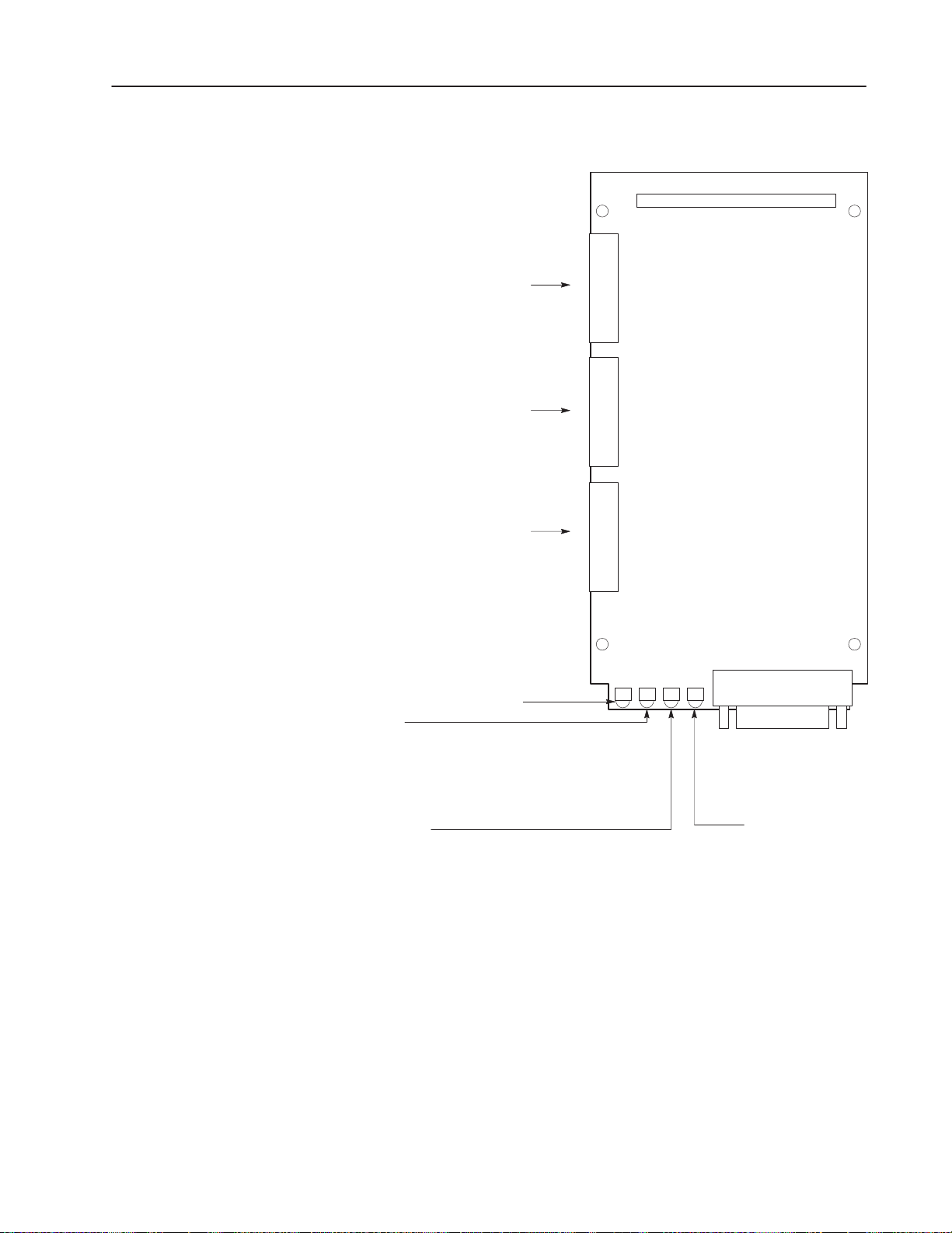
Figure 1.1
Open Style Communications Module
SW1.1 – SW1.2 = Protocol select
SW1.3 – SW1.8 = Adapter address
1–3Product Description
J4
1
2
3
SW1
4
5
6
7
8
SW2.1 – SW2.3 = Baud rate selection
SW2.4 = Parity enable
SW2.5 = Parity sense (even/odd)
SW2.6 = Stop bits
SW2.7 = Point-to-point/multi-drop
SW2.8 = CRC/BCC check
SW3.1 = Logic command/status and
reference/feedback
SW3.2 = Datalink A settings
SW3.3 = Datalink B settings
SW3.4 = Datalink C settings
SW3.5 = Datalink D settings
SW3.6 = Duplicate message detection
SW3.7, SW3.8 = Application timeout
default value
TX (Adapter transmit) when flashing
Serial Status
1. LED off: adapter power removed
2. LED flashing green: link OK, off–line
3. LED solid green: link OK, on–line
4. LED flashing red: was on–line, now off–line
5. LED solid red: fault
1
2
3
4
5
6
7
8
1
2
3
4
5
6
7
8
SW2
SW3
LED Indicators
Serial
Communications
Module
J2
9-Pin D-shell
SCANport Status
1. LED off: adapter power removed
2. LED flashing green: link OK, not connected
3. LED solid green: link OK, connected
4. LED flashing red: was connected, now not connected
5. LED solid red: fault
RX (Adapter receive)
when flashing
AB0394C
1203–5.5 September 1995
Page 12
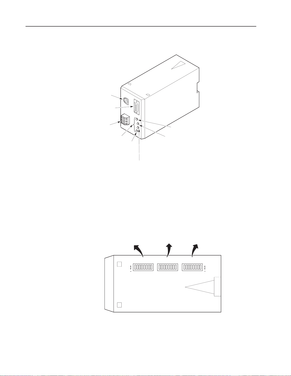
1–4 Product Description
Serial channel
D-shell connector
Figure 1.2
Enclosed Style Serial-to-SCANport Communications Module
SCANport
connector
Power
connection
Diagnostic
LEDs
TX
Serial Status
Switch SW3
– Logic command/status and
reference/feedback
– Datalink A, B, C, D settings
– Application timeout
Default value
– Duplicate message detection
O
RX
SCANport Status
1. LED off: adapter power removed
2. LED flashing green: link OK, not connected
3. LED solid green: link OK, connected
4. LED flashing red: was connected, now not connected
5. LED solid red: fault
1. LED off: adapter power removed
2. LED flashing green: link OK, off–line
3. LED solid green: link OK, on–line
4. LED flashing red: was on–line, now off–line
5. LED solid red: fault
Switch SW2
– Baud rate selection
– Parity enable
– Parity sense (even/odd)
– Stop bits
– Point-to-point/multi-drop
– CRC/BCC check
Switch SW1
– Protocol select
– Adapter address
SW1SW2SW3818181
O
1203–5.5 September 1995
Bottom View
AB0415B
Page 13
Open Style
Comm
Module
1336
1305
Micro
Drive
PLUS
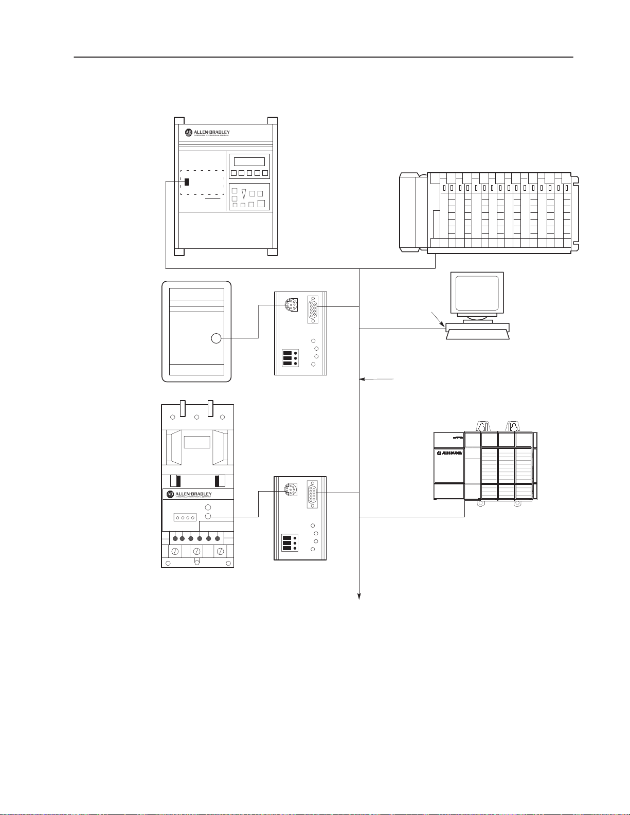
Figure 1.3
Typical Serial Communications/SCANport Device Interconnect
.
.
.
Serial port
SCANport
1–5Product Description
PLC
PC
SMP 3
SCANport
Serial
Communications
Module
Serial
Communications
Module
Other serial
devices
Serial communications link
SLC 5/03
SLC 5/03 CPU
AB0396C
1203–5.5 September 1995
Page 14
1–6 Product Description
Configuration Switches
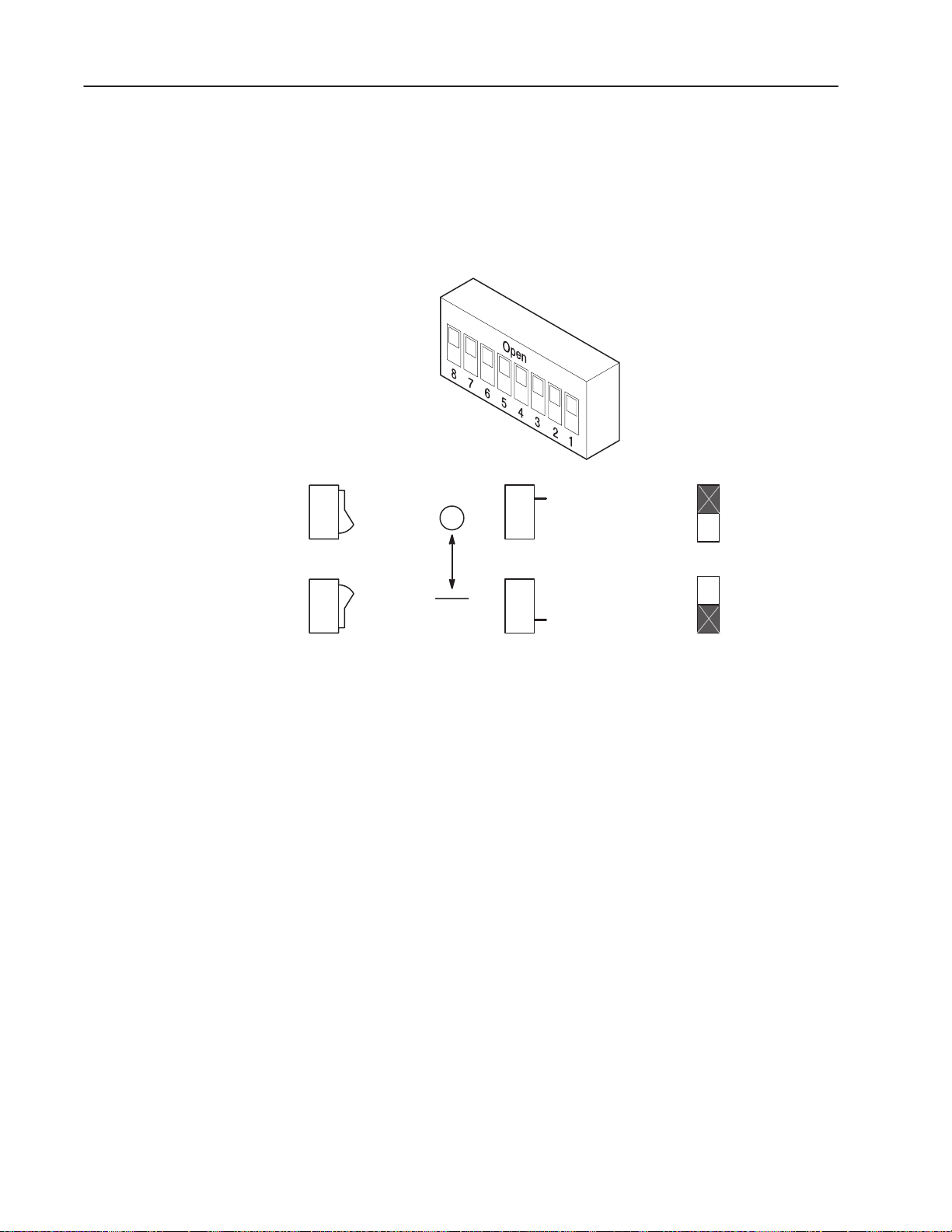
Figure 1.4
Configuration Switches
Rocker switch
Open
The Serial Communications Module contains three DIP Switches:
SW1, SW2, and SW3 (Figure 1.1 and Figure 1.2). Switches are set
ON or OFF as shown in Figure 1.4. For a detailed explanation of
switch configuration, refer to Chapter 2.
Side view of typical
switches
Side switch
Open
Open (Off)
Switch designation as
shown in this manual
Off
Open
Close (On)
Open
On
AB0397A
1203–5.5 September 1995
Page 15

Installation
Chapter
2
Chapter Objectives
Setting Module Configuration Switches
In this chapter, you will learn how to:
• set the module configuration switches
• mount the Serial Communications Module
• connect the cables
• connect the SCANport link
• connect the power supply
Read this chapter completely before you attempt to install or
configure your Serial Communications Module. Double check all
connections and option selections before you apply power.
Important: Switch selections take effect only on power–up. If you
change selections after power is applied, cycle the
power to use the new settings.
When making configuration changes to the Serial Communications
Module, use the addressing conventions of the PLC/SLC processor
or serial device through which you are communicating. In all cases,
each serial device must have a unique address that the target
processor can recognize.
"
ATTENTION: When changing the switch settings,
use a blunt, pointed instrument such as a ball point pen.
!
!
!
This publication describes switches as being either on or off. If the
switch assembly has the word OPEN printed on it, the word OPEN
corresponds to OFF (0).
If a switch is shown as gray, then that switch does not affect the
function being covered.
Do not use a pencil because the lead (graphite) of the
pencil may damage the switch assembly.
ATTENTION: Failure to check connections and
switch settings for compatibility with your application
when configuring the communications module could
result in personal injury and/or equipment damage due
to unintended or undesirable operation.
ATTENTION: It is recommended that when a system
is configured for the first time, you should disconnect
the motor from the machine or process during the
initial testing.
1203–5.5 September 1995
Page 16
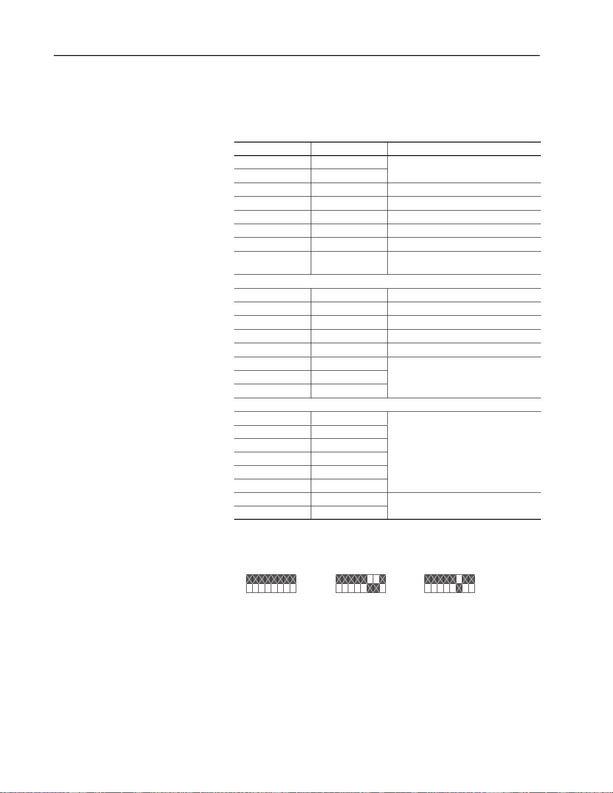
2–2 Installation
Factory Switch Settings
The following table shows the switch settings that are set at the
factory:
Switch Setting Communication Mode
SW3–8 Off Default application timeout disabled
SW3–7 Off
SW3–6 Off Duplicate message detection disabled
SW3–5 Off Datalink D disabled
SW3–4 Off Datalink C disabled
SW3–3 Off Datalink B disabled
SW3–2 Off Datalink A disabled
SW3–1 Off
SW2–8 Off BCC checksum
SW2–7 Off Point–to–point
SW2–6 Off 1 stop bit
SW2–5 Off Even parity (if enabled)
SW2–4 Off Parity disabled
SW2–3 On 9600 baud
SW2–2 On
SW2–1 Off
Logic command/status and
reference/feedback disabled
SW1–8 Off Module address = 1
SW1–7 Off
SW1–6 Off
SW1–5 Off
SW1–4 Off
SW1–3 On
SW1–2 Off RS–232 (DF1 protocol)
SW1–1 Off
These switches can be visually represented as follows:
SW3
O
–
87 654321
SW2
O
–
876543 21
SW1
O
–
87 654321
1203–5.5 September 1995
Page 17
2–3Installation
Switch SW1
Switch SW1 is used to select:
• serial communications mode (RS–232/RS–422/RS–485/DH–485)
• Serial Communications Module address
SW1
O
F
F
O
N
87 65 43 21
Communications
Module Address
Protocol
Selection
AB0398B
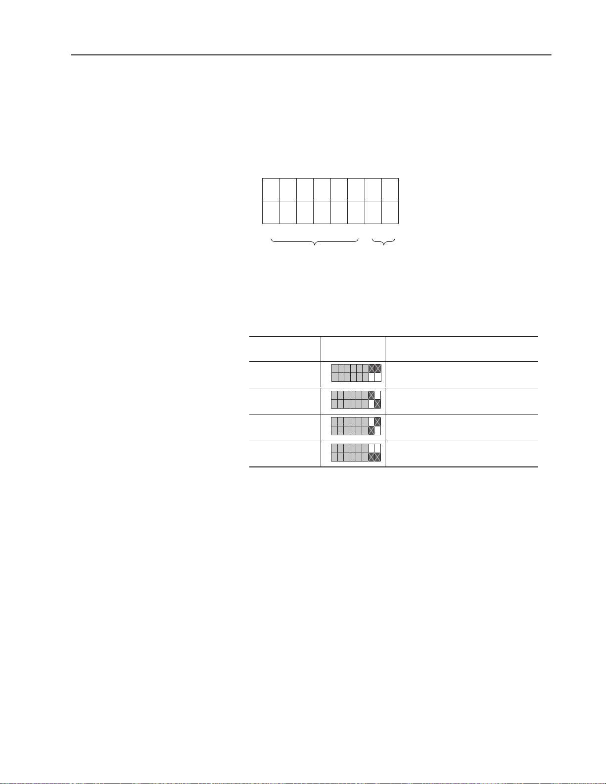
Use SW1–1 and SW1–2 to select the communications protocol you
are using:
Switch Value
(Decimal)
0
1
2
3
SW1 Protocol
O
–
87 654321
O
–
87 654321
O
–
87 654321
O
–
87 654321
RS–232 (DF1 protocol)
RS–422 (DF1 protocol)
RS–485 (DF1 protocol)
DH–485
1203–5.5 September 1995
Page 18
2–4 Installation
ÁÁÁÁ
Á
Á
Á
Á
Á
Á
Á
Á
Á
Á
Á
Á
Á
Á
Á
Á
Á
Á
Á
Á
Á
Á
Á
Á
Á
Á
Á
Á
Á
Á
Á
Á
Á
Á
Á
Á
Á
Á
Á
Á
Á
Á
Á
Á
Á
Á
Á
Á
Á
Á
Á
Á
Á
Á
Á
Á
Á
Á
Á
Á
Á
Á
Á
Á
Á
Á
Á
Á
Á
Á
Á
Á
Á
Á
Á
Á
Á
Á
Á
Á
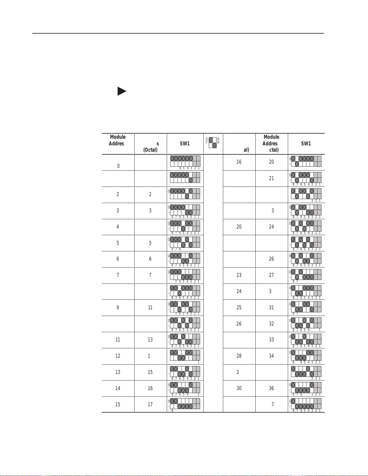
Use SW1–3, SW1–4, SW1–5, SW1–6, SW1–7, and SW1–8 to set
your address for the Serial Communications Module. The following
table provides the switch settings for selecting the serial device
addressing.
"
Module
Address
ÁÁ
(Decimal)
ÁÁ
0
1
ÁÁ
2
ÁÁ
3
4
ÁÁ
5
ÁÁ
6
ÁÁ
7
8
ÁÁ
9
ÁÁ
10
ÁÁ
11
12
ÁÁ
13
ÁÁ
14
ÁÁ
15
Note: If you are using the DH–485 communications mode, the
highest serial device address you can select is 31 (decimal).
DF1/DH–485 Address Selection
Module
Address
ÁÁÁ
(Octal)
0
ÁÁÁ
1
ÁÁÁ
2
ÁÁÁ
3
4
ÁÁÁ
5
ÁÁÁ
6
ÁÁÁ
7
10
ÁÁÁ
11
ÁÁÁ
12
ÁÁÁ
13
14
ÁÁÁ
15
ÁÁÁ
16
ÁÁÁ
17
SW1
ÁÁÁ
O
–
ÁÁÁ
87 654321
O
–
ÁÁÁ
876543 21
O
–
876543 21
O
ÁÁÁ
–
876543 21
O
–
ÁÁÁ
876543 21
O
–
ÁÁÁ
876543 21
O
–
876543 21
O
ÁÁÁ
–
876543 21
O
–
ÁÁÁ
876543 21
O
–
ÁÁÁ
876543 21
O
–
876543 21
O
ÁÁÁ
–
876543 21
O
–
ÁÁÁ
876543 21
O
–
ÁÁÁ
876543 21
O
–
876543 21
O
ÁÁÁ
–
876543 21
O
F
F
Á
ÁÁÁÁ
ÁÁÁÁ
ÁÁÁÁ
ÁÁÁÁ
ÁÁÁÁ
ÁÁÁÁ
ÁÁÁÁ
ÁÁÁÁ
ÁÁÁÁ
ÁÁÁÁ
ÁÁÁÁ
ÁÁÁÁ
O
N
Module
Address
ÁÁ
(Decimal)
16
17
18
19
20
21
22
23
24
25
26
27
28
29
30
31
Module
Address
ÁÁÁ
(Octal)
20
ÁÁÁ
21
ÁÁÁ
22
ÁÁÁ
23
24
ÁÁÁ
25
ÁÁÁ
26
ÁÁÁ
27
30
ÁÁÁ
31
ÁÁÁ
32
ÁÁÁ
33
34
ÁÁÁ
35
ÁÁÁ
36
ÁÁÁ
37
ÁÁÁ
O
–
ÁÁÁ
876543 21
O
–
ÁÁÁ
876543 21
O
–
876543 21
O
ÁÁÁ
–
876543 21
O
–
ÁÁÁ
876543 21
O
–
ÁÁÁ
876543 21
O
–
876543 21
O
ÁÁÁ
–
876543 21
O
–
ÁÁÁ
876543 21
O
–
ÁÁÁ
876543 21
O
–
876543 21
O
ÁÁÁ
–
876543 21
O
–
ÁÁÁ
876543 21
O
–
ÁÁÁ
876543 21
O
–
876543 21
O
ÁÁÁ
–
876543 21
SW1
1203–5.5 September 1995
Page 19
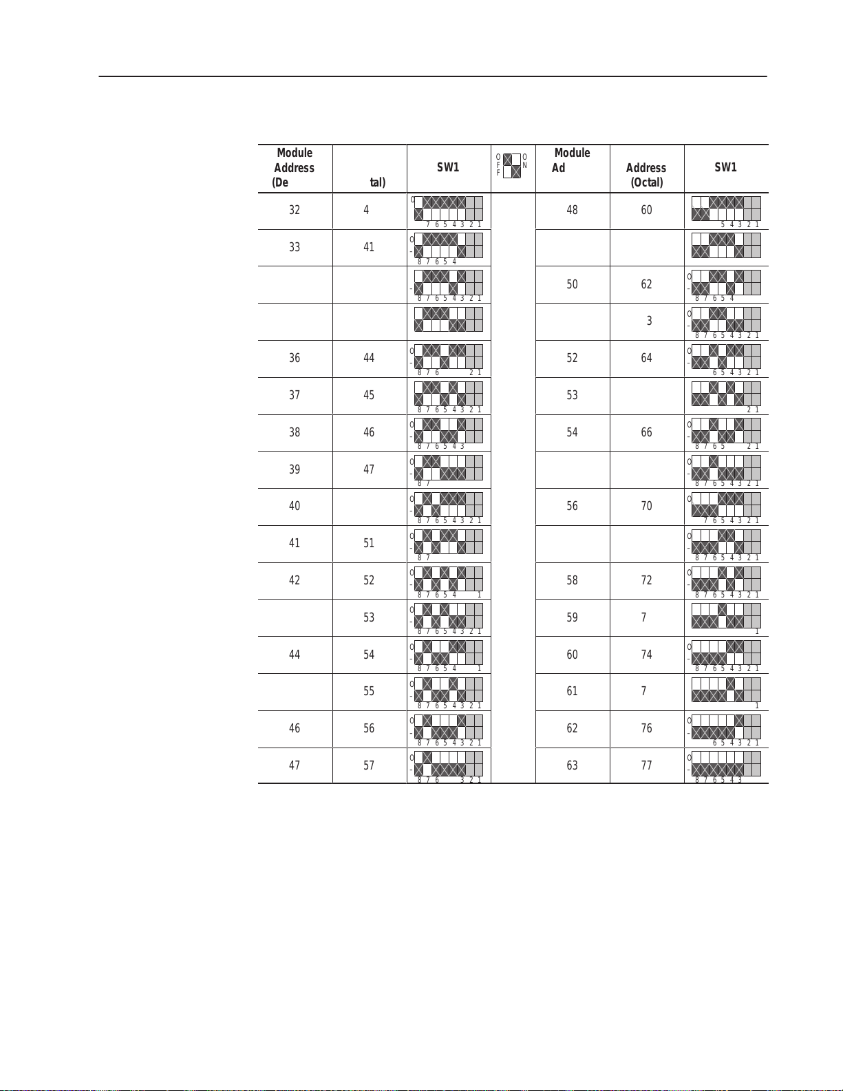
DF1 Address Selection
Á
Á
Á
Á
Á
Á
Á
Á
Á
Á
Á
Á
Á
Á
Á
Á
Á
Á
Á
Á
Á
Á
Á
Á
Á
Á
Á
Á
Á
Á
Á
Á
Á
Á
Á
Á
Á
Á
Á
Á
Á
Á
Á
Á
Á
Á
Á
Á
Á
Á
Á
Á
Á
Á
Á
Á
Á
Á
Á
Á
Á
Á
Á
Á
Á
Á
Á
Á
Á
Á
Á
Á
Á
Á
Á
Á
Á
Á
Á
Á
Á
Á
Á
Á
Á
Á
2–5Installation
Module
ÁÁ
Address
(Decimal)
ÁÁ
32
33
ÁÁ
34
ÁÁ
35
ÁÁ
36
37
ÁÁ
38
ÁÁ
39
ÁÁ
40
41
ÁÁ
42
ÁÁ
43
ÁÁ
44
45
ÁÁ
46
ÁÁ
47
ÁÁ
Module
ÁÁÁ
Address
(Octal)
ÁÁÁ
40
41
ÁÁÁ
42
ÁÁÁ
43
ÁÁÁ
44
45
ÁÁÁ
46
ÁÁÁ
47
ÁÁÁ
50
51
ÁÁÁ
52
ÁÁÁ
53
ÁÁÁ
54
55
ÁÁÁ
56
ÁÁÁ
57
ÁÁÁ
ÁÁÁ
SW1
ÁÁÁ
O
–
876543 21
O
ÁÁÁ
–
876543 21
O
–
ÁÁÁ
876543 21
O
–
876543 21
ÁÁÁ
O
–
876543 21
O
ÁÁÁ
–
876543 21
O
–
ÁÁÁ
876543 21
O
–
ÁÁÁ
876543 21
O
–
876543 21
O
ÁÁÁ
–
876543 21
O
–
ÁÁÁ
876543 21
O
–
ÁÁÁ
876543 21
O
–
876543 21
O
ÁÁÁ
–
876543 21
O
–
ÁÁÁ
876543 21
O
–
ÁÁÁ
876543 21
Á
F
Á
ÁÁÁÁ
ÁÁÁÁ
ÁÁÁÁ
ÁÁÁÁ
ÁÁÁÁ
ÁÁÁÁ
ÁÁÁÁ
ÁÁÁÁ
ÁÁÁÁ
ÁÁÁÁ
ÁÁÁÁ
ÁÁÁÁ
ÁÁ
Address
(Decimal)
ÁÁ
Module
O
O
N
F
48
49
50
51
52
53
54
55
56
57
58
59
60
61
62
63
Module
ÁÁÁ
Address
(Octal)
ÁÁÁ
60
61
ÁÁÁ
62
ÁÁÁ
63
ÁÁÁ
64
65
ÁÁÁ
66
ÁÁÁ
67
ÁÁÁ
70
71
ÁÁÁ
72
ÁÁÁ
73
ÁÁÁ
74
75
ÁÁÁ
76
ÁÁÁ
77
ÁÁÁ
ÁÁÁ
SW1
ÁÁÁ
O
–
876543 21
O
ÁÁÁ
–
876543 21
O
–
ÁÁÁ
876543 21
O
–
876543 21
ÁÁÁ
O
–
876543 21
O
ÁÁÁ
–
876543 21
O
–
ÁÁÁ
876543 21
O
–
ÁÁÁ
876543 21
O
–
876543 21
O
ÁÁÁ
–
876543 21
O
–
ÁÁÁ
876543 21
O
–
ÁÁÁ
876543 21
O
–
876543 21
O
ÁÁÁ
–
876543 21
O
–
ÁÁÁ
876543 21
O
–
ÁÁÁ
876543 21
1203–5.5 September 1995
Page 20
2–6 Installation
Á
Á
Á
Á
Á
Á
Á
Á
Á
Á
Á
Á
Á
Á
Á
Á
Á
Á
Switch SW2
Switch SW2 is used to select:
• baud rate
• parity
• number of stop bits
• point–to–point or multi–drop
• checksum mode (CRC or BCC)
SW2
O
F
F
O
N
876543 21
Parity
setting
Baud rate
selection
Stop bits
Point-to-point/multi-drop
Checksum mode
AB0399A
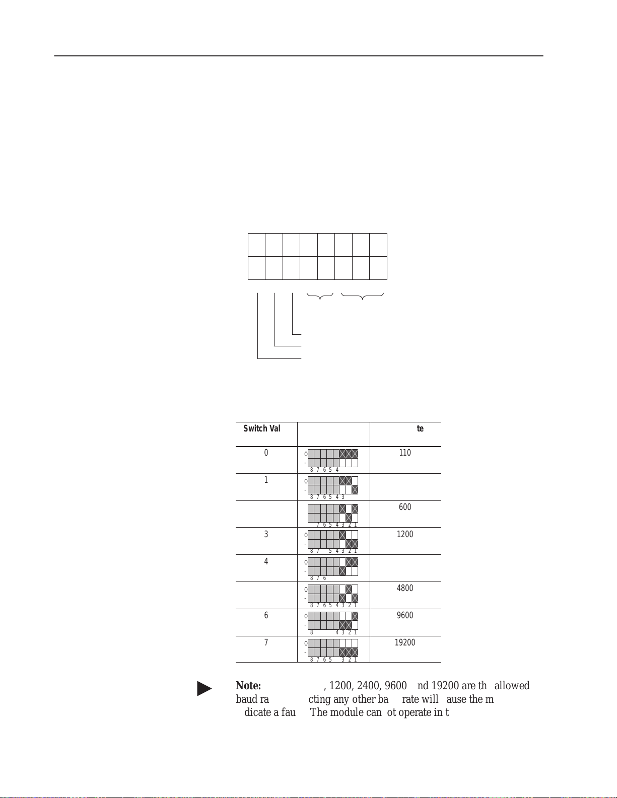
Use SW2–3, SW2–2, and SW2–1 to select the baud rate:
Switch Value
(Decimal)
0
ÁÁÁ
1
ÁÁÁ
2
ÁÁÁ
3
4
ÁÁÁ
5
ÁÁÁ
6
ÁÁÁ
7
SW2
O
ÁÁÁ
–
87 654321
O
–
ÁÁÁ
87 654321
O
–
ÁÁÁ
87 654321
O
–
87 654321
O
ÁÁÁ
–
87 654321
O
–
ÁÁÁ
87 654321
O
–
ÁÁÁ
87 654321
O
–
87 654321
Baud Rate
110
ÁÁÁÁ
300
ÁÁÁÁ
600
ÁÁÁÁ
1200
2400
ÁÁÁÁ
4800
ÁÁÁÁ
9600
ÁÁÁÁ
19200
1203–5.5 September 1995
"
Note: For DH–485, 1200, 2400, 9600, and 19200 are the allowed
baud rates. Selecting any other baud rate will cause the module to
indicate a fault. The module cannot operate in this state.
Page 21
2–7Installation
"
Note: If you are using the DH–485 communications mode, setting
switches SW2–4, SW2–5, SW2–6. SW2–7, and SW2–8 have no
effect because this information is selected within the software.
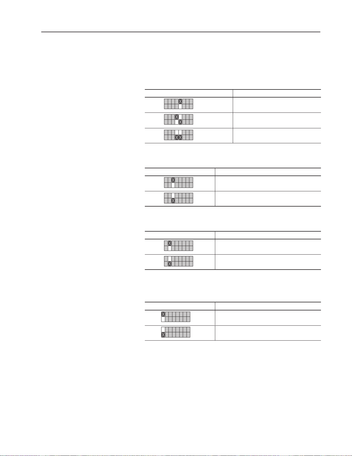
Use SW2–5 and SW2–4 to set the parity:
SW2 Function
O
–
87 654321
O
–
87 654321
O
–
87 654321
Parity disabled
Even parity
Odd parity
Use SW2–6 to choose between 1 stop bit and 2 stop bits:
SW2 Function
O
–
87 654321
O
–
87 654321
1 stop bit
2 stop bits
Use SW2–7 to choose between point–to–point and multi–drop:
SW2 Function
O
–
87 654321
O
–
87 654321
Point–to–point
Multi–drop
Use SW2–8 to choose between BCC checksum mode and CRC
checksum mode:
SW2 Function
O
–
87 654321
O
–
87 654321
BCC Checksum
CRC Checksum
1203–5.5 September 1995
Page 22
2–8 Installation
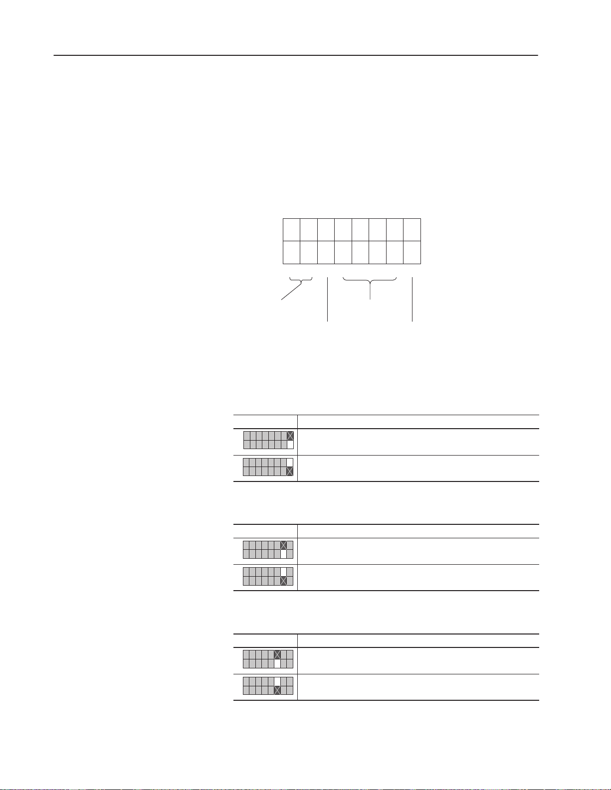
Switch SW3
Switch SW3 is used to select:
• logic command/status and reference/feedback
• datalinks (up to four datalinks)
• duplicate message detection
• application timeout default value
SW3
O
F
F
O
N
8765 43 21
detection
Datalink message
enables
Logic command/
status and reference/
feedback
AB0400B
Application timeout
default values
Duplicate message
Use SW3–1 to enable and disable the logic command/status and
reference/feedback messaging:
SW3 Function
O
–
87 654321
O
–
87 654321
Disable logic command/status and reference/feedback messaging.
Enable logic command/status and reference/feedback messaging.
Use SW3–2 to enable and disable Datalink A messaging:
SW3 Function
O
–
87 654321
O
–
87 654321
Disable Datalink A messaging.
Enable Datalink A messaging.
1203–5.5 September 1995
Use SW3–3 to enable and disable Datalink B messaging:
SW3 Function
O
–
87 654321
O
–
87 654321
Disable Datalink B messaging.
Enable Datalink B messaging.
Page 23

Use SW3–4 to enable and disable Datalink C messaging:
SW3 Function
O
–
87 654321
O
–
87 654321
Disable Datalink C messaging.
Enable Datalink C messaging.
Use SW3–5 to enable and disable Datalink D messaging:
SW3 Function
O
–
87 654321
O
–
87 654321
Disable Datalink D messaging.
Enable Datalink D messaging.
Use SW3–6 to enable and disable duplicate message detection:
SW3 Duplicate Message Detection
O
–
87 654321
O
–
87 654321
Disable duplicate message detection.
Enable duplicate message detection.
2–9Installation
Use SW3–7 and SW3–8 to set the default application timeout value.
The default value is used for application timeout unless the user
writes a value to the application timeout address in the Serial
Communications Module data table. This address is N42:3. If
power is removed, the default value is reloaded during power–up.
SW3 Application Timeout Default Value
O
–
87 654321
O
–
87 654321
O
–
87 654321
O
–
87 654321
No timeout (disabled)
1 second
30 seconds
60 seconds
In DH–485 mode, the application timeout function is as follows:
• If the application timeout is set to zero, the module will not cause
the SCANport device to fault if DH–485 communications are
disrupted.
• If the application timeout is set to a non–zero value, the module
causes the SCANport device to fault if a DH–485 device that had
sent a message to data table N41 drops off the network.
1203–5.5 September 1995
Page 24

2–10 Installation
Mounting the Serial Communications Module
The Serial Communications Module can be provided in three
mounting configurations:
• Open style board, factory installed in a drive (not available for all
drives)
• Open style board as a separate kit
• Enclosed style for panel mount or DIN rail mount
This section provides mounting information for the Open style kit
and the Enclosed style.
Open Style Communications Module Mounting Location (1336 PLUS
7.5–500HP)
1336 PLUS Main Control Board
Human
Interface
Module
Open Serial Communications
Module Mounts Here
U44
Memory
Module
J3
SCANport
Port 6
Mounting screws
& standoffs qty 4
U50 U54 U56
L OPTION
J7
TB2
J4
J9
TB1
AB0404C
1203–5.5 September 1995
Page 25

Enclosed Style Communications Module Mounting Location
(1336 FORCE and 1336 PLUS Drives)
1336 FORCE
ESC SEL
JOG
Port Expander
SCANport 2
2–11Installation
234
5
Communications
Module
Optional
Male–Male
Cable
Communications
Module
1203–5.5 September 1995
Page 26

2–12 Installation
Enclosed Style Serial Communications Module Dimensions
44mm
(1.75)
45mm
(1.8)
Top View
45mm
(1.8)
Enclosed Style Serial Communications Module Dimensions
DIN Rail
DIN Rail
Notes:
– The enclosure requires clearance at the top and bottom
for proper cooling. Additional space is required if you want
to access the DIP switches without removing the device.
– All dimensions are given in millimeters and (inches).
70mm
(2.7)
Back View
DIN Rail
Mounting Clip
DIN Rail
76mm
(3.0)
Front View
25mm
DIN Rail
25mm
(1)
(1)
123mm
(4.8)
DIN
Rail
Side View
AB0406A
1203–5.5 September 1995
Page 27

2–13Installation
Connecting Cables
This section provides information that you need to connect the cables
to your Serial Communications Module.
Important: When connecting your cables, you should make sure
that the network is properly terminated. You should
also ground the shield at the end furthest from the Serial
Communications Module.
1746-BAS Module Serial Connections
Serial Communications Module to 1746-BAS Module
PRT1, PRT2 RS–232 Mode Port Connection Diagram
Communications Module
9-Pin D-Shell
N.C.
N.C.
N.C.
N.C.
1
2
3
4
5
COM
TX
RX
N.C.
COM
6
7
8
9
GND
1746-BAS Module
Port Connection
5
9
4
8
3
7
2
6
1
COM
DTR
TX
RX
N.C.
N.C.
CTS
RTS
DSR
AB0401B
Serial Communications Module to 1746-BAS Module
PRT1, PRT2 RS–422 Mode Port Connection Diagram
Communications Module
9-Pin D-Shell
COM
RXD –
RXD +
N.C.
SHIELD
N.C.
TXD +
TXD –
COM
Serial Communications Module to 1746-BAS Module
PRT1, PRT2 RS–485 Mode Port Connection Diagram
Communications Module
COM
N.C.
N.C.
N.C.
SHIELD
N.C.
TXD/RXD +
TXD/RXD –
COM
1
6
2
7
3
8
4
9
5
9-Pin D-Shell
1
6
2
7
3
8
4
9
5
GND
1746-BAS Module
Port Connection
5
9
4
8
3
7
2
6
1
1746-BAS Module
Port Connection
5
9
4
8
3
7
2
6
1
COM
N.C.
N.C.
RXD –
TXD –
COM
N.C.
N.C.
N.C.
TRXD –
TXD +
N.C.
N.C.
RXD +
AB0402B
TRXD +
N.C.
N.C.
N.C.
GND
AB0403B
1203–5.5 September 1995
Page 28

2–14 Installation
IBM PC Compatible Serial Connections
RS–485/RS–422/RS–232 Communications Adapter to IBM AT
Compatible Computer RS–232 Serial Port Connection Diagram
Communications Module
9-Pin D-Shell
N.C.
N.C.
N.C.
N.C.
1
6
2
7
3
8
4
9
5
COM
TX
RX
N.C.
COM
GND
1747–AIC Link Coupler Serial Connections
Serial Communications Module to 1747–AIC Link Coupler
PRT1, PRT2 DH–485 Mode Port Connection Diagram
Communications Module
9-Pin D-Shell
N.C.
N.C.
N.C.
TRXD–
1
6
2
7
3
8
4
9
5
COM
N.C.
SHIELD
TRXD+
COM
IBM AT Compatible
Personal Computer
RS232 Serial Port
5
9
4
8
3
7
2
1
6
Phoenix 6–Point Connector
1747–AIC Link Coupler
TERM
A
B
COMMON
SHLD
CHS GND
Computer Internal
Jumper Connectors
COM
RI
DTR
CTS
TX
RTS
RX
DSR
DCD
AB0409D
1203–5.5 September 1995
Page 29

PLC5 Channel 0 Serial Connections
Serial Communications Module to PLC5 RS–232
Serial Port Connection Diagram
2–15Installation
PLC5/20, 5/40, 5/60, 5/80
Channel 0
Communications Module
9-Pin D-Shell
N.C.
N.C.
N.C.
N.C.
1
6
2
7
3
8
4
9
5
COM
TX
RX
N.C.
COM
SLC 5/03 Port 1 Serial Connections
Communications Module
9-Pin D-Shell
1
2
3
4
5
6
7
8
9
10
11
12
13
14
15
16
17
18
19
20
21
22
23
24
25
C.GND
TXD
RXD
RTS
CTS
DER
SG.GND
DCD
RES
N.C.
RES
RES
N.C.
N.C.
RES
N.C.
RES
RES
N.C.
DTR
RES
N.C.
N.C.
RES
RES
SLC 5/03 RS–232 Port
AB0486B
COM
TX
RX
N.C.
COM
N.C.
N.C.
N.C.
N.C.
1
6
2
7
3
8
4
9
5
5
9
4
8
3
7
2
1
6
COM
DTR
TX
RX
DCD
N.C.
CTS
RTS
DSR
AB0411B
1203–5.5 September 1995
Page 30

2–16 Installation
SCANport Link Connection
Cable Requirements
SCANport cables are available in either male–to–male or male–to–
female configuration. You can connect cables of up to 10 meters (33
feet) from the master to the SCANport device (A in the figure
below). If you use a Port Expander (as shown in the figure below),
you need to subtract the cable length from the master to the Port
Expander from the cable length used to connect the device to the
expander (B1 + C = a maximum of ten meters).
1305 Drive
An Allen-Bradley SCANport link cable is used to connect the Serial
Communications Module to the drive (as shown below).
SCANport Connection on Serial Communications Module
1305 Drive
Port Expander
Port 2
Port 1
C
234
5
B2
Optional
Male–Male
Cable
Communications
Module
A
Male–Female
Human Interface
Module
Optional
Cable
B1
Communications
Module
Important: The maximum cable distance between any two devices
cannot exceed 10 meters (33 feet) of cable.
For example: A + B1 + C ≤ 10 meters
A + B2 + C ≤ 10 meters
B1 + B2 ≤ 10 meters
AB0407B
1203–5.5 September 1995
Page 31

2–17Installation
1336 PLUS and 1336 FORCE
Refer to the product manual for connection information. On larger
horsepower 1336 PLUS and FORCE drives with an open Serial
Communications Module mounted in the drive, you do not need a
separate SCANport cable connection.
Connection information for the 1336 PLUS and 1336 FORCE is
shown on page 2–11.
Important: The maximum cable distance between any two devices
cannot exceed 10 meters (33 feet) of cable.
1394
Refer to the product manual for connection information.
SMP 3
An Allen-Bradley SCANport cable is used to connect the Serial
Communications Module to an SMP3.
Important: The maximum cable distance between any two devices
cannot exceed 10 meters (33 feet) of cable.
SCANport Connection on Serial Communications Module
SMP3
Connection
Port 1
SMP 3
Port 2
Enclosed
Communications Module
Human Interface
Module
AB0408B
1203–5.5 September 1995
Page 32

2–18 Installation
Power Supply Connections
The Enclosed Communications Module is powered from a separate
24V DC or 115/230V AC power supply (as shown below). With the
Open Style Communications Module board mounted in the drive, no
separate power supply connections are required.
Typical Power Supply Connection
115/230V
Typical
Connection
115V AC Hi
115V AC Low
GND
Communications Module
24V DC
Typical
Connection
L
N
G
Enclosed
24V
DC
Power
Supply
+
_
GND
Communications Module
+
–
G
Enclosed
AB0413B
1203–5.5 September 1995
Page 33

Chapter
SCANport Datalink Operation
3
Chapter Objectives
SCANport Datalinks
In this chapter, you will read about SCANport Datalinks.
A Datalink is a type of pointer function used by some SCANport
devices to transfer parameter values to and from the SCANport
device. The Datalink function transfers parameters on a regular
schedule. Reading a parameter using the Datalink function (data
table N41) requires less time than reading a parameter using the
Parameter Value Read data table addresses (data tables N10 – N19 or
N50 – N89) because the module is kept updated on the parameter
value.
SCANport devices that support this function have a group of
parameters for Datalink configuration. These parameters are
identified as Datalink In and Datalink Out parameters. To enable the
Datalink functions, you need to:
1. Set the correct switch to Enable on SW3 of the Serial
Communications Module.
2. Configure the Datalink In and Datalink Out parameters in the
SCANport device.
Each Datalink consists of two 16-bit words of input and two 16-bit
words of output. You can configure each of the two input words to
write to a different destination parameter within the SCANport
device by setting the two Datalink In parameters for that Datalink to
the desired destination parameters. Similarly, you can configure each
of the two output words by setting the two Datalink Out parameters
for that Datalink.
Each Datalink switch on SW3 can enable or disable one Datalink.
• If a Datalink is enabled, the value of the parameters set into the
Datalink Out parameters is transferred to the Serial
Communications Module and the data sent by the Serial
Communications Module for the Datalink is transferred into the
parameters set into the Datalink In parameters.
• If a Datalink is not enabled, the data transferred to the SCANport
device for that Datalink is zero and the Serial Communications
Module ignores any data sent by the SCANport device.
If no Datalink In parameter is configured for an input word, that
word is ignored. If no Datalink Out parameter is configured for an
output word, the output word is undefined (usually set to zero).
1203–5.5 September 1995
Page 34

3–2 SCANport Data Link Operation
1203–5.5 September 1995
Page 35

Chapter
Configuring and Interfacing
4
Chapter Objectives
Serial Communications Module Data Table Structure
This chapter provides you with information on how the Serial
Communications Module communicates with a serial device. The
following topics are explained:
• Serial Communications Module data table structure
• configuration examples
ATTENTION: When you configure a system for the
first time, you should disconnect the motor from the
!
The Serial Communications Module maintains a data table that
allows the module to communicate with serial devices using standard
PCCC commands.
machine or the process during the initial testing.
1203–5.5 September 1995
Page 36

4–2 Configuring and Interfacing
CMD Code FNC Code Command Name PLC Addressing Method
01h n/a Unprotected read PLC–2 address
06h 00h Echo n/a
01h Read diagnostic counters Variable (modified PLC–2 addresses)
02h Set variables (#ENQs, #NAKs, TIMEOUT) n/a
03h Identify host and some status n/a
04h Set timeout n/a
05h Set #NAKs n/a
06h Set #ENQs n/a
07h Reset diagnostic counters n/a
09h Read link parameters Logical address
0Ah Set link parameters Logical address
Supported PCCC Command List
The Serial Communications Module supports the following PCCC
Commands:
08h n/a Unprotected write PLC–2 address
0Fh 67h Typed write System address (4 possibilities)
68h Typed read System address (4 possibilities)
A1h
A2h
A9h
AAh
ABh
Protected typed logical read with two
address fields
Protected typed logical read with three
address fields
Protected typed logical write with two
address fields
Protected typed logical write with three
address fields
Protected typed logical write with four
address fields
File number/type/element number
File number/type/element
number/sub–element number
File number/type/element number
File number/type/element number/
sub–element number
File number/type/element number/
sub–element number/bit mask
1203–5.5 September 1995
Page 37

Data Table Structure
The Serial Communications Module provides the following data
table structures for DF1 and DH–485.
The following table is the drive control table (binary file).
4–3Configuring and Interfacing
"
File
Address
B3:0 Logic Command B3:10 Logic Status
B3:1 Reference B3:11 Feedback
B3:2 Datalink A1 In (to Drive) B3:12 Datalink A1 Out (from Drive)
B3:3 Datalink A2 In (to Drive) B3:13 Datalink A2 Out (from Drive)
B3:4 Datalink B1 In (to Drive) B3:14 Datalink B1 Out (from Drive)
B3:5 Datalink B2 In (to Drive) B3:15 Datalink B2 Out (from Drive)
B3:6 Datalink C1 In (to Drive) B3:16 Datalink C1 Out (from Drive)
B3:7 Datalink C2 In (to Drive) B3:17 Datalink C2 Out (from Drive)
B3:8 Datalink D1 In (to Drive) B3:18 Datalink D1 Out (from Drive)
B3:9 Datalink D2 In (to Drive) B3:19 Datalink D2 Out (from Drive)
Description
File
Address
Description
Note: If you write to B3:0 through B3:9, you will write data to the
drive. If you read from B3:0 through B3:9, you will return the data
being currently sent to the drive. If you read from B3:10 through
B3:19, you will read data from the drive. If you write to B3:10
through B3:19, you will receive an error.
The following table is the drive control table (integer file).
File Address Description
N41:0 Logic Command/Status
N41:1 Reference/Feedback
N41:2 Datalink A1
N41:3 Datalink A2
N41:4 Datalink B1
N41:5 Datalink B2
N41:6 Datalink C1
N41:7 Datalink C2
N41:8 Datalink D1
N41:9 Datalink D2
"
Note: If you write to any location in N41, you will write data to the
drive. If you read from any location in N41, you will read data from
the drive.
1203–5.5 September 1995
Page 38

4–4 Configuring and Interfacing
Important: The following two tables list the typical control and
status structure. You should refer to your drive manual
for the actual control and status structures for your
device.
The following are the bit definitions for B3:0 or writes to N41:0:
Bit Description Bit Description
00 Stop 10 Acceleration time
01 Start 11 Acceleration time
02 Jog 12 Deceleration time
03 Clear faults 13 Deceleration time
04 Direction 14 Reference select
05 Direction 15 Reference select
06 Local 16 Reference select
07 MOP increment 17 MOP decrement
The following are the bit definitions for B3:10 or reads from N41:0:
Bit Description Bit Description
00 Enabled 10 At speed
01 Running 11 Local
02 Command direction 12 Local
03 Actual direction 13 Local
04 Accelerating 14 Reference select
05 Decelerating 15 Reference select
06 Alarm 16 Reference select
07 Faulted 17 Reference select
1203–5.5 September 1995
Page 39

4–5Configuring and Interfacing
The following is the data table structure for PLC–2 style addressing:
Parameter
Number
1 – 7039
1 – 7039
PLC–2 Style Address
Decimal (Octal)
512 + Parm #
(1000 to 16577)
(16600 to 167770 Status of last parameter write
7680 + Parm #
(17000 to 34577)
(34600 to 34677) Block transfer emulation area
(34700) Logic command/status
(34701) Reference/feedback
(34702) Datalink A1
(34703) Datalink A2
(34704) Datalink B1
(34705) Datalink B2
(34706) Datalink C1
(34707) Datalink C2
(34710) Datalink D1
(34711) Datalink D2
(34712) #ENQs
(34713) #NAKs
(34714) Message TIMEOUT (mS)
(34715) Application TIMEOUT (seconds)
(34716) Adapter series number (2=B)
(34717) Adapter firmware version (201=FRN2.01)
(34720) Maximum node address (DH–485)
(34721 to 37677) Reserved area for future expansion
(37700 to 37777) System area
Description of Location’s Purpose
Parameter value read
Parameter read full
"
Note: The address locations shown in this table are not limited to
PLC–2 commands and may be used by any device that can generate
them.
1203–5.5 September 1995
Page 40

4–6 Configuring and Interfacing
The following is the data table structure for the Serial
Communications Module:
Parameter Number File Addresses Description of Location’s Purpose
1 – 999 N10:1 – 999
1000 – 1999 N11:0 – 999
– – value
8000 – 8999 N18:0 – 999 read or write
9000 – 9999 N19:0 – 999
1 – 249 N50:1 – 249
250 – 499 N51:0 – 249 Parameter
– – value
9500 – 9749 N88:0 – 249 read or write
9750 – 9999 N89:0 – 249
N20:0 – 127 Status of last parameter write
1–999 N30:1 – 999
1000 – 1999 N31:0 – 999 Parameter
– – read
8000 – 8999 N38:0 – 999 full
9000 – 9999 N39:0 – 999
1 – 249 N90:1 – 249
250 – 499 N91:0 – 249 Parameter
– – read
9500 – 9749 N128:0 – 249 full
9750 – 9999 N129:0 – 249
N40:0 – 63 Block transfer emulation area
N41:0 Logic command/status
N42:0 #ENQs
N42:1 #NAKs
N42:2 Message TIMEOUT (mS)
N42:3 Application TIMEOUT (Seconds)
N42:4 Adapter series number (2 = B)
N42:5 Adapter firmware version (201=FRN2.01)
N42:6 Maximum node address (DH–485)
System File 0
(or N200:1 – 63)
SLC compatible system file (DH–485)
Parameter
Station name (DF1)
1203–5.5 September 1995
"
Note: Some devices cannot access an element number over 254.
The files from N50 to N129 are intended for use with those devices.
Page 41

4–7Configuring and Interfacing
The data tables have up to eight areas, each having a different
purpose.
1. Parameter Value Read or Write (N10 – N19, N50 – N89).
Reading data from files in this area will cause the Serial
Communications Module to read parameter values from the
SCANport device and send those values as the response to the
read message. Writing data to files in this area will cause the
Serial Communications Module to write that data into SCANport
device parameters.
2. Status of Last Parameter Write (N20). This area is read-only.
When read, the data returned contains status information from the
last parameter write that was performed by the Serial
Communications Module. If no errors occurred during the write,
all of the data returned will be zeros. Read this area beginning at
element number zero.
3. Parameter Read Full (N30 – N38, N90 – N129). This area is
read-only. When read, the data returned consists of 20 words (40
bytes) of information about each parameter including scaling,
parameter text, units text, minimum, maximum, and default
values. When reading this area, set the number of elements to
twenty times the number of parameters to be read.
4. Block Transfer Emulation Area (N40). This area provides a
method for sending and receiving SCANport messages to and
from the SCANport device. This allows you to perform every
SCANport command the device supports. Chapter 5 provides
information about the block transfer emulation functions
available for use with the Serial Communications Module.
To send a SCANport message, write data into this area beginning
with element number zero. Allow sufficient time for the
SCANport device to respond to the message and then read the
response message from this area beginning with element number
zero.
5. Producer/Consumer Emulation Area (N41). Each element in
this area has a different function. Refer to the DIP switch
configuration tables in Chapter 3 for more information.
– Logic Command/Status. Writing sends a Logic Command
to the drive. Reading supplies the SCANport device Logic
Status. Refer to the manual supplied with the SCANport
device for more information.
– Reference/Feedback. Writing sends a reference to the
SCANport device. Reading supplies feedback from the
SCANport device. The meaning of the reference and
feedback values depend on the type of SCANport device.
1203–5.5 September 1995
Page 42

4–8 Configuring and Interfacing
– Datalink A1. Writing to Datalink A1 sends a value to the
parameter pointed to by the DataIn A1 parameter of the
SCANport device. Reading from Datalink A1 reads the
value of the parameter pointed to by the DataOut A1
parameter of the SCANport device.
– Datalink A2 through Datalink D2 function the same as
Datalink A1.
6. Serial Communications Module Parameters (N42). Each of
the four elements in this area can be read or written and affects
the operation of the Serial Communications Module as follows:
– Number of ENQ’s. The number of ENQ’s sent by the
module before giving up on receiving ACK or NAK. The
default is 3.
– Number of NAK’s. The number of times the module will
resend a message if the response is always NAK. The
default is 3.
– Message Timeout. The number of milliseconds the module
will wait before sending an ENQ. The default is 100mS.
– Application Timeout. The number of seconds the module
will wait between messages before faulting the SCANport
device it is connected to. The default is set by the
configuration DIP switches.
– Adapter Series Number. The series letter of the 1203
Serial Communications Module expressed as a number.
For example, 1=A, 2=B, and so forth.
– Adapter Firmware Version. The firmware version number
of the 1203 Serial Communications Module. For example,
201=FRN2.01, 202=FRN2.02, and so forth.
– Maximum Node Address. When in DH–485 mode, this
parameter sets the maximum node address that the adapter
will attempt to communicate with. The default value is 31
(decimal).
7. Reserved for Future Expansion. If you try a read or write to
any address in this area, the Serial Communications Module will
respond with an error message.
1203–5.5 September 1995
8. System Area. Performing a read from this area will cause the
Serial Communications Module to respond with a 22-character
string. This string is set at power-up to contain the Product Text
String from the SCANport device with /1203 appended to it.
Writing to this area changes the characters contained in the string.
Cycling power returns the string to its original text.
Page 43

Configuration Examples
Ladder rung example for Gx2 manual
Rung 2:0
| I:000 MG20:0 B3 +MSG––––––––––––––––––––+ |
+––] [–––]/[–––[ONS]––––––––––––––––––––––––––––+SEND/RECEIVE MESSAGE +–(EN)–+
| 00 EN 2 |Control block MG20:0+–(DN) |
| | +–(ER) |
| +–––––––––––––––––––––––+ |
Data Table Report
MESSAGE INSTRUCTION DATA MONITOR FOR CONTROL BLOCK MG20:0
Communication Command: PLC–5 TYPED READ
PLC–5 Data Table Address: N30:0 ignore if timed–out: 0 TO
Size in Elements: 50 to be retried: 0 NR
Local/Remote: LOCAL awaiting execution: 0 EW
Remote Station: N/A continuous: 0 CO
Link ID: N/A error: 0 ER
Remote Link Type: N/A message done: 0 DN
Local Node Address: 001 message transmitting: 0 ST
Destination Data Table Address: N10:1 message enabled: 0 EN
Port Number: 00
4–9Configuring and Interfacing
DF1 Messaging with a PLC–5/80 Example
This example reads parameters 1 through 50.
Error Code: 0000 (HEX)
1203–5.5 September 1995
Page 44

4–10 Configuring and Interfacing
Notes:
• I:000/00 is any application–related conditioning logic.
• MG20:0.EN is the enabled status bit from the message block.
• B3/2 is a one-shot that causes the message to be resent each time
the message block completes or errors (as long as I:000/00 is
true).
• The DF1 address of the PLC-5 is the same as its DH+ address (set
by DIP switch SW1 on the PLC-5).
• Refer to Publication 6200–6.4.11, Instruction Set Reference, for
information on the MSG block.
• Refer to Publication 1785–6.6.1, Hardware Installation Manual,
for information on configuring the PLC-5 Channel 0 hardware.
• Refer to Publication 6200–6.4.6, Software Configuration and
Maintenance, for information on configuring the PLC-5 Channel
0 driver.
• Only one message may be active to a Serial Communications
Module at any time. When you write the PLC program, you must
ensure this requirement.
1203–5.5 September 1995
Page 45

DF1 Messaging with a 1746–BAS Module Example
This example accepts a parameter number and a value from a user
terminal and writes the data out to a SCANport–compatible device.
100 REM _____________________________________________________________
101 REM __ This program inputs a parameter number and a value
102 rem __ from a user terminal and writes it out to a scanport
103 rem __ compatible device.
104 rem __ for 1746–BAS and 1203–GD2 modules
105 rem _____________________________________________________________
110 STRING 512,127
140 REM
150 REM ––––––––––––––––––––––––––––––––––––––––––––––––––––––––––––––
160 REM Setup port 1 to 9600 baud, no parity, 8 bits, 1 stop bit,
170 REM software handshaking, and battery backed ram data storage.
180 REM !!!!REMEMBER TO SET TERMINAL TO MATCH!!!!
190 REM ––––––––––––––––––––––––––––––––––––––––––––––––––––––––––––––
200 MODE (PRT1,9600,N,8,1,S,R)
210 REM ––––––––––––––––––––––––––––––––––––––––––––––––––––––––––––––
220 REM
230 REM Setup port 2 to 300 baud, no parity, 8 bits, 1 stop bit,
240 REM software handshaking, and battery backed ram data storage.
250 REM
260 REM ––––––––––––––––––––––––––––––––––––––––––––––––––––––––––––––
270 MODE (PRT2,300,N,8,1,S,R)
280 REM ––––––––––––––––––––––––––––––––––––––––––––––––––––––––––––––
290 REM
300 REM Enable DF1 driver
310 REM (20 = Setup for Full Duplex, Auto–Detect Embedded Responses,
320 REM Disable Duplicate Packet Detection, BCC error checking)
330 REM (200 = Wait 1 second for polling by Master)
340 REM (2 = 2 retries)
350 REM (0= No RTS on delay)
360 REM (0 = No RTS off delay)
370 REM (8 = 1746–BAS module address)
380 REM ––––––––––––––––––––––––––––––––––––––––––––––––––––––––––––––
390 PUSH 20
400 PUSH 200
410 PUSH 2
420 PUSH 0
430 PUSH 0
440 PUSH 8
450 CALL 108
460 REM __________________ end df1 config _____________________________
461 Print: print ”A negative parameter number exits the program ”
470 INPUT ”Offset (Parameter Number)? ”,PAR_NUM
475 IF (PAR_NUM<0) THEN GOTO 530
480 INPUT ”Control (parameter value)? ”,PAR_VALUE
481 REM encode the value as an ASCII hex string in order of LOW, HIGH
490 ASC($(1),1)=PAR_VALUE–(INT(PAR_VALUE/256)*256)
500 ASC($(1),2)=INT(PAR_VALUE/256)
510 GOSUB 550 : REM fire off the write instruction
520 GOTO 460
530 CALL 113
540 END
4–11Configuring and Interfacing
1203–5.5 September 1995
Page 46

4–12 Configuring and Interfacing
550 REM ****************************************************************
560 REM ********* PLC TYPED READ Subroutine *****
561 REM ********* inputs Parameter number in var PAR_NUM *****
562 REM ********* ASC coded hex string of value in $(1) *****
563 REM ********* outputs: failure message *****
565 REM ****************************************************************
570 REM subroutine to do a typed write of a single parameter
580 PRINT ”Executing PLC Remote Write ”
600 PUSH 5 : REM PLC5 Typed Write
610 PUSH 1 : REM Communications Module Node Address
620 PUSH 10 : REM File Number ( atterss is N10:PAR_NUM)
630 PUSH ASC(N) : REM Communications Module File Type
640 PUSH PAR_NUM : REM Starting Word in File
650 PUSH 1 : REM Number of Words to Transfer (one parameter)
660 PUSH 50 : REM Command Time–out (x100ms)
670 PUSH 2 : REM Data Source (2 = Internal String)
680 PUSH 0 : REM Offset in M0 file (Not used in this example)
690 PUSH 1 : REM String # ASCII hex number order low, high
700 CALL 123 : REM Builds the message to be sent
710 POP S
720 PUSH 123 : REM sets up call 29
730 CALL 29 : REM send the message
750 RETURN
760 REM *********** End Write parameter subroutine *********
1203–5.5 September 1995
Page 47

4–13Configuring and Interfacing
DH–485 Messaging with a SLC5/03 Interface
The following example uses the DH–485 communications mode to
send a message from an SLC5/03 to the Serial Communications
Module.
Rung 2:0
If this is the first scan or the error bit is true, the MSG instruction’s control
byte is cleared and the done bit is set. This ensures that the program always
starts correctly and recovers from a MSG error.
| First |
| Scan |
| Bit |
| S:1 +AND–––––––––––––––+ |
|–+––––] [–––––+––––––––––––––––––––––––––––––––––––––+–+BITWISE AND +–+–|
| | 15 | | |Source A 255| | |
| | | | | | | |
| | | | |Source B N15:0| | |
| | | | | 8192| | |
| | | | |Dest N15:0| | |
| | | | | 8192| | |
| | | | +––––––––––––––––––+ | |
| | MSG Block | | MSG Block | |
| | Error (ER) | | Done (DN) | |
| | Bit | | Bit | |
| | N15:0 | | N15:0 | |
| +––––] [–––––+ +––––(L)–––––––––––––––+ |
| 12 13 |
Rung 2:1
When the MSG instruction is done, the TON provides a 2 second delay before another
message is sent. B3:0/0 represents user logic. The timer can be adjusted to
provide control over DH485 network loading.
| User |MSG Block |
| DH485 |Done (DN) |
| Enable |Bit |
| B3:0 N15:0 +TON–––––––––––––––+ |
|––––] [––––––––] [––––––––––––––––––––––––––––––––––+TIMER ON DELAY +–(EN)–|
| 0 13 |Timer T4:0+–(DN) |
| |Time Base 0.01| |
| |Preset 200| |
| |Accum 156| |
| +––––––––––––––––––+ |
1203–5.5 September 1995
Page 48

4–14 Configuring and Interfacing
Rung 2:2
When the timer is done, the MSG instruction is enabled.
| TON Done – |
| Enable |
| MSG Block |
| T4:0 +MSG––––––––––––––––––––+ |
|––––] [––––––––––––––––––––––––––––––––––––––––+READ/WRITE MESSAGE +–(EN)–|
| DN |Type PEER–TO–PEER+–(DN) |
| |Read/Write WRITE+–(ER) |
| |Target Device 500CPU| |
| |Local/Remote LOCAL| |
| |Control Block N15:0| |
| |Control Block Length 14| |
| +–––––––––––––––––––––––+ |
Rung 2:3
| |
|–––––––––––––––––––––––––––––––––––––+END+––––––––––––––––––––––––––––––––––––|
| |
Address Data (Radix=BINARY) Address Data (Radix=BINARY)
B3:0 0000 0000 0000 0001
The following are the data tables used for this example:
Address EN TT DN TIME BASE PRE ACC
T4:0 1 1 0 .01 sec. 200 156
Address CU CD DN OV UN UA PRE ACC
C5:0 0 0 0 0 0 0 32767 2778
Address Data (Radix=DECIMAL)
N10:0 7 6 0 0 0 0 0 0 0
Address Data (Radix=DECIMAL)
N15:0 8192 3 9 10 137 5 0 224 10 0
N15:10 0 0 0 0
M0:1 File Length:64
M0:2 File Length:0
M0:3 File Length:0
M0:4 File Length:0
M1:1 File Length:64
M1:2 File Length:0
M1:3 File Length:0
M1:4 File Length:0
1203–5.5 September 1995
Page 49

Block Transfer Emulation
Instructions
Chapter
5
Chapter Objectives
Block Transfer Emulation Status Word
This chapter contains the header and data configurations that you
need to set up the data files for the block transfer emulation
instructions. The header and data values depend on the operation
you want to perform.
When an operation is unsuccessful, header word 2 of the drive
response contains a negative value (bit 15 = 1).
In most cases, the drive also returns a status word to indicate the
reason for the failure. The location of the status word is typically
header word 4 in the drive response, but will depend on the message.
The following are valid status codes:
Value Description
0 No error occurred.
The service failed due to an internal reason, and the drive could not perform
1
the request (some messages are read only or write only).
2 The requested service is not supported.
3 An invalid value in the block transfer emulation request header word 2.
4 An invalid value in the block transfer emulation request header word 3.
5 An invalid value in the block transfer emulation request header word 2.
6 The data value is out of range.
There is a drive state conflict. The drive is in an incorrect state to perform the
7
function. The drive cannot be running when you perform certain functions.
1203–5.5 September 1995
Page 50

5–2
Scattered Parameter Value Read
The Scattered Parameter Value Read function reads a scattered list of
parameters.
PLC Block Transfer Emulation Instruction Data
PLC request instruction length: 5–63 words
Drive response instruction length: 5–63 words
Message Structure
PLC Request
Message Length
5–63
PLC Decimal Value
3
Number of Parameter
Values to Read
Parameter Number
1
0
Parameter Number
Parameter Number
2
0
Parameter Number
3
0
•
•
•
•
•
•
30
0
Header Word 1
Header Word 2
Data Word 3
Data Word 4
Data Word 5
Data Word 6
Data Word 7
Data Word 8
Data Word 9
•
•
•
•
•
•
Data Word 62
Data Word 63
Drive Response
Message Length
5 – 63
PLC Decimal Value
3 –– Message OK
–32765 –– Message Error
Number of Parameter
Values to Read
bit
Parameter Number
15
1
Parameter Value or
Status Word
1
Parameter Number
bit
15
2
Parameter Value or
Status Word
2
bit
Parameter Number
15
3
Parameter Value or
Status Word
3
•
•
•
•
•
•
Parameter Number
bit
15
30
Parameter Value or
Status Word
30
Header
Word 1
Header
Word 2
Data
Word 3
Data
Word 4
Data
Word 5
Data
Word 6
Data
Word 7
Data
Word 8
Data
Word 9
•
•
•
•
•
•
Data
Word 62
Data
Word 63
1203–5.5 September 1995
Page 51

5–3Block Transfer Emulation Instructions
Message Operation
Scattered Parameter Value Read reads a pre–defined group of
parameter values, in any order, from the device. You define the
number of parameters to read in word 3 of the request. The
parameters to be read and their order is defined starting with word 4.
An unused word is left between each parameter request, so the drive
can respond with the parameter value, as shown.
If an error has occurred in reading any of the parameters:
• Word 2 of the drive response returns a value of –32765.
• Bit 15 of the drive response word for the number of that
parameter is set.
• The drive response word for the value of that parameter returns a
status word instead of returning the parameter value.
Example
PLC request
Drive response
In this example, eight parameters were read from a 1336 PLUS
drive, as defined in word 3 of the request. The parameter numbers
requested were 5, 7, 8, 20, 18, 17, 19, and 36. The drive response
returned the values of these parameters in the data file. These values
are in drive units.
Data File Format
0
N10:10
N10:20
N10:90
N10:100
19 3
0 18*
19 3
* Example only – These values vary depending on parameters and products.
123456 78 9
8*
0* 17*
8*
4096*4096* 18*
5*
5*
17*
0 7* 0 8* 0
0
6*
51*
19*
7*
19*
0
1000*
60*
36*
8*
36*
0
1000*
6144*
20*
20*
1203–5.5 September 1995
Page 52

5–4
Scattered Parameter Value Write
The Scattered Parameter Value Write function writes to a scattered
list of parameters and returns the status of each parameter. If any of
the states have errors, the parameter number is negative.
PLC Block Transfer Emulation Instruction Data
PLC request instruction length: 5–63 words
Drive response instruction length: 5–63 words
Message Structure
PLC Request
Message Length
5–63
PLC Decimal Value
–32765
Number of Parameter
Values to Write
Parameter Number
1
Parameter Value
1
Parameter Number
Parameter Number
2
Parameter Value
2
Parameter Number
3
Parameter Value
3
•
•
•
•
•
•
30
Parameter Value
30
Header Word 1
Header Word 2
Data Word 3
Data Word 4
Data Word 5
Data Word 6
Data Word 7
Data Word 8
Data Word 9
•
•
•
•
•
•
Data Word 62
Data Word 63
Drive Response
Message Length
5 – 63
PLC Decimal Value
3 –– Message OK
–32765 –– Message Error
Number of Parameter
Values to Write
bit
Parameter Number
15
Status Word 1
bit
15
Status Word 2
bit
15
Status Word 3
bit
15
Status Word 30
1
Parameter Number
2
Parameter Number
3
•
•
•
•
•
•
Parameter Number
30
Header
Word 1
Header
Word 2
Data
Word 3
Data
Word 4
Data
Word 5
Data
Word 6
Data
Word 7
Data
Word 8
Data
Word 9
•
•
•
•
•
•
Data
Word 62
Data
Word 63
1203–5.5 September 1995
Page 53

5–5Block Transfer Emulation Instructions
Message Operation
The Scattered Parameter Value Write function writes data values to a
pre–defined group of device parameters in any order. You define the
number of parameters to write in word 3. The parameters to be
written to and their order is defined starting with word 4.
If an error occurs while writing to any of the parameters:
• Word 2 of the drive response returns a value of –32765.
• Bit 15 of the drive response word for that parameter’s number is
set.
• The drive response word for that parameter’s status word is
non–zero.
If no error has occurred:
• Word 2 of the drive response returns a value of 3.
• Each of the drive response’s parameter numbers are the same as
in the request.
• Each of the drive response status words returns a value of 0.
PLC request
Drive response
Example
In this example, six parameters were written to in a 1336 PLUS
drive. Word 3 of the request (N10:12) defines the number of
parameter values that are transferred. Each parameter number
followed by its value, are listed in the message beginning with word
4. The values are entered in device units.
The drive response (N10:90) returns the status of each parameter
write. If the request was successful, a zero is returned. If an error
has occurred, the response returns a status word code for the error.
Data File Format
0
N10:0
N10:20
N10:90
N10:100
* Example only – These values vary depending on parameters and products.
15 –32765 6*
10* 10* 2* 12*
15 3 6*
0* 10* 0*
123456789
90*
90*
12*
0*
1*
150* 4* 30* 20*
5*
0*
150* 0* 30* 0*
31*
31*
1203–5.5 September 1995
Page 54

5–6
Product ID Number Read
The Product ID Number Read function returns the product ID of the
device to which the Serial Communications Module is connected.
PLC Block Transfer Emulation Instruction Data
PLC request instruction length: 3 words
Drive response instruction length: 4 words
Message Structure
PLC Request
Message Length
3
PLC Decimal Value
256
0
Header Word 1
Header Word 2
Data Word 3
Drive Response
Message Length
6
PLC Decimal Value
256 –– Message OK
–32512 –– Message Error
0
Product ID Number
Header
Word 1
Header
Word 2
Header
Word 3
Data
Word 4
Product ID
Number
2
3
4
5
16
17
18
19
20
21
22
23
Description
1336F (PLUS Fractional)
1336F (PLUS)
1336G (FIBERS Fractional)
1336G (FIBERS)
1336T (FORCE)
1395
1394
1557
SMP
SMC
1304
1305
Message Operation
The Product ID Number Read function, through the drive response
message word 4, indicates the type of device the Serial
Communications Module is connected to. This value is defined in
the message response chart shown above.
If an error has occurred, word 2 of the response returns a negative
value of –32512.
1203–5.5 September 1995
Page 55

Example
In this example, the Product ID Number Read was requested. The
drive response contained a value of 3 in word 4 of its message
response, indicating a connection to a 1336 PLUS.
Data File Format
5–7Block Transfer Emulation Instructions
PLC request
Drive response
N10:0
N10:90
0
30
60
123456789
256
256
3*
* Example only – These values vary depending on parameters and products.
1203–5.5 September 1995
Page 56

5–8
Parameter Read Full
The Parameter Read Full function provides all known attributes for
the parameters requested. This information includes the parameter’s
current value, descriptor, multiply and divide value, base value,
offset value, text string, group element reference, minimum value,
maximum value, default value, and unit text string.
PLC Block Transfer Emulation Instruction Data
PLC request instruction length: 3 words
Drive response instruction length: 20 words
Message Structure
PLC Request
Message Length
3
PLC Decimal Value
768
Parameter Number
(See Drive List)
Header Word 1
Header Word 2
Data Word 3
Drive Response
Parameter Value
or Status Word
Descriptor
Multiply Value
Data
Word 1
Data
Word 2
Data
Word 3
Divide Value
Base Value
Offset Value
Parameter Text
Char 2 Char 1
Parameter Text
Char 4 Char 3
Parameter Text
Char 6 Char 5
Parameter Text
Char 8 Char 7
Parameter Text
Char 10 Char 9
Parameter Text
Char 12 Char 11
Parameter Text
Char 14 Char 13
Parameter Text
Char 16 Char 15
Data
Word 4
Data
Word 5
Data
Word 6
Data
Word 7
Data
Word 8
Data
Word 9
Data
Word 10
Data
Word 11
Data
Word 12
Data
Word 13
Data
Word 14
1203–5.5 September 1995
Page 57

Message Structure (Continued)
5–9Block Transfer Emulation Instructions
Drive Response
File, Group, Element
Minimum Value
Maximum Value
Default Value
Unit Text
Char 2 Char 1
Unit Text
Char 4 Char 3
Data
Word 15
Data
Word 16
Data
Word 17
Data
Word 18
Data
Word 19
Data
Word 20
Message Operation
Parameter Read Full retrieves the attributes of the specified
parameter. The attributes for each parameter include the data,
minimum and maximum values, and the parameter text. The
response message returns this information.
If an error has occurred in reading any of the values, word 1 contains
the status word.
The parameter text is returned with each data word containing two
ASCII characters per word. The first and second characters are in
opposite order.
Example
In this example, a Parameter Read Full was performed through block
transfer on a 1336 PLUS. N10:10 shows the header message for the
request. The data is returned in the response data file, starting with
word 1, for parameter 20. Word 1 shows the present value in drive
units. Word 2 through word 6 provide scaling information, used to
convert drive units to engineering units for the Human Interface
Module (HIM). Word 7 through word 14 provide the parameter
name.
1203–5.5 September 1995
Page 58

5–10
This example shows the response message N10:90 through N10:112
in both binary and ASCII. Note the ASCII information beginning
with N10:99. The parameter name characters return in reverse order
for each word. N10:99 has the ASCII value of (aM). To read this,
invert the word to read (Ma). The next word (ix), inverted gives you
(xi). These words, along with the following two words, form the
word Maximum. You can see the parameter name Maximum Voltage
in word 7 through word 14 of the response message. In addition,
word 20, is also returned in this format. This word provides the units
the parameter is defined in. In this example it is vlts.
Word 15 contains the file, group, and element which are used to
reference the parameter.
Words 16–18 contain the minimum, maximum, and default values of
this parameter.
Data File Format
PLC request
Drive response
Drive response
N10:10
N10:90
N10:100
N10:90
N10:100
0
3 768 20*
4096* 355* 1* 4096*
28502* 29804* 26465* 8293*
#
\10\00
#
o V
12 3 45 6 7 8 9
460*
1794*0*1024*
\01 c
t l g a e 07 02 04 00 \13 0
\00\01 \01\CC \00\00 a M i x u m\10\00 m
24909*
4915*
* Example only – These values vary depending on parameters and products.
# ASCII Display values
27000*
4096*
\10\00
30061*
27734* 29556*
l V s t
8301*
1203–5.5 September 1995
Page 59

5–11Block Transfer Emulation Instructions
Parameter Value Read
The Parameter Value Read function reads the 16–bit parameter data
value for the selected parameter number.
PLC Block Transfer Emulation Instruction Data
PLC request instruction length: 3 words
Drive response instruction length: 1 word
Message Structure
PLC Request
Message Length
3
PLC Decimal Value
769
Parameter Number
(See Drive List)
Message Operation
Header Word 1
Header Word 2
Header Word 3
Drive Response
Parameter Value or
Status Word
Data
Word 1
PLC request
Drive response
N10:10
N10:90
Parameter Value Read reads parameter values from the drive and
places that value (or an error code) in word 1 of the drive response
data file. The value is shown in device units. Device units are listed
in the user manual for the device you are using.
If an error occurs:
• Word 1 of the response contains the status code.
• The status area of the data file is non–zero.
Example
In this example, the value of parameter 20 was requested from a
1336 PLUS and a value of 4096 was returned. 4096 is the internal
drive unit value for the Maximum Rated Voltage Parameter. This
corresponds to a value of 100% Drive Rated Volts in Display Units.
Data File Format
0
3 769 20*
4096*
1234 5678 9
* Example only – These values vary depending on parameters and products.
1203–5.5 September 1995
Page 60

5–12
Parameter Value Write
The Parameter Value Write message writes a 16–bit parameter data
value to the selected parameter number.
PLC Block Transfer Emulation Instruction Data
PLC request instruction length: 1 word
Drive response instruction length: 4 words
Message Structure
PLC Request
Parameter Value
Data Word 1
Drive Response
Message Length
4
PLC Decimal Value
769 –– Message OK
–31999 –– Message Error
Parameter Number
Status Word
Header
Word 1
Header
Word 2
Data
Word 3
Data
Word 4
PLC request
Drive response
N10:0
N10:90
Message Operation
The Parameter Value Write function sends a new value to the
specified parameter. The value must be in device units. Units for
each parameter are listed in the device manual.
If an error has occurred, word 2 of the response returns a value of
–31999, and word 4 contains a status code.
Example
In this example, a value of 4096 was sent to Parameter 20. 4096 is
in drive units and indicates a value of 100% Drive Rated Volts, as
defined in P147, Drive Rated Volts.
Data File Format
0
4 –31999 20*
4 769 20* 0
123456789
4096*
* Example only – These values vary depending on parameters and products.
1203–5.5 September 1995
Page 61

5–13Block Transfer Emulation Instructions
EE Memory Functions
The EE Memory Functions message activates the specified EE
functions.
PLC Block Transfer Emulation Instruction Data
PLC request instruction length: 4 words
Drive response instruction length: 3 words
Message Structure
PLC Request
Message Length
4
PLC Decimal Value
–31998
0
Value EE Command
00
01
02
03
Not Used
EE Save
EE Recall
EE Default Initialize
Header Word 1
Header Word 2
Header Word 3
Header Word 4EE Command
Drive Response
Message Length
3
PLC Decimal Value
770 –– Message OK
–31998 –– Message Error
0
Header
Word 1
Header
Word 2
Header
Word 3
Message Operation
The EE memory function allows three different message requests:
• EE Save saves parameter information from the working memory
or RAM to EEPROM.
• EE Recall retrieves the last saved data from EEPROM and places
it in the working memory or RAM.
• EE Default Initialize clears the RAM and EEPROM and sets all
parameter values to default.
If an error has occurred, word 2 of the response returns a value of
–31998.
1203–5.5 September 1995
Page 62

5–14
Example
This example requests that an EEPROM Save function be
performed.
Data File Format
PLC request
Drive response
N10:10
N10:90
0
43–31998
1234 5678 9
770
0*
0*
1*
* Example only – These values vary depending on parameters and products.
1203–5.5 September 1995
Page 63

5–15Block Transfer Emulation Instructions
Fault Clear/Reset
The Fault Clear/Reset message activates the Clear Fault, Clear Fault
Queue, and Drive Reset functions.
PLC Block Transfer Emulation Instruction Data
PLC request instruction length: 4 words
Drive response instruction length: 4 words
Message Structure
PLC Request
Message Length
4
PLC Decimal Value
–30976
0
Value Fault Command
00
01
02
03
Not Used
Clear Fault
Clear Fault Queue
Drive Reset (1336 FORCE Only)
Header Word 1
Header Word 2
Header Word 3
Data Word 4Fault Command
Drive Response
Message Length
4
PLC Decimal Value
1792 –– Message OK
–30976 –– Message Error
0
Status Word
Header
Word 1
Header
Word 2
Data
Word 3
Data
Word 4
PLC request
Drive response
Message Operation
The specified fault Clear/Reset function sends a fault handling
request to the device.
• A Clear Fault request clears the last fault that occurred.
• A Clear Fault Queue clears the entire fault buffer. Certain
devices may store more than one fault.
• A Drive Reset is used with the 1336 FORCE drive product only.
This function resets the drive; it clears the fault queue and writes
the parameter information stored in EEPROM to RAM.
Data File Format
0
N10:0
N90:0
4 –30976
4 1792 0*0
* Example only – These values vary depending on parameters and products.
123456789
1,2,30
1203–5.5 September 1995
Page 64

5–16
Fault Queue Entry Read Full
This function reads the contents of the specified fault queue entry. A
message is returned which includes the fault text and fault code
associated with the specified fault queue entry. The 1336 FORCE
also returns the time stamp associated with the fault.
PLC Block Transfer Emulation Instruction Data
PLC request instruction length: 3 words
Drive response instruction length: 12 or 16 words
Message Structure
PLC Request
Message Length
3
PLC Decimal Value
1792
Fault Queue
Entry Number
Header Word 1
Header Word 2
Data Word 3
Drive Response
Message Length
18
PLC Decimal Value
1792 –– Message OK
–30976 –– Message Error
Fault Queue
Entry Number
Fault Text
Char 2 Char 1
Fault Text
Char 4 Char 3
Fault Text
Char 6 Char 5
Fault Text
Char 8 Char 7
Fault Text
Char 10 Char 9
Fault Text
Char 12 Char 11
Fault Text
Char 14 Char 13
Fault Text
Char 16 Char 15
Header
Word 1
Header
Word 2
Header
Word 3
Data
Word 4
Data
Word 5
Data
Word 6
Data
Word 7
Data
Word 8
Data
Word 9
Data
Word 10
Data
Word 11
1203–5.5 September 1995
1336 FORCE
Drive Only
Fault Code Value
Clock Time
SES REF
Clock Time
Hour Minute
Clock Time
Date Day
Clock Time
Y ear Month
Data
Word 12
Data
Word 13
Data
Word 14
Data
Word 15
Data
Word 16
Page 65

5–17Block Transfer Emulation Instructions
Message Operation
Fault Queue Entry Read Full reads the contents of the fault queue
specified in word 3 of the request. The response returns the fault text
which can be ASCII text. The text will have every two characters in
reverse order. In addition, the 1336 FORCE returns a time stamp,
indicating the day and time the fault occurred.
If an error has occurred, word 2 of the response returns a negative
value.
Example
In this example, Fault Queue Entry number 3 was retrieved from a
1336 PLUS drive. The drive response returned the ASCII text Drive
Reset Flt, with each character reversed. The fault code for this
example is 22.
Data File Format
PLC request
Drive response
N10:0
N10:90
N10:100
N10:90
N10:100
0
3 1792 3*
18 1792 3* 29252*
8308*
#
\00\12
#
t \00\16
123456789
30313* 8293* 25938* 25971* 8308*
22*
\07\00
\03\00 v i l F
r D
e
e R
* Example only – These values vary depending on parameters and products.
# ASCII Display values
27718*
e s t
1203–5.5 September 1995
Page 66

5–18
Fault Queue Size
The Fault Queue Size function gets the number of fault entries
allowed in the fault queue.
PLC Block Transfer Emulation Instruction Data
PLC request instruction length: 3 words
Drive response instruction length: 4 words
Message Structure
PLC Request
Message Length
3
PLC Decimal Value
1793
0
Header Word 1
Header Word 2
Header Word 3
Drive Response
Message Length
5
PLC Decimal Value
1793 –– Message OK
–30975 –– Message Error
0
Fault Queue Size
Header
Word 1
Header
Word 2
Data
Word 3
Data
Word 4
PLC request
Drive response
Message Operation
The Fault Queue Size function reads back the size of the fault queue
available in the product. Each product may have a different number
of fault queue entries available for storage.
If an error has occurred, word 2 of the response returns a value of
–30975.
Example
In this example, a 1336 PLUS was used. This product has a fault
queue of four storage locations available to store faults. This value
is seen in word 4 of the response header message.
Data File Format
0
N10:0
N10:90
3 1793 0
6 1793 0 4*
* Example only – These values vary depending on parameters and products.
123456789
1203–5.5 September 1995
Page 67

5–19Block Transfer Emulation Instructions
Trip Fault Queue Number
The Trip Fault Queue Number provides the fault queue number of
the fault that caused the device to trip.
PLC Block Transfer Emulation Instruction Data
PLC request instruction length: 3 words
Drive response instruction length: 4 words
Message Structure
PLC Request
Message Length
3
PLC Decimal Value
1794
0
Header Word 1
Header Word 2
Header Word 3
Drive Response
Message Length
4
PLC Decimal Value
1794 –– Message OK
–30984 –– Message Error
0
Number of Trip Fault
Header
Word 1
Header
Word 2
Header
Word 3
Header
Word 4
PLC request
Drive response
Message Operation
The Trip Fault Queue Number function provides the number of the
entry in the fault queue that tripped the device in word 4 of the drive
response. The Fault Queue Number is 0 when the device is not
faulted.
If an error has occurred in the block transfer, word 2 of the response
is negative.
Example
In this example, the device has stored a fault in the first entry of the
Fault Queue that caused the drive to trip. Word 4 of the response
indicates the entry number.
Data File Format
0
N10:0
N10:90
3 1794 0
6 1794 0 1*
* Example only – These values vary depending on parameters and products.
123456789
1203–5.5 September 1995
Page 68

5–20
1203–5.5 September 1995
Page 69

T roubleshooting
Chapter
6
Chapter Objectives
Use this chapter to help you troubleshoot your Serial
Communications Module system using the LED indicators on the
front of the device (as shown below). The Serial Communications
Module is a non-serviceable device that you should return to
Allen-Bradley for replacement when a major fault exists that is
attributable to the Serial Communications Module itself.
LED Locations
Front View Open Version
TX
Serial STS
SCANport STS
RX
J2
Front View Enclosed Version
SW1SW2SW3
J4
RX
SCANport STS
Serial STS
TX
1203–5.5 September 1995
AB0414C
Page 70

6–2 Troubleshooting
Indicator Color Description Recommended Action
Serial Sts Green (blinking) Link OK, off–line
SCANport Sts Green (blinking) Link OK, not connected
TX Off No transmission occurring
RX Off No transmission received
ATTENTION: Servicing energized industrial control
equipment can be hazardous. Electrical shock, burns,
!
or unintentional actuation of controlled industrial
equipment may cause death or serious injury. Follow
the safety-related practices of NFPA 70E, Electrical
Safety for Employee Workplaces, when working on or
near energized equipment. Do not work alone on
energized equipment.
ATTENTION: Do not attempt to defeat or override
fault circuits. You must determine and correct the
!
cause of a fault indication before attempting operation.
Failure to correct a drive or system malfunction may
result in personal injury and/or equipment damage due
to uncontrolled machine system operation.
LED Troubleshooting Table
•Check configuration switch settings.
•Check for serial cable connection.
•Cycle Serial Communications Module power .
Green (steady) Link OK, on–line None, system functioning properly
Red (blinking)
Red (steady) Faulted
Green (steady) Link OK, connected None
Red (blinking)
Red (steady) Faulted
Flash Transmission occurring None
Flash Characters being received None
Link was on–line and is now
off–line
Link was connected and is now
not connected
Check for failed devices or link problems.
•Check configuration switch settings.
•Check for serial cable connection.
•Cycle power , replace module.
•Check configuration switch settings.
•Check for serial cable connection.
•Cycle power .
Check for failed devices or link problems.
•Check configuration switch settings.
•Check for serial cable connection.
•Cycle power , replace module.
•Send serial data again
•Check data device to verify it is sending data
1203–5.5 September 1995
Page 71

Specifications
Chapter
7
Chapter Objectives
Catalog Number: –GM2 –GD2 –GK2
Environmental:
Operating Temperature
Storage Temperature
Electrical:
Input Voltage Supplied by drive 85 to 264V AC, 1 phase
Input Frequency NA 45 to 63 Hz NA
Input Current NA 35mA maximum 0.4 amps maximum
SCANport Load 60mA DC 60mA DC 60mA DC
Communications:
SCANport Side
Serial Side
Baud Rates
Checksum BCC or CRC BCC or CRC BCC or CRC
Dimensions:
This chapter provides you with background information and
specifications that you may need to install or apply your Serial
Communications Module.
Product Specifications
Open Style
0 to 50° C (32 to 122°F) 0 to 50° C (32 to 122°F) 0 to 50° C (32 to 122°F)
–40 to 85° C (–40 to 185°F) –40 to 85° C (–40 to 185°F) –40 to 85° C (–40 to 185°F)
SCANport Peripheral
Interface
RS–232/RS–422/RS–485
(DF1)
DH–485
110, 300, 600, 1200, 2400,
4800, 9600, 19.2K
Open (IP00) NEMA Type 1 (IP30) NEMA Type 1 (IP30)
NA
Enclosed Style 115/230V
AC
SCANport Peripheral
Interface
RS–232/RS–422/RS–485
(DF1)
DH–485
110, 300, 600, 1200, 2400,
4800, 9600, 19.2K
45w x 76h x 123d mm
(1.8 x 3.0 x 4.8 in.)
Enclosed Style 24V DC
24V DC, ±10%
SCANport Peripheral
Interface
RS–232/RS–422/RS–485
(DF1)
DH–485
110, 300, 600, 1200, 2400,
4800, 9600, 19.2K
45w x 76h x 123d mm
(1.8 x 3.0 x 4.8 in.)
Module Compatibility
This module is intended for use with devices that communicate via
RS–232, RS–422, or RS–485 hardware standards using the DF1
protocol or the DH–485 standard. The Serial Communications
Module is intended to provide a means for transmitting messages
between these serial communications devices and Allen-Bradley
SCANport devices.
1203–5.5 September 1995
Page 72

7–2 Specifications
1203–5.5 September 1995
Page 73

Allen-Bradley, a Rockwell Automation Business, has been helping its customers improve
productivity and quality for more than 90 years. We design, manufacture and support a broad
range of automation products worldwide. They include logic processors, power and motion
control devices, operator interfaces, sensors and a variety of software. Rockwell is one of the
worlds leading technology companies.
Worldwide representation.
Argentina • Australia • Austria • Bahrain • Belgium • Brazil • Bulgaria • Canada • Chile • China, PRC • Colombia • Costa Rica • Croatia • Cyprus • Czech Republic •
Denmark • Ecuador • Egypt • El Salvador • Finland • France • Germany • Greece • Guatemala • Honduras • Hong Kong • Hungary • Iceland • India • Indonesia •
Ireland • Israel • Italy • Jamaica • Japan • Jordan • Korea • Kuwait • Lebanon • Malaysia • Mexico • Netherlands • New Zealand • Norway • Pakistan • Peru •
Philippines • Poland • Portugal • Puerto Rico • Qatar • Romania • Russia–CIS • Saudi Arabia • Singapore • Slovakia • Slovenia • South Africa, Republic • Spain •
Sweden • Switzerland • Taiwan • Thailand • Turkey • United Arab Emirates • United Kingdom • United States • Uruguay • Venezuela • Yugoslavia
Allen-Bradley Headquarters, 1201 South Second Street, Milwaukee, WI 53204 USA, Tel: (1) 414 382-2000 Fax: (1) 414 382-4444
1203–5.5 September 1995 74001–014–01(C)
T emplate revised June 23,
1995
1203–5.5 September 1995
Copyright 1995 Allen-Bradley Company, Inc. Printed in USA
 Loading...