

Page 1
DPI Screw Terminal Cable Adapter Kits
Items Included with each Kit
Installation Instructions
Catalog # 1202-CBL-KIT-100M
Qty. Item Description Qty. Item Description
2 8-pin MiniDIN-to-Screw Terminal Adapter 2 8-pin MiniDIN-to-Screw Terminal Adapter
1 Mini-screwdriver (fits screw terminals) 1 Installation Instructions (this sheet)
1 Wire Strip Tool (for stripping 26 AWG wire ends) NOTE: The Adapter-Only Kit is provided so additional cable
100 m Cable (26 AWG x 4 twisted and shielded pairs)
1 Installation Instructions (this sheet)
Important: When using the Adapter-Only Kit (Catalog # 1202-TB-KIT-SET), we have tested and recommend using a cable sold by
Quabbin (p/n 2906), or equivalent. The Quabbin cable is an equivalent to the cable supplied in the Full Kit (Catalog # 1202CBL-KIT-100M) except that it has different wire pair colors (see Tab le 1
Full Kit
assemblies can be made with the 100 meter cable supplied
in the Full Kit. It can also be used by customers that already
have the tools and purchase their cable separately.
Adapter-Only Kit
Catalog # 1202-TB-KIT-SET
on back page) and a foil shield.
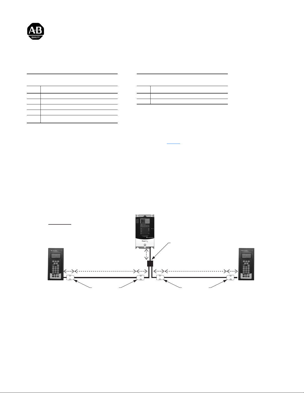
DPI Cable Requirements/Recommendations
1. The maximum cable distance between a DPI peripheral and DPI host is:
• 75 meters with 500 kbps DPI data rate
• 100 meters with 125 kbps DPI data rate
2. The maximum DPI cable length is the SUM of all connected cables between the drive and peripherals(s). This includes all cables
connected via the DPI Screw Terminal cable, 1203-S03 splitter cable, and 1203-SG2/1203-SG4 expander modules.
Example
DPI @ 125 kbps
1203-S03
Splitter Cable
0.3 m
49.25 m
20-HIM-C3S
20-HIM-C5S
20-HIM-B1
3. The installer must follow common system wiring practices and route cables away from sources of EMI, such as drive input power and
motor cables.
Screw Terminal
Cable Adapter
Cable Length Calculations:
•
(1) 1203-S03 + (4) Screw Terminal Cable Adapters = 1.5 m (5 x 0.3 m)
•
100 m maximum - 1.5 m = 98.5 m additional cable length allowed
•
98.5 m ÷ 2 peripherals = 49.25 m each if equi-distant lengths are desired (not required)
0.3 m0.3 m
0.3 m
49.25 m
Screw Terminal
Cable Adapter
0.3 m
20-HIM-C3S
20-HIM-C5S
20-HIM-B1
Page 2
Cable Connections
approx. 0.3 m (12 in.)
P3 P6
P1
P2
P4
P5
1. At one end of the connecting cable, strip back the cable jacket 30 mm (1.18 in.) to expose the shield and twisted wire pairs. Then strip
back the cable’s shield 24 mm (0.94 in.) to expose the twisted wire pairs. Remove 4 mm (0.16 in.) of insulation from the wires of each
twisted pair. Then connect the stripped wires of each twisted pair to their corresponding terminals shown in Tab le 1
Table 1: Cable Wire Connections
P8
P7
Male Connector
56
78
1
234
(Cable Shield Clamp)
A
Connecting Cable
(6.2 mm opening in adapter housing)
(Cable Strain Relief Clamp)
B
:
(Adapter
Mounting
C
Holes)
Integral Cable of Terminal Adapter Connecting Cable Wire Colors
Twisted Pair
Twisted Pair
Twisted Pair
Twisted Pair
(1)
Quabbin Cable
White/Green
White/Orange
Brown
White/Blue
MiniDIN Plug Connected to . . .
Pin 1 Terminal 1 Black
Pin 6 Terminal 2 Green Green
Pin 3 Terminal 3 Red
Pin 4 Terminal 4 Orange Orange
Pin 5 Terminal 7 Yellow
Pin 8 Terminal 8 White White/Brown
Pin 2 Terminal 6 Brown
Pin 7 Terminal 5 Blue Blue
Shell Shield clamp (A) Shield — Shield —
(1)
Twisted pair wire colors for the 100 meter cable supplied with the Full Kit (Catalog # 1202-CBL-KIT-100M).
(2)
Twisted pair wire colors for the Quabbin cable (p/n 2906) that is recommended when using the Adapter-Only Kit (Catalog # 1202-TB-KIT-SET).
Cable in Full Kit
(2)
Twi s t e d P a i r
Twi s t e d P a i r
Twi s t e d P a i r
Twi s t e d P a i r
Important: Cable wire colors are subject to change at any time. If the connecting cable wire colors are different than those listed above,
make sure that each twisted pair is terminated to the same terminal numbers on both ends of the cable.
2. Make sure that the connecting cable’s shield is tightly secured under the cable shield clamp (A). If a foil shield is used (Quabbin cable),
the blue side of the foil shield is non-conductive. In this case, fold back the foil to expose the silver side of the foil to the shield clamp
before installing.
3. Tightly secure the connecting cable’s outer jacket under the cable strain relief clamp (B).
4. The terminal adapter’s two mounting holes (C) can be used to secure the adapter to a flat surface. Use #8 screws (not supplied) of an
appropriate length for the application.
5. Connect the other end of the connecting cable to the second terminal adapter. Repeat steps 1 through 4.
Publication 1202-IN001B-EN-P – May 2004 P/N 319926-P02
Supersedes 1202-IN001A-EN-P, September 2003 Copyright © 2004 Rockwell Automation. All rights reserved. Printed in China.
 Loading...