

Roadstar HIF-5811MPT Service Manual

Service Manual
- HIF-5811MPT
R
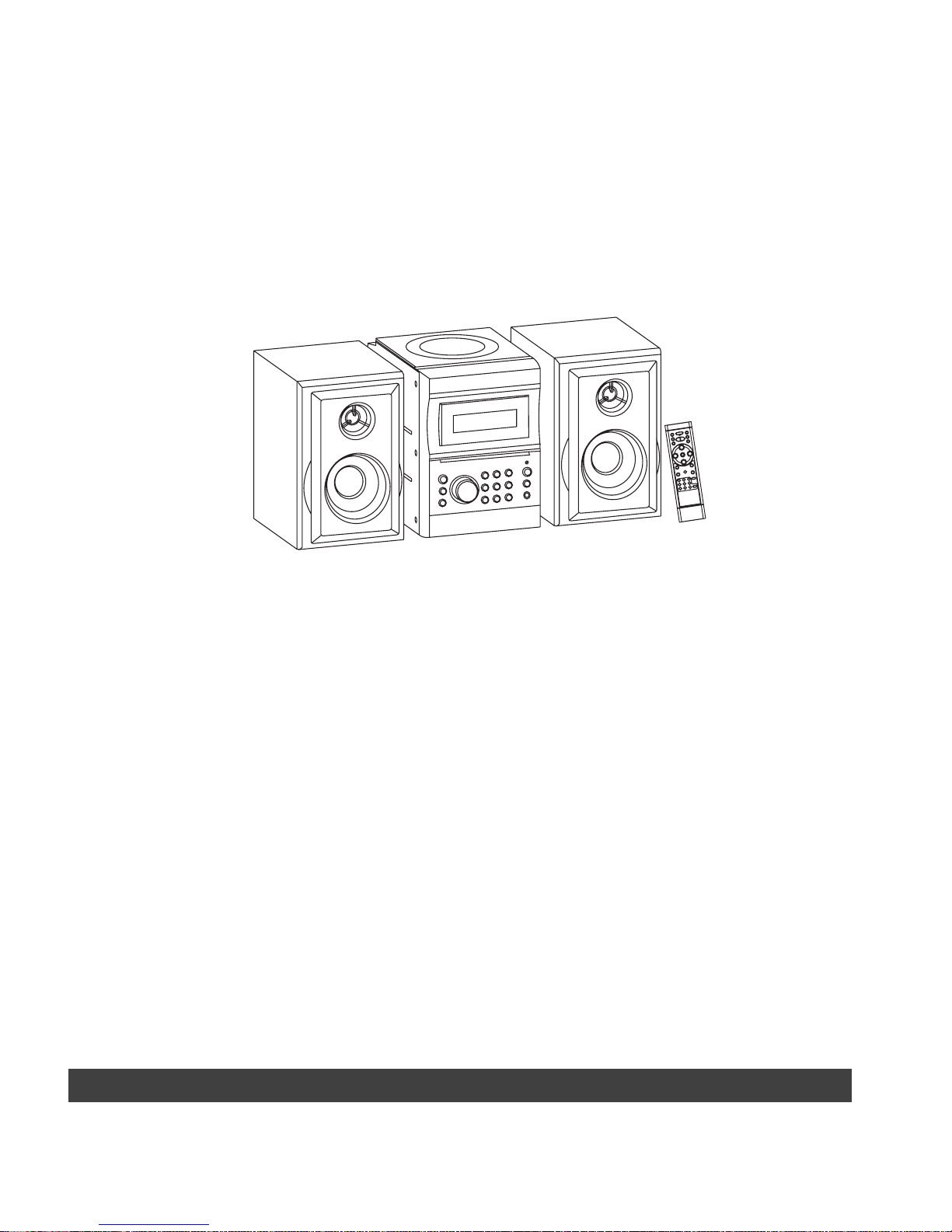
HIF-5811MPT
Service Manual
- HIF-5811MPT

NOTE: All the specifications and features are subject to change without notice.
SERVICE PUBLICATION
AM/FM TUNER SECTION
ANTENNASYSTEM
FM: LEAD WIRE AND 75 OHM JACK
TUNING RANGE
FM: 87.5- 108 MHz
AUDIO SECTION
SPEAKER IMPEDANCE : 4 OHM
GENERAL : 5W x2
POWER INPUT : ~AC 230V-50Hz
AC POWER CONSUMPTION
MAIN DIM : 267.5(L) (H)mmx152(W)x218.5
WEIGHT : 5.49Kg
AM: 522 -1620 kHz
AM: FERRITE BAR
SPEAKER DIM : 140 mm(L)x215(W)x218.5(H)
PORTABLE RADIO CASSETTE WITH CD/MP3 PLAYER
CAUTION: Beforeservicing the chassis,readthe " importantservice safety information"
section onpage 2 ofthismanual.
SPECIFICATIONS CONTENTS
DISASSEMBLY INSTRUCTIONS--------------------- 3
ADJUSTMENTLOCATIONS----------------------------4
ALIGNMENTPROCEDURES-----------------------5 -11
IC BLOCK DIAGRAMS----------------------------15- 19
VOLTAGECHARTS--------------------------------12 - 14
BLOCK DIAGRAM---------------------------------------20
WIRING DIAGRAM-------------------------------------21
PRINTED CIRCUIT BOARDS---------------------29 -32
SCHEMATICDIAGRAMS-------------------------22 - 28
EXPLODED VIEW/PARTSLIST(CABINET)---33 - 35
IMPORTANT SERVICE SAFETY INFORMATION---2

2
IMPORTANT SERVICE SAFETY INFORMATION
ANTENNA
TERMINAL
OHMMETER
OM
EXPOSED
METAL
PART
TEST ALL
EXPOSED METAL
SURFACES
(READING SHOULD
NOTBEABOVE
0.5mA)
LEAKAGE
CURRENT
TESTER
EARTH
GROUND
DEVICE
UNDER
TEST
2-WIRE CORD
ALSO TESTWITH
PLUG REVERSED
(USING ACADAPTER
PLUG ASREQUIRED)
AC LEAKAGETEST
2. PRODUCT SAFETY NOTICE
some electrical and mechanical parts have special safety
related characteristics which are often not evident from
visual inspection. Nor can the protection they give
necessarily be obtained by replacing them with
components rated for higher voltage , wattage, etc. Parts
that have special safety characteristics are identified by
a on schematic and parts list. Use of a substitute
replacement that dose not have the same safety
characteristics as the recommended replacement part
might create shock, fire, and/or other hazards. Product
safety is under review continuously and new instructions are
issued whenever Appropriate.
3. Servicing precautions
CAUTION: before servicing the unit covered by this service
by this service manual and its supplements. Read and follow
the SAFETY PRECAUTIONS on this page.
NOTE: if unforeseen circumstances create a conflict
between the following servicing precautions and any of the
Safety precautions, always follow the safety precautions.
Remember: safety first.
General servicing precautions.
a. Always unplug the unit s AC power cord from the AC
power source Before:
(1)removing or reinstalling any component, circuit board,
module or any other unit assembly.
(2)disconnecting or reconnecting any unit electrical plug or
other Electrical connection.
(3)connecting a test substitute in parallel with an electrical
capacitor caution: a wrong part substitution or incorrect
polarity installation Of electrolytic capacitors may result in
an explosion hazard
b. Do not defeat any plug/socket b+ voltage interlocks with
which the unit covered by this service manual might be
equipped.
c. Do not apply AC power to this unit and/or any its electrical
assemblies unless all solid-state device heat sinks are
correctly installed.
d. Always connect a test unit instrument s ground lead to
the unit s chassis ground before connecting the test
instrument s positive lead always remove the test
instrument s ground lead last.
CAUTION: USE OF CONTROLS, ADJUSTMENTS OR
PERFORMANCE OF PROCEDURES HEREIN MAY
RESULT IN HAZARDOUS RADIATION
EXPOSURE.
DANGER: IF INTERLOCK FAILS OR IS DEFEATED, THE LASER
LIGHT IS ABLE TO FUNCTION. THE LASER IS
INVISIBLE, AVOID DIRECT EXPOSURE TO BEAM.
4. Laser precautions
Warning!
(1)When servicing.(Incase it isnecessary to confirm laser
Beam emission ) besure not toplace your eyesany
closer than1or 30cm from thesurface of the objective
lens on the optical pickup block.
HANDLING THE LASERPICKUP
( 2)Laser Diodesare Extremely Susceptibleto damage from
static electricity even ifa static dischargedies not ruin
the diode, itcan shorten its lifeor cause itto work
improperly.When replacing the pickup, use a conductive
maton the floorand desk andwear a wrist band
connected to groundthrough a 1Mohm resistor
to protect the laserdiode from staticdamage. If the lens
should get dusty, blow off thedust carefully fromthe
object.
(3)There areno adjustable parts in the pickupassembly. If it
is defective, replace the wholepickup assembly.
1. SAFETY PRECAUTIONS
Before returning a unit to the customer, always make a safety
check of the entire unit, including, but not limited to the
following items:
a. Be sure that no built-in protective devices are defective
and/or have been defeated during servicing.
(1)protective shields are provided to protect both the
technician and the customer. Correctly replace all
missing protective shields including any removed for
servicing convenience.
(2)when reinstalling the chassis and/or other assemblies in
the cabinet, be sure to put back in place all protective
devices, including , but not limited to , nonmetallic
control knobs, insulating fishpapers. adjustment and
compartment covers/shields and isolating resistor/
capacitor networks. Do not operate this or permit it to be
operated Without all protective devices correctly
installed and functioning .
b. Be sure that there are no cabinet openings through which
an adult or child might be able to insert their fingers and
contact a hazardous voltage. Such openings include, but
are not limited to, excessively wide cabinet ventilation
slots, and an improperly fitted and/or incorrectly secured
cabinet back cover.
c. Leakage current hot check - with the unit completely
reassembled ,plug the AC line cord directly into a 120V
AC outlet. (Do not use an isolation transformer during this
test.) Use a leakage current tester or a metering system
that complies with American National standards Institute
(ANSI) C101.1 Leakage Current for Appliances and
Underwriters Laboratories(UL) 1410 (50.7). WITH THE
UNIT AC switch first in the ON position And then in the
OFF position, measure from a known earth ground (metal
water pipe, conduit, etc.) To all exposed metal parts of
the Unit (antennas, handle bracket, metal cabinet, screw
heads , metallic overlays, control shaft, etc.) Especially
any exposed metal parts that offer an electrical return
path to the chassis. Any current measured must not
exceed 0.5 milliamp, reverse the unit power cord plug in
the outlet and repeat test .
ANY MEASUREMENTS NOT WITHIN THE LIMITS
SPECIFIED HERENING INDICATE A POTENTIAL SHOCK
HAZARD THAT MUST BE ELIMINATED
RETURNING THE
UNIT TO THE CUSTOMER.
d. Insulation resistance test cold check:
unplug the power supply cord and connect a jumper wire
between the two prongs of the plug .
Turn on the power switch of the unit.
Measure the resistance with an ohmmeter between
jumpered AC PLUG AND EACH Exposed metallic cabinet
part on the unit, such as screw heads, antenna, control
shafts, handle brackets, etc. When the exposed metallic
part has a return path to the chassis , the reading should
be between 1 and 5.2 megohms. When there is no return
path to the chassis, the reading must be infinite If it is
not within the limits specified, there is the possibility of a
shock hazard, and the unit must be repaired and
rechecked before it is returned to the customer.
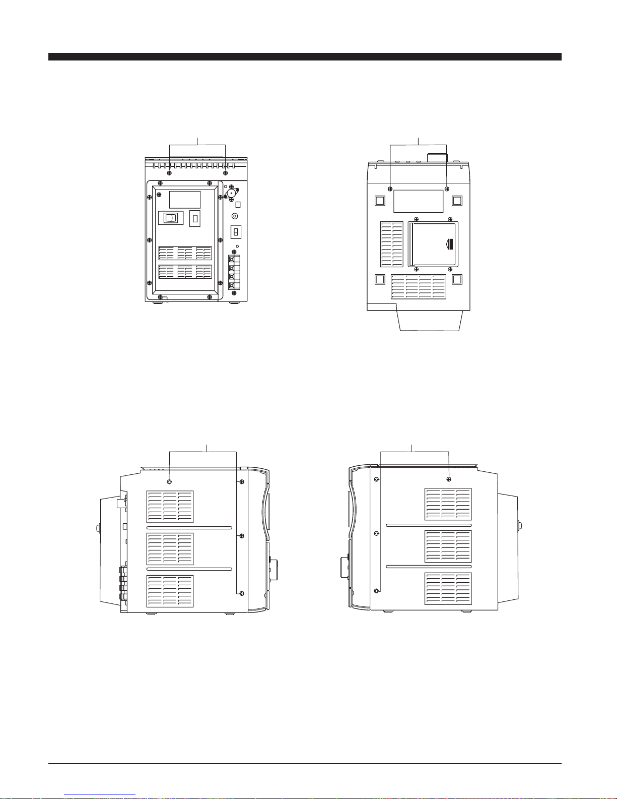
DISASSEMBLY INSTRUCTIONS
3
3X10KA 3X10KA
3X10PA 3X10PA
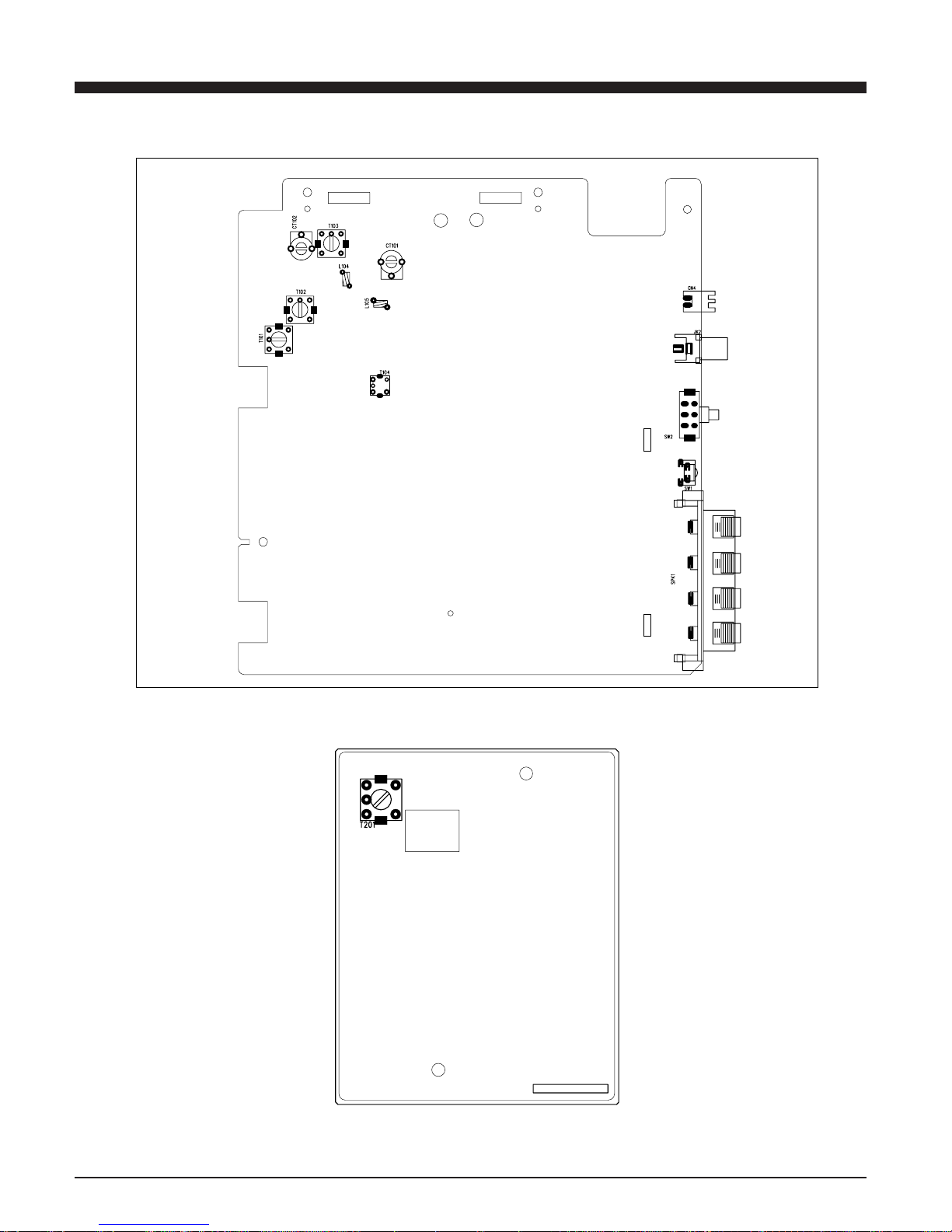
ADJUSTMENTLOCATIONS
4
ALIGNMENT PROCEDURES
5
FM AND AM RF ALIGNMENT CHART ( IF )
Step item Input Circuit Output Circuit Tuner Adj - Adjustment
Setup Setup setting Point
Unless otherwise specified set switches as follows:
FM Function: FM
Adjust generator frequency to a center of the FM band where no FM broadcast exists
IF Connect FM IF Connect Co19 and GND FM in band Adjust for straight and
1 Adjustment sweep output IF-OUT terminal to end T104 symmetrical S-curve
terminal to IC102 IF sweep input terminal with max.amplitude.
2 FM Headphone jack or 87.5 MHz L105 Adjust L103 for max output
Band setup speaker terminal 108MHz Done
FM SG ANT. Headphone jack or 90.1 MHZ L104 Adjust for max.output and
3 Tracking (1) Terminal 90.1 MHz, speaker terminal MONO best waveform
1kHz, +-22.5kHz dev
4 Tracking (2) 106.1 MHz, 1 kHz Headphone jack or 106.1 MHz CT101 Same as above.
+-22.5 MHz dev speaker terminal
5 Repeat steps 3 and 4.
MW
IF Connect standard loop Connect input terminal MW in band Adjust tor max. amplitude
1 Adjustment antenna to output ter- genescope to detector end T101 with symmetrical 450 kHz.
minal of genescope output
2 MW Headphone jack or 522 kHz T102 Adjust L135 for max output
Band speaker terminal 1620 kHz CT103 Adjust CT133 for max output
3 Tracking (1) 612 kHz 400 kHz, Headphone jack or 612 kHz T103 Adjust for max.output and
3% mod speaker terminal best waveform
4 Tracking (2) 1404 kHz 400 kHz, Headphone jack or 1404 kHz CT102 Same as above.
3% mod speaker terminal
5 Repeat steps 3 and 4.
TAPE SECTION
HEAD ADJUSTMENT (AZIMUTH)
10 kHz test tape (example:MTT-114N) must be used for this adjustment. Connect to VTVM or oscilloscope to the headphone JCK or speaker terminal Press the play button.
Adjust the azimuth by using a screw driver to maintain the maximum L & R output voltage. Adjust tape. Please secure the
azimuth position by using locking paint.
RECODING BIAS OSCILLATOR FREQUENCY ADJUSTMENT
Connect the frequency counter to of R601 two ends.
Press REC button of tape .
Adjust T201 obtain 60 kHz +-100 HZ
ALIGNMENT PROCEDURES
6
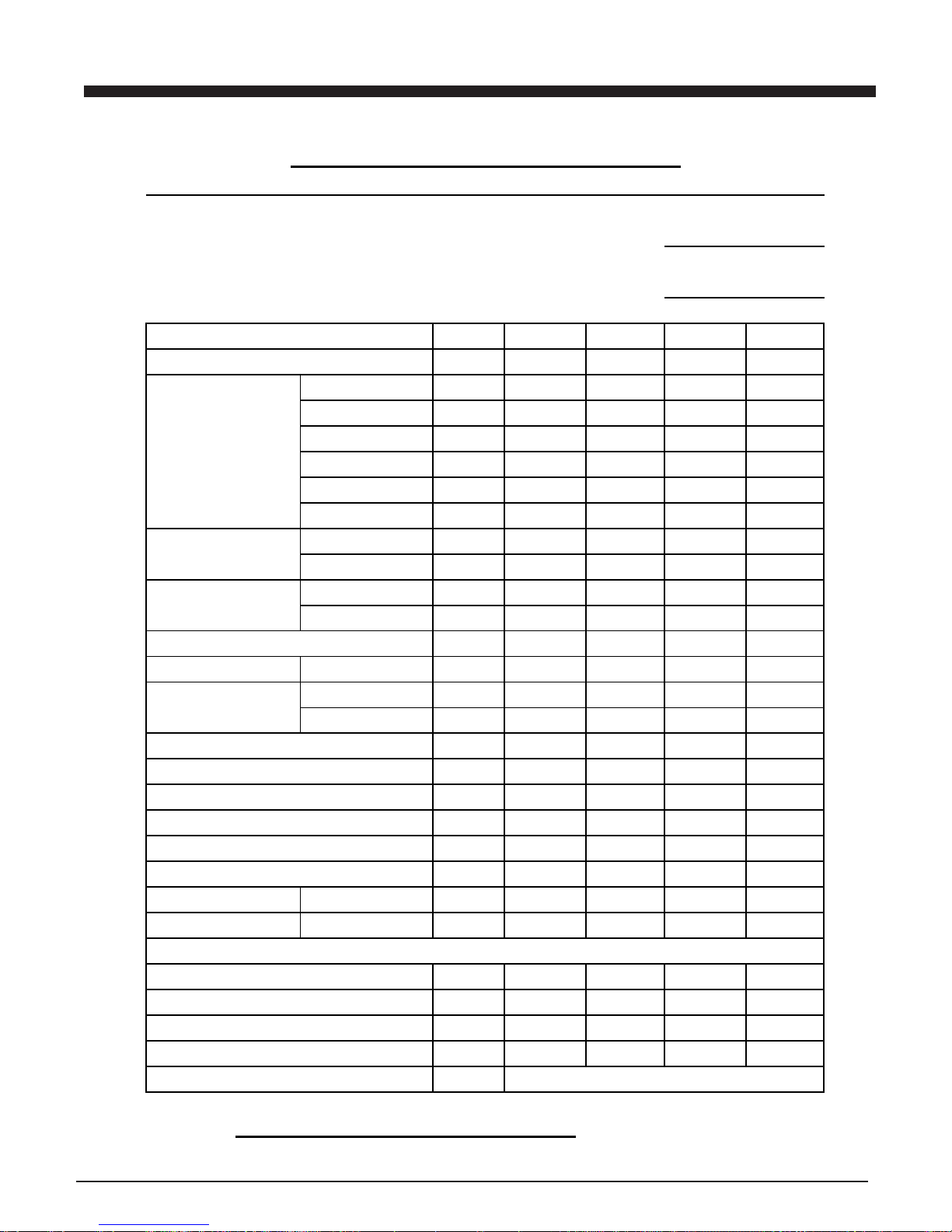
FM RECEIVER PERFORMANCE DATA
Band: FM BRAND: QUELSS
Supply Voltage: AC 230 V Measured By:
Standard Output: 50 mw
Dummy Load: 4 ohm Approved By:
Modulation: 1 KHz 22.5 KHZ DEV
EQ or Tone at Flat Place Bass OFF Place
Measuring Items Unite Norm Limit Sample1 Sample2
Frequency Range Low MHz 87.5 +/-0.3
High MHz 108 +/-0.3
IF Frequency MHz 10.7 +/-0.2
30db Quieting 90.1 MHz db 18 26
Sensitivity 98.1 MHz db 18 26
106.1 MHz db 18 26
Auto Locked 90.1 MHz db 26 32
Sensitivity 98.1 MHz db 26 32
106.1 MHz db 26 32
ACA +300 KHz db 20 15
( 2-Signal ) -300 KHz db 20 15
Image Rejection AT 106.1 MHz db 22 16
IF Rejection AT 90.1 MHz db 50 40
-3db Limiting Sens . 1mv I/P db 18 26
AM Suppression 1mv I/P db 35 30
S/N (1mv input) Mono db 45 40
Stereo db 35 30
Stereo Sens db 20 26
Stereo Lamp On Sens. db 20 26
Separation R/L db 25 20
Audio Freq. Low Hz 80 ≦100
Response-3db High KHz 5 ≧3
Modulation Hum 1 mv I/P db 40 35
Hum & Noise(min.vol.) mv 1 3
Output (10% Dist) (MOD=40KHz) mW 4500 4000
Total Harmonic Distortion 1 mv I/P % 1 3
OSC Drop Out 1 mv I/P V
Current No signal mA
Consumption Max mA
ALIGNMENT PROCEDURES
7
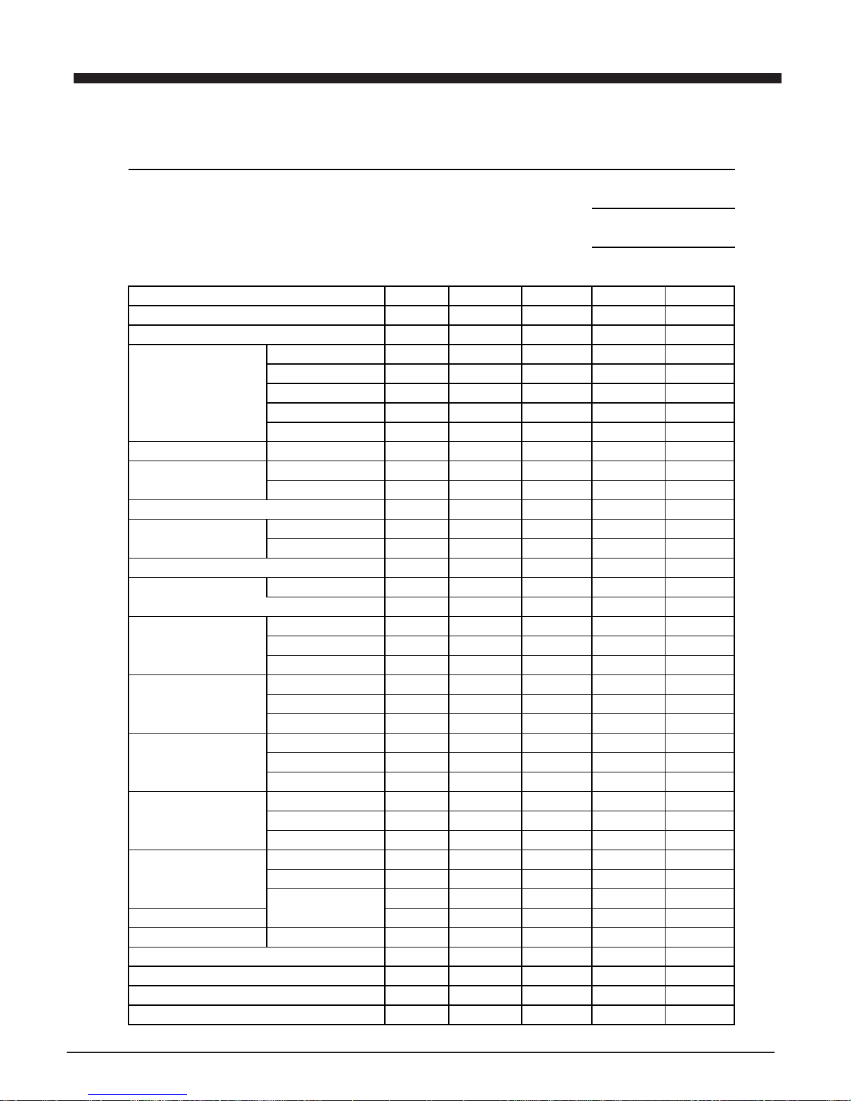
MW RECEIVER PERFORMANCE DATA
Band: MW
Supply Voltage: AC 230 V Measured By:
Standard Output: 50 mw
Dummy Load: 4 Ohm Approved By:
Modulation: 1 KHz 30%
EQ or Tone at Flat Place Bass OFF Place
Measuring Items Unite Norm Limit Sample1 Sample2
Frequency Range Low KHz 522 +/-10
High KHz 1620 +/-10
IF Frequency KHz 450 +/-2
20db Quieting 612 KHz dB/M 60 66
Sensitivity 999 KHz dB/M 60 66
1404 KHz dB/M 60 66
Auto Locked 612 KHz dB/M 66 70
Sensitivity 999 KHz dB/M 66 70
1404 KHz dB/M 66 70
S/N 5mv/M dB 35 30
ACA +9 KHz dB 18 12
-9 KHz dB 18 12
Band Width-6dB +Side KHz 3 10
-Side KHz 3 10
Image Rejection AT 1404 KHz dB 35 30
IF Rejection AT 612 KHz dB 50 40
Spuerious Response 4-10MHz dB 40 35
10-30MHz dB 50 45
AGC FOM-10db 100mv/M dB 45 35
Audio Freq. Low Hz 80 ≦100
Response-6db High KHz 2.4 ≧2.0
Modulation Hum 100 mv/M dB 38 32
Hum (Volume At Min) mv 1 3
Output (10% Dist) (MOD=80%) mW 4500 4000
Total Harmonic Distortion 5mv/M % 2 4
OSC Drop Out 5mv/M V
Current No signal mA
Consumption Max mA
ALIGNMENT PROCEDURES
8
CASSETTE PLAYBACK PERFORMANCE DATA
Supply Voltage: AC 230 V
Standard Output: 50 mw Measured By:
Dummy Load: 4 Ohm
0DB=1V Approved By:
EQ or Tone at Flat Place Bass OFF Place
Tape Speed 4.76cm/sec.1 7/
8
I n
Measuring Items Unite Norm Limit Sample1 Sample2
Tape Speed Enor at 3 KHz % +3/-2
WOW & Flutter at 3 KHz % 0.25 0.35
Play Freq Response at 125 Hz dB +/-3 +/-6
at 1 KHz dB 0 0
at 10 KHz dB +/-3 +/-6
P/B S/N (1K odB) DC Opetation dB
AC Optetaion dB 45 40
Hum & Noise Min Vol mv 1 3
(AC Optetaion) Max Vol mv 20 30
10% THD Output (1KHz odB) RMS mw 4500 4000
THD 1KHz -10dB % 1 2
Track Crosstalk dB 40 30
Channel Separation R-L dB 40 30
L-R dB 40 30
Channel Balance -10dB 1KHz dB 1 3
No Signal Current Min. Vol. Blank Tape mA
Max Output Max. Vol A
Play Torque g/cm
F.F Torque g/cm
Rew Torque g/cm
Time for Play Min
Time for F.F Sec
Time for Rew Sec
ALIGNMENT PROCEDURES
9
Measuring Items Unite Norm Limit Sample1 Sample2
Rec Blas System AC KH z 55 60
Erasing System Magnet 6PA
Erasing Ratio dB 38 33
ALC Compresion Time for 20db dB
Stansatding up for -20db at 90% Sec
Recovery time for -20db at 90% Sec
R/P Frep Response at 100 Hz dB +/-3 +/-6
REC CD(-20dB) at 1 KHz dB 0 +/-3
at 10 KHz dB +/-3 +/-6
R/P S/N Built Mic dB
FM 1mv/in dB 38 33
R/P THD at -10dB 1KHz % 5 10
R/P Channal Separatio L-R dB 40 30
(1KHB 0dB) R-L dB 40 30
Record Level Tape = -10dB dB 0 0
CD 1KHz -20dB dB +/-2 +/-4
Radio FM 1KHz 12.5KHz dB +/-2 +/-4
Remote Control Sensitivity m 7 5
Headphone Out Level (32 ohm) mW 20 15
Bass Tone Action at Hz dB
Power consumptiom W
CASSETTER REC/PLAY PERFORMANCE DATA
CD PLAYBACK PERFORMANCE DATA
Supply Voltage: AC 230 V
Standard Output: 50 mw Measured By:
Dummy Load: 4 Ohm
0dB=1V Approved By:
EQ or Tone at Flat Place Bass OFF Place
Measuring Items Unite Norm Limit Sample1 Sample2
WOW & Flutter %
Play Freq Response at 40 Hz dB - 2 - 3
(0dB) at 61 Hz dB - 1 - 2
at 127 Hz dB 0 - 1
at 1 KHz dB 0 0
at 10 KHz dB 0 - 1
at 20 KHz dB 0 - 3
P/B S/N (YEDS) DC Opetation dB
AC Optetaion dB 50 40
Hum & Noise Min Vol mv 2 3
( AC Optetaion) Max Vol mv 5 8
10% THD Output RMS mw 4500 4000
THD (-20dB) at 1 KHz % 1 3
Channel Separation R-L dB 40 30
YEDS (0dB) L-R dB 40 30
Channel Balance (1KHz -10dB) dB 1 3
Black Spot PHILIPS-444A UM 800 600
Finger Prints PHILIPS-444A TRACK 19 18
Interruption PHILIPS-444A UM 800 600
Deflection 731RA MM 1 0.9
Eccentricity 712R UM 210 140
Access Operation First Sec 5
Time Last Sec 13
MP3 PLAYBACK PERFORMANCE DATA
MP3 Playback Transfer Rate kbps 8~384
MP3 Max Readable Folder Folde 200
MP3 Max Readable Files File 500
MP3 Sampling Frequency KHz 32/44.1/48; 16/22.05/24; 8/11.025/12.
AUX/LINE PERFORMANCE DATA
ALIGNMENT PROCEDURES
10
Supply Voltage: AC 230 V
Standard Output: 50 mw Measured By:
Dummy Load: 4 Ohm
0DB=1V Approved By:
EQ or Tone at Center Place
Measuring Items Unit Norm Limit Sample1 Sample2
AUX/Line-in input sensitivity mV 200 500
input impedance K OHM 47
Freq Response at 60 Hz dB +/-3 +/-6
at 100 Hz dB +/-3 +/-6
at 1 KHz dB 0 0
at 10 KHz dB +/-3 +/-6
at KHz dB
S/N AC Operation dB 50 40
Hum & Noise Min Vol mv 1.5 2.5
(AC Operation) Max Vol mv 3 5
10% THD Output (500mV) mw 4500 4000
Channel Separation R-L dB 40 30
(500mV input) L-R dB 40 30
Channel Balance dB 1 2
THD at 1 KHz % 1 2
Prest EQ REF O/P 0dB
100 Hz dB +6 +/-1
CLASSIC 1K Hz dB +2.5 +/-1
10K Hz dB +8 +/-1
100 Hz dB +10 +/-1
ROCK 1K Hz dB +2 +/-1
10K Hz dB +4 +/-1
100 Hz dB - 4 +/-1
POP 1K Hz dB - 2 +/-1
10K Hz dB - 4 +/-1
100 Hz dB +6 +/-1
JAZZ 1K Hz dB +0.5 +/-1
10K Hz dB +0 +/-1
Subwf Out Freq. at 60 Hz dB +/-3 +/-6
Response at 1 KHz dB 0 0
at 4 KHz dB +/-3 +/-6
Subwf Max Output CD 1KHz 0d mV 1200 1000
THD output CD 1KHz 0d % 0.6 1
Play Level Tape = 0dB Ref dB 0 0
CD Play 1KHz-10dB dB -2 - 4
Radio FM 1KHz 40KHz dB +/-1 +/-3
AUX 500MV dB 0 +/-3
ALIGNMENT PROCEDURES
11
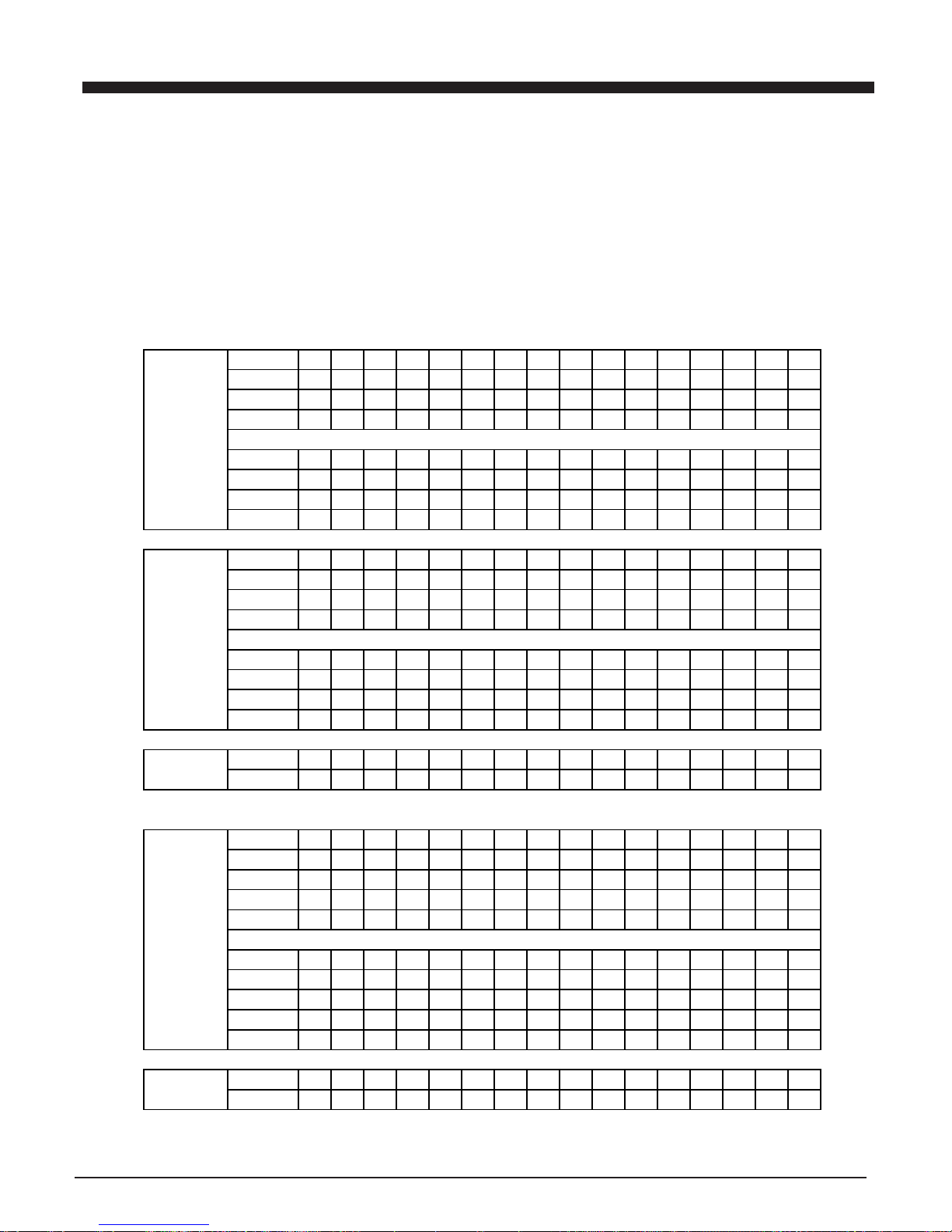
IC VOLTAGE TABLE
{DC12V,NO SIGNAL INPUT (EXCEPT FM STEREO BAND),VOLUME MINMUN}
AC 230V 50HZ LA1823 &LC72131 & TA8142P & PT2314
TUNER LA1823+LC72131 S1l9226X01 & KA9259D & S5L9279X01 & JF1M16SDT-7
PINS 12345678910111213141516
AM
1.27 1.27 4.61 4.61 2.62 0 0.02 3.38 4.5 1.29 1.28 0.35 4 0.03 0.15 0.74
FM 1.29 1.29 4.43 4.43 2.16 0 0.02 3.38 4.42 1.29 1.28 0.3 3.67 3.74 3.7 0.73
FM.ST 1.29 1.29 4.43 4.43 2.16 0 0.02 3.38 4.42 1.29 1.28 0.3 3.67 3.74 3.7 0.73
IC102
LA1823 PINS 17 18 19 20 21 22 23 24
AM
0.74 1.25 0.32 4.61 4.61 4.61 0 0
FM 0.74 1.25 1.39 4.47 4.46 4.39 0 0.91
FM.ST 0.74 1.25 1.39 4.47 4.36 4.39 0 0.91
PINS 12345678910111213141516
AM
2.25 00333.64 3.78 3.78 0 0.02 4.45 0.3 0 0 0 0.22
FM 2.19 0 0 0.2 3 3.64 3.9 0.02 0 0.02 4.45 0 0 0 0.3 2.18
IC103 FM.ST 2.2 0 0 0.2 3 3.64 3.79 3.79 0 0.02 4.45 0 0 0 0.2 2.18
LC72131
PINS 17 18 19 20 21 22
AM
4.5 0.82 0.82 3.1 0 2.3
FM 4.5 0.82 0.82 3.1 0 2.3
FM.ST 4.5 0.82 0.82 3.1 0 2.3
IC201 PINS 12345678910111213141516
TA8142P TAPE
0 1.2 2.1 1.5 7 2.1 1.2 0 0 1.2 2.3 0 0.7 2.3 1.3 0
PINS 12345678910111213141516
RADIO
6.34 0 3.18 3.18 3.19 3.2 3.19 3.18 3.18 3.18 3.18 3.19 3.18 3.18 3.18 3.18
CD 6.34 0 3.18 3.18 3.19 3.2 3.19 3.18 3.18 3.18 3.18 3.19 3.18 3.18 3.18 3.18
TAPE 6.34 0 3.18 3.18 3.19 3.2 3.19 3.18 3.18 3.18 3.18 3.19 3.18 3.18 3.18 3.18
IC401 AUX 6.34 0 3.18 3.18 3.19 3.2 3.19 3.18 3.18 3.18 3.18 3.19 3.18 3.18 3.18 3.18
PT2314
VOLUM PINS 17 18 19 20 21 22 23 24 25 26 27 28
RADIO
3.19 3.2 3.18 3.19 3.18 3.2 3.2 3.2 0 0.22 3.05 3.19
CD 3.19 3.2 3.18 3.19 3.18 3.2 3.2 3.2 0 0.22 3.05 3.19
TAPE 3.19 3.2 3.18 3.19 3.18 3.2 3.2 3.2 0 0.22 3.05 3.19
AUX 3.19 3.2 3.18 3.19 3.18 3.2 3.2 3.2 0 0.22 3.05 3.19
IC301 PINS 123456789101112131415
TA8229K POWER
0 16.8 9 17.5 9.1 17 0 17.2 9.1 0.5 0 0 0.6 0 0
VOLTAGE CHARTS
12

PINS 12345678910111213141516
DRAM 3.41 2.52 2.42 0 2.2 2.21 3.41 2.2 2.2 0 2.19 2.2 3.41 0 3.41 3.41
U7
SDRAM PINS 17 18 19 20 21 22 23 24 25 26 27 28 29 30 31 32
16M
DRAM 3.41 0 0 3.41 00003.41 00000.21 3.41 0
PINS 33 34 35 36 37 38 39 40 41 42 43 44 45 46 47 48
DRAM 0.11 1.69 3.41 0 3.41 2.44 2.45 0 2.41 2.45 3.41 2.43 2.44 0 2.43 2.45
PINS 49 50
DRAM 2.45 0
PINS 12345678910111213141516
RADIO
1.41 00000000002.88 0 1.39 1.32 0
CD 1.41 00000000002.88 0 1.39 1.32 0
TAPE 1.41 00000000002.88 0 1.39 1.32 0
AUX 1.41 00000000002.88 0 1.39 1.32 0
PINS 17 18 19 20 21 22 23 24 25 26 27 28 29 30 31 32
RADIO
1.08 1.36 2.87 0 0 0.86 0.3 0.08 0 2.92 1.39 2.92 2.92 2.92 0 1.05
CD 1 1.36 2.87 0 0 2.87 2.87 2.87 0 2.92 1.39 2.92 2.92 2.92 0 1.05
TAPE 1 1.36 2.87 0 0 2.87 0.3 0.25 0 2.92 1.39 2.92 2.92 2.92 0 1.05
U2 AUX 1 1.36 2.87 0 0 2.87 0.3 0.25 0 2.92 1.39 2.92 2.92 2.92 0 1.05
S3C825A
PINS 33 34 35 36 37 38 39 40 41 42 43 44 45 46 47 48
RADIO
0 0 002.86 1.81 2.86 00002.73 2.73 3.4 3.54 2.91
CD 0 2.88 0 0 2.86 1.81 2.86 0 0 2.79 0 0 0 0.06 0.3 2.91
TAPE 00002.86 1.81 2.86 00002.73 2.73 0.03 0.7 2.91
AUX 00002.86 1.81 2.86 00002.73 2.79 0.03 0.7 2.91
PINS 49 50 51 52 53 54 55 56 57 58 59 60 61 62 63 64
RADIO
0 0 2.88 0 2.88 1.42 1.42 1.42 1.42 1.42 1.42 1.42 1.42 1.42 1.42 1.42
CD 2.91 0 2.88 0 2.88 1.42 1.42 1.42 1.42 1.42 1.42 1.42 1.42 1.42 1.42 1.42
TAPE 2.91 0 2.88 0 2.88 1.42 1.42 1.42 1.42 1.42 1.42 1.42 1.42 1.42 1.42 1.42
AUX 2.91 0 2.88 0 2.88 1.42 1.42 1.42 1.42 1.42 1.42 1.42 1.42 1.42 1.42 1.42
PINS 65 66 67 68 69 70 71 72 73 74 75 76 77 78 79 80
RADIO
1.42 1.42 1.42 1.42 1.42 1.42 1.42 1.42 1.42 1.42 1.42 1.42 1.42 1.42 1.42 1.42
CD 1.42 1.42 1.42 1.42 1.42 1.42 1.42 1.42 1.42 1.42 1.42 1.42 1.42 1.42 1.42 1.42
TAPE 1.42 1.42 1.42 1.42 1.42 1.42 1.42 1.42 1.42 1.42 1.42 1.42 1.42 1.42 1.42 1.42
AUX 1.42 1.42 1.42 1.42 1.42 1.42 1.42 1.42 1.42 1.42 1.42 1.42 1.42 1.42 1.42 1.42
PINS 12345678910111213141516
MOTOR 3.7 3.7 1.69 1.69 7.38 4.99 4.99 0 1.69 1.69 3.7 3.72 0 0 3.72 3.72
U5
KA9259D PINS 17 18 19 20 21 22 23 24 25 26 27 28
MOTOR 3.72 3.72 1.69 4.32 8 0 1.69 1.69 1.69 3.72 3.72 0
VOLTAGE CHARTS
13

PINS 12345678910111213141516
DSP
1 2.07 0 0 0 2.07 0 0 1.7 1.69 3.38 3.38 1.69 0 0 0
PINS 17 18 19 20 21 22 23 24 25 26 27 28 29 30 31 32
DSP
3.38 1.66 000003.38 000003.38 0 0
U3
S5L9279 PINS 33 34 35 36 37 38 39 40 41 42 43 44 45 46 47 48
DSP
0 0 3.38 0 0 3.31 3.37 3.38 0 2.07 0 2.45 2.46 2.51 2.46 2.48
PINS 49 50 51 52 53 54 55 56 57 58 59 60 61 62 63 64
DSP
2.46 2.48 2.09 0 0 2.4 2.82 2.62 2.7 0.77 0.73 0.36 2.76 2.07 0 1.13
PINS 65 66 67 68 69 70 71 72 73 74 75 76 77 78 79 80
DSP
0 2.76 1.72 3.38 3.38 0 3.38 0 0 3.38 3.38 1.69 0000
PINS 81 82 83 84 85 86 87 88 89 90 91 92 93 94 95 96
DSP
0 0 1.61 1.7 2.07 0 2.88 0 2.75 1.63 0 0.06 0000
PINS 97 98 99 100
DSP
0 0.07 1.69 0
PINS 12345678910111213141516
SSP
1.71 1.75 1.69 1.52 1.7 3.38 1.7 0.82 1.69 1.68 1.72 1.63 3.38 2.79 2.82 2.87
U1
S1L9226 PINS 17 18 19 20 21 22 23 24 25 26 27 28 29 30 31 32
SSP
2.87 0.07 1.69 0 0 0 1.71 1.71 1.71 1.71 1.71 1.71 1.71 1.71 1.71 1.71
PINS 33 34 35 36 37 38 39 40 41 42 43 44 45 46 47 48
SSP
0 1.71 1.66 1.66 3.37 0 1.71 1.71 1.71 1.71 1.69 1.22 0.89 2.5 1.71 2.45
IC302 PINS 1 2 3 IC901 PINS 1 2 3
KA7808
14 0 8 RECEIVEER 4.4 0 4.4
Q308 PINS E B C Q105 PINS E B C
D882
5.45 6 12.9 9014C 10.3 11 16.8
Q307 PINS E B C Q113 PINS E B C
8050
7.6 8.2 11.9 9014C 4.5 5.2 7.6
REMARK : ALL THE DATA IN THE TABLE IS FOR.REFERENCE ONLY
FOR FM.ST BAND , FM STEREO INDICATOR MUST BE ON.
VOLTAGE CHARTS
14
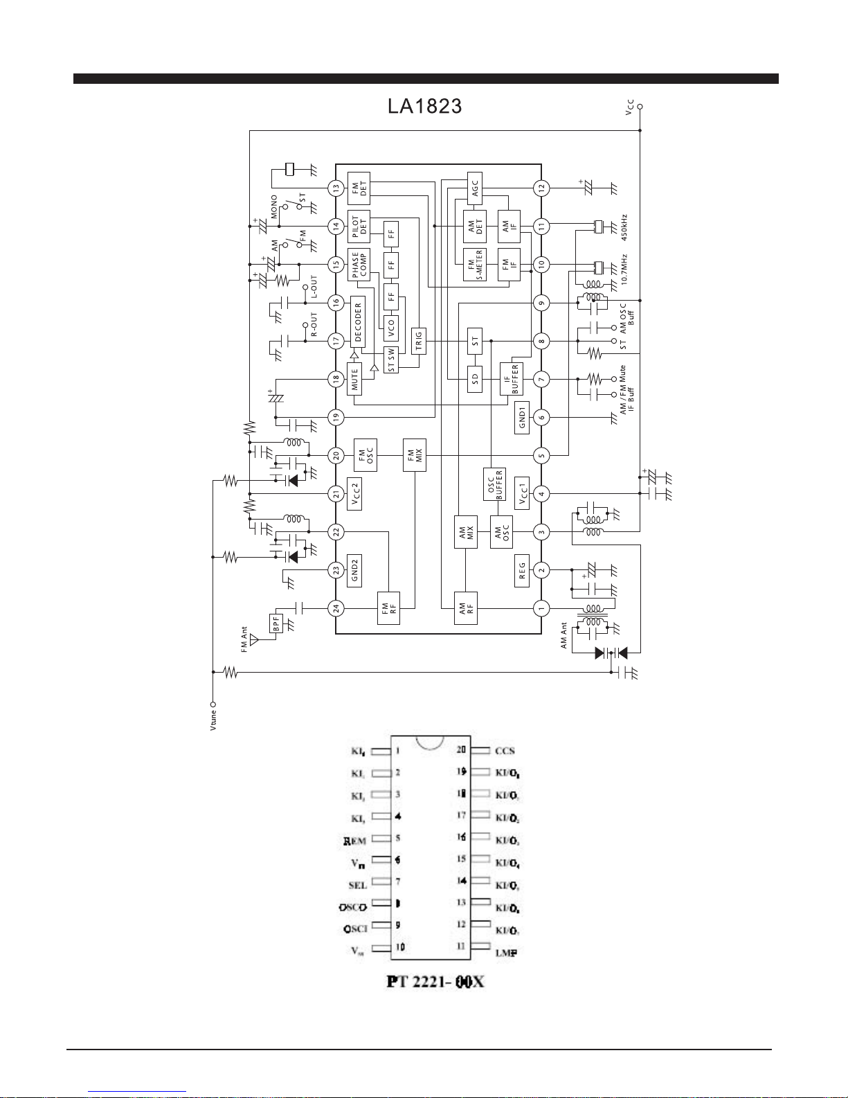
IC BLOCK DIAGRAM
15
 Loading...