

Page 1

English Italiano
DDTT AAMM GGrraaddee 3
HHiigghh CCeeiilliinngg MMoouunntt DDeetteeccttoorr
IInnssttaallllaattiioonn GGuuiiddee
MMooddeell:: RRKK220000DDTTGG33
3
Português
Françias Español
Nederlands
Page 2

Page 3

English
MMooddeell:: RRKK220000DDTTGG33
HHiigghh CCeeiilliinngg MMoouunntt DDeetteeccttoorr
IInnssttaallllaattiioonn GGuuiiddee
DDTT AAMM GGrraaddee 3
3
Page 4

General Description
The Industrial LuNAR DT AM Grade 3 (RK200DTG3) is a dual technology ceiling detector with a
mounting height of up to 8.6m (28ft) that incorporates RISCO Group’s Anti-Cloak™ Technology (ACT™).
The detector has an Intelligent Digital Signal Processing method that automatically adjusts the alarm
threshold and pulse count verification according to actual intruder crossing speed and environmental
factors, providing superior detection and false alarm immunity.
The Ind. LuNAR RK200DTG3 can operate as a regular relay detector connected to any control panel, or
as an addressable BUS detector when connected to RISCO Group’s ProSYS control panel via the RS485
BUS.
Ind. LuNAR RK200DTG3 Features
♦ PD6662, EN50131-1, EN50131-2-4 Grade 3
♦ Addressable Dual Technology detector with Anti-Cloak™ Technology
♦ Up to 8.6 m (28ft) mounting height
♦ 360
♦ 3 independent PIR channels for customized coverage
♦ Intelligent Digital Signal Processing – alarm verification and decision thresholds adjusted
♦ Built-in Triple EOL resistors, jumper selectable
♦ Active IR for Anti-Masking meeting EN50131 requirements
♦ Ceiling and cover tampers
♦ "Green Line" setting – for disabling the MW when the premises are occupied
♦ Opto–relays for low current consumption and long life
♦ Remote and Local Self Test
♦ Remote SET input
♦ Remote RC control input
♦ PIR coverage optimization by sliding the lenses
♦ Microwave Range Adjustment manually (analog trimmer) and remotely (digital setting)
♦ Trouble Indication (by LEDs or via communication)
♦ 3 Triple color LEDs for easy walk testing
♦ Advanced Remote control and diagnostics
♦ Reduced Power Consumption when connected to RISCO Group’s ProSYS
0
by 18m (60ft) diameter coverage pattern
according to actual intruder crossing speed
Ind. LuNAR RK200DTG3 Installation Guide 2
Page 5

Remote Control and Diagnostic Features*
♦ Remote microwave adjustment enables one-man walk test.
♦ Diagnostic tools include detector input voltage reading and status of each PIR channel and
MW channel (signal voltage and noise levels), AM channel (signal voltage), SW version
verification.
♦ Remote display and control of detector settings: MW adjustment, ACT on/off, LEDs on/off.
♦ Remote trouble indication (Pass/Fail) for the PIR, MW and power supply input
♦ Control of MW bypass (during MW trouble) and MW disable during Disarm ("Green Line")
when connected to ProSYS.
*Via the optional Bi-Directional Infrared Remote Control, or the ProSYS Upload/Download
Software and Keypad.
Detection Method
The Ind. LuNAR RK200DTG3 detection is based on:
♦ PIR (Passive Infra-Red) - which responds to changes in the IR radiation caused when an
intruder crosses the protected area.
♦ MW (Microwave) - which transmits signals and analyzes the frequency changes of the
reflected echo from an intruder using Doppler Effect.
ALARM is initiated only when both technologies trigger simultaneously (except for certain situations in
the ACT mode-see page 4 – “How ACT™ Works”), thus greatly reducing the possibility of false alarms.
English
Ind. LuNAR RK200DTG3 Installation Guide 3
Page 6

How ACT™ Works
Anti-Cloak™ Technology (ACT™) provides the benefits of DT (Dual Technology) while avoiding its
drawbacks. This patent pending innovation has created a new standard for detectors.
Dual Technology, a combination of PIR +MW, was an important development for the security
industry...but, it has 2 major weaknesses:
IR emission blocking cloaks employed by intruders enable avoidance of detection.
PIR sensitivity is reduced when the protected area’s ambient temperature approaches body
temperature.
Responding to requests from its customer base to solve these pressing problems, RISCO Group
developed ACT™ -a revolutionary anti-cloak solution.
ACT™ prevents the alarm system from being bypassed, by neutralizing attempts to camouflage IR
radiation. Using unique pattern recognition algorithms, ACT™ distinguishes between the weak IR
signal of a moving intruder and the background noise and thermal interferences that may cause
false alarms.
Once the presence of an intruder is recognized, ACT™ switches the system automatically from dual
channel PIR/MW mode to single channel MW mode for a predetermined period of time, in order to
trigger an alarm utilizing the MW channel, and then returns to dual channel mode.
In the second case, when the ambient temperature approaches body temperature, the ACT™
switches to microwave-only detection.
Offering significantly higher detection capabilities as well as immunity from false alarms, ACT™
thwarts even the most sophisticated burglars.
Ind. LuNAR RK200DTG3 Installation Guide 4
Page 7
Ind. LuNAR RK200DTG3 Configuration Options
The Ind. LuNAR RK200DTG3 can be configured and/or diagnosed remotely via one of the options:
ACT Mode
LEDs
MW Sensitivity
Diagnostics
Status/Trouble/Info Reports
AM Diagnostics
MW Bypass
MW Disable on Disarm
("Green Line")
Manual
configuration
(by trimmer)
-
-
- -
- -
- -
Remote
Control
Device
ProSYS Bus
Control
LED Display
The three Tri color LEDs in the Ind. LuNAR RK200DTG3, operate as herein described:
LED STATE MEANING
Steady
Red
Green
Orange
All LEDs
Flashing with low frequency
Flashing with high frequency AM detection
Steady Microwave detection
Flashing Trouble in the MW channel
Steady PIR detection
Flashing Trouble in the PIR channel
Flashing with change of color Upon power up
Detector alarm (simultaneous PIR and MW
detection)
Indicates malfunctioned communication
with ProSYS
English
Ind. LuNAR RK200DTG3 Installation Guide 5
Page 8

INSTALLATION
Preliminary steps:
♦ Before installation, study the space to be protected carefully in order to choose the exact
location of the unit for the best possible coverage.
♦ Never install the Ind. LuNAR RK200DTG3 in an environment that causes an alarm condition
in one technology.
♦ Avoid installations where rotating machines (e.g. fans) are normally in operation within the
coverage pattern. Point the unit away from glass exposed to the outdoors and objects that
may change temperature rapidly.
♦ Do not mount the detector in direct sunlight or near any heat sources. Detection sectors
should be pointed either towards a wall, floor but not towards windows or curtains. The
installation surface should be solid, smooth and vibration free
♦ Eliminate interference from nearby outside sources.
♦ For optimum detection, select a location likely to intercept an intruder moving across the
coverage pattern.
♦ Recommended mounting heights that allow 18m (60ft) detection, are from 3.7m to 8.6m.
♦ The detector must be mounted on the ceiling, preferably in the center of the room.
Ind. LuNAR RK200DTG3 Installation Guide 6
Page 9
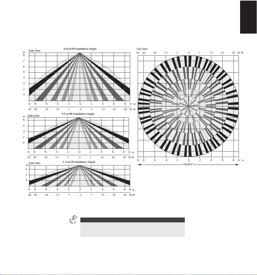
Typical Ind. LuNAR RK200DTG3 detection coverage and installation height, are illustrated below:
English
NOTE:
When installing the Ind. LuNAR RK200DTG3 detector
in a room occupied with high volume interfering
Ind. LuNAR RK200DTG3 Installation Guide 7
elements, MW detection may be affected.
Page 10
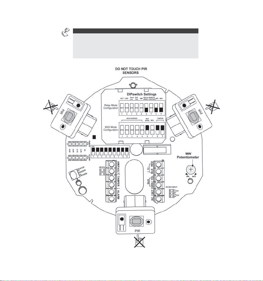
Installation Process:
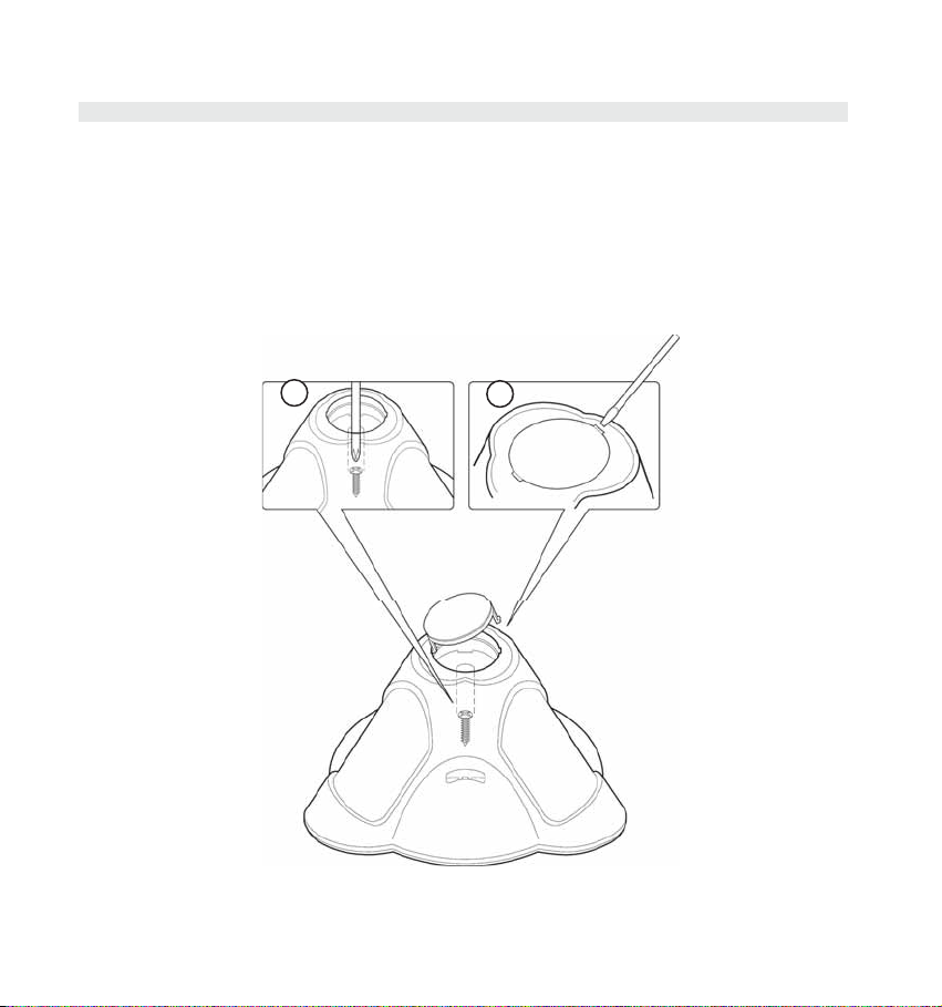
To open the detector (Figure 1), remove the cover by inserting a screwdriver (1) in the recess
between the detector’s protection cap and the cover. The cover will remain attached to the base of
the detector.
Using a Philips screwdriver, release the upper cover screw (2) and gently pull upward the detector’s
upper cover.
2
FIGURE 1
1
Ind. LuNAR RK200DTG3 Installation Guide 8
Page 11
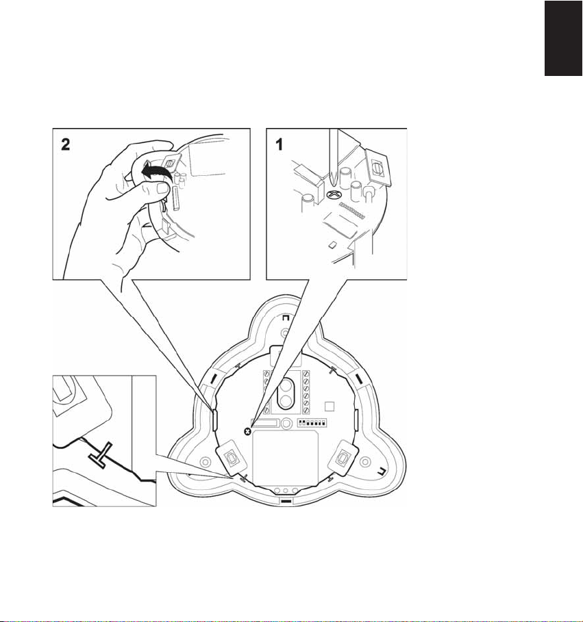
Release the PCB holding screw (Figure 2) located on the right hand side of the PCB (1), pull gently
the two release clips (2) outward and remove the PCB.
Do not touch
the PIR
sensors!
FIGURE 2
Do not remove
the white filters
from their
position! They are
essential for
correct operation
of the detector.
English
Ind. LuNAR RK200DTG3 Installation Guide 9
Page 12
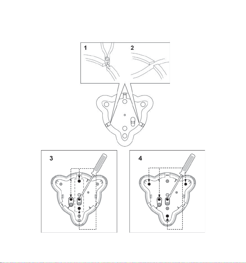
If required, open (Figure 3) the wiring channels knockout using a cutter (1, 2) and knockout holes in
the rear cover (3, 4) using a screwdriver.
FIGURE 3
Ind. LuNAR RK200DTG3 Installation Guide 10
Page 13
Insert the cable via the cable opening (Figure 4) and connect the desired wires as described in
“Step 4- Wiring”.
English
FIGURE 4
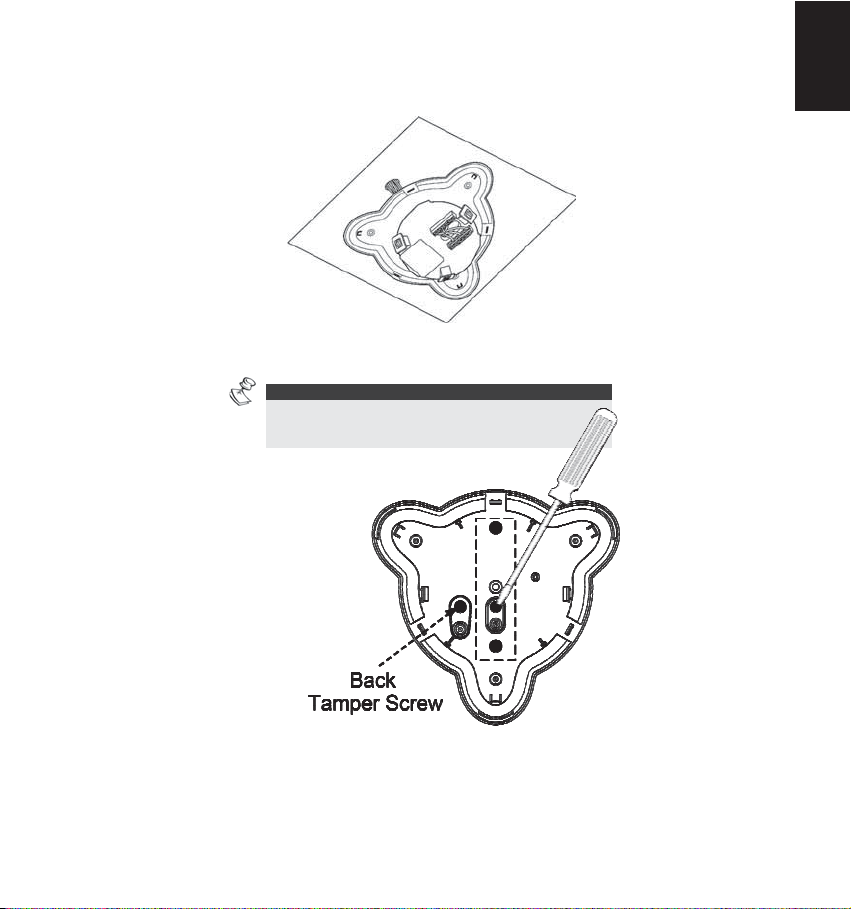
Mount the rear cover in its final location (Figure 5) using the 3 mounting screws and seal the
remaining open holes with sealant.
NOTE:
When a single gang box is used, use 2 additional
screws to mount the base to the single gang box.
The back tamper cannot be used in this case!
FIGURE 5
FIGURE -5
Return the PCB to its previous location and verify that it is well secured by the holding clips and the
screw.
Ind. LuNAR RK200DTG3 Installation Guide 11
Page 14
Perform lens adjustment and DIP switch settings as described in “Lens Adjustment” on page 12
and on page 15.
Mount the top cover on the detector’s base.
Tighten the top cover’s central screw.
Replace the detector’s protection cap.
NOTE:
For a ceiling tamper, affix the back tamper screw as
shown in Figure 5.
Lens Adjustment:
The Ind. LuNAR RK200DTG3 has three - Fresnel lenses attached to the cover, located in sensor
protective sleeves. Adjust the position of the lenses based on the ceiling mounting height as follows:
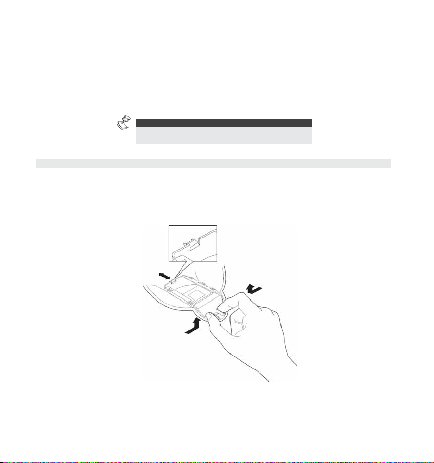
Press the 2 clips attaching the sleeve (Figure 6) to the detector’s cover, and gently pull out the
sleeve.
FIGURE 6
Ind. LuNAR RK200DTG3 Installation Guide 12
Page 15
Remove the lens from the sleeve (Figure 7) by gently lifting it from the holding pins that secure it to
the sides of the sleeve.
English
FIGURE 7
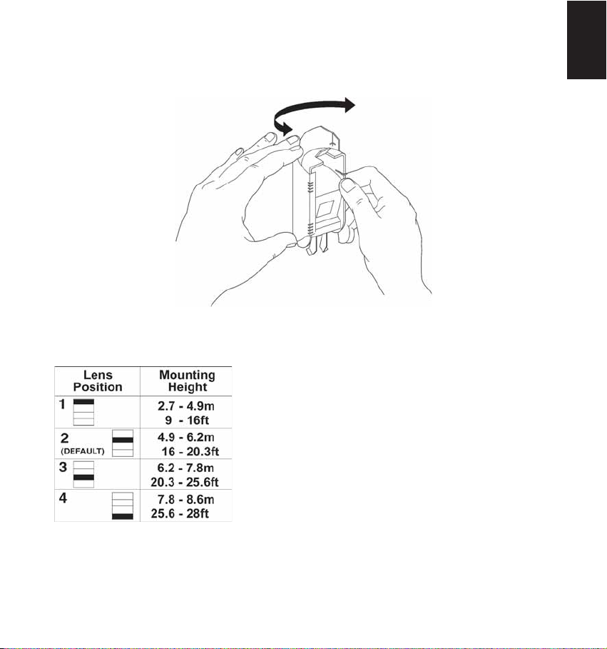
Place the two pins, which are located on both sides of the sleeve into the matching slots on the lens.
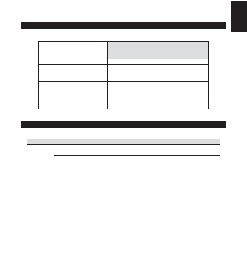
Use the following table to select the desired lens position.
Return the protective sleeve back into place on the detector front cover.
Repeat steps 1 to 5 for the remaining 2 lenses.
Ind. LuNAR RK200DTG3 Installation Guide 13
Page 16
NOTES:
Below 3.7m mounting height, the coverage diameter starts
decreasing, and at 2.7m height coverage diameter is 15m (50ft).
For customized coverage, it is possible to set the position of
each lens to a different height, according to the installation
conditions.
Ind. LuNAR RK200DTG3 Installation Guide 14
Page 17
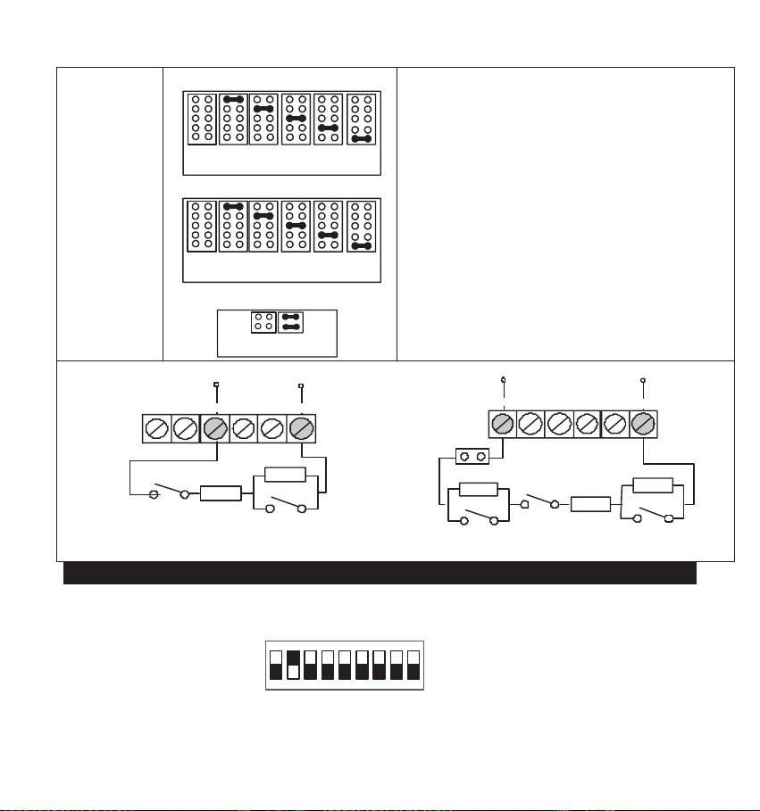
Selectors and Jumpers
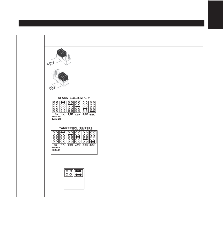
RC/SET
INPUT
EOL
RESISTORS
JUMPERS
Used to determine the polarity of the external inputs.
12V: 12v has to be connected in order activate the function.
GND or N.C. has no influence on the RC/SET status.
(see Relay mode DIP switches configuration)
0V: The GND has to be connected in order to activate the
function.
12v or N.C. has no influence on the RC/SET status.
(see Relay mode DIP switches configuration)
FAULT/AM EOL
JUMPERS
The jumpers are used when connecting the
detector to a DEOL or TEOL Zone. The jumpers
allow the selection of TAMPER, ALARM E.O.L
resistors (1K, 2.2K, 4.7K, 5.6K or 6.8K), according
to the control panel settings. An additional double
jumper allows the connection of 12K FAULT/AM
E.O.L resistor (see EOL Resistors Schematic).
Follow the terminal block connection diagram
when connecting the detector to a Double/Triple
End Of Line (DEOL/TEOL) Zone
English
12K
No
Resistor
(Default)
Ind. LuNAR RK200DTG3 Installation Guide 15
Page 18
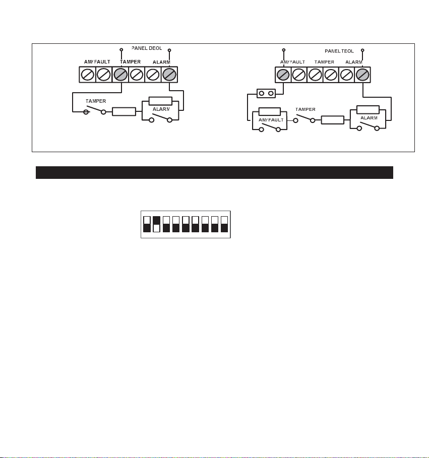
Schematic of EOL Resistors
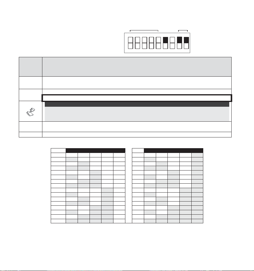
DIP Switch Settings
The Ind. LuNAR RK200DTG3 has a 9 position DIP switch that changes functionality for use in
Relay mode or in BUS operation mode. Set the DIP switch according to the tables below:
Factory Default Settings:
ON
123456789
Ind. LuNAR RK200DTG3 Installation Guide 16
Page 19
Relay Mode Configuration (DIP
switch 6=OFF)
:
ON
ACT LED
Green
Line
Self
RELAY
REMOTE
AM
Test
MODE
CONTROL
N/AN/A
English
DIP switch
Description
2
1
34567
9
8
Number
1
Used to determine the operation of the ACT
DIP switch ON: ACT is enabled
DIP switch OFF: ACT is disabled (default factory)
2
Used to determine the operation of the detector’s LEDs
Dip switch ON: LEDs are enabled (default factory)
DIP switch OFF: LEDs are disabled
3
Used to determine the operation of the "Green Line" (See Note below)
DIP switch ON: "Green Line" is enabled
DIP switch OFF: "Green Line" is disabled (default factory)
4
Used to determine the type of Self Test (See Note below)
DIP switch ON: Local Self Test:
In case the local self test fails, the FAULT/AM Relay is activated for a period of 2.5 secs.
DIP switch OFF: Remote Self Test (default factory):
In case the remote self test passes, the Alarm Relays are activated for a period of 5 secs.
In case the test fails, FAULT/AM Relay is activated for a period of 2.5 seconds.
5
Used to determine whether Active IR Anti-Masking is active. (See Note below)
DIP switch ON: Enable
DIP switch OFF: Disable (default factory)
IMPORTANT:
If the AM is enabled via DIP Switch 5, the cover must be fitted within 1 minute from applying the
power. If the detector is already powered up and DIP Switch 5 is turned on, the unit must be
down powered to reset the AM calibration.
6
Used to determine the detector’s connection mode
DIP switch OFF: Relay mode
Used to determine if the Remote Control communication is enabled or disabled.
DIP switch ON: RC communication is always enabled.
DIP switch OFF: RC communication depends on the voltage applied to the terminal block
(default factory)
7
“RC”
When an activation signal is applied to the RC input of the terminal block, RC is enabled.
IMPORTANT:
Turn dipswitch 7 “OFF” after installation and when leaving the site for security reasons. This
will prevent unauthorized use of a remote control unit that may be used to disable the detector.
8-9 DIP switches OFF
NOTE:
See Set Terminal Blocks for activation details.
Ind. LuNAR RK200DTG3 Installation Guide 17
Page 20
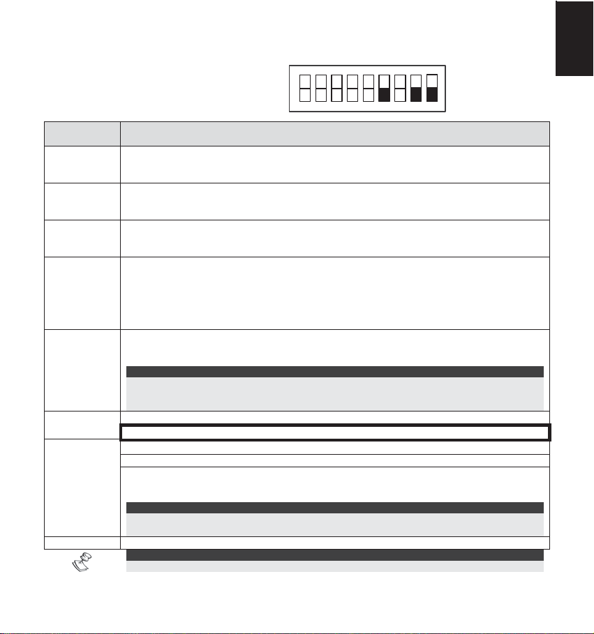
BUS Mode Configuration (DIP
switch 6=ON):
DIP
Description
BUS ADDRESS
ON
1234
5
switch
Number
1-5
Used to set the detector ID number. (See Table 1)
Set the ID number in the same way as for any other ProSYS accessory.
Used to determine the detector’s connection mode.
6
DIP switch ON: ProSYS connection – BUS configuration
NOTE:
Upon power up or normal operation, the Ind. LuNAR RK200DTG3 waits 10 seconds for ProSYS
communication. Communication problem may occur due to bad wiring, wrong address, or ProSYS
not configured properly; RED LEDs will continuously flash until the problem is solved.
Not applicable (RC
7
8-9 DIP Switch ON: in order to enable the detector to report the tamper status to ProSYS.
the ProSYS and disabled otherwise).
ID 1 2 3 4 5 ID 1 2 3 4 5
01
02
03
04
05
06
07
08
09
10
11
12
13
14
15
16
communication is automatically enabled when entering Walk Test mode in
Table 1: ID Settings for BUS connection
OFF OFF OFF OFF OFF
ON OFF OFF OFF OFF
OFF ON OFF OFF OFF
ON ON OFF OFF OFF
OFF OFF ON OFF OFF
ON OFF ON OFF OFF
OFF ON ON OFF OFF
ON ON ON OFF OFF
OFF OFF OFF ON OFF
ON OFF OFF ON OFF
OFF ON OFF ON OFF
ON ON OFF ON OFF
OFF OFF ON ON OFF
ON OFF ON ON OFF
OFF ON ON ON OFF
ON ON ON ON OFF
OFF OFF O FF OFF ON
17
ON OFF OFF OFF ON
18
OFF ON OFF OFF ON
19
ON ON OFF OFF ON
20
OFF OFF ON OFF ON
21
ON OFF ON OFF ON
22
OFF ON ON OFF ON
23
ON ON ON OFF ON
24
OFF OFF OFF ON ON
25
ON OFF OFF ON ON
26
OFF ON OFF ON ON
27
ON ON OFF ON ON
28
OFF OFF ON ON ON
29
ON OFF ON ON ON
30
OFF ON ON ON ON
31
ON ON ON ON ON
32
MODE
TAMPER
BUS
N/A
9
8
6
7
Ind. LuNAR RK200DTG3 Installation Guide 18
Page 21
Terminal Blocks
TERMINAL BLOCK 1 DESCRIPTION
+12V (RED)
- (BLK)
BUS (GRN) Used for data communication with the ProSYS
BUS (YEL)
SET ∗
RC ∗
(REMOTE
CONTROL)
WARNING:
Turn DIP switch 7 “OFF” after installation and when leaving the site for security
reasons. This will prevent unauthorized use of a remote control unit that may be used
to disable the detector.
∗
Not relevant in BUS mode
TERMINAL BLOCK 2 DESCRIPTION
AM/FAULT
TAMPER
ALARM
Power supply positive (+) input voltage
Common to control panel power supply
Used for data communication with the ProSYS
Used to remotely SET/UNSET the detector.
When an activation signal (see RC/SET Activation jumper for settings) is applied to the
SET input of the terminal block:
AM will be disabled (if the AM DIP switch 5 was previously ON)
MW module is enabled (if the Green Line DIP switch 3 was previously ON).
Removing an activation signal will cause a Self Test (if the Remote Self Test DIP switch
4 was previously OFF).
Used to enable/disable the remote control communication, only when DIP switch 7 is
“OFF”.
When an activation signal (see RC/SET input jumper for settings) is applied to the RC
input of the terminal block, Remote Control will be enabled.
DIP switch 7 “ON” constantly enables RC communication.
Note:
Normally closed output
The AM/FAULT output opens in the following events:
Detector is masked (ALARM also opens in this case)
Self Test failed
Input voltage is low (6VDC-8VDC)
Normally closed output
Normally closed output
English
Ind. LuNAR RK200DTG3 Installation Guide 19
Page 22

Walk Test
NOTE:
To perform the walk test, first enable the LEDs.
Two minutes after applying power (warm-up period), walk test the detector over the entire protected
area to verify proper operation of the detector and observe the Tri - color LED. The edge of the
microwave pattern is determined by the first red LED activation (both PIR and MW LEDs are
triggered).
NOTE:
If the PIR/MW LEDs do not TURN ON, probably it means that
there is a problem with either the lens (PIR) position, or MW
adjustment!
Adjust the microwave sensitivity by turning the PCB potentiometer (using a screwdriver), or by using
the Remote Control device. Walk test the unit from all directions to determine all the detection
pattern boundaries.
NOTE:
Adjust the MW to the lowest possible setting that will still
provide enough coverage for the entire protected area!
When using the Remote Control device, it is recommended to perform the LuNAR Self Test; for
further instructions refer to the Remote Control Instructions.
Upon completion of installation and testing stages, ensure that all switches are in their desired
positions.
IMPORTANT:
Turn DIP switch 7 “OFF” after installation and when
leaving the site for security reasons. This will prevent
unauthorized use of a remote control unit, that may be
used to disable the detector.
Ind. LuNAR RK200DTG3 Installation Guide 20
Page 23
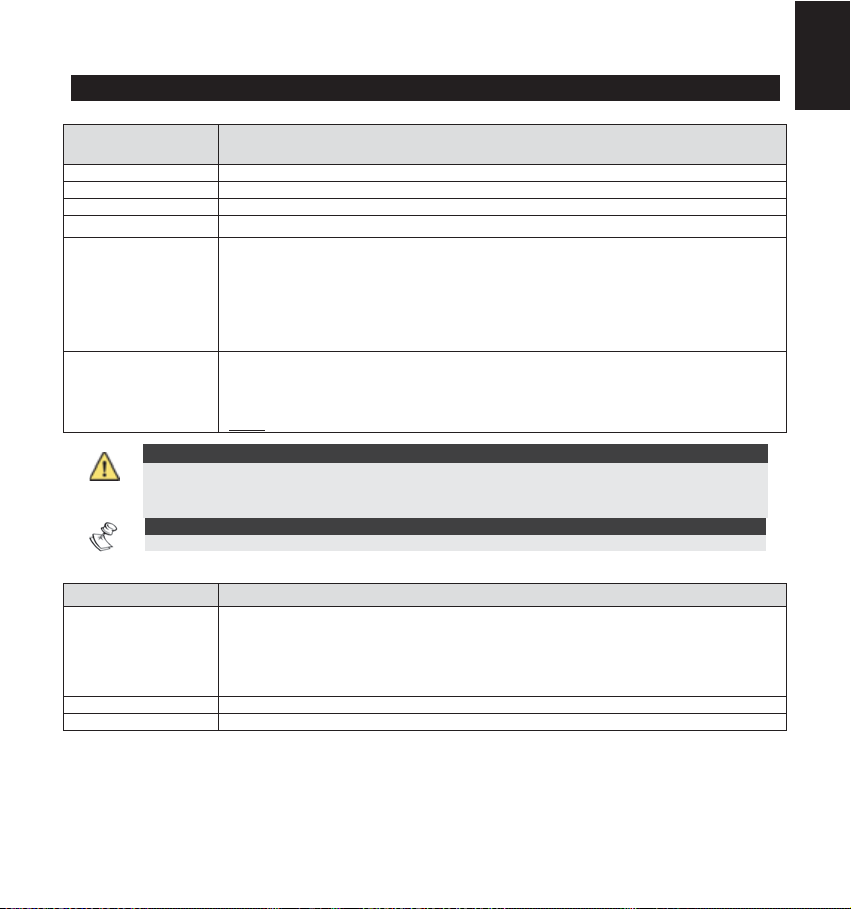
Troubleshooting
y
g
This section describes possible system problems and their solutions:
Always perform the following preliminary checks before referring to the troubleshooting table:
Perform a complete visual inspection of the Ind. LuNAR RK200DTG3, for signs of mechanical
damage, loose connections or torn wires.
Check the connections of the incoming AC power source.
Trouble Meaning Response
ProSYS Configuration of
detectors fails/not accepted by
stem
the s
Tamper indication while working
in the BUS mode
Tamper indication in the Relay
or BUS mode
Walk test cannot be initiated via
the ProSYS keypad
Green LED doesn’t operate
during Walk test - MW channel
does not function
ID configuration
problem
Tamper
connection
malfunction
Tamper probably
not closed
Wrong code Insert the appropriate code
Ind. LuNAR
RK200DTG3 is
configured (via
the ProSYS) to
the “MW disable
on DISARM”
during ProSYS’s
DISARM mode
Ind. LuNAR
RK200DTG3
operating in
Bypass mode
due to “Bypass
MW channel
mode”
Disconnect all power sources,
configure the desired IDs and
reconnect power again
Verify that both DIP 8 and 9 are in
ON position
Visually verify that ceiling tamper
and sprin
Normal behavior
Reset the detector.
If MW channel trouble reoccurs,
replace the detector with a new one
are correctly installed
English
Ind. LuNAR RK200DTG3 Installation Guide 21
Page 24

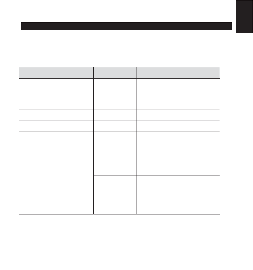
Specifications
Coverage
Variable Mounting Height From 2.7m to 8.6m (9’ to 28’), 4 lens positions according to
RFI immunity
Operating voltage
Current consumption 20mA at 12VDC, 30mA at 16 VDC, Maximum 40mA with all
Alarm and AM contacts
Tamper contacts
Alarm Time
Warm-up time
Optical Filtering for white
light
protection
Operating temperature
Storage temperature
Dimensions (Height x
Diameter)
Coverage pattern consists of 192 fingers (96 Fresnel facets)
divided into 3 lens sections.
Each lens section has 4 adjustable vertical positions for variable
mounting height and customized coverage.
360° by 18m (60ft) diameter. When mounting the detector under
3.7m, the coverage diameter starts to decrease up to 15m (50ft).
installation height
According to EN50130-4
9 to 16VDC
LEDs on.
Opto-relay NC, 100mA, 24 VDC
NC, 500mA, 24 VDC
2.2 seconds
2 minutes
Pigmented Fresnel lens
-20° C to 55° C (-4° F to 131° F)
-20° C to 60° C (-4° F to 140° F)
99mm x 194mm (3.9’’x 7.6’’)
The Ind. LuNAR RK200DTG3 detector is suitable for use in
installations complying with PD6662, EN50131-1 and EN501312-4 Grade 3, Class II.
Ind. LuNAR RK200DTG3 Installation Guide 22
Page 25

DDTT AAMM GGrraaddee 33
MMooddeelllloo:: RRKK220000DDTTGG33
RRiivveellaattoorree ddaa SSooffffiittttoo
MMaannuuaallee ddii IInnssttaallllaazziioon
nee
Italiano
Page 26

Descrizione Generale
Il LuNAR industriale DT AM Grado 3 (RK200DTG3) è un rivelatore doppia tecnologia da soffitto che può
essere installato fino ad una altezza di 8.6 metri e integra la rivoluzionaria tecnologia Anti-Cloak™
Technology (ACT™) di RISCO. Il rivelatore ha un’intelligente elaborazione digitale del segnale che
configura automaticamente le soglie di allarme e il conteggio degli impulsi in funzione del movimento
dell’intruso all’interno dell’area protetta rispetto ai fattori ambientali, garantendo la migliore rivelazione
possibile.
Il Ind. LuNAR RK200DTG3 può funzionare sia come unità “stand alone”, collegabile a qualsiasi centrale d’allarme,
sia come Accessorio BUS, collegabile via BUS RS-485 ai sistemi d’allarme RISCO serie ProSYS.
Caratteristiche del Ind. LuNAR RK200DTG3
♦ Conforme alle normative europee PD6662, EN50131-1, EN50131-2-4 Grado 3
♦ Rivelatore doppia tecnologia indirizzato con tecnologia Anti-Cloak™
♦ Installazione fino a 8.6 metri di altezza
♦ Copertura di 360
♦ 3 rivelatori PIR indipendenti per una copertura programmabile
♦ Elaborazione Digitale del Segnale – verifica dell’allarme e modifica delle soglie di
allarme in funzione del movimento dell’intruso all’interno dell’area protetta
♦ Resistenze di fine linea selezionabili tramite ponticelli
♦ IR attivo Anti-Mask conforme alle specifiche tecniche europee EN50131
♦ Interruttori antimanomissione contro l’apertura e la rimozione
♦ Configurazione "Green Line" per disabilitare le emissioni della sezione microonda
ad impianto disinserito
♦ Relè opto isolati a basso assorbimento di corrente e lunga durata
♦ Auto-test locale o remoto tramite comando remoto
♦ Ingresso di stato impianto inserito/disinserito (SET)
♦ Ingresso per l’abilitazione del dispositivo di controllo remoto (RC)
♦ Ottimizzazione della copertura PIR tramite lo spostamento delle Lenti
♦ Portata Microonda regolabile manualmente tramite potenziometro (regolazione
analogica) e in remoto (regolazione digitale)
♦ Indicazione di anomalia (tramite LED o in remoto)
♦ 3 LED con tricolore per effettuare agevolmente la prova di copertura
♦ Controllo e diagnostica remota avanzata
♦ Limitazione dell’assorbimento in corrente se collegato ai sistemi d’allarme ProSYS
0
con 18 metri di diametro
Ind. LuNAR RK200DTG3 - Guida all’installazione 2
Page 27

Caratteristiche di Controllo e Diagnostica Remota*
♦ Regolazione remota della microonda.
♦ Le utilità di diagnostica includono la lettura della tensione di alimentazione del
rivelatore, lo stato dei 3 canali PIR (Infrarosso) e del canale MW (microonda)
(tensione del segnale e livelli di rumore) e la verifica della versione del
firmware.
♦ Visualizzazione remota e controllo della configurazione dell’unità per quanto
riguarda la regolazione della microonda, l’ACT (on/off) e i LED (on/off).
♦ Indicazione remota di anomalia per la sezione PIR, MW e l’ingresso di
alimentazione.
♦ Controllo ed esclusione microonda MW (in caso di anomalia MW) e
disabilitazione microonda MW durante il periodo in cui l’impianto d’allarme è
disinserito (funzione “Green Line”), se collegato via bus ai sistemi d’allarme
ProSYS.
*Tramite il dispositivo bidirezionale di controllo all’infrarosso (opzionale) o il software di
teleassistenza se l’unità è collegata via BUS ad un sistema d’allarme ProSYS.
Sistema di Rilevazione
La rilevazione del Ind. LuNAR RK200DTG3 si basa sulle seguenti tecnologie:
♦ PIR (Infrarosso Passivo) – rileva il cambiamento di temperatura che viene
generato da un intruso che attraversa l’area protetta dal sensore.
♦ MW (Microonda) – trasmette segnali e analizza la variazione di frequenza
degli stessi causata da un intruso che si muove all’interno dell’area protetta.
Questa tecnologia lavora con il principio dell’effetto Doppler.
L’ALLARME viene generato solo quando entrambe le tecnologie di rilevazione vengono attivate
simultaneamente (ad eccezione del funzionamento con ACT – consultare la pagina 4 – “Come
funziona l’ACT™”), riducendo drasticamente la percentuale di allarmi impropri.
Italiano
Ind. LuNAR RK200DTG3 - Guida all’installazione 3
Page 28

Come funziona l’ACT™
Anti-Cloak™ (ACT™) è la prima vera innovazione della tecnologia di rivelazione volumetrica
antintrusione dall'introduzione della tecnologia ad Infrarosso Passivo. Offrendo i benefici di un
rivelatore a Doppia Tecnologia ma allo stesso tempo sopperendo ai suoi punti deboli, questa
innovazione, in attesa di brevetto, costituisce un nuovo standard nella tecnologia dei rivelatori
antintrusione.
I rivelatori a doppia tecnologia Microonda e Infrarosso Passivo sono stati un importante sviluppo per
l'industria della sicurezza per la loro capacità di riduzione degli allarmi impropri. Essi però hanno due
grandi punti deboli:
Gli intrusi possono evitare di essere rilevati dal canale IR bloccando le radiazioni infrarosse del
proprio corpo con un grosso ombrello, un cartone o altro.
La sensibilità del PIR si riduce notevolmente quando vengono protette aree in cui la temperatura
ambientale raggiunge quella del corpo umano.
In risposta alle richieste dei clienti di risolvere queste problematiche, RISCO ha sviluppato la
rivoluzionaria tecnologia chiamata ACT™.
ACT™ previene la neutralizzazione del sistema di allarme quando il canale all'infrarosso dei normali
rivelatori a doppia tecnologia viene messo in condizione di non rilevare un intruso. Utilizzando
algoritmi che analizzano la forma d'onda e la frequenza dei segnali infrarossi, ACT™ identifica il
segnale particolarmente basso di un intruso in movimento rispetto ad interferenze termiche che
potrebbero essere causa di allarmi impropri.
Una volta che la presenza di un intruso è stata rilevata, ACT™ commuta automaticamente il
rivelatore da doppia tecnologia al funzionamento in solo Microonda per un periodo di tempo
determinato al fine di attivare l'allarme con il solo canale Microonda.
Nel secondo caso, quando la temperatura dell'ambiente protetto si avvicina alla temperatura del
corpo umano, ACT™ commuta in microonda singola.
ACT™ garantisce rilevazione dell’intruso anche in condizioni critiche ed elevata immunità ai falsi
allarmi.
Ind. LuNAR RK200DTG3 - Guida all’installazione 4
Page 29
Opzioni di Configurazione del Ind. LuNAR RK200DTG3
Il Ind. LuNAR RK200DTG3 può essere configurato e/o testato in remoto tramite le opzioni elencate
nella tabella che segue:
Modo ACT
Abilitazione LED
Sensibilità MW
Diagnostica
Stato/Anomalie/Informazioni
Diagnostica AM
Esclusione MW se in
anomalia
Disabilita MW in disinserito
(Funzione "Green Line")
Locale sul
rivelatore
(via trimmer)
-
-
- -
- -
- -
Dispositivo
Remoto
Da centrale
ProSYS
Indicatori LED
I tre LED tricolori del Ind. LuNAR RK200DTG3, riportano le informazioni che seguono:
LED STATO SIGNIFICATO
Acceso
Rosso
Verde
Arancio
Tutti i LED
Lampeggiante lento
Lampeggiante veloce Rilevazione circuito Anti-Mask (AM)
Acceso Rilevazione canale Microonda (MW)
Lampeggiante Anomalia canale Microonda (MW)
Acceso
Lampeggiante Anomalia canale Infrarosso (PIR)
Lampeggianti con cambio di colore Alimentazione iniziale
Rivelatore in allarme (rilevazione
simultanea su canale PIR e MW)
Anomalia di comunicazione con la centrale
ProSYS
Rilevazione canale Infrarosso (PIR)
Ind. LuNAR RK200DTG3 - Guida all’installazione 5
Italiano
Italiano
Page 30

INSTALLAZIONE
Fase preliminare:
♦ Prima di procedure con l’installazione, studiare attentamente l’area da
proteggere al fine di trovare la corretta locazione del rivelatore per la migliore
copertura possibile.
♦ Non installare mai il LuNAR in un ambiente con un disturbo che causa una
condizione d’allarme persistente in una delle due tecnologie.
♦ Evitare installazioni in presenza oggetti in movimento (ad esempio ventole)
che operano normalmente nell’area coperta dal rivelatore. Puntare l’unità
lontano da vetrate che danno all’esterno o oggetti che possono cambiare
temperature rapidamente.
♦ Non installare il rivelatore in posizioni che possano essere colpite da raggi
solari diretti o vicino a sorgenti di calore. Le zone di rilevazione dovrebbero
essere posizionate davanti a pareti, pavimenti ma non di fronte a tendaggi. La
superficie di installazione deve essere solida, liscia ed esente da vibrazioni.
♦ Per un’ottima rilevazione scegliere la posizione di installazione in modo che
l’eventuale intruso si introduca nell’area protetta attraversando le zone sensibili
del rivelatore.
♦ L’altezza di installazione consigliata, per una copertura con un diametro di 18
metri, và da 3.7 a 8.6 metri. Installato a 2.7 metri di altezza il rivelatore ha una
copertura caratterizzata da un diametro di 15 metri.
♦ Il rivelatore và montato a soffitto, preferibilmente al centro dell’area da
proteggere.
Ind. LuNAR RK200DTG3 - Guida all’installazione 6
Page 31

I diagrammi di copertura tipici e le relative altezze di installazione sono di seguito illustrate:
Italiano
NOTE:
Quando il rivelatore Ind. LuNAR RK200DTG3 viene
installato in un ambiente ove sono presenti elementi
che causano interferenze, la MW potrebbe avere una
Ind. LuNAR RK200DTG3 - Guida all’installazione 7
copertura ridotta o un funzionamento anomalo.
Page 32

Procedura di installazione:
1. Per aprire il rivelatore (Figura 1), inserire un cacciavite nella fessura tra il tappo di protezione
superiore e il coperchio. Il coperchio rimarrà agganciato alla base del sensore.
2. Con il cacciavite svitare la vite del coperchio e tirare a sé il coperchio.
2
FIGURA 1
1
Ind. LuNAR RK200DTG3 - Guida all’installazione 8
Page 33

3. Allentare la vite di fissaggio della scheda elettronica (Figura 2) posizionata sul lato destro della
scheda (1), premere verso l’esterno le 2 clip di sblocco (2) e rimuovere la scheda elettronica.
Non toccare
con le dita
l’elemento
FIGURA 2
piroelettrico !
Italiano
Ind. LuNAR RK200DTG3 - Guida all’installazione 9
Non rimuovere i filtri bianchi di protezione
dei PIR dalla loro posizione. Essi sono
indispensabili per il corretto funzionamento
del sensore.
Page 34

4. Se necessario, aprire con una tronchesina (Figura 3) le predisposizioni per il passaggio cavi
(1, 2) e con un cacciavite i fori a sfondare situati nella base del contenitore (3, 4).
FIGURA 3
Ind. LuNAR RK200DTG3 - Guida all’installazione 10
Page 35

5. Inserire il cavo facendolo passare (Figura 4) tramite gli appositi passaggi ed effettuare i
collegamenti descritti nel paragrafo “Fase 4- Cablaggio”.
FIGURA 4
6. Installare la base del contenitore (Figura 5) nella posizione finale usando 3 viti di fissaggio e
sigillare i restanti fori aperti con del sigillante.
NOTA:
Se si utilizza una scatola elettrica per montare il
rivelatore, usare 2 viti aggiuntive per fissare la
base del rivelatore alla scatola.
In questo caso verificare che sia possibile
utilizzare il tamper antirimozione!
FIGURA 5
7. Inserire la scheda elettronica nella posizione originale e verificare che sia bloccata dalle clip e
dalla vite di fissaggio.
Italiano
Ind. LuNAR RK200DTG3 - Guida all’installazione 11
Page 36

8. Effettuare la regolazione delle lenti e la predisposizione dei microinterruttori come descritto nel
paragrafo “Regolazione delle Lenti” alla pagina 12 e “Configurazione Microinterruttori” alla
pagina 15.
9. Montare il coperchi del rivelatore sulla base.
10. Stringere il coperchio tramite l’apposita vite centrale.
11. Riposizionare il tappo di protezione del rivelatore.
NOTA:
Per montare il tamper antirimozione a soffitto,
posizionare la vite del tamper come mostrato in Figura
5.
Regolazione delle Lenti:
Il Lunar ha tre lenti di Fresnel pigmentate integrate nel coperchio del rivelatore inserite all’interno di
una sezione plastica che protegge gli elementi piroelettrici. Regolare la posizione di queste tre lenti
in funzione dell’altezza di installazione come di seguito spiegato:
1. Premere le 2 clip di sblocco del supporto plastico (Figura 6) che mantiene la lente tirandolo
verso l’esterno.
FIGURA 6
2. Rimuovere la lente sganciandola dai supporti laterali (Figura 7) che la fissano alla sua
custodia plastica.
Ind. LuNAR RK200DTG3 - Guida all’installazione 12
Page 37

FIGURA 7
Italiano
3. Posizionare i 2 supporti laterali posizionati ai lati della custodia plastica negli appositi fori della
scala verticale della lente facendo riferimento alla tabella seguente.
4. Riposizionare la custodia plastica della lente nel coperchio del Lunar.
5. Effettuare la stessa procedura per le altre 2 lenti.
Ind. LuNAR RK200DTG3 - Guida all’installazione 13
Page 38

NOTE:
Al di sotto dei 3.7 metri di altezza di installazione il diametro di
copertura di 18 metri inizia a diminuire fino ad arrivare a 15 metri ad
una altezza di installazione di 2.7 metri.
Per una copertura personalizzata è possibile predisporre la
posizione di ognuna delle 3 lenti ad altezze differenti in funzione
delle condizioni di installazione.
Ind. LuNAR RK200DTG3 - Guida all’installazione 14
Page 39

Predisposizione Ponticelli
RC/SET
INPUT
Usati per impostare la polarità dei comandi di attivazione per gli ingressi RC e SET.
Posizionato sul lato 12V richiede come comando di attivazione
una tensione positiva. Fare riferimento alla sezione relativa il
Cablaggio Morsettiera, morsetti RC e SET.
Posizionato su 0V richiede come comando di attivazione un
riferimento negativo di alimentazione 0V. Fare riferimento alla
sezione relativa il Cablaggio Morsettiera, morsetti RC e SET.
Italiano
Ind. LuNAR RK200DTG3 - Guida all’installazione 15
Page 40
PONTICELLI
PER
RESISTENZE
EOL
PONTICELLI EOL ALLARME
1K 2.2K 4. 7K 5.6K 6.8K
Il "default" è nessuna resistenza
PONTICELLI EOL TAMPER
1K 2.2K 4.7K 5.6K 6.8K
Il "default" è nessuna resistenza
PONTICELLI EOL FAULT/AM
I ponticelli permettono la selezione dei valori
resistivi da assegnare ai circuiti di TAMPER e di
ALLARME (1K, 2.2K, 4.7K, 5.6K o 6.8K) in
funzione della centrale d’allarme utilizzata. Un
doppio ponticello aggiuntivo permette la selezione
di una resistenza da 12K per supervisionare il
circuito Anomalia/Anti-Mask (FAULT/AM) (vedere
lo schema di collegamento delle resistenze EOL).
Seguire lo schema di collegamento dei morsetti
se si vuole collegare il rivelatore ad una centrale
d’allarme usando il doppio o il triplo bilanciamento
resistivo (DEOL/TEOL).
CON DOPPIA
EOL
ALLARME
12K
ALLA CENTRALE
CON TRIPLA EOL
ALARMAM/ FAULT TAMPER
AM / FAULT TAMPER
TAMPER
AM / FAULT
ALARM
ALLARME
Il "default" è nessun a resistenza
ALLA CENTRALE
TAMPER
Schema di collegamento delle resistenze EOL
Configurazione Microinterruttori
Ind. LuNAR RK200DTG3 ha un banco di microinterruttori a 9 posizioni le cui funzioni cambiano a
seconda della modalità di funzionamento impostata, RELE’ o BUS.
Configurazione di fabbrica:
Ind. LuNAR RK200DTG3 - Guida all’installazione 16
ON
123456789
Page 41

Modo Collegamento a Relé
(Microinterruttori 6, 8 e 9=OFF):
ON
ACT LED
Green
Line
Auto
Test
DISP.
MODO
CTRL
AM
RELE'
REMOTO
N/A N/A
N. Micro -
1234567
Descrizione
9
8
interruttore
1
Usato per determinare lo stato del sistema ACT
Microinterruttore ON: l’ACT è abilitato
Microinterruttore OFF: l’ACT è disabilitato (impostazione di fabbrica)
2
Usato per determinare il funzionamento dei LED
Microinterruttore ON: I LED sono abilitati (impostazione di fabbrica).
Microinterruttore OFF: I LED sono disabilitati.
3
Usato per determinare il funzionamento della funzione "Green Line"
Microinterruttore ON: La funzione "Green Line" è abilitata.
Quando la funzione Green Line è attiva (Microonda spenta), il rivelatore si attiva usando
la sola sezione ad infrarossi (PIR).
NOTA: Per avere maggiori dettagli sull’attivazione della funzione fare riferimento al
morsetto SET nella sezione cablaggio morsettiere.
Microinterruttore OFF: La funzione “Green Line” è disabilitata. La sezione a
microonda (MW) è sempre accesa. (impostazione di fabbrica)
4
Usato per testare le tecnologie di rilevazione.
Microinterruttore ON (Auto-Test locale):
Se non viene rilevata alcuna attivazione del canale PIR per 1 ora, il rivelatore eseguirà
un auto-test. Se il test fallisce, l’uscita a relè FAULT/AM verrà attivata per 2,5 secondi.
Microinterruttore OFF (Auto-Test remoto) - (impostazione di fabbrica):
A conferma che l’auto-test remoto è stato superato l’uscita a relé di allarme si attiverà
per 5 secondi. Nel caso in cui l’auto-test sia fallito si attiverà l’uscita a relé FAULT/AM.
NOTA: Per avere maggiori dettagli sull’attivazione dell’Auto-Test remoto fare
riferimento al morsetto SET nella sezione cablaggio morsettiere.
5
Usato per determinare lo stato di funzionamento dell’Anti-Mask.
Microinterruttore ON: Il circuito di Anti-Mask è abilitato.
NOTA: Per avere maggiori dettagli sullo stato di funzionamento dell’Anti-Mask fare
riferimento al morsetto SET nella sezione cablaggio morsettiere.
Microinterruttore OFF: Il circuito di Anti-Mask è disabilitato.(impostazione di fabbrica)
IMPORTANTE:
Se l’Anti-Mask (AM) viene abilitato tramite il microinterruttore 5, il coperchio del rivelatore
deve essere chiuso correttamente entro 1 minuto da quando viene alimentato. Se il rivelatore
è già alimentato e il microinterruttore 5 viene spostato su ON, togliere e ridare alimentazione
al rivelatore per resettare correttamente la stabilizzazione del circuito di Anti-Mask.
6
Usato per stabilire il modo di collegamento del rivelatore
Microinterruttore OFF: Modo Relé
Ind. LuNAR RK200DTG3 - Guida all’installazione 17
Italiano
Page 42

Usato per abilitare o disabilitare il dispositivo remoto.
Microinterruttore ON: Dispositivo remoto SEMPRE abilitato.
Microinterruttore OFF: Il dispositivo remoto viene abilitato solo se presente un segnale
7
di attivazione al morsetto RC del rivelatore (0V o 12V in funzione della polarità
configurata tramite il ponticello RC/SET INPUT). (impostazione di fabbrica).
IMPORTANTE:
Per la sicurezza del sistema, spostare il microinterruttore 7 in posizione OFF dopo
l’installazione. Questo eviterà che un male intenzionato, in possesso di un dispositivo di
controllo remoto, disabiliti le funzioni di rilevazione del sensore.
8-9 Microi nterrutt ori su OFF
IMPORTANTE:
Scollegare l’alimentazione del rivelatore prima di configurare i Microinterruttori. Alimentare
nuovamente l’unità dopo aver completato la configurazione!
Ind. LuNAR RK200DTG3 - Guida all’installazione 18
Page 43

Modo collegamento via BUS ProSYS
A
(Microinterruttore 6, 8 e 9=ON):
N. Microinterruttore Descrizione
1-5
6
Usati per impostare l’indirizzo ID del rivelatore. (Consultare la Tabella 1)
Imposta il modo di collegamento del rivelatore.
Microinterruttore ON: Modo di collegamento via BUS PROSYS
NOTA:
All’alimentazione, in modo normale di funzionamento, il LuNAR attende 10 secondi
per la comunicazione con la centrale ProSYS. Problemi di comunicazione possono
essere causati da cablaggio errato, indirizzo errato, o sistema ProSYS non
configurato correttamente; in queste condizioni tutti i LED del rivelatore
lampeggeranno fino alla soluzione del problema.
Non applicabile. Il dispositivo di controllo remoto RC viene automaticamente
7
abilitato entrando nel menù Test Sensori della centrale ProSYS e disabilitato
quando si esce dal menù.
8-9
ID 1 2 3 4 5 ID 1 2 3 4 5
Microinterruttore ON:
centrale ProSYS.
Tabella 1: Predisposizione Indirizzi ID
OFF OFF OFF OFF OFF
01
ON OFF OFF OFF OFF
02
OFF ON OFF OFF OFF
03
ON ON OFF OFF OFF
04
OFF OFF ON OFF OFF
05
ON OFF ON OFF OFF
06
OFF ON ON OFF OFF
07
ON ON ON OFF OFF
08
OFF OFF OFF ON OFF
09
ON OFF OFF ON OFF
10
OFF ON OFF ON OFF
11
ON ON OFF ON OFF
12
OFF OFF ON ON OFF
13
ON OFF ON ON OFF
14
OFF ON ON ON OFF
15
ON ON ON ON OFF
16
INDIRIZZO ID RIVELATORE
ON
1 234567
MODO
BUS
TAMPER
N/A
9
8
bilita il rivelatore a comunicare lo stato del tamper alla
OFF OFF O FF OFF ON
17
ON OFF OFF OFF ON
18
OFF ON OFF OFF ON
19
ON ON OFF OFF ON
20
OFF OFF ON OFF ON
21
ON OFF ON OFF ON
22
OFF ON ON OFF ON
23
ON ON ON OFF ON
24
OFF OFF OFF ON ON
25
ON OFF OFF ON ON
26
OFF ON OFF ON ON
27
ON ON OFF ON ON
28
OFF OFF ON ON ON
29
ON OFF ON ON ON
30
OFF ON ON ON ON
31
ON ON ON ON ON
32
Italiano
Ind. LuNAR RK200DTG3 - Guida all’installazione 19
Page 44

Cablaggio Morsettiere
MORSETTIERA 1 DESCRIZIONE
+12V (RED)
- (BLK)
BUS (GRN) Usato per la comunicazione dei dati con la ProSYS
BUS (YEL)
SET ∗
RC ∗
(Dispositivo di
Controllo Remoto
ad Infrarossi)
** Per Segnale di Attivazione si intende quanto segue:
- Viene applicata una tensione 12Vcc e il ponticello RC/SET INPUT è nella posizione 12V
- Viene applicato un riferimento di alimentazione 0V e il ponticello RC/SET INPUT è nella posizione 0V
IMPORTANTE:
Per garantire la sicurezza del sistema, spostare il microinterruttore 7 in posizione OFF dopo
l’installazione. Questo eviterà che un male intenzionato, in possesso di un dispositivo di controllo
remoto, possa disabilitare le funzioni di rilevazione del sensore.
∗
Non rilevante nella configurazione BUS ProSYS.
MORSETTIERA 2 DESCRIZIONE
AM/FAULT
TAMPER
ALARM
Ind. LuNAR RK200DTG3 - Guida all’installazione 20
Ingresso di alimentazione positiva (+)
Comune da collegare all’alimentatore della centrale
Usato per la comunicazione dei dati con la ProSYS
Controllo remoto dello stato impianto.
Stato Inserito: Quando viene applicato un **”Segnale di Attivazione” a questo morsetto,
il circuito di Anti-Mask viene disabilitato (se il microinterruttore 5 è su ON).
Stato Disinserito: Se all’ingresso non viene collegato niente il circuito Anti-Mask viene
abilitato (se il microinterruttore 5 è su ON) e la sezione a microonda viene disabilitata
“funzione Green Line” (se il microinterruttore 3 è su ON). Rimuovendo un **”Segnale di
Attivazione” a questo morsetto, verrà anche attivato l’Auto-Test remoto (se il
microinterruttore 4 è su OFF).
Usato per abilitare/disabilitare il dispositivo ad infrarossi di Controllo Remoto (RC)
tramite una uscita della centrale d’allarme, solo quando il microinterruttore 7 è in
posizione “OFF”.
Quando viene applicato un **”Segnale di Attivazione” al morsetto RC, il Dispositivo di
Controllo Remoto (RC) verrà abilitato.
: il microinterruttore 7 in posizione “ON” abilita costantemente il dispositivo di
Nota:
Controllo Remoto RC.
Uscita Normalmente Chiusa
L’uscita AM/FAULT si attiva per i seguenti eventi:
Il rivelatore è mascherato (anche l’uscita di ALLARME viene attivata)
Auto-test del rivelatore è fallito
L’ingresso di alimentazione è sotto gli 8 V
Uscita tamper Normalmente Chiusa
Uscita di allarme Normalmente Chiusa
Page 45

Prova di Movimento (Walk Test)
NOTE:
Per effettuare la prova di movimento ovvero la prova di
copertura del rivelatore, abilitare il funzionamento dei LED.
1. Dopo due minuti dalla alimentazione (periodo di riscaldamento), verificare la copertura del
rivelatore muovendosi all’interno dell’area da proteggere e osservare i LED a tre colori
dell’unità. L’accensione del LED rosso determina la corretta copertura del rivelatore (attivazione
PIR e MW).
Italiano
NOTA:
Se il LED del PIR (Giallo) o della MW (Verde) non si Illumina
indica un problema di regolazione della Lente del PIR o del
potenziometro di sensibilità della MW. Effettuare le
regolazioni e riprovare.
2. Regolare la sensibilità della microonda (MW) ruotando con un cacciavite il potenziometro
posizionato sulla scheda elettronica del prodotto o tramite il dispositivo di comando remoto ad
infrarossi. Camminare in tutte le direzioni all’interno dell’area da proteggere per determinare
l’area coperta dal rivelatore.
NOTA:
Regolare la sensibilità della microonda al valore minimo
possibile per coprire l’area da proteggere !
3. Utilizzando il Dispositivo di Controllo Remoto a infrarossi, si raccomanda di effettuare l’Auto
Test del LuNAR. Per maggiori informazioni fare riferimento alle Istruzioni fornite con il
Dispositivo di Controllo Remoto.
Una volta terminata la fase di installazione e test dell’unità, assicurarsi che tutti i microinterruttori
siano posizionati correttamente per le funzioni richieste.
IMPORTANTE:
Per garantire la sicurezza del sistema, spostare il
microinterruttore 7 in posizione OFF dopo l’installazione.
Questo eviterà che un male intenzionato, in possesso di
un dispositivo di controllo remoto, possa disabilitare le
funzioni di rilevazione del sensore.
Ind. LuNAR RK200DTG3 - Guida all’installazione 21
Page 46

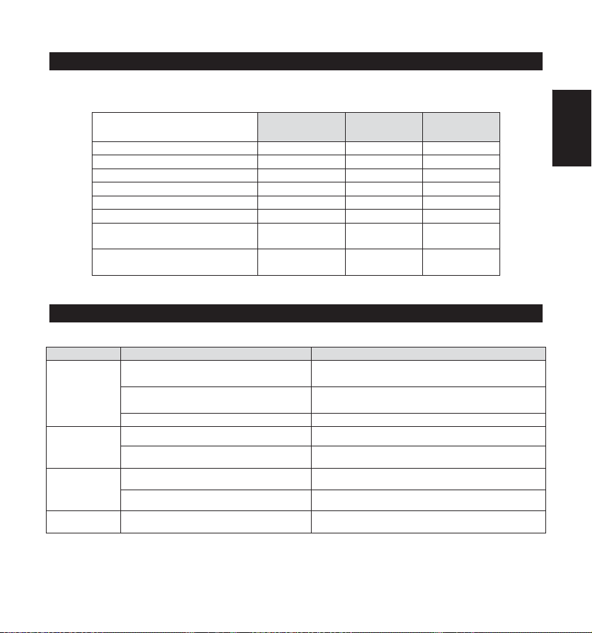
Ricerca Guasti
Questo paragrafo descrive le possibili problematiche del prodotto e le rispettive soluzioni.
Ricordarsi di effettuare tutti i controlli preliminari descritti in questo manuale prima di fare riferimento
alla tabella Ricerca Guasti che segue.
Effettuare una ispezione preliminare del rivelatore per rilevare eventuali danni meccanici,
connessioni allentate, o cavi danneggiati.
Controllare le connessioni alla sorgente di alimentazione e verificare che ci sia la corretta
alimentazione al rivelatore.
Anomalia Spiegazione Soluzione
La configurazione dei rivelatori
non viene accettata dalla
centrale ProSYS
Segnalazione di Tamper
(manomissione) utilizzando il
modo di collegamento BUS
ProSYS
Segnalazione di Tamper
(manomissione) nel modo di
funzionamento Relé o BUS
La Procedura di Test Sensori
(Prova di Movimento) non
viene attivata dalla tastiera
della centrale ProSYS
Il LED verde non si accende
durante la prova di movimento
(test sensori). Il canale
Microonda (MW) non funziona
(nessuna rilevazione)
Problema di
configurazione
dell’indirizzo ID del
rivelatore
Connessione del
Tamper errata per il
funzionamento in modo
BUS ProSYS
L’interruttore del
Tamper è
probabilmente aperto
Il codice inserito è
errato.
1. LuNAR è
configurato (via
centrale ProSYS) per
disabilitare la sezione
microonda a sistema
disinserito
2. Il LuNAR sta
operando in modo
Esclusione Microonda a
causa di un’anomalia
del canale microonda
(MW)
Scollegare tutte le sorgenti di
alimentazione (rete elettrica e
batterie), verificare la
configurazione dell’indirizzo ID dei
rivelatori e ridare alimentazione.
Verificare che i microinterruttori 8 e
9 siano in posizione ON.
Verificare che la molla di chiusura
dell’interruttore del tamper del
contenitore sia posizionata
correttamente.
Inserire un codice abilitato ad
effettuare la procedura di test
sensori.
Il funzionamento è corretto, il LED
verde della microonda non deve
illuminarsi.
Togliere l’alimentazione al sensore
e darla nuovamente, se il problema
persiste, sostituire il rivelatore.
Ind. LuNAR RK200DTG3 - Guida all’installazione 22
Page 47

Specifiche Tecniche
Copertura
Altezza di installazione variabile
Frequenza sezione MW
Tipo di segnale emesso MW
Potenza Max. irradiata MW
Immunità RFI
Alimentazione
Assorbimento di corrente
Contatti di allarme NC, 100mA, 24 V
Contatti tamper NC, 500mA, 24 V
Tempo di allarme
Tempo di preriscaldamento
Filtro ottico per la protezione
contro le luci bianche
Temp. di funzionamento
Temp. di funzionamento
certificate
Temp. di stoccaggio
Livello di prestazione
Dimensioni (Altezza x Diametro)
Ind. LuNAR RK200DTG3 è conforme alle normative europee PD6662, EN50131-1 e EN50131-2-4
Grado 3, Classe II ed è certificato IMQ II Livello di prestazione.
Il diagramma di copertura include 192 elementi sensibili
(96 zone) suddivisi in 3 ottiche. Ogni ottica ha 4 posizioni
per la regolazione verticale per adattarsi all’altezza di
installazione o a coperture personalizzate.
360° e 18m di diametro. Al di sotto dei 3.7 metri di altezza
di installazione il diametro di copertura di 18 metri inizia a
diminuire fino ad arrivare a 15 metri ad una altezza di
installazione di 2.7 metri.
Da 2.7m a 8.6m, 4 posizioni per ogni ottica in funzione
dell’altezza di installazione
10.587 GHz.
Tipo pulsato
13.5 dBm erp
Conforme alla normativa EN50130-4
Da 9 V a 16 V
20mA a 12 V , 30mA a 16 V , Massimo 40mA con tutti
i LED accesi.
2.2 secondi
2 minuti
Lenti di Fresnel pigmentate
Da -20° C a 55° C
Da 5° C a 40° C
Da -20° C a 60° C
II° Livello IMQ
99mm x 194mm
Italiano
Ind. LuNAR RK200DTG3 - Guida all’installazione 23
Page 48

Ind. LuNAR RK200DTG3 - Guida all’installazione 24
Page 49

DDTT AAMM GGrraauu 3
MMooddeelloo:: RRKK220000DDTTGG33
3
DDeetteeccttoorr ppaarraa iinnssttaallaaççããoo eemm tteettooss aallttooss
GGuuiiaa ddee iinns
sttaallaaççããoo
Português
Page 50

Descrição Geral
O Industrial LuNAR DT AM Grau 3 (RK200DTG3) é um detector de teto de Dupla Tecnologia com uma
altura de montagem de até 8.6m (28 pés), que incorpora a Tecnologia (ACT™) Anti-Cloak™ do RISCO
Group. O detector possui um método de Processamento Inteligente do Sinal Digital que ajusta
automaticamente o limiar do alarme e a verificação do contador de pulsos, segundo a real velocidade de
passagem do intruso e fatores ambientais, proporcionando uma melhor detecção e imunidade a falsos
alarmes.
O Ind. LuNAR RK200DTG3 pode funcionar como um detector convencional de relé conectado a
qualquer painel de controle, ou como um acessório direcionável do BUS quando conectado ao painel de
controle do ProSYS do RISCO Group, através do BUS RS485.
Características do Ind. LuNAR RK200DTG3
♦ PD6662, EN50131-1, EN50131-2-4 Grau 3
♦ Detector com Dupla Tecnologia (Microondas + Infravermelho Passivo) com Tecnologia Anti-Cloak™
♦ Altura de montagem de até 8.6 m (28 pés)
♦ Padrão do diâmetro de cobertura de 360° por 18m (60 pés)
♦ 3 canais de Infravermelho Passivos para uma cobertura ajustável para cada necessidade
♦ Processamento Inteligente do Sinal Digital – verificação do alarme e limiares de decisão ajustados
segundo a atual velocidade de passagem do intruso
♦ Resistências de fim de linha triplas embutidas, selecionável através de jumper.
♦ Anti-Mascaramento através de Infravermelho Ativo, atendendo aos requisitos EN50131
♦ Tampers de teto e tampa
♦ Configuração “Green” – para desativar o Microondas quando o sistema estiver desarmado
♦ Opto-relés para baixo consumo de corrente e longo ciclo de vida
♦ Autoteste local e remoto
♦ Entrada de SET (ajuste) remoto
♦ Entrada para habilitar/desabilitar o controle remoto
♦ Ajuste das lentes para maior eficiência da cobertura do Infravermelho Passivo
♦ Ajuste do Alcance de Microondas manualmente (Através de Trímmer - Analógico) ou remotamente
(configuração digital)
♦ Indicação de Problemas (por LEDs ou via comunicação)
♦ 3 LEDs tricolores para um teste de caminhada fácil
♦ Avançado Controle Remoto e Diagnóstico
♦ Consumo de Corrente reduzido quando conectado ao ProSYS do RISCO Group
Ind. LuNAR RK200DTG3 – Guia de Instalação 2
Page 51

Características de Controle Remoto e Diagnóstico*
♦ Ajuste remoto do canal de microondas permite habilitar o teste de caminhada por uma
pessoa.
♦ Ferramentas de diagnóstico incluem a leitura da voltagem de entrada ao detector e o
estado de cada canal de Infravermelho Passivo do canal de microondas (voltagem do
sinal e níveis de ruído), canal AM (voltagem do sinal), verificação da versão do Software.
♦ Apresentação remota e controle da configuração do detector: ajuste do microondas, ACT
Ativo / Inativo, LEDs Ativo / Inativo.
♦ Indicador remota de problemas (Passa / Falha) para o Infravermelho Passivo, o
microondas e a entrada de alimentação de energia
♦ Controle da anulação do canal de Microondas (durante problema de Microondas) e de
desabilitar o canal de Microondas durante o Desarme ("Green Line") quando conectado
ao ProSYS.
*Através do Controle Remoto Infravermelho Bidirecional opcional, ou do Software Upload/
Download do ProSYS e o teclado numérico.
Método de Detecção
A detecção do Ind. LuNAR RK200DTG3 está baseada em:
♦ IVP (Infravermelho Passivo) – que responde as mudanças na radiação de Infravermelho
causadas quando um intruso cruza a área protegida.
♦ Microondas – que transmite sinais e analisa as mudanças de freqüência do eco refletido
de um intruso usando o Efeito Doppler.
Um ALARME é iniciado somente quando ambas as tecnologias são acionadas simultaneamente
(exceto em certas situações no modo ACT – ver página 4 – “Como Funciona o ACT™”), reduzindo
assim em grande escala a possibilidade de falsos alarmes.
Português
Ind. LuNAR RK200DTG3 – Guia de Instalação 3
Page 52

Como Funciona o ACT™
A Tecnologia Anti-Cloak™ (ACT™) proporciona os benefícios de um detector DT (Dual
Technology – Dupla Tecnologia) enquanto evita as suas desvantagens. Esta inovação (Patente
Pendente) criou um novo padrão para os detectores.
A Dupla Tecnologia, uma combinação de Infravermelho Passivo + Microondas, foi um importante
crescimento para a indústria da segurança... Mas possui 2 grandes pontos fracos:
A emissão de Infravermelho dos intrusos pode ser bloqueada, evitando a detecção.
A sensibilidade do Infravermelho Passivo é reduzida quando a temperatura do ambiente da área
protegida se aproxima à temperatura do corpo.
Respondendo às solicitações de seus clientes para solucionar estes problemas urgentes, o RISCO
Group desenvolveu a ACT™ - uma revolucionária solução anti-camuflagem.
O ACT™ impede que o sistema de alarme seja anulado – neutralizando as tentativas de camuflar
a radiação de Infravermelho. Usando algoritmos de reconhecimento de padrão único, a ACT™
distingue entre o sinal fraco de Infravermelho de um intruso em movimento e o ruído de fundo e as
interferências térmicas que podem causar falsos alarmes.
Uma vez verificada a presença de um intruso, a ACT™ troca automaticamente o sistema do modo
de dupla tecnologia Infravermelho Passivo/Microondas para o modo de canal único de Microondas
por um período de tempo predeterminado, com a finalidade de ativar um alarme usando o canal
Microondas, e depois retorna ao modo de canal duplo.
No segundo caso, quando a temperatura do ambiente se aproxima à temperatura do corpo, o
ACT™ passa a detecção somente por microondas.
Oferecendo uma capacidade de detecção excepcionalmente alta, assim como imunidade a falsos
alarmes, a ACT™ frustra até aos mais sofisticados intrusos.
Ind. LuNAR RK200DTG3 – Guia de Instalação 4
Page 53

Opções de Configuração do Ind. LuNAR RK200DTG3
O Ind. LuNAR RK200DTG3 pode ser configurado e/ou diagnosticado remotamente através de
uma das seguintes opções:
Modo ACT
LEDs
Sensibilidade Microondas
Diagnóstico
Estado/Problema/Informes
Configuração
Manual
Controle
Remoto
Controle Bus
ProSYS
(Através do
trimmer)
-
-
de Informação
Diagnóstico Antimáscara
Anulação Microondas
Microondas Desativadas ao
Desarmar ("Green Line")
- -
- -
- -
Visualização dos LED’s
Os três LEDs tricolores no Ind. LuNAR RK200DTG3, operam como descrito a seguir:
LED ESTADO SIGNIFICADO
Alarme do detector (detecção
Constante
Vermelho
Piscando em baixa freqüência
Infravermelha Passivo e Microondas
simultâneo)
Indica mau funcionamento da comunicação
com o ProSYS
Piscando em alta freqüência Detecção Anti-máscara
Verde
Laranja
Todos os
LEDs
Constante Detecção microondas
Piscando Problema no canal de Microondas
Constante Detecção Infravermelho Passivo
Piscando Problema no canal Infravermelho Passivo
Piscando com mudança de
cor
Ao ativar-se
Ind. LuNAR RK200DTG3 – Guia de Instalação 5
Português
Page 54

INSTALAÇÃO
Passos preliminares:
♦ Antes de instalar, estude cuidadosamente o espaço a ser protegido para escolher a
localização exata da unidade para a melhor cobertura possível.
♦ Nunca instale o LuNAR num ambiente que cause uma condição de alarme em uma das
tecnologias.
♦ Evite as instalações onde máquinas rotativas (por exemplo, ventiladores) estejam
normalmente em operação dentro da área de cobertura. Aponte a unidade para longe de
vidros expostos ao exterior e a objetos que podem mudar rapidamente de temperatura.
♦ Não monte o detector com luz direta do sol nem perto de nenhuma fonte de calor. Os
setores de detecção devem apontar em direção a uma parede, ou a um assoalho mas
nunca em direção a janelas ou cortinas. A superfície de instalação deve ser sólida, lisa e
sem vibrações.
♦ Elimine a interferência de fontes exteriores próximas.
♦ Para uma ótima detecção, selecione uma localização propensa a interceptar um intruso
movendo-se através do padrão de cobertura.
♦ A altura de montagem recomendada, que permite um diâmetro de detecção de 18m (60
pés), é de 3.7m até 8.6m.
♦ O detector deve ser montado no teto, preferentemente no centro do recinto.
Ind. LuNAR RK200DTG3 – Guia de Instalação 6
Page 55

A típica cobertura de detecção do Ind. LuNAR RK200DTG3 e a altura de instalação são
ilustradas abaixo:
Vista Superior
0 7 13 20 26 3030 26 20 13 7
ft
m
5
4
3
2
1
m
3
2
1
Vista Lateral
Vista Lateral
Altura de instalação de 5,5 m / 18 ft
02468998642
Altura de i nstalação de 3,7 m / 12 ft
0 7 13 20 26 3030 26 20 13 7
02468998642
0 7 13 20 26 3030 26 20 13 7
02468998642
18m/60"
Ind. LuNAR RK200DTG3 – Guia de Instalação 7
NOTAS:
• Quando o detector Ind. LuNAR RK200DTG3 é
instalado em um local que contenha uma
quantidade de fatores que causem interferência,
a detecção por Microodas pode ser afetada
• As distâncias podem variar de acordo com as
condições térmicas ambientais.
Português
m
Page 56

Processo de Instalação:
Para abrir o detector (Figura 1), retire a tapa inserindo uma chave de fenda (1) no encaixe entre a
tampa de proteção e a capa. A capa permanece unida à base do detector.
Usando uma chave de fenda Philips, libere o parafuso superior da tapa (2) e puxe suavemente
para cima a tapa superior do detector.
2
1
FIGURA 1
Ind. LuNAR RK200DTG3 – Guia de Instalação 8
Page 57

Libere o parafuso que mantém o PCB (Figura 2) localizado no lado direito do PCB (1), puxe
suavemente os dois clipes de liberação (2) para fora e retire o PCB.
Não toque nos
sensores de
FIGURA 2
Infravermelho
Passivo!
Português
Não Retire os filtros contra luz branca
instalados nos sensores de Infravermelho,
eles são essenciais para evitar falsos alarmes
causados por luz branca
Se requerido, abra (Figura 3) o furo pré-marcado dos canais de fiação usando um alicate de corte
(1, 2) e os furos pré-marcados na tampa posterior (3, 4) usando uma chave de fenda.
Ind. LuNAR RK200DTG3 – Guia de Instalação 9
Page 58

FIGURA 3
Introduza o cabo através da abertura do cabo (Figura 4) e conecte os cabos desejados como
descrito no “Passo 4- Fiação”.
Ind. LuNAR RK200DTG3 – Guia de Instalação 10
Page 59

FIGURA 4
Monte a tampa posterior em sua localização final (Figura 5) usando os três parafusos de
montagem e sele os furos abertos remanescente com um material impermeabilizante.
NOTA:
Quando for utilizada uma única caixa de passagem, use
2 parafusos adicionais para montar a base na caixa.
O tamper posterior não pode ser usado neste caso!
FIGURA 5
Retorne o PCB à sua localização anterior e verifique que tudo está bem assegurado pelos clipes
de sustentação e pelo parafuso.
Execute o ajuste da lente e a configuração dos Interruptores Dip como descrito em “Ajuste de
Lentes” nesta página e “Configuração dos Interruptores Dip” na página 15.
Ind. LuNAR RK200DTG3 – Guia de Instalação 11
Português
Page 60

Monte a tampa superior na base do detector.
Aperte o parafuso central da tampa superior.
Recoloque a tampa de proteção do detector.
NOTA:
Para um tamper de teto, fixe o parafuso do tamper
traseiro, como demonstrado na figura 5
Ajuste de Lentes:
O LuNAR tem três lentes Fresnel unidas à tampa, localizadas em mangas protetoras do sensor.
Ajuste a posição das lentes baseando-se na altura de montagem em teto como segue:
Pressione os 2 clipes que unem a manga (Figura 6) à tampa do detector, e retire suavemente a
manga.
FIGURA 6
Ind. LuNAR RK200DTG3 – Guia de Instalação 12
Page 61

Retire as lentes da manga (Figura 7) levantando-a suavemente dos pinos de sustentação que a
asseguram nos lados do protetor de elemento piroelétrico.
FIGURA 7
Coloque os dois pinos, que estão localizados em ambos os lados do protetor de elemento
piroelétrico ranhuras apropriadas na lente. Use a seguinte tabela para selecionar a desejada
posição da lente.
Português
Retorne o protetor de elemento piroelétrico a seu lugar na tampa dianteira do detector.
Repita os passos 1 a 5 para as 2 lentes remanescentes.
Ind. LuNAR RK200DTG3 – Guia de Instalação 13
Page 62

NOTAS:
• Abaixo da altura de montagem de 3.7m, o diâmetro de cobertura começa a diminuir, e na altura de
2.7m, o diâmetro de cobertura é de 15m (50 pés).
• Para uma cobertura personalizada, é possível fixar a posição de cada lente numa altura diferente,
segundo as condições de instalação.
• Todos os detectores da RISCO Group que possuem o sistema de anti-máscara através de
Infravermelho Ativo, possuem uma proteção contra luz branca diretamente em cima do sensor
piroelétrico, isso não é uma proteção para transporte. Não retire a proteção contra luz branca, pois
isso além de não melhorar o desempenho, torna o detector passivo de disparos falsos gerados por
rajadas de luz.
Ind. LuNAR RK200DTG3 – Guia de Instalação 14
Page 63

Jumpers de controle
ENTRADA DE
CONTROLE
REMOTO/SET
Usado para determinar a polaridade das entradas externas.
12V: Para ativar o funcionamento é necessário aplicar 12V.
GND ou Desligado não tem influência no estado do
Controle remoto/SET.
(veja as configurações dos dipswitches no modo Relé)
0V: Para ativar o funcionamento é necessário aplicar GND.
12v ou Desligado não tem influência no estado do Controle
remoto/SET.
(veja as configurações dos dipswitches no modo Relé)
Português
Ind. LuNAR RK200DTG3 – Guia de Instalação 15
Page 64

JUMPERS
RESISTÊNCIA
EOL
FAULT/A M EOL
JUMPERS
12K
No
Resistor
(Default)
Os jumpers são usados ao conectar-se o detector
a uma Zona DEOL ou TEOL. Os jumpers
permitem a seleção de resistências EOL de
TAMPER, ALARME (1K, 2.2K, 4.7K, 5.6K
ou6.8K), de acordo com as configurações do
painel de controle. Um jumper duplo adicional
permite a conexão de uma resistência EOL de
12K FALHA/AM (ver Diagrama de Resistências
EOL).
Siga o diagrama de conexão do bloco de
terminais ao conectar o detector a uma Zona de
Duplo/Triplo Fim-de-Linha (DEOL/TEOL).
Diagrama Esquemático das Resistências EOL
Configuração dos Interruptores DIP
O Ind. LuNAR RK200DTG3 tem um interruptor DIP de 9 posições que muda de funcionalidade
para uso no modo de operação Relé ou BUS. Configure o interruptor DIP de acordo com as
tabelas abaixo:
Configuração Predeterminada em Fábrica:
Ind. LuNAR RK200DTG3 – Guia de Instalação 16
ON
123456789
Page 65

Configuração do Modo Relé
(Interruptor DIP 6=OFF)
:
Número do
Interruptor DIP
1
2
3
4
5
6
7
Descrição
Usado para determinar a operação do ACT
Interruptor DIP ON: ACT está ativado
Interruptor DIP OFF: ACT está desativado (predeterminado em fábrica)
Usado para determinar a operação dos LEDs do detector
Interruptor DIP ON: LEDs estão ativados (predeterminado em fábrica)
Interruptor DIP OFF: LEDs estão desativados
Usado para determinar a função "Green Line" (veja nota abaixo)
Interruptor DIP ON: "Green Line" está ativada
Interruptor DIP OFF: "Green Line" está desativada (Ajuste de fábrica)
Usado para determinar o tipo de Autoteste (veja nota abaixo)
Interruptor DIP ON: Autoteste Local:
No caso de falhar o autoteste local, o Relé FALHA/AM é ativado por um período de
2.5 segundos.
Interruptor DIP OFF: Autoteste Remoto (predeterminado em fábrica):
No caso de o autoteste remoto ser bem sucedido, os Relés Alarme são ativados por
um período de 5 segundos. No caso de o teste falhar, o Relé FALHA/AM é ativado
por um período de 2.5 segundos.
Usado para determinar se o Anti-Mascaramento por Infravermelho Ativo está ativado.
(veja nota abaixo)
Interruptor DIP ON: Ativado
Interruptor DIP OFF: Desativado (predeterminado em fábrica)
IMPORTANTE:
Caso o Jumper do AM esteja habilitado através do Dipswitch 5, a tampa do detector deve
ser colocada dentro de 1 minuto após a ligação da alimentação elétrica. Caso o detector já
esteja alimentado eletricamente e o Dipswitch 5 esteja ligado, a unidade deve ter a sua
alimentação desligada e re-ligada, para re-iniciar a calibração do sistema de Anti-Máscara
(AM).
Usado para determinar o modo de conexão do detector
Interruptor DIP OFF: Modo Relé
Usado para determinar se a comunicação do Controle Remoto (RC) está ativada ou
desativada.
Interruptor DIP ON: A comunicação do RC está sempre ativada.
Português
Ind. LuNAR RK200DTG3 – Guia de Instalação 17
Page 66

Interruptor DIP OFF: A comunicação do Controle Remoto depende da voltagem
aplicada ao bloco de terminais “RC” (Ajuste de fábrica)
Quando um sinal de ativação é aplicado à entrada do Controle Remoto do bloco de
terminais, o controle remoto estará ativado.
IMPORTANTE:
Passe o interruptor 7 para “OFF” depois da instalação e quando sair do local por razões de
segurança. Isto evitará o uso não-autorizado de uma unidade de controle remoto que pode
ser utilizada para desativar o detector.
8-9
Não Aplicável – Dipswitches desligados
IMPORTANTE:
Desconecte todas as fontes de energia antes de configurar os interruptores DIP do Ind.
LuNAR RK200DTG3. Ligue as fontes de energia ao completar a configuração!
NOTE:
Consulte os ajustes de do bloco de terminais para detalhes de ativação.
Configuração do Modo BUS
(Interruptor DIP 6=ON):
Número do
Interruptor
Descrição
DIP
Usado para configurar o número de ID do detector. (Ver Tabela 1)
1-5
Configure o número de ID da mesma maneira como para qualquer outro acessório do
ProSYS.
6
Usado para determinar o modo de conexão do detector.
Interruptor DIP ON: Conexão ProSYS– Configuração BUS
NOTE:
Ao ser ativado ou em operação normal, o LuNAR espera 10 segundos para a comunicação
com o ProSYS. Pode ocorrer um problema de comunicação devido à má fiação, endereço
errado, ou se o ProSYS não foi devidamente configurado; todos os LEDs piscarão
continuamente até ser solucionado o problema.
7
8-9
Não aplicável (a comunicação RC é automaticamente ativada ao passar para o modo
teste de caminhada no ProSYS e desativada em caso contrário).
Interruptor DIP ON: A fim de habilitar o detector para informar o estado do tamper ao
ProSYS.
BUS ADDRESS
ON
1234567
BUS
MODE
TAMPER
N/A
9
8
Ind. LuNAR RK200DTG3 – Guia de Instalação 18
Page 67

Tabela 1: Configuração do ID para a conexão BUS
ID 1 2 3 4 5 ID 1 2 3 4 5
OFF OFF OFF OFF OFF
01
ON OFF OFF OFF OFF
02
OFF ON OFF OFF OFF
03
ON ON OFF OFF OFF
04
OFF OFF ON OFF OFF
05
ON OFF ON OFF OFF
06
OFF ON ON OFF OFF
07
ON ON ON OFF OFF
08
OFF OFF OFF ON OFF
09
ON OFF OFF ON OFF
10
OFF ON OFF ON OFF
11
ON ON OFF ON OFF
12
OFF OFF ON ON OFF
13
ON OFF ON ON OFF
14
OFF ON ON ON OFF
15
ON ON ON ON OFF
16
OFF OFF O FF OFF ON
17
ON OFF OFF OFF ON
18
OFF ON OFF OFF ON
19
ON ON OFF OFF ON
20
OFF OFF ON OFF ON
21
ON OFF ON OFF ON
22
OFF ON ON OFF ON
23
ON ON ON OFF ON
24
OFF OFF OFF ON ON
25
ON OFF OFF ON ON
26
OFF ON OFF ON ON
27
ON ON OFF ON ON
28
OFF OFF ON ON ON
29
ON OFF ON ON ON
30
OFF ON ON ON ON
31
ON ON ON ON ON
32
Português
Ind. LuNAR RK200DTG3 – Guia de Instalação 19
Page 68

Blocos de Terminais
BLOCO TERMINAL 1 DESCRIÇÃO
+12V (RED)
- (BLK)
Voltagem de entrada positiva (+) da fonte de alimentação
Comum à fonte de alimentação do painel de controle
BUS (GRN) Usado para comunicação de dados com o ProSYS
BUS (YEL)
SET ∗
Usado para comunicação de dados com o ProSYS
Usado para ativar/desativar remotamente o detector.
Quando um sinal de ativação (ver os ajustes de ativação do Jumper de RC/SET)
é aplicado à entrada do LED no bloco de terminais os LEDs serão desativados.
Os LED’s de AM serão desabilitados(Se o Dipswitch 5 de AM for ajustado em
ON)
O módulo de Microondas é habilidado (Se o Dipswithc 3 de GreenLine for
ajustado como ON).
Removendo o sinal de ativação será causado um teste Self Test (Se o Dipswith 4
de Self Test estiver previamente ajustado na posição OFF).
RC ∗
(CONTROLE
REMOTO)
Usado para ativar/desativar a comunicação do controle remoto, somente quando
o interruptor DIP 7 estiver em “OFF”.
Quando um sinal de ativação (ver Jumper de controle dos LED’s) é aplicado à
entrada do RC no bloco de terminais, o Controle Remoto será ativado.
Nota: O interruptor DIP 7em “ON” habilita constantemente a comunicação do
RC.
IMPORTANTE:
Passe o interruptor 7 para “OFF” depois da instalação e quando sair do local por razões de
segurança. Isto evitará o uso não-autorizado de uma unidade de controle remoto que pode ser
utilizada para desativar o detector.
∗
Não relevante no modo BUS
BLOCO TERMINAL 2 DESCRIÇÃO
AM/FAULT
(AM/Falha)
Saída normalmente fechada
A saída AM/FALHA se abre nos seguintes eventos:
O detector é encoberto (o ALARME também se abre neste caso)
O Autoteste falhou
A voltagem de entrada é baixa (6VDC-8VDC)
TAMPER
ALARM
Saída normalmente fechada
Saída normalmente fechada
(Alarme)
Ind. LuNAR RK200DTG3 – Guia de Instalação 20
Page 69

Teste de caminhada
NOTA:
Para realizar o teste de caminhada, primeiro ative os LED’s.
Dois minutos depois de ativado (período de aquecimento), faça o teste de caminhada no detector
em toda a área protegida para verificar a correta operação do detector e observar o LED tricolor. A
margem do padrão de microondas é determinada pela ativação do primeiro LED vermelho (ambos
os LED’S de Infravermelho Passivo e Microondas são acionados).
NOTA:
Se os LED’s Infravermelho Passivo/Microondas não se
LIGAM, isto provavelmente significa que há um problema
com a posição das lentes (PIR), ou com o ajuste do
Microondas!
Ajuste a sensibilidade do microondas girando o potenciômetro do PCB (usando uma chave de
fenda), ou usando o dispositivo de Controle Remoto. Faça o teste de caminhada da unidade em
todas as direções para determinar todos os limites do padrão de detecção.
NOTA:
Ajuste o Microondas à configuração mais baixa possível que
ainda proporcione suficiente cobertura a toda a área
protegida!
Ao usar o dispositivo de Controle Remoto, recomenda-se realizar o Autoteste do LuNAR; para
maiores instruções dirija-se às Instruções do Controle Remoto.
Ao completar a instalação e as fases de teste, certifique-se de que todos os interruptores estejam
em suas desejadas posições.
Português
IMPORTANTE:
Passe o interruptor 7 para “OFF” depois da instalação e
quando sair do local por razões de segurança. Isto evitará
o uso não-autorizado de uma unidade de controle remoto
que pode ser utilizada para desativar o detector.
Ind. LuNAR RK200DTG3 – Guia de Instalação 21
Page 70

Localização e Solução de Problemas
Esta seção descreve os possíveis problemas do sistema e suas soluções.
Realize sempre as seguintes verificações preliminares antes de referir-se à tabela de solução de
problemas.
Realize uma inspeção visual completa do LuNAR para observar sinais de danos mecânicos,
conexões perdidas ou cabos rompidos.
Verifique as conexões da fonte de energia de entrada CA.
Problema Causa Solução
A configuração dos
detectores do ProSYS
falhou/não foi aceita pelo
sistema
Indicação de Tamper
enquanto opera no modo
BUS
Indicação de Tamper no
modo Relé ou BUS
Teste de Caminhada não
pode ser iniciado através
do teclado numérico do
ProSYS
O LED Verde não funciona
durante a Prova de
Movimento – o canal de
Microondas não funciona
Problema de
configuração do ID
Mau funcionamento da
conexão do Tamper
Tamper provavelmente
não fechado
Código errado Introduza o código apropriado
O Ind. LuNAR
RK200DTG3 está
configurado (através do
ProSYS) para
“Microondas desativado
ao DESARMAR”
durante o modo
DESARMAR do
ProSYS
O Ind. LuNAR
RK200DTG3 está
operando no modo
Anulação devido ao
"Modo Anulação do
Canal Microondas”
Desconecte todas as fontes de
energia, configure os ID’s
requeridos e re-conecte
novamente
Verifique se ambos os DIPs 8 e
9 estão na posição ON
Verifique visualmente se o
tamper do teto e a mola estão
instalados corretamente
Comportamento normal
Reajuste o detector.
Se o problema no canal de
Microondas voltar a ocorrer,
deve-se substituir o detector por
um novo
Ind. LuNAR RK200DTG3 – Guia de Instalação 22
Page 71

Especificações
Cobertura
Altura Variável de Montagem
Imunidade RFI
Voltagem de operação
Consumo de corrente
Contatos de Alarme e AM
Contatos do Tamper
Tempo de Alarme
Tempo de aquecimento
Filtragem ótica para proteção de
luz branca
Temperatura de operação
Temperatura de armazenamento
Dimensões (Altura x Diâmetro)
O detector Ind. LuNAR RK200DTG3 é apropriado para uso em instalações que cumprem com
PD6662, EN50131-1 e EN50131-2-4 Grau 3, Classe II.
O padrão de cobertura consiste de 192 Segmentos (96
facetas Fresnel) divididos em 3 seções de lentes. Cada
seção de lente tem 4 posições verticais ajustáveis para
altura variável de montagem e para uma cobertura
configurada de acordo com as necessidades do usuário.
Diâmetro de 360° por 18m (60’). Quando o detector é
instalado em uma altura interior a 3,7 metros, o diâmetro
da cobertura começa a ser reduzido até 15 metros (50ft).
Deste 2.7m até 8.6m (9’ até 28’), 4 posições de lentes de
acordo com a altura de instalação
De acordo com EN50130-4
9 a 16VDC
20mA a 12VDC, 30mA a 16 VDC, Máximo 40mA com
todos os LEDs ativados.
Opto-relé NC, 100mA, 24 VDC
NC, 500mA, 24 VDC
2.2 segundos
2 minutos
Lentes pigmentadas Fresnel
-20° C a 55° C (-4° F a 131° F)
-20° C a 60° C (-4° F a 140° F)
99mm x 194mm (3.9’’x 7.6’’)
Português
Ind. LuNAR RK200DTG3 – Guia de Instalação 23
Page 72

Ind. LuNAR RK200DTG3 – Guia de Instalação 24
Page 73

MMooddèèllee:: RRKK220000DDTTGG33
GGuuiiddee dd''iinnssttaallllaattiioonn
dduu DDéétteecctteeuurr ppoouurr hhaauutt ppllaaffoon
DDTT AAMM GGrraaddee 3
3
ndd
Françias
Page 74

Description générale
L'Industrial LuNAR DT AM Grade 3 (RK200DTG3) est un détecteur double technologie, à monter au
plafond ; il peut être installé jusqu'à une hauteur 8,6 m (28 pieds), et intègre la Technologie Anti-Cloak™
(ACT™) de RISCO Group. Le détecteur dispose d'une technologie de traitement intelligent de signaux
numériques, qui ajuste automatiquement le seuil des alarmes ainsi que la vérification du comptage des
impulsions selon la vitesse réelle de passage de l'intrus et en fonction de facteurs environnementaux, ce
qui assure une excellente détection et une grande immunité aux fausses alarmes.
L' Ind. LuNAR RK200DTG3 peut fonctionner comme un détecteur ordinaire à relais connecté à toute
centrale, ou comme un détecteur adressable à BUS lorsqu'il est connecté à la centrale ProSYS de
RISCO Group via le BUS RS485.
Caractéristiques de l'Ind. LuNAR RK200DTG3
♦ PD6662, EN50131-1, EN50131-2-4 Grade 3
♦ Détecteur adressable, double technologie, intégrant la technologie Anti-Cloak™
♦ Hauteur d'installation jusqu'à 8,6 m (28 pieds)
♦ Couverture : 360
♦ 3 canaux IRP indépendants qui assurent une couverture sur mesure.
♦ Traitement intelligent des signaux numériques – la vérification des alarmes ainsi que les seuils
de décision sont ajustés selon la vitesse réelle de passage de l'intrus
♦ Triples résistances de fin de ligne (EOL) intégrés, choix de la valeur par cavalier
♦ IR actifs d'anti-masquage pour répondre aux exigences de la norme EN50131
♦ Autoprotecion à l’arrachement et à l’ouverture
♦ Technologie "GreenLine" – pour désactiver l’hyperfréquence lorsque les lieux sont occupés
♦ Relais optique – assure une consommation minime d'électricité et une grande durée de vie
♦ Auto test à distance et auto test local
♦ Entrée SET (indication de Mise en service)
♦ Entrée RC (pour contrôle de la télécommande)
♦ La couverture IRP est optimisée en faisant glisser les lentilles
♦ Réglage de la portée des hyperfréquences (trimmer analogique) manuel ainsi qu'à distance
(réglage numérique)
♦ Indication de dérangement (par des LED ou via une communication)
♦ 3 LED tricolores permettent d'exécuter facilement un test de marche
♦ Télécommande et diagnostics avant gardiste
♦ Consommation électrique minime lorsqu'il est connecté au ProSYS de RISCO Group
0
pour 18 m (60 pieds) de diamètre
2 Guide d'installation de l'Industrial LuNAR RK200DTG3
Page 75

Caractéristiques de la télécommande et des diagnostics *
♦ Le réglage à distance des hyperfréquences permet le test de marche
♦ Les outils de diagnostic comprennent la lecture de la tension d'entrée du détecteur ainsi que
le statut de chaque canal IRP et du canal HF (tension des signaux et niveaux de bruit), du
canal AM (tension du signal), et la vérification de la version firmware
♦ Affichage et contrôle à distance des réglages des détecteurs : réglage HF, Marche/Arrêt de
l’ACT, Marche/Arrêt des LED.
♦ Indication de dérangement à distance (Correct/Échec) de l’IRP, de l’HF et de l'alimentation
♦ Contournement du contrôle de l’HF (pendant les dérangements HF) et désactivation des HF
en mode Désarmé ("GreenLine") lorsque l'appareil est connecté au ProSYS.
*Via la télécommande bi-directionnelle IR (en option), le logiciel Upload/Download ou le clavier de
la ProSYS.
Méthode de détection
La détection de l'Ind. LuNAR RK200DTG3 est basée sur :
♦ IRP (Infra Rouges Passifs) - il répond aux variations des radiations IR causées
lorsqu'un intrus passe dans la zone protégée.
♦ HF (Hyperfréquence) - il transmet des signaux et analyse les variations de la fréquence de
l'écho réfléchi par un intrus, il utilise l'effet Doppler.
Une ALARME est transmise seulement lorsque les deux technologies déclenchent simultanément
(sauf pour certaines situations dans le Mode ACT voir la page 4 – “Comment l'ACT™ fonctionne”), ce
qui réduit sensiblement les possibilités de fausses alarmes.
Françias
Guide d'installation de l'Industrial LuNAR RK200DTG3 3
Page 76

Comment l'ACT™ fonctionne
La technologie Anti-Cloak™ (ACT™) donne les avantages de la DT (double technologie) tout en
évitant ses inconvénients. Cette innovation brevetée a créé un nouveau standard pour les détecteurs.
La double technologie, en combinant l’IRP + l’HF, a été un important développement pour l'industrie de
la sécurité ... mais, elle présente 2 graves faiblesses :
Des vêtements qui bloquent les émissions IR utilisés par des intrus permettent d'éviter la détection de
ces derniers.
La sensibilité de l’IRP est réduite lorsque la température ambiante de la zone protégée est proche de la
température du corps.
Pour répondre aux demandes de sa clientèle de résoudre ces problèmes, RISCO Group a développé
l'ACT™ - une solution révolutionnaire d’anti-camouflage.
L'ACT™ évite que le système d'alarme soit contourné, en neutralisant les tentatives de camouflage
des radiations IR. Grâce à l’utilisation d'algorithmes uniques de discernement, l’ACT™ fait la distinction
entre le faible signal IR d'un intrus se déplaçant et le bruit de fond et les interférences thermiques qui
pourraient causer des fausses alarmes.
Dès que la présence d'un intrus camouflé est détectée, l'ACT™ fait basculer le système
automatiquement du mode à deux canaux IRP/HF au mode un seul canal HF pendant une durée
prédéterminée, afin de déclencher une alarme en se servant du canal HF, et ensuite il revient au mode
à deux canaux.
Dans le second cas, lorsque la température ambiante est proche de la température du corps, l'ACT™
passe à la détection uniquement par hyperfréquence.
Offrant des capacités de détection significativement meilleures ainsi qu’une grande immunité aux
fausses alarmes, ACT™ déjoue même les cambrioleurs les plus aguerris.
4 Guide d'installation de l'Industrial LuNAR RK200DTG3
Page 77

Options de configurations de l'Ind. LuNAR RK200DTG3
É
L'Ind. LuNAR RK200DTG3 peut être configuré et/ou diagnostiqué à distance via une des options :
Mode ACT
LED
Sensibilité de l’HF
Diagnostiques
Statut/Dérangement / Rapports
d'informations
Diagnostiques d'AM
Contournement HF
Désactivation del’HF en mode
désarmé ("GreenLine")
Configuration
manuelle
(par trimmer)
-
-
- -
- -
- -
Dispositif de
télécommande
Contrôle par le
Bus de ProSYS
Affichage par LED
Les trois LED tricolores de l'Ind. LuNAR RK200DTG3, fonctionnent comme décrit ci-dessous :
LED
Rouge
Verte
Orange
Toutes
les LED
Continu
Clignotement à basse fréquence
Clignotement à haute fréquence Détection AM
Continu Détection par hyperfréquence
Clignotement Dérangement du canal HF
Continu Détection par IRP
Clignotement Dérangement du canal IRP
Clignotements changeant de
couleur
TAT SIGNIFICATION
Alarme de détecteurs (détection IRP et HF
simultanées)
Indique un défaut de communication sur la
ProSYS
À la mise sous tension
Françias
Guide d'installation de l'Industrial LuNAR RK200DTG3 5
Page 78

INSTALLATION
Phases préliminaires :
♦ Avant l'installation, étudier soigneusement l'espace à protéger afin de choisir l'emplacement
exact de l'unité pour obtenir la meilleure couverture possible.
♦ Ne jamais installer l’Ind. LuNAR RK200DTG3 dans un environnement qui cause une
condition d'alarme dans une technologie.
♦ Éviter des installations où des machines tournantes (tels que des ventilateurs) fonctionnent
normalement dans la zone de couverture. Diriger l'unité à l'écart de verre exposé à
l'extérieur et d'objets dont la température peut varier rapidement.
♦ Ne pas monter le détecteur exposé directement à la lumière solaire ou près de toute source
de chaleur. Les secteurs de détection doivent être dirigés soit vers un mur, soit vers un
plancher mais pas vers des fenêtres ou des rideaux. La surface d'installation doit être solide,
lisse et sans vibrations.
♦ Éliminer les interférences provenant de sources extérieures proches.
♦ Pour obtenir une détection optimale, choisir un emplacement qui puisse visualiser un intrus
se déplaçant dans la zone de couverture.
♦ La hauteur recommandée de montage qui permet une détection de 18 m (60 pieds) de
diamètre est comprise entre 3,7 m et 8,6 m.
♦ Le détecteur doit être monté au plafond, préférablement au centre de la pièce.
6 Guide d'installation de l'Industrial LuNAR RK200DTG3
Page 79

La zone typique de couverture par la détection de l’Ind. LuNAR RK200DTG3 ainsi que la hauteur
typique de l'installation, sont illustrées ci-dessous :
NOTE :
Lorsque vous installez le détecteur Ind. LuNAR
RK200DTG3 dans une pièce occupée par des
éléments de grands volumes, la détection
hyperfréquence peut être affectée.
Françias
Guide d'installation de l'Industrial LuNAR RK200DTG3 7
Page 80

Processus d'installation:
Pour ouvrir le détecteur (Figure 1), retirer le couvercle en insérant un tournevis (1) dans l'encoche
entre le capuchon de protection du détecteur et le couvercle. Le couvercle restera lié à la base du
détecteur.
En se servant d'un tournevis, libérer la vis (2) du couvercle supérieur puis tirer délicatement vers le
haut le couvercle supérieur du détecteur.
2
FIGURE 1
8 Guide d'installation de l'Industrial LuNAR RK200DTG3
1
Page 81

Enlever maintenant la vis de la carte du circuit imprimé (Figure 2) située à la droite de la carte du
circuit imprimé (1), tirer délicatement vers l'arrière les deux clips (2) de libération puis enlever la carte
du circuit imprimé
Ne pas
toucher les
senseurs IRP !
FIGURE 2
Ne PAS retirer les
filtres anti-lumière
blanche. Ils sont
indispensables
pour un
fonctionnement
optimal du
détecteur.
Françias
Guide d'installation de l'Industrial LuNAR RK200DTG3 9
Page 82

Si besoin est, en se servant d'une pince coupante, ouvrir (Figure 3) les passages de câble (1, 2), puis,
en se servant d'un tournevis, ouvrir les pré-trous de passage de câble du couvercle arrière (3, 4).
FIGURE 3
Insérer le câble via l'ouverture du câble (Figure 4), puis connecter les fils pertinents comme décrit dans
la “Phase 4 - Câblage”.
10 Guide d'installation de l'Industrial LuNAR RK200DTG3
Page 83

FIGURE 4
Monter le couvercle arrière à son emplacement définitif (Figure 5) en se servant des 3 vis de montage,
puis fermer avec un produit d'étanchéité les trous qui sont restés ouverts.
NOTE :
Lorsqu’un boîtier de fixation est utilisée, se servir de 2
vis supplémentaires pour monter la base au boîtier de
fixation.
La détection d’autoprotection à l’arrachement ne peut
pas être utilisée dans ce cas !
FIGURE 5
Remettre la carte de circuit imprimé à son emplacement précédent, puis vérifier qu'elle est bien fixée
par les clips de fixation et les vis.
Françias
Guide d'installation de l'Industrial LuNAR RK200DTG3 11
Page 84

Exécuter le réglage des lentilles et les configurations des dipswitchs comme décrit dans “Réglage des
lentilles“ aux pages13 et 16.
Monter le couvercle supérieur sur la base du détecteur.
Serrer la vis centrale du couvercle supérieur.
Replacer le capuchon de protection du détecteur.
NOTE :
Pour une autoprotection plafond, installer la vis
d’autoprotection à l’arrachement comme indiqué en
Figure 5
Réglages des lentilles :
L’Ind.l Lunar RK200DTG3 est équipé de trois Lentilles de Fresnel. Elles sont liées au couvercle, et sont
dans des manchons de protection du senseur. Régler la position des lentilles en se basant sur la
hauteur de montage au plafond comme suit :
Presser les 2 clips fixant le manchon (Figure 6) au couvercle du détecteur, puis extraire délicatement
le manchon.
FIGURE 6
12 Guide d'installation de l'Industrial LuNAR RK200DTG3
Page 85

Retirer la lentille du manchon (Figure 7) en la soulevant délicatement des pattes de maintien qui la
fixent aux côtés du manchon.
FIGURE 7
Placer les deux pattes, situés aux deux côtés du manchon dans les rainures correspondantes de la
lentille. Pour sélectionner la position désirée pour la lentille se servir du tableau ci-dessous.
Position
de la lentille
Hauteur
de montage
Françias
Remettre le manchon de protection en place sur le couvercle avant du détecteur.
Répéter les opérations 1 à 5 pour les 2 autres lentilles.
Guide d'installation de l'Industrial LuNAR RK200DTG3 13
Page 86

NOTES :
En dessous d'une hauteur de montage de 3,7 m, le diamètre
de la couverture commence à diminuer, et à 2,7 m de
hauteur le diamètre de la couverture est de 15 m (50 pieds).
Pour une couverture sur mesure, il est possible de régler la
position de chaque lentille pour une hauteur différente, selon
les conditions de l'installation.
14 Guide d'installation de l'Industrial LuNAR RK200DTG3
Page 87

Sélecteurs et Cavaliers
ENTRÉE
télécommande
(RC)/SET
Servent à détermine la polarité des entrées externes.
12 V : La tension de 12 V doit être connectée pour activer la
fonction.
La mise à la terre (GND) ou N.F. n'a aucune influence sur le
statut de télécommande (RC)/SET.
(voir la configuration des dipswitchs du mode relais)
0V : La mise à la terre (GND) doit être connectée pour activer
la fonction.
12 V ou N.F. n'a aucune influence sur le statut de
télécommande (RC)/SET.
(voir la configuration des dipswitchs du Mode Relais)
Françias
Guide d'installation de l'Industrial LuNAR RK200DTG3 15
Page 88

Cavaliers des
résistances
de fin de ligne
(EOL)
FAULT/A M EOL
JUMPERS
12K
No
Resistor
(Default)
Les cavaliers sont utilisés lorsque le
détecteur est connecté à une zone
DEOL ou TEOL. Les cavaliers
permettent la sélection des résistances
de fin de ligne (E.O.L), (1K, 2.2K, 4,7K,
5,6K ou 6.8K) de l’AP, et de l’ALARME
selon les configurations de la centrale.
Un double cavalier supplémentaire
permet la connexion de la résistance
12K de fin de ligne de Échec/AM (voir le
schéma des résistances de fin de ligne).
Suivre le schéma de connexion du
bornier du detecteur vers une Zone
Double/Triple résistances de fin de ligne
(DEOL/TEOL).
Schéma des résistances de fin de ligne
Configuration des dipswitchs
L'Ind. LuNAR RK200DTG33 dispose de 9 dipswitchs qui changent la fonctionnalité à utiliser dans
le Mode Relais ou pendant le fonctionnement en mode BUS. Configurer les dipswitchs selon les
tables ci-dessous :
Réglages par défaut en usine :
16 Guide d'installation de l'Industrial LuNAR RK200DTG3
ON
123456789
ON = Marche
Page 89

Configuration en mode relais
(dipswitch 6= à l'Arrêt (OFF))
Green
Self
RELAY
REMOTE
ACT LED
:
ON
AM
Line
Test
MODE
CONTROL
N/AN/A
Numéro du
Description
dipswitch
1
Sert à déterminer le fonctionnement de l' ACT
Dipswitch à Marche (ON) : ACT est activé
Dipswitch à l'Arrêt (OFF)) : ACT est désactivé (par défaut en usine)
2
Sert à déterminer le fonctionnement des LED du détecteur
Dipswitch à Marche (ON) : les LED sont activées (par défaut en usine)
Dipswitch à l'Arrêt (OFF)) : les LED sont désactivées
3
Sert à déterminer le fonctionnement du "GreenLine" (voir la note ci-dessous)
Dipswitch à Marche (ON) : Le "GreenLine" est activée
Dipswitch à l'Arrêt (OFF) : Le "GreenLine" est désactivée (par défaut en usine)
4
Sert à déterminer le type d'auto test (voir la note ci-dessous)
Dipswitch à Marche (ON) : Auto test local :
Lorsque l'auto test local échoue, le relais FAULT/AM est activé pendant une
période de 2,5 secondes.
Dipswitch à l'Arrêt (OFF) : Auto test à distance (par défaut en usine) :
lorsque l'auto test à distance est réussi, les relais d'alarme sont activés pendant
une période de 5 secondes. lorsque le test échoue, le relais FAULT/AM est activé
pendant une période de 2,5 secondes.
5
Sert à déterminer si les IR actifs anti-masquage sont actifs. (voir la note cidessous)
Dipswitch à Marche (ON) : Actif
Dipswitch à l'Arrêt (OFF) : Inactif (par défaut en usine)
IMPORTANT :
Si l’AM (Anti-Masque) est activé via le DIP Switch 5, le boîtier doit être fixé dans la minute
suivant la mise sous tension du détecteur. Si le détecteur est déjà alimenté et que le DIP
Switch 5 est mis sur ON, le détecteur doit être désalimenté puis réalimenté pour réinitialiser le
calibrage de l’AM (Anti-Masque).
6
Sert à déterminer le mode de connexion du détecteur
Dipswitch à l'Arrêt (OFF) : Mode Relais
7
Sert à déterminer si la communication de télécommande est activée ou
désactivée.
2
1
34567
9
8
Françias
Guide d'installation de l'Industrial LuNAR RK200DTG3 17
Page 90

Numéro du
Description
dipswitch
Dipswitch à Marche (ON) : la communication de la télécommande (RC) est
toujours activée.
Dipswitch à l'Arrêt (OFF) : la communication de la télécommande (RC) dépend
de la tension appliquée au bornier de connexions “RC” (par défaut en usine)
Lorsque un signal d'activation est appliqué à l'entrée RC du bornier de
connexions, RC est activé.
IMPORTANT :
Après l'installation et lorsque le site est quitté pour des raisons de sécurité, mettre le dipswitch
7 “à l'Arrêt (OFF)”. Ceci évitera l'utilisation non autorisée d'un ensemble de télécommande qui
pourrait servir à désactiver le détecteur.
8-9 Dipswitch OFF
IMPORTANT :
Déconnecter toutes les sources d'alimentation avant de configurer les dipswitch de l'Ind.
LuNAR RK200DTG3. Brancher les sources d'alimentation après la configuration complète !
NOTE :
Pour plus de détails sur l'activation, voir Réglage des borniers de connexions.
18 Guide d'installation de l'Industrial LuNAR RK200DTG3
Page 91

Configuration du mode BUS
(Dipswitch 6 = à Marche (ON)) :
Numéro du
Description
dipswitch
Ils sont utilisés pour établir le numéro d’identification du détecteur (Voir tableau 1).
1-5
Établir le numéro id’identification de la même manière que pour tout autre accessoire
ProSYS.
6
Sert à déterminer le mode de connexion du détecteur.
Dipswitch à Marche (ON) : connexion ProSYS – configuration du BUS
NOTE:
Après la mise sous tension ou en fonctionnement normal, l’Ind. LuNAR RK200DTG3 attend
pendant 10 secondes la communication ProSYS. Des problèmes de communication peuvent se
produire à cause d'un mauvais câblage, d'une mauvaise adresse, ou si la ProSYS n'est pas
configurée correctement ; des LED ROUGES clignoteront continuellement jusqu'à ce que le
problème soit résolu.
Non applicable (la communication de la télécommande (RC) est automatiquement activée
7
8-9
lorsque le mode test entre dans le mode test de marche (Walk) dans le ProSYS,
autrement elle est désactivée).
Dipswitch à Marche (ON) : afin d'activer le détecteur pour qu'il fasse un rapport sur le
statut de l’autoprotection à la ProSYS.
Tableau 1 : Réglages des dipswitch (ID) pour la connexion du BUS
ID 1 2 3 4 5 ID 1 2 3 4 5
OFF OFF OFF OFF OFF
01
ON OFF OFF OFF OFF
02
OFF ON OFF OFF OFF
03
ON ON OFF OFF OFF
04
OFF OFF ON OFF OFF
05
ON OFF ON OFF OFF
06
OFF ON ON OFF OFF
07
ON ON ON OFF OFF
08
OFF OFF OFF ON OFF
09
ON OFF OFF ON OFF
10
OFF ON OFF ON OFF
11
ON ON OFF ON OFF
12
OFF OFF ON ON OFF
13
ON OFF ON ON OFF
14
OFF ON ON ON OFF
15
ON ON ON ON OFF
16
BUS ADDRESS
ON
1234567
17
18
19
20
21
22
23
24
25
26
27
28
29
30
31
32
BUS
MODE
OFF OFF O FF OFF ON
ON OFF OFF OFF ON
OFF ON OFF OFF ON
ON ON OFF OFF ON
OFF OFF ON OFF ON
ON OFF ON OFF ON
OFF ON ON OFF ON
ON ON ON OFF ON
OFF OFF OFF ON ON
ON OFF OFF ON ON
OFF ON OFF ON ON
ON ON OFF ON ON
OFF OFF ON ON ON
ON OFF ON ON ON
OFF ON ON ON ON
ON ON ON ON ON
TAMPER
N/A
9
8
Françias
Guide d'installation de l'Industrial LuNAR RK200DTG3 19
Page 92

Bornier de connexions
BORNIER DE
CONNEXIONS No.
+12 V (ROUGE)
- (NOIR)
BUS (VERT) Utilisé pour la communication de données avec ProSYS
BUS (JAUNE)
SET ∗
RC ∗
(Télécommande)
IMPORTANT :
Après l'installation et lorsque le site est quitté pour des raisons de sécurité, mettre le dipswitch 7 “à
l'Arrêt (OFF)”. Ceci évitera l'utilisation non autorisée d'un ensemble de télécommande qui pourrait
servir à désactiver le détecteur.
∗
Ne s'applique pas dans le mode à BUS
BORNIER DE
CONNEXIONS 2
AM/FAULT
TAMPER
(Sabotage,
autoprotection)
ALARM
(Alarme)
DESCRIPTION
Entrée de la tension positive (+) de l'alimentation
Commun à l'alimentation de la centrale
Utilisé pour la communication de données avec ProSYS
Utilisé pour enclencher/désenclencher (SET/UNSET) à distance le détecteur.
Lorsque un signal d'activation (pour la configuration - voir le cavalier d'activation de
RC/SET) est appliqué à l'entrée SET de la plaquette de connexions :
AM sera désactivé (si auparavant le contacteur miniature 5 d'AM était à Marche
(ON))
le canal HF est activé (si le contacteur miniature 3 de la ligne verte était auparavant à
Marche (ON)).
La suppression d'un signal d'activation causera un auto test (si le dipswitch 4 d'auto test
à distance était auparavant à l'Arrêt (OFF)).
Utilisé pour activer/désactiver la communication de télécommande, seulement lorsque
le dipswitch 7 est “à l'Arrêt (OFF)”.
Lorsqu'un signal d'activation (pour la configuration voir le cavalier d'entrée de RC/SET
est appliqué à l'entrée RC du bornier de connexions, la Télécommande sera activée.
Note : Le dipswitch 7 constamment “à Marche (ON)” permet la communication RC.
DESCRIPTION
Sortie normalement fermée
La sortie AM/FAULT s'ouvre dans les cas ci-dessous :
Le détecteur est masqué (ALARME aussi s'ouvre dans ce cas)
L'auto test a échoué
La tension d'entrée est faible (6 V CC-8 V CC)
Sortie normalement fermée
Sortie normalement fermée
20 Guide d'installation de l'Industrial LuNAR RK200DTG3
Page 93

Test de marche (Walk test)
NOTE :
Pour exécuter le test de marche, il faut d'abord activer les
Deux minutes après la mise sous tension (période de chauffage), exécuter le test de marche du
détecteur sur toute la zone protégée afin de vérifier que le détecteur fonctionne correctement, et
observer la LED tricolore. Le bord de couverture des hyperfréquence est déterminé par la première
activation de LED rouge (La LED IRP ainsi que celle de l’HF sont déclenchées).
Ajuster la sensibilité des hyperfréquences en tournant le potentiomètre de la carte de circuit imprimé
(en se servant d'un tournevis), ou en se servant du dispositif de télécommande. Exécuter le test de
marche de l'unité à partir de toutes les directions afin de déterminer toutes les frontières de la zone de
détection.
Lorsque le dispositif de télécommande est utilisé, il est recommandé d'exécuter l'auto test de l’Ind.
LuNAR RK200DTG3 ; pour des instructions supplémentaires se référer aux Instructions de
Télécommande.
Après l'achèvement de l'installation et des phases de tests, vérifier que tous les dipswitchs sont à
leur position désirée.
LED.
NOTE :
Si les LED IRP/HF ne s'allument pas, ceci signifie
probablement qu'il y a un problème soit avec la position de la
lentille (IRP), soit avec le réglage des HF !
NOTE :
Ajuster l’HF à la configuration la plus basse possible qui
fournira encore une couverture suffisante à toute la zone
protégée !
Françias
IMPORTANT :
Après l'installation et lorsque le site est vide de personne,
pour des raisons de sécurité, mettre le dipswitch 7 “à l'Arrêt
(OFF)”. Ceci évitera l'utilisation non autorisée d'un
ensemble de télécommande, qui pourrait servir à désactiver
le détecteur.
Guide d'installation de l'Industrial LuNAR RK200DTG3 21
Page 94

Dépannage
Cette section décrit des problèmes possibles du système et leur solution :
Toujours exécuter les vérifications préliminaires suivantes avant de se référer au tableau de
dépannages :
Exécuter une inspection visuelle complète de l’Ind. LuNAR RK200DTG3, s'assurer qu'il n'y a aucun
signe de dommage mécanique, mauvaise connexion, mauvais raccordement ou fils cassés.
Vérifier la connexion de la source d’alimentation en courant continu.
Dérangement Signification Réponse
La configuration des détecteurs
dans la ProSYS échoue/n'est
pas acceptée par le système
Indication AP alors que le
fonctionnement est au mode
BUS
Indication AP dans le mode
Relais ou BUS
Le test de marche ne peut pas
être initialisé via le clavier de la
ProSYS
La LED verte ne fonctionne pas
pendant le test de marche – le
canal HF ne fonctionne pas
Problème de configuration
d'identité
La connexion de
l’autoprotection est
défaillante
Autoprotection probablement
pas fermé
Code incorrect Entrer le code approprié
Ind. LuNAR RK200DTG3 est
configuré (via le ProSYS)
pour désactiver le “HF à
DÉSARMÉ” dans le mode
DÉSARMÉ de la ProSYS
Ind. LuNAR RK200DTG3
fonctionne dans le mode de
contournement à cause du
“mode contournement du
canal HF ”
Déconnecter toutes les sources
d'alimentation, configurer les
identificateurs désirés puis
reconnecter les alimentations
Vérifier que le dipswitch 8 ainsi
que le dipswitch 9 sont bien à la
position Marche (ON)
Visuellement vérifier que
l’autoprotection à l’arrachement
et le ressort sont correctement
installés
Comportement normal
Remettre en service le
détecteur.
Si le dérangement du canal HF
se reproduit, remplacer le
détecteur par un nouveau
22 Guide d'installation de l'Industrial LuNAR RK200DTG3
Page 95

Spécifications
Couverture
Hauteur variable du montage
Immunité aux interférences RF
Tension de fonctionnement
Consommation de courant
Contacts d'alarme et AM
Contacts d’autoprotection
Durée de l'alarme
Durée du chauffage
Filtrage optique pour la
protection contre la lumière
blanche
Température ambiante de
fonctionnement
Température ambiante de
stockage
Dimensions (Hauteur x
Diamètre)
Le détecteur Ind. LuNAR RK200DTG3 convient pour les utilisations dans des installations
répondant aux exigences de PD6662, EN50131-1 et EN50131-2-4 Grade 3, Classe II.
Le modèle de couverture consiste en 96 facettes de
Fresnel divisés dans 3 sections de lentille. Chaque section
de lentille dispose de 4 positions verticales ajustables pour
diverses hauteurs de montage et une couverture sur
mesure.
360° pour 22 m (72 pieds) de diamètre. Lorsque vous
positionnez le détecteur à une hauteur inférieure à 3,7m, le
diamètre de couverture commence à diminuer jusqu’à 15m
(50 pieds).
De 2,7 m à 8,6 m (9 à 28 pieds), 4 positions de lentille
selon la hauteur de l'installation
Conforme à la norme EN50130-4
9 à 16 V CC
20 mA à 12 V CC, 30 mA à 16 V CC, Maximum 40 mA
toutes les LED étant allumées.
Relais optique - NF, 100m A, 24 V CC
NF, 500 mA, 24 V CC
2,2 secondes
2 minutes
Lentille de Fresnel pigmentée
-20° C à 55° C (-4° F à 131° F)
-20° C à 60° C (-4° F à 140° F)
99 mm x 194 mm (3.9’’x 7.6’’)
Françias
Guide d'installation de l'Industrial LuNAR RK200DTG3 23
Page 96

24 Guide d'installation de l'Industrial LuNAR RK200DTG3
Page 97

MMooddeelloo:: RRKK220000DDTTGG33
DDTT AAMM GGrraaddoo 3
3
DDeetteeccttoorr ppaarraa MMoonnttaajjee eenn TTeecchhooss AAllttooss
GGuuííaa ddee iinnsstta
allaacciióónn
Español
Page 98

Descripción General
El Industrial LuNAR DT AM Grado 3 (RK200DTG3) es un detector de techo de doble tecnología
con una altura de instalación de hasta 8,6m (28 pies) que incorpora la Tecnología Anti-Cloak™
(ACT™) de RISCO Group. El detector tiene un método de Procesamiento de Señal Digital
Inteligente que ajusta de automáticamente el umbral de la alarma y la verificación del contador de
pulsos según la velocidad de cruce del intruso y los factores ambientales, proporcionando una
mejor detección e inmunidad a falsas alarmas.
El Ind. LuNAR RK200DTG3
central, o como un detector BUS direccionable cuando se conecta al panel de control ProSYS de
RISCO Group a través del BUS RS485.
puede operar como un detector de relé normal conectado a cualquier
Características del Ind. LuNAR RK200DTG3
♦ PD6662, EN50131-1, EN50131-2-4 Grado 3
♦ Detector direccionable de Doble Tecnología con Tecnología Anti-Cloak™ (Anti-Enmascaramiento)
♦ Altura de montaje de hasta 8,6m (28 pies)
♦ Patrón de cobertura de 360
♦ 3 canales PIR independientes para una cobertura personalizada
♦ Procesamiento de Señal Digital Inteligente – los umbrales de decisión y verificación de alarma se
ajustan en cada caso en función de la velocidad de cruce del intruso
♦ Resistencias Triple EOL (fin-de-línea) incorporadas, seleccionables por puente
♦ Anti-Enmascaramiento por IR activo para cumplir los requisitos EN50131
♦ Tamper de techo y de tapa
♦ Configuración "Green Line"– para desactivar el MW cuando las instalaciones están ocupadas
♦ Opto-relés para asegurar un bajo consumo de corriente y una larga duración
♦ Auto Test local y remoto
♦ Entrada de ARMADO remoto
♦ Entrada de control del Mando a Distancia remoto
♦ Optimización de la cobertura PIR desplazando las lentes
♦ Ajuste del Alcance del Microondas manual (potenciómetro) y remotamente (configuración digital)
♦ Indicación de Problemas (mediante los LEDs o a través de la comunicación)
♦ 3 LEDs tricolor para facilitar la prueba de paseo
♦ Control y Diagnósticos remotos avanzados
♦ Bajo consumo cuando se conecta a las centrales ProSYS de RISCO Group
0
por 18m (60 pies) de diámetro
2 Guía de Instalación del Ind. LuNAR RK200DTG3
Page 99

Características del Control y Diagnósticos Remotos *
♦ El ajuste remoto del microondas permite que una sola persona realice la prueba de paseo.
♦ Las herramientas de diagnóstico incluyen la lectura de la tensión de entrada del detector y el
estado de cada canal PIR y del canal MW (niveles de tensión de la señal y del ruido), canal
AM (tensión de la señal), y verificación de la versión del software.
♦ Indicación y control remoto de la configuración del detector: ajuste del MW, ACT on/off, LEDs
on/off.
♦ Indicación remota de problemas (OK/Fallo) para el PIR, el MW, y la entrada de la fuente de
alimentación.
♦ Control de anulación del MW (durante problema en el MW) y de la desactivación del MW
durante el Desarmado ("Green Line"), cuando se conecta a la ProSYS.
* A través del Mando a Distancia por Infrarrojos Bidireccional (opcional), o del teclado numérico o
del Software Upload/Download de la central ProSYS.
Método de Detección
La detección del Ind. LuNAR RK200DTG3 se basa en:
♦ PIR (Infrarrojo pasivo) - que responde a cambios en la radiación IR causados cuando un
intruso cruza el área protegida.
♦ MW (Microondas) - que transmite señales y analiza los cambios de frecuencia del eco
reflejado desde un intruso, usando el Efecto Doppler.
La ALARMA se inicia sólo cuando ambas tecnologías se activan simultáneamente (excepto en
determinadas situaciones en el modo ACT, ver página 4 – “Cómo funciona el ACT™”), reduciendo
así enormemente la posibilidad de tener falsas alarmas.
Español
Guía de Instalación del Ind. LuNAR RK200DTG3 3
Page 100

Cómo funciona el ACT™
La Tecnología Anti-Cloak™ (ACT™) aporta los beneficios del DT (Doble Tecnología) mientras que
evita sus desventajas. Esta innovación, pendiente de patente, ha creado un nuevo estándar para
los detectores.
La Doble Tecnología, una combinación de PIR + MW, supuso un importante desarrollo para la
industria de la seguridad..., pero tiene 2 grandes debilidades:
1. La emisión IR puede bloquearse usando camuflajes, lo que es aprovechado por los intrusos
para evitar ser detectados.
2. La sensibilidad del PIR se reduce a medida que la temperatura ambiente del área protegida se
aproxima a la temperatura del cuerpo humano.
Respondiendo a las peticiones de sus clientes para solucionar estos problemas apremiantes,
RISCO Group desarrolló el ACT™, una solución anti-camuflaje revolucionaria.
El ACT™ impide que se eluda el sistema de alarma, neutralizando los intentos para camuflar la
radiación IR. Mediante unos algoritmos de reconocimiento de patrones exclusivos, el ACT™ puede
distinguir entre una señal de IR débil proveniente de un intruso en movimiento, y el ruido de fondo
y las interferencias térmicas que podrían causar alarmas falsas.
Temperatura
Una vez verificada la presencia de un intruso, el ACT™ conmuta el sistema automáticamente del
modo de doble canal PIR/MW al modo de un único canal MW durante un período predeterminado
de tiempo, a fin de activar una alarma usando el canal de MW, y luego retorna al modo de doble
canal.
En el segundo caso, cuando la temperatura ambiente se acerca a la temperatura del cuerpo
humano, el ACT™ cambia a detección sólo con microondas.
Ofreciendo capacidades de detección excepcionalmente altas, así como inmunidad a falsas
alarmas, el ACT™ desbarata los planes incluso de los ladrones más sofisticados.
4 Guía de Instalación del Ind. LuNAR RK200DTG3
 Loading...