

Page 1
Controlling the LEDs
ACTION LCD DISPLAY
Conducting LuNAR Self Test
ACTION LCD DISPLAY
1. Press the button to enable the LEDs.
LED On
The following message appears:
NOTE:
The first line of the LCD display indicates the current status of
the LEDs.
2. Press to confirm and transmit your selection.
3.
Select
The following message appears:
Press the button to disable the LEDs.
LED Off
The following message appears:
4. Press to confirm and transmit your selection.
Select
The following message appears:
Controlling the ACT Mode
ACTION LCD DISPLAY
1. Press the button to enable the ACT
mode. The following message appears:
NOTE:
The first line of the LCD display indicates the current status of
the ACT mode.
2. Press to confirm and transmit your selection.
The following message appears:
3. Press the button to disable the ACT mode.
The following message appears:
4. Press to confirm and transmit your selection.
The following message appears:
NOTE:
In the ACT mode, the Detector switches to MW detection only,
when room temperature equals body temperature, or during a
cloaking attempt.
ACT On
Select
ACT Off
Select
4
LEDs disabled
Enable LEDs
Settings were
updated
LEDs disabled
Disable LEDs
Settings were
updated
ACT is disabled
Enable ACT
Settings were
updated
ACT is enabled
Disable ACT
Settings were
updated
1. Press the button to activate the
Self Test
LuNAR self test; test results appear on the LCD:
2. Use the up or down arrows to
>
>
scroll up/down the list to view the desired results.
PS input xxxV(9.0V-16.0V)
PIR CH1 DC level XX
PIR CH1 noise level XX
PIR CH2 DC level XX
PIR CH2 noise level XX
PIR CH3 DC level XX
PIR CH3 noise level XX
MW level XX
MW noise XX
Turning OFF the RC
To turn off the RC device, simply press the button again.
NOTE:
The RC automatically shuts itself, 60 seconds from the last key
pressing, to save battery energy.
On
Ordering Information:
Part Number
RK200DT00XXA
RK200RC0000A
XX indlicates the microwave x-band frequency according to the following list:
00 10.525 GHz for BE, DK, ES, GR, IT, NL, PT, SE only!
UK 10.687 GHz for UK
FR 9.9 GHz for AT, CZ, FR, FI only!
DE 9.35 GHz for Germany
Description
Industrial LuNAR DT Detector
Industrial LuNAR Remote Control
RISCO Group Warranty
RISCO Group. and its subsidiaries and affiliates(“Seller”) warrants its products to be free from
defects in materials and workmanship under normal use for 24 months from the date of
production.
Because Seller does not install or connect the product and because the product may be used
in conjunction with products not manufactured by the Seller, Seller can not guarantee
the performance of the security system which uses this product. Seller’s obligation and liability
under this warranty is expressly limited to repairing and replacing, at Seller’s option,
within a reasonable time after the date of delivery, any product not meeting
the specifications. Seller makes no other warranty, expressed or implied, and makes no
warranty of merchantability or of fitness for any particular purpose.
In no case shall seller be liable for any consequential or incidental damages for breach of this
or any other warranty, expressed or implied, or upon any other basis of liability whatsoever.
Seller’s obligation under this warranty shall not include any transportation charges or costs of
installation or any liability for direct, indirect, or consequential damages or delay. Seller does
not represent that its product may not be compromised or circumvented; that the product
will prevent any persona; injury or property loss by burglary, robbery, fire or otherwise; or that
the product will in all cases provide adequate warning or protection.
Buyer understands that a properly installed and maintained alarm may only reduce the risk
of burglary, robbery or fire without warning, but is not insurance or a guaranty That such will
not occur or that there will be no personal injury or property loss as a result.
Consequently seller shall have no liability for any personal injury, property damage or other
loss based on a claim that the product fails to give warning. However, if seller is held liable,
whether directly or indirectly, for any loss or damage arising from under this limited warranty
or otherwise, regardless of cause or origin, seller’s maximum liability shall not exceed the
purchase price of the product, which shall be complete and exclusive remedy against seller.
No employee or representative of Seller is authorized to change this warranty in any way
or grant any other warranty.
WARNING: This product should be test ed at least once a week.
5
Industrial LuNAR
Remote Control
Instructions
RISCO Contacting Info
UK Tel: +44-161-655-5500 E-mail: technical@riscogroup.co.uk
ITALY Tel: +39-02-66590054 E-mail: info@riscogroup.it
SPAIN Tel: +34-91-490-2133 E-mail: support-es@riscogroup.com
FRANCE Tel: +33-164-73-28-50 E-mail: support-fr@riscogroup.com
BELGIUM Tel: +32-2522-7622 E-mail: support-be@riscogroup.com
U.S.A Tel: +1-631-719-4400 E-mail: support-usa@riscogroup.com
BRASIL Tel: +55-11-3661-8767 E-mail: support-br@riscogroup.com
CHINA Tel: +86-21-52390066 E-mail: support-cn@riscogroup.com
POLAND Tel: +48-22-500-28-40 E-mail: support-pl@riscogroup.com
ISRAEL Tel: +972-3-963-7777 E-mail: info@riscogroup.com
© RISCO Group 12\09 5IN200RCUM C
Page 2
Introduction
The Remote Control (RC) device is a unique bi-directional infrared remote control
tool used to easily control and test the Industrial LuNAR detector. On one hand
the RC can perform a self-test on the detector and receive data and status reports
On the other hand it can send information to the detector and update the detector’s
parameters. The RC is powered by two lithium CR123 batteries.
Enabling RC Communication with the LuNAR
When the LuNAR is configured to the Relay mode the following steps
must be performed: (for more information, refer to the Industrial LuNAR
Installation Manual).
1) Verify that dipswitch 6 on the LuNAR PCB is in “OFF” position.
2) Verify that dipswitch 7 on the LuNAR PCB is in “ON” position.
3) Apply “0” level to the “RC” terminal on the LuNAR terminal block (usually
performed via a utility output on the control panel).
For the Bus mode the following steps must be performed: (for more
information, refer to the Industrial LuNAR Installation Manual and Industrial
LuNAR Instructions for ProSYS programming).
1) Verify that dipswitch 6 on the LuNAR PCB is in “ON” position.
2) Enter the Walk Test Mode, in the ProSYS, which enables all the Industrial
LuNAR detectors on the bus to communicate with the RC .
WARNING
Turn DIP switch 7 “OFF” after installation and when leaving the site for
security reasons. This will prevent unauthorized use of a remote control
unit that may be used to disable the detector.
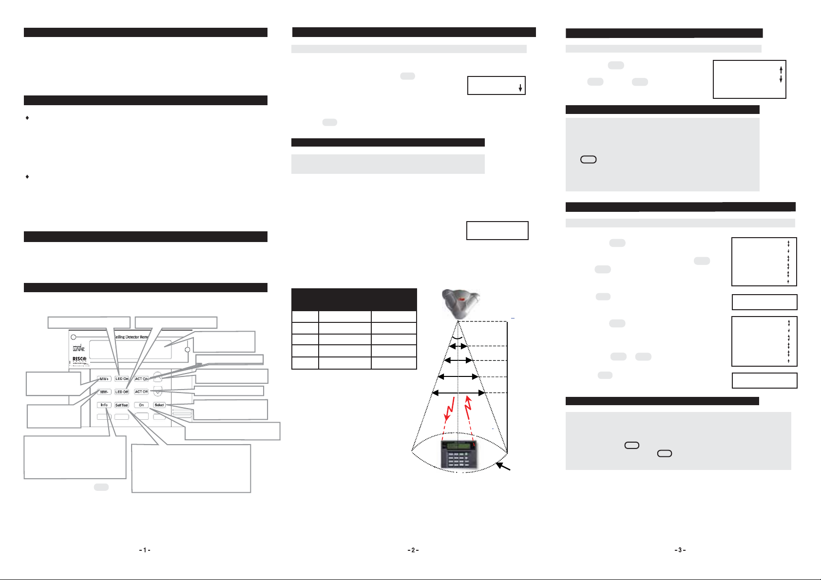
RC Key Functions
Each of the RC keys has a special functionality as explained below:
Enables the LEDs operation*
Increases MW
sensitivity (greater
range)*
Decreases MW
sensitivity (smaller
range)*
Gets info from the LuNAR as follows:
* MW sensitivity
* LEDs status operation
* ACT mode
* SW version
* Trouble indication
* Followed by pressing button
Select
Disables the LEDs operation*
LCD display: Visually
displays the data
information
Enables ACT mode*
Pressed to scroll up/down
a list
Disables ACT mode*
Accepts current selection
and transmits it to the
LuNAR.
Turns On/Off the Remote
Control device (toggled operation).
Activates LuNAR self-test.
The following info is displayed on the LCD:
* Input voltage level,
* MW signal and noise level,
* PIR CH1/CH2/CH3 DC signal level,
* PIR CH1/CH2/CH3 noise level
Starting to Use the RC
ACTION LCD DISPLAY
To use the RC, perform these steps:
1. Turn on the RC by pressing the button.
The following display appears each time the LuNAR
is activated:
2. If required, use the RC arrows to scroll down the list
and select your desired language.
3. Press
Select
to confirm your selection.
On
NOTE:
Upon power off, the last selected language is saved and will
be used upon next power up.
4. Point the RC infrared towards the LuNAR. Stand within
the 36° zone (see below) for optimum reception. The
effective RC reception distances and mounting heights
are shown below.
5. If the LuNAR does not respond, it is probably due to
a link failure; change RC position until the link is
achieved.
“No link” state message may appear if the LuNAR is
not enabled for RC communication (see “Enabling RC
Communication with the LuNAR” section).
A
B
C
D
E
Mounting
Height
2.7m - 4.9m
4.9m - 6.2m
6.2m - 7.8m
7.8m - 8.6m
8.6m
Diameter
1.6m
3m
3.7m
4.7m
5.2m
E
0
36
Point
REMOTE READY
ENGLISH
NO LINK, TRY TO
CHANGE POSITION
LuNAR
Height
D
C
B
A
Diameter
Getting Information
ACTION LCD DISPLAY
1. Press the button to get the desired
info; the info appears on the LCD. Use the
up or down arrows to scroll
up/down the list and view the desired info.
Info
>
>
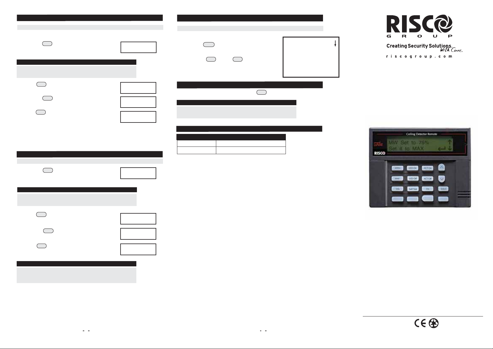
MW set to XXX
ACT is enabled/disabled
LED is enabled/disabled
Software Version XXX
No trouble/trouble
NOTES:
1. There are 3 optional trouble messages:
*MW trouble: Trouble in the MW channel.
*PIR trouble: Trouble in the PIR channel.
*PS trouble: Trouble in the detector input voltage
Info
2. If button was not pressed, an “Unknown
MW/ACT/LEDs” message will appear on the LCD while
trying to change the settings of these parameters.
(MW/ACT/LEDs).
Increasing/Decreasing MW Sensitivity
ACTION LCD DISPLAY
1. Press the button to increase the MW
MW+
sensitivity. Select the desired sensitivity by
scrolling up/down the list, using the up or
>
down arrows.
2. Press to confirm and transmit your selection.
Select
>
The following message appears:
Select
MW-
>
>
3. Press the button to decrease the MW
sensitivity.
Select the desired sensitivity by scrolling
up/down the list,
using the or down arrows.
4. Press to confirm and transmit your selection.
The following message appears:
MW set to XXX
Set it to TRM
Set it to MAX
Set it to 85%
Set it to 65%
Set it to 50%
Set it to 25%
Set it to MIN
Settings were
updated
MW set to XXX
Set it to TRM
Set it to MAX
Set it to 85%
Set it to 65%
Set it to 50%
Set it to 25%
Set it to MIN
Settings were
updated
NOTES:
1. Selecting the “SET TO TRM” option from the displayed list of options,
implicates that the MW sensitivity will be set to the level defined by the
trimmer on the PCB.
2. If after pressing button you receive the message ”No link try to
change position”, pressing button again will transmit once more
the last selected parameters.
Select
Select
Figure 1: RC Key Functions
 Loading...