

RIDGID JP0600 Owner's Manual

2:1(5·60$18$/
$VVHPEO\
2SHUDWLRQ
5HSDLU3DUWV
)RU<RXU6DIHW\
5HDGDOOLQVWUXFWLRQVFDUHIXOO\
48(67,21625&200(176"
&$//5,'*,'
ZZZULGJLGZRRGZRUNLQJFRP
Part No. SP6173 Printed in Taiwan
-3
-2,17(53/$1(5

2
Table of Contents
Safety Instructions For Jointer/Planer ..........................3
Safety Signal Words ..................................................3
Major Hazards ............................................................3
Before Using the Jointer/Planer .................................3
Safety Labels and Indicators on the Jointer/Planer ...4
When Installing Or Moving the Jointer/Planer ............4
Before Each Use ........................................................4
To Reduce the Risk of Injury From Jams, Slips Or
Thrown Pieces (Kickbacks Or Throwbacks) .............5
Plan Ahead To Protect Your Eyes, Hands, Face
and Ears ...................................................................5
Inspect Your Workpiece .............................................5
Whenever Jointer/Planer Is Running .........................6
Before Leaving the Jointer/Planer ..............................6
Glossary of Terms for Woodworking ............................6
Motor Specifications and Electrical Requirements .......7
Power Supply and Motor Specifications ....................7
General Electrical Connections ..................................7
110-120 Volt, 60 Hz. Tool Information .......................7
Changing Motor Voltage ............................................8
Motor Safety Protection .............................................9
Wire Sizes ..................................................................9
Unpacking and Checking Contents ............................10
Tools Needed .................. ...... ....... ...... ....... ...... ....... .. 1 0
Unpacking ....................... .........................................10
List of Loose Parts ...................................................10
Loose Parts ..............................................................11
Loose Parts (From Bag Assembly) ..........................12
Assembly .............. ......................................................13
Assemble The Cabinet .......... ....... ...... ....... ...... .........13
Install the Leveling Feet ...........................................13
Assembling Cabinet Top/Motor Mount Assembly ....14
Attaching Motor Pulley .............................................15
Assemble Motor To Cabinet Top .............................15
Assembling Cabinet Top to Cabinet ........................16
Assemble Bed to Stand ............................ ...... .........16
Mounting On-Off Switch ...........................................17
Attach Front of Cabinet and Dust Chute ..................17
Assemble Fence To Bed ....... ....... ...... ....... ...... ....... ..1 8
Install Cutter Head Guard ........................................18
Cutter Head Guard Functional Check ......................18
Adjusting Guard Spring ......... ...................................19
Attaching Pulley Guard ............................................19
Installing Rear Cutter Head Guard ..........................19
Adjusting the Leveling Feet ............ ...... ....... ...... ....... ..19
Getting to Know Your Jointer/Planer ................. ....... ..20
Alignments .................. ............. ............. ............. .........22
Cutter Knife Alignment/Adjustments ........................22
Cutter Knife Sharpening ..........................................23
Adjusting Table Extension ..................................... ..23
Outfeed Table Adjustment .......................................24
Adjusting Table Gibs ....... ...... ....... ...... ....... ............... 25
Fence Tilt (Bevel Stop) Alignment ...........................25
Safety Instructions for Basic Jointer/Planer
Operation ....................... .......................... ............... 26
Feeding the Workpiece (All Operations) ..................26
To Reduce the Risk of Injury From Jams, Slips Or
Thrown Pieces (Kickbacks Or Throwbacks) ...........26
Plan Ahead to Protect Your Eyes, Hands, Face
and Ears .................................................................27
Whenever Jointer/Plane r Is Runn ing .......................27
Basic Jointer/Planer Cutting Op erati ons ........... .........28
Depth of Cut Handwheel Operation .........................28
Stop Pin Operation ..................................................28
Feeding the Workpiece ............................................28
Planing ..................... ................................. ............... 29
Jointing ....................................................................29
Beveling/Chamfering ...............................................29
Rabbeting ................................................................30
Stop Pin Operation ..................................................30
Support Long Workpieces .......................................30
Using the Hold-Down/Push-Blocks ..........................30
Sliding Fence Operation ..........................................31
Fence Tilt Operation ................................................31
Maintenance and Lubrication .....................................32
Maintenance ............................................................32
Lubrication ...............................................................32
Wiring Diagram ...........................................................33
Troubleshooting Guide ...............................................34
General ....................................................................34
Motor ............................... ............. ............. ............. ..35
Repair Parts ...............................................................36

3
Safety Instructions For Jointer/Planer
Safety is a combination of comm on sen se, staying aler t an d knowing h ow your jointer/pl aner wor ks. Read this manual
to understand this tool.
Safety Signal Words
DANGER: means if the safety information is not followed
someone will be seriously injured or killed.
WARNING: means if the safety information is not followed
someone could be seriously injured or killed.
CAUTION: means if the safety informat ion is not followed
someone may be injured.
Major Hazards
All of the s afety information and cutt ing steps are cr itical
to the safe operation of the jointer/planer.
1. Workpiece kickback
Kickback is the uncontrolled grabbing and throwing of the
workpiece durin g jointing or planing. If kickback occurs,
the workpiece can hit you or a bystander hard enoug h to
cause broken bones, internal organ injury or death. To
reduce or prevent kickback, read and follow the safety
information in the Jointing and Planing sections of the
manual.
2. Kickback followed by blade contact
Your fingers or hand c an co ntac t th e blade following kickback if your hands are unprotected or too near the cut ter
blades. Your fingers can be cut off. To reduc e the risk o f
contacting the cutting blades, read and follow the safety
information in the Jointing and Planing sections of the
manual.
3. Wrong way feed
Wrong way feed is feeding the workpiece into the cutter
blades in the direction of blade rotation. The workpiece
can be grabbed by the blades an d pull your hands into
the blades before you can let go or pull back. Fingers can
be cut off. To reduce th e risk of wrong way feed, always
feed the workpiece against the direction of blade rotation.
Cutter blade rotation is shown on t he sliding fence guard
(behind the center of the fence).
4. Thrown workpiece, chips and cutter blade pieces
The jointer/planer can throw the workpiece, workpiece
chips, or pieces of loose or broken cutter blades. You can
be blinded. Wear safety goggles labelled “ANSI Z87.1”
(or
in Canada CSA Z94-3-M88)
on the package.
DANGER: Follow the steps listed below to reduce
or eliminate the risk of being injured when using
the jointer/planer. Failure to do so can result in a
life threatening injury or death.
1. Lock the fence lock knob and the sliding guard
knob.
2. Se t the depth of c ut to less than 1/8" for jointing
and less than 1/32" for planing.
3. Check the blade guard for proper position and
smooth operation.
4. Keep hands as far away from the cutters as possible when jointing or planing.
5. Use push blocks or push sticks whenever possible.
6. Complete the cut without stopping or backing up
the workpiece.
7. Read and follow the safety information and
safety instructions in the operator’s manual and
in the safety labels on the jointer/planer.
8. Know location and function of all controls before
using tool. See “Getting to know your Jointer/
Planer” section of this manual.
Before Using the Jointer/Planer
WARNING: To reduce the risk of mistakes that
could cause serious, permanent injury, do not plug
the jointer/planer in until the following steps have
been satisfactorily completed.
Know and Understand the Jointer/Planer
• Completely assemble and align jointer/planer.
• Learn the use and function of the ON-OFF switch,
fence slide locking handle, cutter gua rd, depth of cut
hand wheel, locks and stops, fence bevel lock handle,
outfeed table, infeed table and hold-down/push-blocks.
• Review and understand all safety instructions and
operating procedures in this manual.
• Review the maintenance methods for this jointer/
planer.
• Fin d and read the warning label found on the jointer/
planer (shown below).

4
Safety Instructions For Jointer/Planer (continued)
Safety Labels and Indicators on the Jointer/Planer
The following labels and indicators are on your jointer/
planer. Locate, read and follow the safety instructions
and information contained in these labels.
1. Safety instruction label on the top of the guard.
2. Cutter rotation indicator is on top of the sliding guard.
3. Cutter position indicator is on top of the fence.
Push blocks and push sticks
Two plastic push blocks are supplied with your jointer/
planer. Use them when practical. The ru bber sole of the
push blocks give better traction with the wood than your
hands do. If they become slipper y, they can be cleaned
with rubbing alcohol, paint thinner or sandpaper.
CAUTION: Use rubbing alcohol or paint thinner
only as described on their containers. Use only in
well ventilated areas away from open flames,
sparks or heat sources.
Push blocks can’t always be used. With larger workpieces, you may have better control fo the workpiece
using your hands. Always make a test pass first to determine which method gives you better control.
Before you make any cut, plan your hand positions. If a
kickback should occur, plan so that your hands will not fall
or be forced into the cutters.
Three Inch Rule (3")
Generally, if your hands are closer than th ree inches to
the blade as you feed the wood, use push blocks. This
gives extra protection to your h ands by placing the push
blocks between your hands and the cutters.
Always Use Push Blocks When Planing, Beveling Or
Chamfering
When jointing, test for workpiece stability before actually
jointing, and use push blocks when you can without sacrificing control.
When Installing Or Moving the Jointer/Planer
Reduce the Risk of Dangerous Environment.
• Use th e jointer/planer in a dry, indoor place protected
from rain.
• Keep work area well lighted.
To reduce the risk of injury from unexpected jointer/
planer movement.
• Bolt or clamp the jointer/planer to firm level surface
where there is plenty of room for moving the workpiece
through the entire cut.
• Suppo rt the jointer/planer s o the tables are level and
the jointer/planer does not rock.
• Put the jointer/planer where neither operators nor
bystanders must stand in line with the wood while planing or jointing it.
• To reduce the risk of injury from elect rical shock, make
sure your fingers do not touch th e plug’s metal prongs
when plugging in or unplugging the jointer/planer.
• Turn off and unplug the jointer/pla ner before moving it
to a new area. To reduce the risk of back injury, get
help when you need to lift or move the jointer/planer.
• Bolt the jointer/planer to the floor if it tends to slip, walk,
slide or tip over. Be especially aware of movement
when jointing/planing long heavy boards.
• Never Stand On Tool. Serious injury could occur if the
tool tips or you accidentall y hit the cut ter head. Do not
store anything above or near the tool where anyone
might stand on the tool to reach them.
Before Each Use
Inspect your jointer/planer.
WARNING: The 2-1/2
inch jointer/planer pulley and
the 3-1/2 inch motor pulley furnished will run the
cutter head at about 5000 RPM when used with a
3450 RPM motor. Use of different types of pulleys
or motors will change this speed and could cause
jamming, binding, kickback, thrown knives or
other dangers.
• To reduce the risk of injury from accidental starting, turn
the switch off, unplug the jointer/planer, and remove the
switch key before moving the cutter head guard, changing the blades, changing the setup, or adjusting anything.
• Check fo r alignment of moving parts, binding of moving
parts, breakage of parts, unit stability, and any other conditions that ma y aff ect th e way the jointer/planer works.
• Don’t force the tool. It will do the job better and safer at
the rate for which is was designed.
• If any part is missing, b en t or br oken in any wa y, or any
electrical par t does not wor k properly, turn the jointer/
planer off and unplug the jointer/planer.
• Replace damaged, missing or failed parts before using
the jointer/planer again.
• Make sure the cutter guard works properly. With the
switch off and key removed, pull the cutter g uard open
and let go. If the guard doesn ’t smoothly swing closed,
contact an Authorized Service Center.
• Ma ke sure the cutter head turn s in the right direction .
The top should move toward the infeed table. If the cutter head turns the wrong direction, contact an Authorized Service Center.
• Keep Jointer/Planer interior free of wood chips and
dust buildup around motor and switch box.
• Keep knives sharp. Dull or nicked knives tend to
“pound” and chew at the wood, causing kickbacks.
• To reduce the risk of injury from unsafe accessories,
use only recommended accessories.

5
To Reduce the Risk of Injury From Jams, Slips Or Thrown Pieces (Kickbac ks Or Throwbacks)
• Use this jointer/planer to cut only wood.
• Use push blocks or push sticks whenever possible.
• Plan your hand placement so your fingers wi ll not be
anywhere a sudden slip could cause th em to slide or
fall into the cutter head. When using only one holddown/push-block to feed the wood, do not put your
other hand on the jointer/planer, workpiece, or holddown/push-block.
• To reduce the risk of injury from thrown pieces, make
sure the knives are sharp, properly installed and the
cutter knives wedge screws are tight.
• Make sure th e clamps a nd locks are tight a nd there is
not excessive play in any parts.
• Adjus t t he d epth of c ut to be tween 1 / 32 a nd 1 /16 of a n
inch for best results in most operations. A deep cut
makes feeding the wood harder and can cause the
wood to kickback. To be sure you will make a depth of
cut you planned, always lower the infeed table slightly
farther than you wanted then, raise the table to the
desired depth.
• Use The Right Tool. Don’ t force tool or attachment to
do a job it was not designed for.
Inspect your work area.
• Keep work area clean.
• Cluttered areas and benches invite accidents.
• Floor must not be slippery from wax or sawdust.
• To reduce the risk of burns or other fire damage, never
use the jointer/planer near flammable liquids, vapors or
gases.
• Before using the jointer/planer, clear the table of all
objects not needed to feed the workpiece.
• To reduce the risk of injury , don’t do any layout, assembly, or setup work on the jointer/planer bed.
• Ma intain tools with care. Keep tools sharp an d clean
for best and safest performance. Follow instructions for
lubricating and changing accessories.
Plan Ahead To Protect Your Eyes, Hands, Face and Ears
Reduce the Risk of Accidental Starting.
• Make sure switch is “OFF” before plugging jointer/
planer into a power outlet.
Dress for safety.
• Any power tool can throw foreign objects into the eyes.
This can result in permanent eye damage. Always
wear safety goggles, not glasses complyi ng with ANS I
Z87.1 (or in Canada CSA Z94-3-M88) shown on package. Everyday eyeglasses have only impact resist ant
lenses. They are not safety glasses. Safety goggles
are available at many local retail stores. Glasses or
goggles not in compliance with ANSI or CSA could
seriously hurt you when they break.
• For dusty operations, wear a dust mask along with
safety goggles.
• Do not wear lo ose clothi ng, gloves, neckties or jewelry
(rings, wrist watches). They can get caught and draw
you into moving parts.
• Wear nonslip footwear.
• Tie back long hair.
• Roll long sleeves above the elbow.
• Noi se levels vary widely. To reduce the ri sk of poss ible
hearing damage, wear ea r plugs or muffs when us ing
jointer/planer for hours at a time.
Inspect Your Workpiece
• Make sur e there are no nails or foreign objects in the
part of the workpiece to be cut.
Plan your cut.
• Small or thin workpieces can kickback when they tip
over on the tables or into the cutter head. To reduce
the risk of cutter head contact or workpiece kickback:
- Never joint, plane or bevel workpieces shorter than
12 inches.
• When jointing or rabbeting:
- Never joint or bevel workpieces less than 3/4 inch
wide or 1/4 inch thick.
- Always use the hold-down/push-blocks when jointing
or beveling wood whenever possible.
- When rabbeting, always make cuts in 1/8" incre-
ments or less.
• When planing or beveling:
- Never plane wood thinner than 1/2 inch.
- Always use hold-down/p ush-blo cks whe n planing w ood.
-Never cut Freehand. Guide your workpiece solidly
against the fence and table top.
- Make sure the re’s no debris be tween the workpiece
and its supports.
Use extra caution with large, very small or awkward
workpieces.
• Use extra suppor ts (tables, s aw horse s, blocks, etc.) for
any workpiece large eno ugh to ti p when n ot held d own
to the table top. Never use another pers on as additional
support or to help fe e d, s uppo rt or pull th e wo rkp iec e .

6
Safety Instructions For Jointer/Planer (continued)
• Never cut more than one workpiece at a time.
• Never turn your jointer/planer “ON” before clearing
everything except the workpiece and related support
devices off the table.
• Before trying a new or little used operation, carefully
plan your hand placement. Make sure you have proper
hold-down/push-blocks, jigs, fixture s, stops, etc. ready
to use.
Whenever Jointer/Planer Is Running
WARNING: Don’t allow familiarity (gained from frequent use of your jointer/planer) cause a careless
mistake. Always remember that a carele ss f r action
of a second is enough to cause a severe injury.
• Before actually cutting with the joi nter/planer, let it run
for a while. If it makes an unfamiliar noise or vi brates a
lot, stop immediately. Turn the jointer/planer off.
Unplug the jointer/planer. Do not restart until finding
and correcting the problem.
Keep Children Away.
• Keep all visitors a safe distance from the jointer/planer.
• Make sure bystanders are clear of the jointer/planer
and workpiece.
Don’t Force Tool.
• Let the cutter head reach full speed before cutting.
• Feed the workpiece into the jointer/planer only fast
enough to let the tool cut without bogging down or
binding.
Before freeing jammed material.
• Turn switch “OFF”.
• Wait for all moving parts to stop.
• Unplug the jointer/planer.
• Che ck knives for sharpn ess and nicks before starting
again.
Before Leaving the Jointer/Planer
• Turn the jointer/planer off.
• Wait for knives to come to a complete stop.
• Unplug the jointer/planer.
• Make workshop child-proof. Lock the shop. Disconnect
master switches. Remove the yellow switch key. Stor e
it away from children and others not qualified to use
the tool.
Glossary of Terms for Woodworking
Bed
The combination of infeed and outfeed table surfaces
which support the workpiece during a cutting operation.
Bevel/Chamfer
Removing wood along the edge of a board to make that
edge straight, smooth and angled to the board face which
is against the fence.
Cutter Guard
Spring loaded guard or shield covering the cutter head.
Cutter Head
The cutter head is a rotating piece with three adjustable
knives. The cutter head removes material fr om the workpiece
Depth of cut
A term used to i ndicate how deep i nto the wor kpiece th e
cutter knives will cut.
Fence
The fence is attached to the jointer/planer base. The
fence helps support and guide the workpiece as it is
pushed across the cutter head.
Freehand
Using the tool without holding the workpiece firmly
against the fence and
table. This can let the workpiece
twist and kick back and must never be attempted.
Gum
A sticky, sap based residue from wood products.
Hold-Down/Push-Blocks
They are required for your own safety. Th ey are used to
hold your workpieces agains t the table and
fence when
planing, rabbeting or jointing.
Infeed Table
The section of the jointe r bed upon which the workpiece
is placed before being pushed into the cutter head. Infeed
table height is adjustable which allows the operator to
select the depth of cut.
Jointing
The removal of wood along the ed ge of a b oard so as to
make that edge straight, smooth and squar e to the bo ard
face which is against the fence.
Kickback
An uncontrolled grabbing and thr owing of the workpiece
back toward the operator by the rotating cutter head.
Leading End
The end of the workpiece which is pushed into the cutter
head first.
Outfeed Table
The section of a jointer bed which supports the workpiece after it passes over the cutter head.
Planing
Removing wood from the widest surface or face of a
board so as to make it flat and smooth.
7
Rabbet
A notch cut into the edge of workpiece.
Resin
A sticky, sap based substance that has hardened.
Revolutions Per Minute (RPM)
The number of turns co mpleted by a spinning object in
one minute.
Throw-Back
Throwing of pieces in a manner similar to a kickback.
Trailing End
The workpiece end last cut by the knives.
Workpiece
The item on which the cutting operation is being performed. The surfaces of a workpiece are commonly
referred to as faces, ends and edges.
Motor Specifications and Electrical Requirements
Power Supply and Motor Specifications
WARNING: To reduce the risk of electrical hazards,
fire hazards or damage to the tool, use proper circuit protection. Your tool is wired at the factory for
operation using the voltage shown. Connect tool
to a power line with the appropriate voltage and a
15-amp branch circuit. Use a 15-amp time delay
type fuse or circuit breaker. To reduce the risk of
shock or fire, if power cord is worn or cut, or damaged in any way, have it replaced immediately.
The A/C motor used on this tool is a capacitor start, nonrev ersib le t ype , wired at the f actory f or 110- 120V AC, 60 Hz.
operation.
Follow the instructions on page 8 to connect the motor for
220-240V A/C operatio n.
General Electrical Connections
DANGER: To reduce the risk of electrocution:
1. Use only identical replacement parts wh en servicing. Servicing should be performed by a
qualified service technician.
2. Do not use in rain or where floor is wet.
This tool is intended for indoor residential use
only.
WARNING: Do not permit fingers to touch the terminals of plug when installing or removing the
plug to or from the outlet.
If power cord is worn or cut, or damaged in any way, have
it replaced immediately.
110-120 Volt, 60 Hz. Tool Information
The plug supplied on your tool may not fit into the outlet
you are planning to use. Your loc al electrical code may
require slightly different power cord pl ug connections. If
these differences exist refer to and make the proper
adjustments per your local code before your tool is
plugged in and turned on.
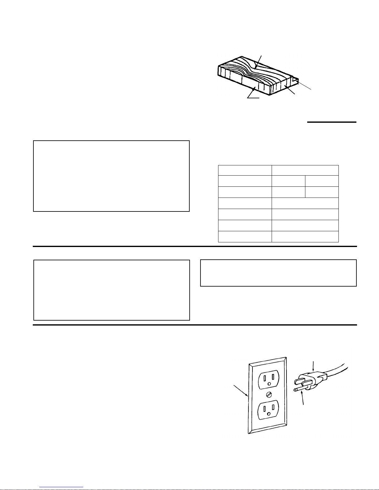
In the event of a malfunction or breakdown, grounding
provides a path of le ast resistance for electric curren t to
reduce the risk of electric shock. This tool is equipped
with an electric cord having an equipment grounding conductor and a grounding plug, as shown. The plug must be
plugged into a mat ching outlet that is properly installed
and grounded in accordance with all local codes and
ordinances.
Face
Edge
End
Rabbet
Rated Horsepower 3/4
Voltage
110-120 220-240
Amperes
12 6
Hertz (Cycles)
60
Phase
Single
RPM
3450
Rotation of Shaft
Counterclockwise
Properly
Grounded
Outlet
3-Prong Plug
Grounding
Prong
8
Motor Specifications and Electrical Requirements (continued)
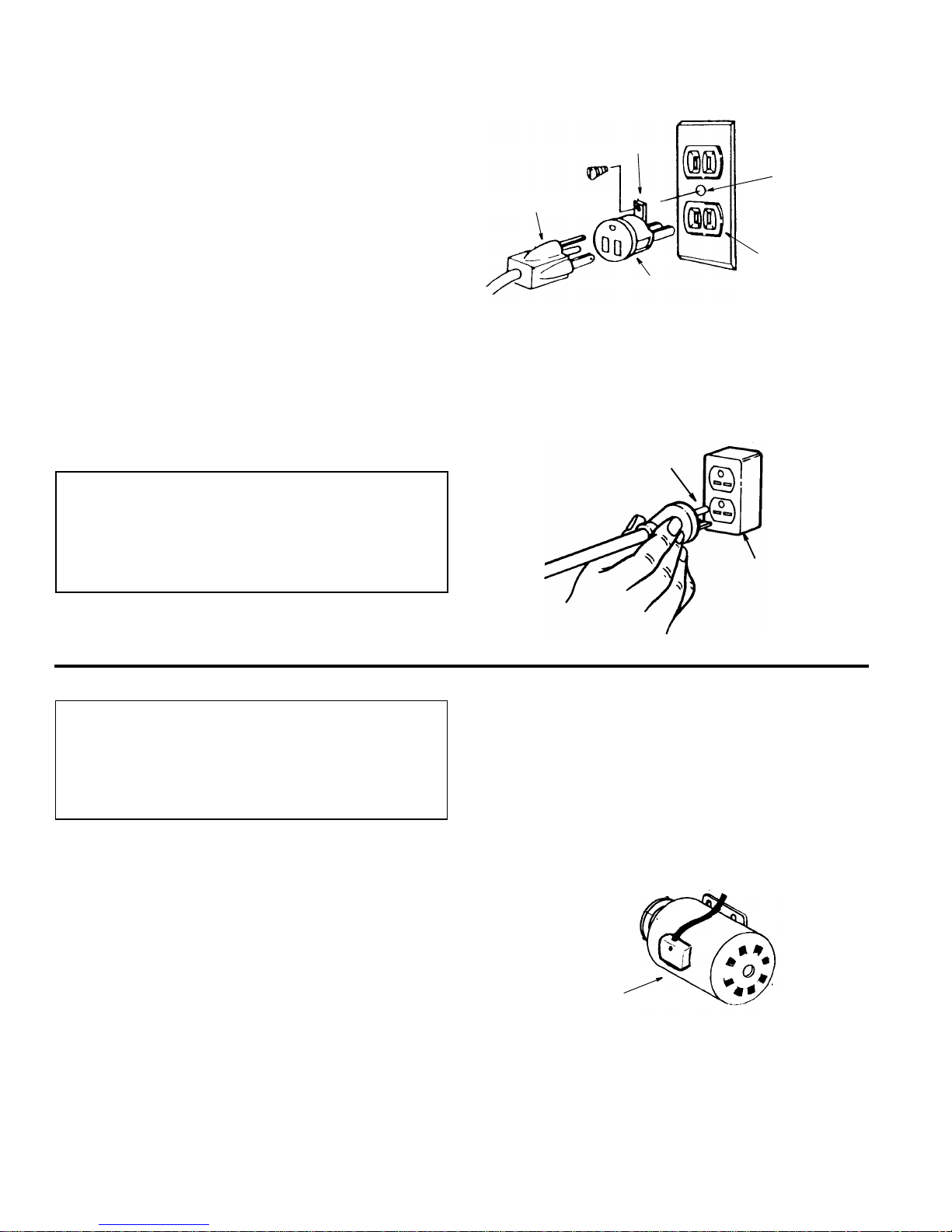
Do not modify the plug pr ovide d. I f it wi ll not fit the ou tle t ,
have the proper outlet installed by a qualified electrician.
A temporary ada pte r may be used to co nne ct t his pl ug t o
a 2-pole outlet, as shown. This temporary adapter should
be used only until a properly grounded outlet can be
installed by a qualified electrician. The green colored
rigid ear, lug and the like, extension from the adapter
must be connected to a permanent ground such as a
properly grounded outlet box.
Improper connection of the equipment grounding conductor can result in a r isk of electric s hock. The conductor with insulation having an outer surface that is green
with or without yellow stripes is the equ ipment groundin g
conductor. If repair or replacem ent of the electr ic cord or
plug is necessary, do not connect the eq uip men t- groun ding conductor to a live terminal.
If the grounding instructions are not completely understood, or if you are in doubt as to whether the tool is properly grounded check with a qualified electrician or service
personnel.
WARNING: If not properly grounded, this tool can
cause an electrical shock, particularly when used
in damp locations, in proximity to plumbing, or out
of doors. If an electrical shock occurs there is the
potential of a secondary hazard, such as your
hands contacting the knives.
110-120 Volt, 60 Hz. Tool Connections
NOTE: The adapter illustrated is for use only if you already
have a properly grounded 2-prong outlet.
NOTE: In Canada the use of a temporar y adapter is not
permitted by the Canadian electrical code.
220-240 Volt, 60 Hz. Tool Connections
Changing Motor Voltage
WARNING: If not properly grounded, this tool can
cause an electrical shock, particularly when used
in damp locations, in proximity to plumbing, or out
of doors. If an electrical shock occurs there is the
potential of a secondary hazard, such as your
hands contacting the knives.
NOTE: The jointer is prewired at the factory for 120V
operation. Use the following procedure to chang e motor
voltage. To change to 240V application an additional wire
nut is supplied from the factory. This part is included in
the loose parts.
1. Open the motor junction box cover located on the side
of the motor.
2. Cut off the 120 volt power cord plug and replace it with
a (3 blade) 240 volt 15 amp U.L. lis ted plu g. ( S ee illus tration of 240V plug & receptacle.) Conn ect the power
cord white and black leads, respectively, to the “hot”
plug blade terminals and connect the power cord
green grounding wire to the plug ground pr ong terminal.
3. Remove and discard the electrical tape from the wire
nuts. Remove wire nuts.
4. Reconnect the leads as shown in the “Wiring Diagram”
section at the rear of manual.
5. Reinstall the wire nuts and wrap with two layers of new
U.L. listed electrical tape per wire nut.
6. Recheck your wiring to the wiring diagrams. Do this so
you can be sure that the wiring is correct.
7. Reinstall the junction box cover.
3-Prong
Adapter
2-Prong
Outlet
Make Sure This
Is Connected
Ground
Plug
Green
to a Known
Grounding Lug
Grounding
Prong
Grounded
Outlet Box
Junction
Box Cover

9
Motor Safety Protection
IMPORTANT: To reduce the risk of motor damag e, this
motor should be blown out or vacuumed frequently to
keep sawdust from interfering with nor mal moto r ventilation.
1. Connect this tool to a power source with the appr opriate voltage for your model and a 15-amp branch circuit
with a 15-amp time del ay fuse or c i rcui t brea ker. Using
the wrong size fuse can damage the motor.
2. If the motor won’t start, turn off the power switch immediately and unplug the tool. Check the cutter h ead to
make sure it turns freely . If the cutter head is free, try to
start the motor again. If the motor still does not start,
refer to the "Motor Troubleshooting Chart."
3. Fuses may "blow" or circuit breakers may trip frequently if:
a. Motor Is Overloaded-Overloading can occur if you
feed too rapidly or make too many star t/stops in a
short time.
b. Line voltages should not be more than 10% above
or below the nameplate voltage. For heavy loads,
however, the voltage at motor term inals must equal
the voltage specified for your model.
c. Improper or dull jointer knives are used.
4. Most motor tro ubles may be traced to loose or in correct connections, overload, l ow voltage (such as small
size wire in the suppl y circuit) or to overly long supply
circuit wire. Always check the connections, the load
and the supply circuit whenever motor doesn’t work
well. Check wire sizes and length with the Wire Size
Chart.
Wire Sizes
NOTE: Make sure the proper extension cord is us ed an d
is in good condition.
The use of any extension cord will cause some loss of
power. To keep this to a minimum and to prevent overheating and motor burn-out, use the table shown to
determine the minimum wire size (A.W.G.) extension
cord.
Use only 3-wire extension cords which have 3-prong
grounding type plugs and 3-pole receptacles which
accept the tools plug.
Extension
Cord Length
Gauge (A.W.G.)
110-120V 220-240V
0-25 Ft.
26-50 Ft.
14
12
16
14

10
Unpacking and Checking Contents
Tools Needed
Unpacking
WARNING: To reduce the risk of injury from unexpected starting or electrical shock, do not plug the
power cord into a power source outlet during
unpacking, until all assembly steps are complete,
and you have read and understand the safety and
operating instructions.
WARNING: This tool is heavy. To reduce the risk of
back injury, g et help whenever you have to lift the
tool.
Your jointer/planer is shipped complete in one carton and
includes a steel cabinet.
1. Clear yourself a large work area. Remove the jointer/
planer and par ts from the carton. Lift the tool at the
bottom of the base.
2. Place the tool on a secure, stationary work surface and
look it over carefully.
3. Separate all par ts from packing materials and check
each one with the “Table of Loose Parts ” and the “Lis t
of Loose Parts” to make certain all items are
accounted for before discarding any packing material.
If you are missing any parts, check packing material for
those items.
WARNING: If any parts are missing, do not attempt
to assemble the jointer/planer. Do not plug in the
power cord or turn the switch on until the missing
parts are obtained and are installed correctly.
4. Contact an Authorized Ser vice Cent er to get the missing par ts. Use the “Repair Parts” pages at the end of
this manual to identify the par t number of the missin g
parts after completing the “Unpacking and Checking
Contents section.
CAUTION: The cutting knives are extremely sharp.
Do not touch the cutter knives.
5. The top of the table and the front of the fence are
coated with a protective substance before shipping.
These surfaces must be cleaned an d protected b efore
using the jointer/planer. Clean these surfaces with a
general purpose solvent, such as mineral spirits. Water
will rust the surfaces. Do Not use water, soapy water or
water based cleaners.
CAUTION: Use solvents according to the instructions on their package. Use only in well ventilated
areas, away from flames, sparks or heat sources.
Do not use solvents in closed areas.
6. Protect the exposed surfaces with wax. Paste wax or
automotive wax are both good for this job. The wax will
protect the surface from rust and wi ll make it easier to
slide the wood along the table and fence. Automotive
wax is best as it will not rub off on the wood.
7. Wipe all parts thoroughly with a clean, dry cloth.
List of Loose Parts
NOTE: Before beginning assembly, check that all parts
are included. If you are missing any part, do not asse mble the tool. Call 1-800-4-RIDGID or E-mail us at
info.@ridgidwoodworking.com to get the missing part.
Sometimes small parts can get lost in packaging material. Do not throw away any packaging until jointer/
planer is put together. Check packaging for missing
parts before contacting RIDGID. A complete parts list
(Repair Parts) is at the end of the manual. Use the list
to identify the number of the missing part.
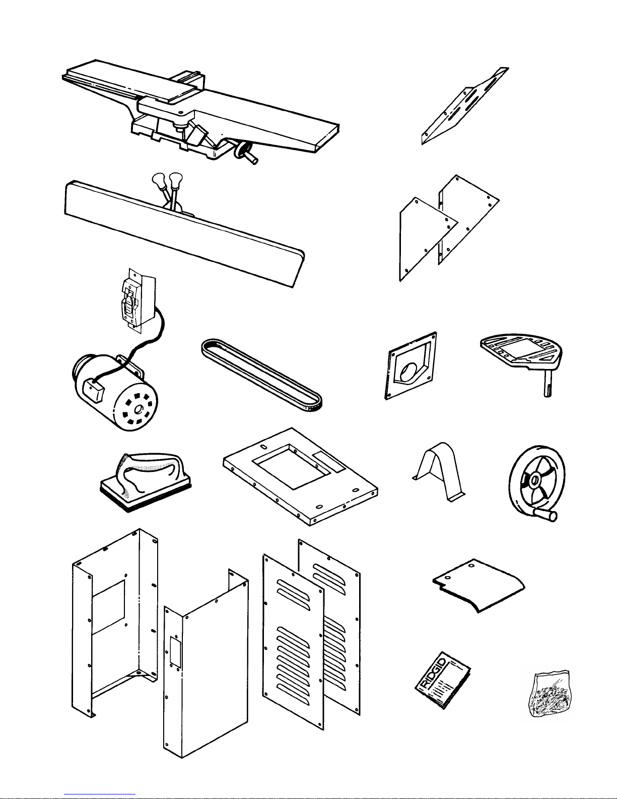
The following parts are included:
Item Part Name Qty.
A Jointer Bed Assembly..................................... 1
B Fence Assembly............................................. 1
C Motor Assembly w/Switch............................... 1
D V-Belt..............................................................1
E Push Blocks.................................................... 2
F Top Panel............................ ...... ....... ...... ....... .. 1
G Left Side Panel............................................... 1
H Right Side Panel............................................. 1
J Front Panel..................................................... 1
K Rear Panel....................................... ...... ....... .. 1
L Motor Mount Plate.......................................... 1
M Motor Mount Sides......................................... 2
N Sawdust Chute............................................... 1
P Cutter Guard................................................... 1
Q Pulley Guard................................................... 1
R Handwheel ..................................................... 1
S Cover.............................................................. 1
T Owners Manual .............................................. 1
U Bag Loose Parts..............................................*
* Quantity of bag may vary, bags may contain
smaller bags.
2 Ft. Straight Edge
Phillips Screwdriver
Combination
Square
(12"Blade)
Select the straight edge of a board.
Draw light line on
board along edge
This edge must be perfectly straight.
Should be no gap or overlap here when
square is flipped over in dotted position
Adjustable Wrench
Combination square must be true. Check its
accuracy as shown
11
Loose Parts
E
D
A
B
M
N
T
L
R
S
U
G
H
J
K
C
F
Q
P
12
Unpacking and Checking Contents (continued)
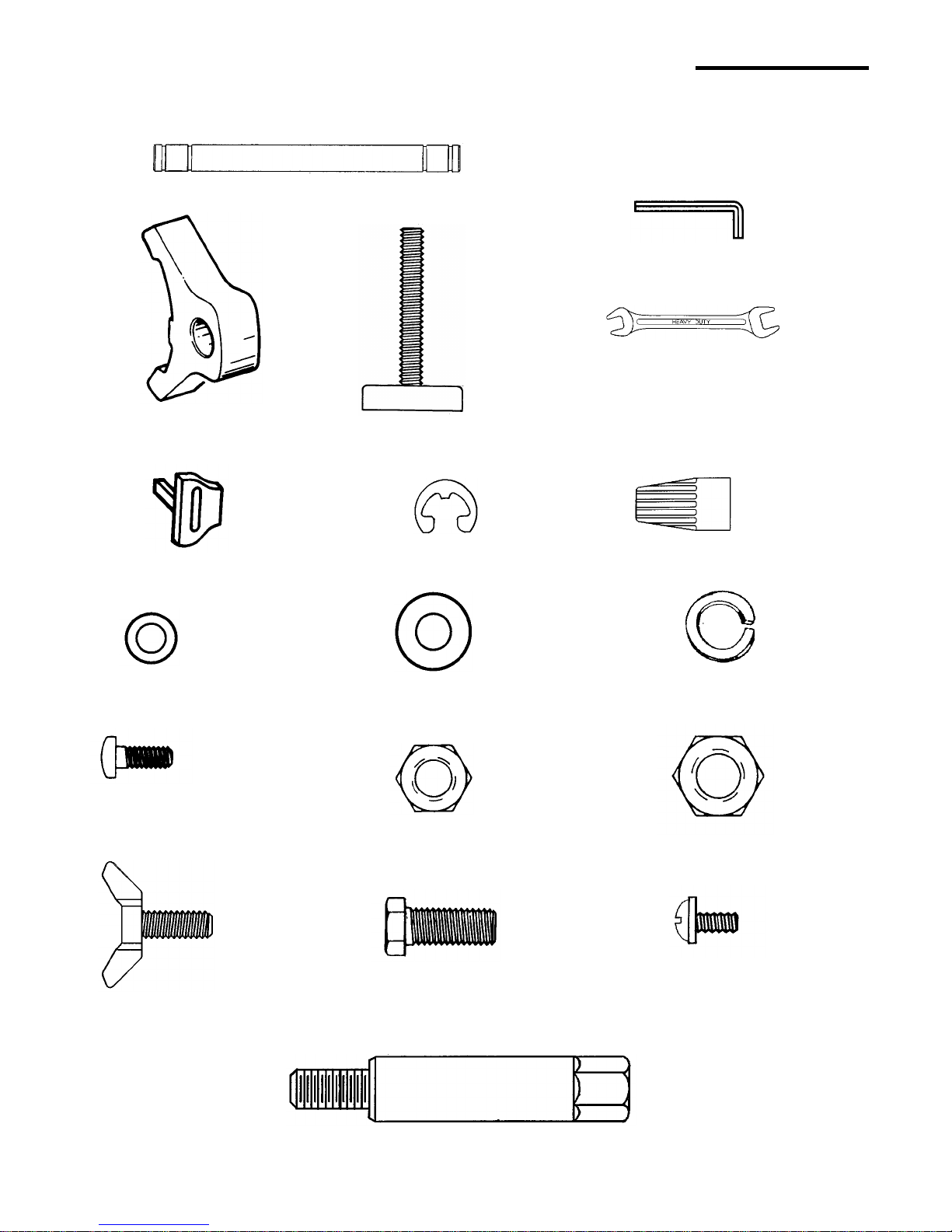
Loose Parts (From Bag Assembly)
Hex Bolt (4)
Leveling Feet (4)
Washer (3)
Switch Key (1)
Hex Jam Nut (4)
3mm Hex-L Wrench (1)
Rod-Knife Gauge (1)
Gauge-Knife (2)
Retaining Ring (4)
1/4"
Lockwasher (3)
3/8"
Nut Hex (4)
5/16-18
5/16-18 x 3/4"
Screw Pan Head (3)
1/4-20 x 1/2
Wrench 8mm/10mm (1)
Wrench 12mm/14mm (1)
3/8-16
Wire Nut
Washer (8)
5/16"
Screw Pan Head Cr Serr (44)
(Machine Screw w/Washer Head
3/16-24 x 3/8
Jointer Mounting Stud (3)
Screw Wing
1/4-20 x 5/8 (4)
13
Assembly
WARNING: This tool is heavy. To reduce the risk of
back injury, g et help whenever you have to lift the
tool.
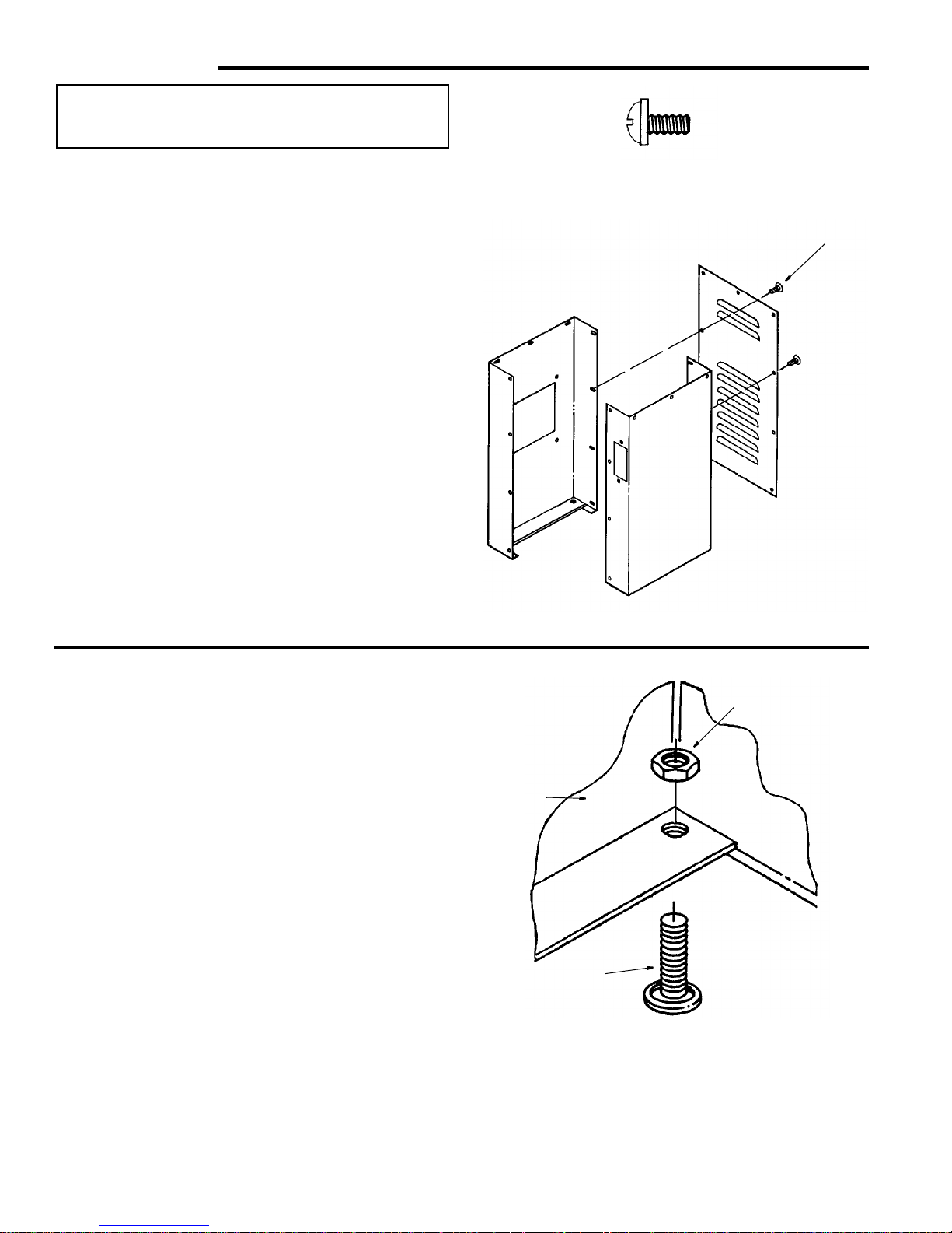
Assemble The Cabinet
1. From among the loose parts, find the following:
6 Machine Screws w/Washer Head
1 Cabinet Rear
1 Left Cabinet Side
1 Right Cabinet Side w/Switch Opening
2. Assemble the three sides of the cabinet as shown,
using the three lowest holes on each side of the cab inet rear.
NOTE: The front of the cabinet will be attached later.
Install the Leveling Feet
From the loose parts bag find the following:
4 Leveling Feet
4 Nut Hex 3/8-16
Install leveling feet as shown. Later when the jointer/
planer is completely assembled and put in its per ma nent
location in your wor k sh op, you will n eed to level the cab inet.
Cabinet Rear
Left Cabinet
Side
Right Cabinet Side
w/Switch Opening
Washer
Head Screw
Machine Screw w/Washer Head
3/16-24 x 3/8
Leveling Foot
3/8-16 Hex Nut
Cabinet
˜
B
o
t
t
o
m
14
Assembly (c ontinued)
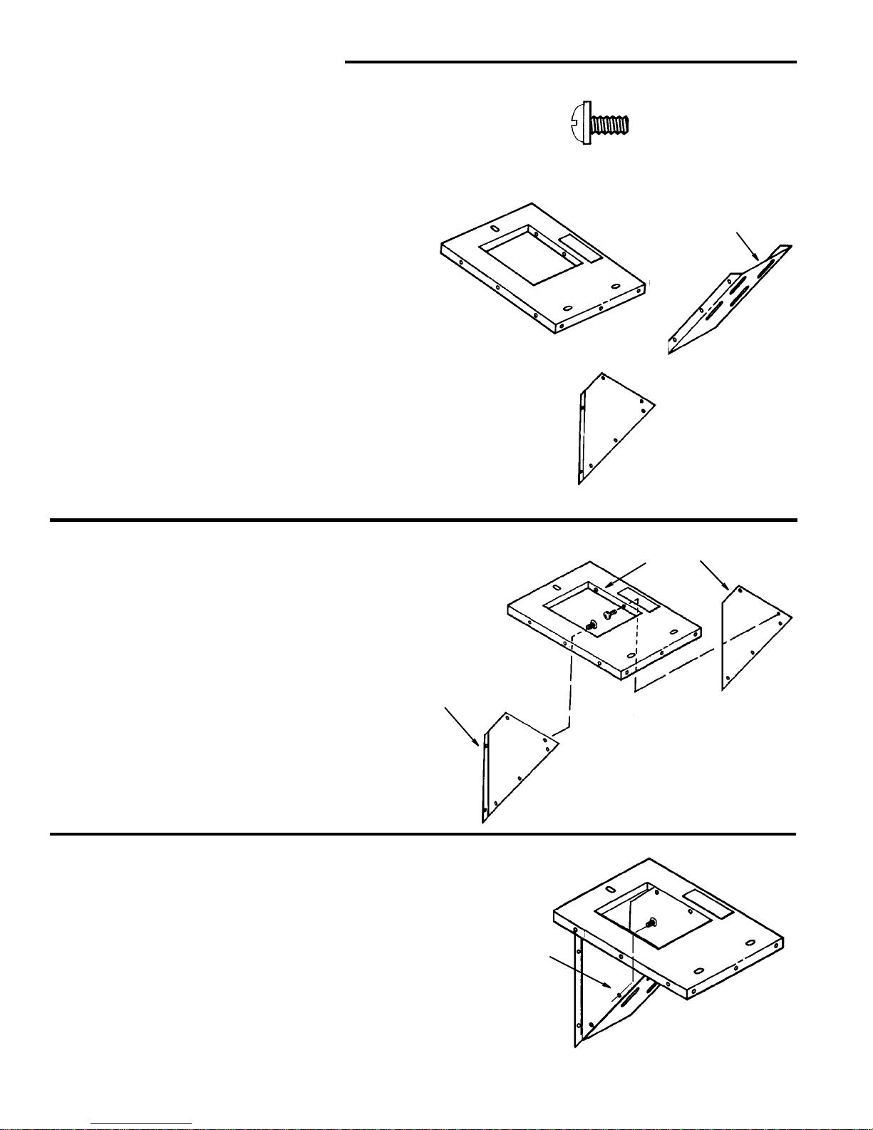
Assembling Cabinet T op/Motor Mount Assemb ly
1. From among the loose parts, find the following:
10 Machine Screw w/Washer Head
1Cabinet Top
1 Motor Mount Plate
2 Motor Mount Side
2. Attach the motor mount sides to the cabinet top as
shown.
3. Attach the motor mount plate to the motor mount sides
and cabinet top.
Cabinet Top
Motor Mount
Plate
Motor Mount
Side
Machine Screw w/Washer Head
3/16-24 x 3/8
“TOP”
Flange to
outside
Motor Mount Side is
Inside Cabinet Top
Motor Mount
Side on Outside
of Mount Plate
~
 Loading...