

RIDGID jobmax R8223407 Operator Maintenance

OPERATOR’S MANUAL
MANUAL DEL OPERADOR
JobMax™ JIG SAW HEAD
TÊTE À SCIE SAUTEUSE JobMax
Use only with base model Series A, B, D, E
• Series A includes models R8223400, R8223500
• Series B includes model R2850, R2851
• Series D includes model P246
• Series E includes model R8620
Compatible uniquement avec le base modèle de série
A, B, D, E
• Série A inclut modèle R8223400, R8223500
• Série B inclut modèle R2850, R2851
• Série D inclut modèle P246
• Série E inclut modèle R8620
Utilizar sólo con el Modelo base número serie A, B, D, E
• Serie A incluye modelos R8223400, R8223500
• Serie B incluye modelos R2850, R2851
• Serie D incluye modelos P246
• Serie E incluye modelos R8620
MANUEL D’UTILISATION
™
CABEZAL DE SIERRA
DE VAIVÉN JobMax™
R8223407
To register your RIDGID
product, please visit:
http://register.RIDGID.com
Pour enregistrer votre
produit de RIDGID,
s’il vous plaît la visite:
http://register.RIDGID.com
Para registrar su producto
de RIDGID, por favor visita:
http://register.RIDGID.com
Your JobMax™ accessory has been engineered and manufactured to our high standards for dependability, ease of operation,
and operator safety. When properly cared for, it will give you years of rugged, trouble-free performance.
WARNING:
To reduce the risk of injury, the user must read and understand the operator’s manual before using this product.
Thank you for your purchase.
SAVE THIS MANUAL FOR FUTURE REFERENCE
Cette JobMax™ accessoire a été conçue et fabriquée conformément
à nos strictes normes de fiabilité, de simplicité d’emploi et de
sécurité d’utilisation. Correctement entretenue, elle vous donnera
des années de fonctionnement robuste et sans problème.
AVERTISSEMENT :
Pour réduire les risques de blessures, l’utilisateur doit
lire et veiller à bien comprendre le manuel d’utilisation
avant d’employer ce produit.
Merci de votre achat.
CONSERVER CE MANUEL POUR
FUTURE RÉFÉRENCE
Su JobMax™ accesorio para la obra ha sido diseñado y fabricado
de conformidad con nuestras estrictas normas para brindar
fiabilidad, facilidad de uso y seguridad para el operador. Con el
debido cuidado, le brindará muchos años de sólido y eficiente
funcionamiento.
ADVERTENCIA:
Para reducir el riesgo de lesiones, el usuario debe leer
y comprender el manual del operador antes de usar
este producto.
Le agradecemos su compra.
GUARDE ESTE MANUAL PARA
FUTURAS CONSULTAS

TABLE OF CONTENTS
TABLE DES MATIÈRES / ÍNDICE DE CONTENIDO
Introduction ......................................................................................................................................................................2
Introduction / Introducción
Specific Safety Rules ........................................................................................................................................................ 3
Règles de sécurité particulières / Reglas de seguridad específicas
Symbols ............................................................................................................................................................................ 4
Symboles / Símbolos
Features ............................................................................................................................................................................5
Caractéristiques / Características
Assembly .......................................................................................................................................................................... 6
Assemblage / Armado
Operation .......................................................................................................................................................................6-8
Utilisation / Funcionamiento
Maintenance ..................................................................................................................................................................... 8
Entretien / Mantenimiento
Warranty ...........................................................................................................................................................................9
Garantie / Garantía
Figure numbers (illustrations) ....................................................................................................................................10-11
Figure numéros (illustrations) / Figura numeras (ilustraciones)
Parts Ordering and Service ...............................................................................................................................Back Page
Commande de pièces et réparation / Pedidos de piezas y servicio ......................................................... Page arrière / Pág. posterior
INTRODUCTION
INTRODUCTION / INTRODUCCIÓN
This product has many features for making its use more pleasant and enjoyable. Safety, performance, and dependability
have been given top priority in the design of this product making it easy to maintain and operate.
* * *
Ce produit offre de nombreuses fonctions destinées à rendre son utilisation plus plaisante et satisfaisante. Lors de la
conception de ce produit, l’accent a été mis sur la sécurité, les performances et la fiabilité, afin d’en faire un outil facile à
utiliser et à entretenir.
* * *
Este producto ofrece numerosas características para hacer más agradable y placentero su uso. En el diseño de este producto
se ha conferido prioridad a la seguridad, el desempeño y la fiabilidad, por lo cual se facilita su manejo y mantenimiento.
2

SPECIFIC SAFETY RULES
WARNING – To reduce the risk of injury, user
must read and understand this operator’s manual
as well as the operator’s manual for the battery
pack, charger, and power base before use. Ensure
compatibility and proper fit of head and power base
before using.
Hold power tool by insulated gripping surfaces, when
performing an operation where the cutting accessory
may contact hidden wiring or its own cord. Cutting
accessory contacting a “live” wire may make exposed
metal parts of the power tool “live” and could give the
operator an electric shock.
Use clamps or another practical way to secure and
support the workpiece to a stable platform. Holding
the work by hand or against your body leaves it unstable
and may lead to loss of control.
Know your power tool. Read operator’s manual
carefully. Learn its applications and limitations, as well
as the specific potential hazards related to this tool.
Following this rule will reduce the risk of electric shock,
fire, or serious injury.
Always wear eye protection with side shields marked
to comply with ANSI Z87.1. Failure to do so could
result in objects being thrown into your eyes, resulting in
possible serious injury.
Protect your lungs. Wear a face or dust mask if the
operation is dusty. Following this rule will reduce the risk
of serious personal injury.
Protect your hearing. Wear hearing protection during
extended periods of operation. Following this rule will
reduce the risk of serious personal injury.
Do not attempt to modify this product or create
accessories not recommended for use with this
product. Any such alteration or modification is misuse
and could result in a hazardous condition leading to
possible serious personal injury.
Do not attempt to use the handle without an accessory
head installed. Doing so could result in serious personal
injury.
Save these instructions. Refer to them frequently and
use them to instruct others who may use this tool. If you
loan someone this tool, loan them these instructions also
to prevent misuse of the product and possible injury.
NOTE: SEE YOUR POWER BASE OPERATOR’S MANUAL
FOR ADDITIONAL SAFETY RULES.
3 - English
SYMBOLS
The following signal words and meanings are intended to explain the levels of risk associated with this product.
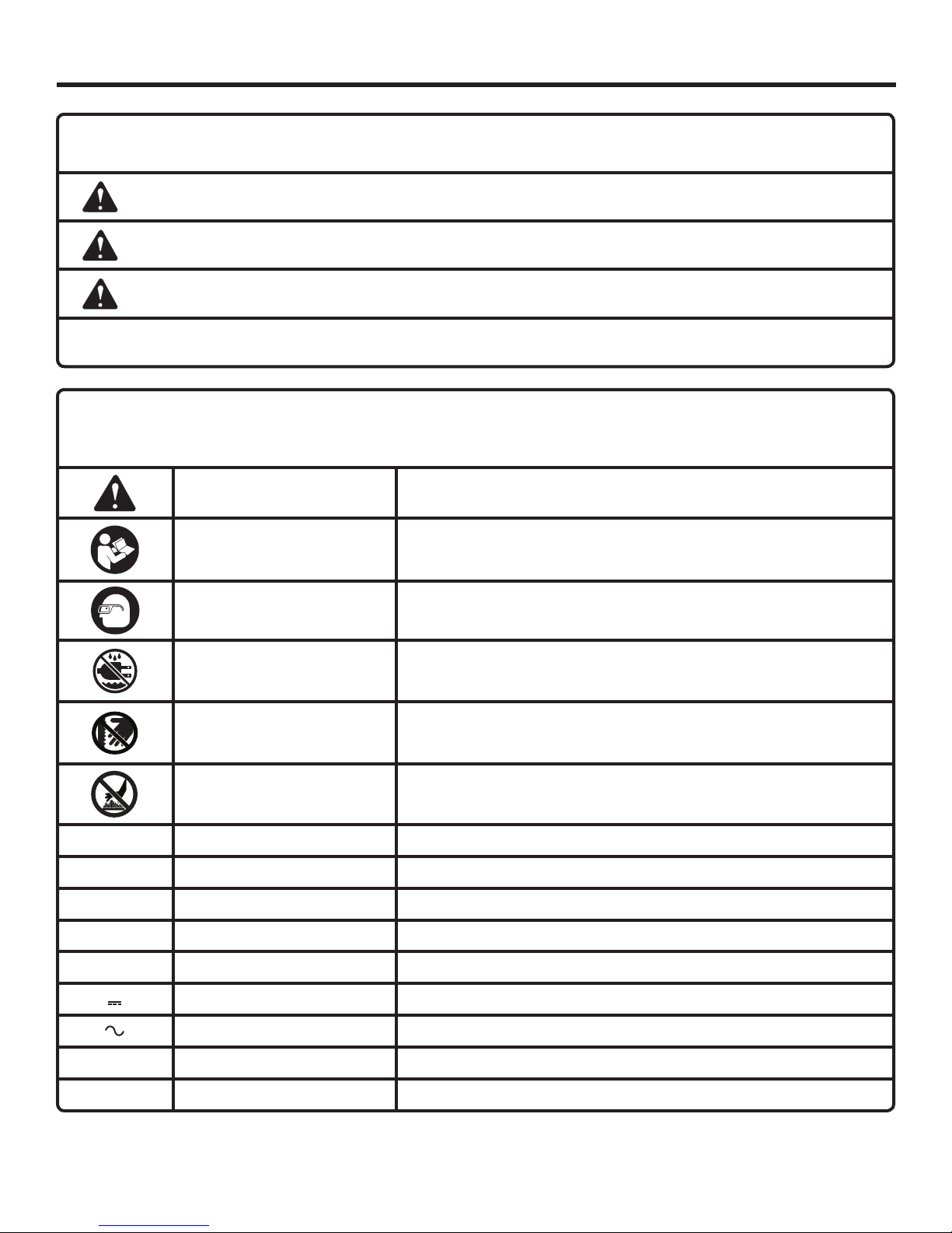
SYMBOL SIGNAL MEANING
DANGER:
WARNING:
CAUTION:
NOTICE:
Some of the following symbols may be used on this product. Please study them and learn their meaning. Proper interpretation of these symbols will allow you to operate the product better and safer.
Indicates an imminently hazardous situation, which, if not avoided, will result in death or
serious injury.
Indicates a potentially hazardous situation, which, if not avoided, could result in death or
serious injury.
Indicates a potentially hazardous situation, which, if not avoided, may result in minor or
moderate injury.
(Without Safety Alert Symbol) Indicates important information not related to an injury hazard,
such as a situation that may result in property damage.
SYMBOL NAME DESIGNATION/EXPLANATION
Safety Alert Precautions that involve your safety.
Read Operator’s Manual
Eye Protection
To reduce the risk of injury, user must read and understand operator’s
manual before using this product.
Always wear eye protection with side shields marked to comply with
ANSI Z87.1.
Wet Conditions Alert Do not expose to rain or use in damp locations.
No Hands Symbol
Hot Surface
V Volts Voltage
A Amperes Current
Hz Hertz Frequency (cycles per second)
W Watt Power
min Minutes Time
Direct Current Type or a characteristic of current
Alternating Current Type of current
n
o
.../min Per Minute Revolutions, strokes, surface speed, orbits etc., per minute
No Load Speed Rotational speed, at no load
Failure to keep your hands away from the blade will result in serious
personal injury.
To reduce the risk of injury or damage, avoid contact with any hot
surface.
4 - English

FEATURES
PRODUCT SPECIFICATIONS
No Load Speed .............................................................................................................................0-3000 strokes per minute
Stroke Length .................................................................................................................................................. 1/2 in. (13 mm)
KNOW YOUR JOBMAX™ JIG SAW HEAD
See Figure 1, page 10.
The safe use of this product requires an understanding of
the information on the product and in this operator’s manual
as well as a knowledge of the project you are attempting.
Before use of this product, familiarize yourself with all operating features and safety rules.
BI-DIRECTIONAL LOCK-OFF LEVER
The bi-directional lock-off lever reduces the possibility of
accidental starting.
NO-MAR PLATE
The no-mar plate has a smooth finish and can be snapped
on over the metal shoe of the jig saw. This makes it easier to
glide the tool along a delicate work surface without marring it.
BLADE GUARD
The blade guard helps protect the operator from accidental
contact with the saw blade.
TOOL-FREE BLADE CLAMP
There is a convenient lever on the blade clamp for changing
saw blades without the need for separate tools.
BLOWER PORT
The blower port directs debris away from the cut line to
improve line of sight.
CALIFORNIA PROPOSITION 65
WARNING:
This product and some dust created by power sanding, sawing, grinding, drilling, and other construction activities
may contain chemicals, including lead, known by the State of California to cause cancer, birth defects or other
reproductive harm. Wash hands after handling.
Some examples of these chemicals are:
• lead from lead-based paints,
• crystalline silica from bricks and cement and other masonry products, and
• arsenic and chromium from chemically-treated lumber.
Your risk from exposure to these chemicals varies, depending on how often you do this type of work. To reduce
your exposure, work in a well ventilated area and with approved safety equipment, such as dust masks that are
specially designed to filter out microscopic particles.
5 - English

ASSEMBLY
UNPACKING
This product has been shipped completely assembled.
Carefully remove the product and any accessories from
the box. Make sure that all items listed in the packing list
are included.
WARNING:
Do not use this product if it is not completely
assembled or if any parts appear to be missing
or damaged. Use of a product that is not properly
and completely assembled could result in serious
personal injury.
Inspect the product carefully to make sure no breakage
or damage occurred during shipping.
Do not discard the packing material until you have care-
fully inspected and satisfactorily operated the product.
If any parts are damaged or missing, please call
1-866-539-1710 for assistance.
PACKING LIST
Anti-splintering insert
JobMax™ Jig Saw Head
T-Shank Blade (wood)
Operator’s Manual
WARNING:
If any parts are damaged or missing do not operate
this product until the parts are replaced. Use of
this product with damaged or missing parts could
result in serious personal injury.
WARNING:
Do not attempt to modify this product or create
accessories not recommended for use with this
product. Any such alteration or modification is
misuse and could result in a hazardous condition
leading to possible serious personal injury.
WARNING:
To prevent accidental starting that could cause
serious personal injury, always remove the battery
pack from the product or disconnect it from the
power supply when assembling parts.
OPERATION
WARNING:
Do not allow familiarity with products to make you
careless. Remember that a careless fraction of a
second is sufficient to inflict severe injury.
WARNING:
Always wear eye protection with side shields
marked to comply with ANSI Z87.1. Failure to do
so could result in objects being thrown into your
eyes, resulting in possible serious injury.
WARNING:
Do not use any attachments or accessories not
recommended by the manufacturer of this product.
The use of attachments or accessories not
recommended can result in serious personal injury.
WARNING:
The product can be used with one or two hands
as shown in figures 7 and 8. Plan your hand
placement so your fingers will not be anywhere a
sudden slip could cause them to slide or fall into
the cutting path.
APPLICATIONS
You may use this product for the purposes listed below:
Cutting all types of wood products (lumber, plywood,
paneling, composition board, and hard board)
Cutting thin sheet metal (metal cutting blade sold separately)
Cutting plastics and laminates
INSTALLING AND REMOVING THE JIG SAW HEAD
See Figure 2, page 10.
To install the jig saw head:
Remove the battery pack from the power base or
disconnect the power base from the power supply.
6 - English

OPERATION
Place the head on the power base and push until the
latches click into position. Pull on the head to make sure
it is securely installed before proceeding.
Reinstall the battery pack or connect the power base to
the power supply.
To remove the jig saw head:
Remove the battery pack from the power base or
disconnect the power base from the power supply.
Depress the latches on the power base and pull the jig
saw head away from the power base.
TURNING THE JIG SAW ON AND OFF
See Figure 3, page 10.
To turn the jig saw on: Slide bi-directional lock-off lever
to the right or to the left, and press the switch trigger on
the power base.
To turn the jig saw off: Release the switch trigger on
the power base.
NOTICE:
Bi-directional lock-off lever should be in the LOCK
(center) position when saw is not in use or is being
transported.
ANTI-SPLINTERING INSERT
See Figures 4 - 5, page 10.
The anti-splintering insert is especially useful when cutting
plywood to reduce splintering. It should only be used when
making straight cuts or circle cuts. It is not for plunge
cutting.
To attach or remove the anti-splintering insert:
Remove the battery pack from the power base or
disconnect the power base from the power supply.
Remove the jig saw head from the power base.
Depress the tab on the no-mar plate and remove it from
the base.
To attach: Slide the anti-splintering insert onto the base
with the notch facing the blade. The grooves on the antisplintering insert should engage the tabs on the base.
Replace the no-mar plate.
To remove: Grab the anti-splintering insert and slide it
away from the jig saw base. Replace the no-mar plate.
INSTALLING AND REMOVING BLADES
See Figure 6, page 10.
NOTE: The jig saw is designed to use T-shank and U-shank
blades only.
To install blades:
Remove the battery pack from the power base or
disconnect the power base from the power supply.
If attached, remove the anti-splintering insert.
Lift the tool-free blade clamp until it stops.
Holding the tool-free blade clamp up, insert the saw
blade as far as possible into the slot in the blade clamp
body and roller guide.
Check to make sure the back of the saw blade is
centered in the groove of the roller guide and blade
clamp body.
Release the tool-free blade clamp lever. Make sure the
blade is securely in place.
NOTE: Do not use the tool if the blade is not installed
correctly.
Reinstall the battery pack or connect the power base to
the power supply.
To remove blades:
Remove the battery pack from the power base or
disconnect the power base from the power supply.
If attached, remove the anti-splintering insert.
Lift the tool-free blade clamp until it stops.
Holding the tool-free blade clamp up, remove the saw
blade.
GENERAL CUTTING
See Figure 7, page 11.
Rest the front of the jig saw base on the workpiece and align
cutting edge of the blade with the line on your workpiece.
Start the power base and move it forward on the work
surface. Apply downward pressure to keep the jig saw
steady and only enough forward pressure to keep the blade
cutting. Do not force the tool. Forcing the tool may overheat
the motor and break saw blades. Broken and dull (or worn)
saw blades must be replaced with new saw blades.
STRAIGHT CUTTING
See Figure 8, page 11.
A straight cut can be made by clamping a piece of wood or
straightedge to the workpiece and guiding the edge of the
jig saw against it. Make the cut from one direction only; don’t
cut halfway and complete the cut from the opposite end.
SCROLL CUTTING
See Figure 9, page 11.
NOTE: Do not use the anti-splintering insert when making
scroll cuts, plunge cuts, and when cutting metal.
Scroll cuts can be made with the jig saw by guiding the direction
of the cut with applied pressure on the handle as shown.
WARNING:
To prevent accidental starting that could cause
serious personal injury, always remove the battery
pack from the product or disconnect it from the
power supply when assembling parts.
7 - English

OPERATION
PLUNGE CUTTING
See Figure 10 - 12, page 11.
Depending on the thickness of the material being cut, you
may need to drill a pilot hole before making plunge cuts.
WARNING:
To avoid loss of control, broken blades, or damage
to the material being cut, always use extreme
caution when making plunge cuts. We do not
recommend plunge cutting on materials other
than wood.
To make plunge cuts using pilot holes:
Mark the line of cut clearly on the workpiece.
Drill a pilot hole inside the area marked by the line of
cut. The pilot hole should be large enough to slide the
blade through the material.
Slowly lower the blade through the pilot hole in the
workpiece until the base contacts the work piece. Fully
squeeze the switch trigger to start the saw.
MAINTENANCE
Do not move the base forward until the blade is entirely
through the workpiece and the base is in complete
contact with the workpiece.
Move the saw forward to complete the opening.
To make plunge cuts without using pilot holes:
Mark the line of cut clearly on the workpiece.
Tilt the jig saw forward so that it rests on the front edge
of the base and blade will not come in contact with the
workpiece when the tool is turned on.
Make sure the blade is aligned with the area to be cut.
Fully squeeze the switch trigger and slowly lower the
blade into the workpiece until the blade cuts through
the workpiece.
Continue lowering the blade into the workpiece until the
base rests flat on the work surface, then move the jig
saw forward to complete the opening.
Use only the 7 teeth per inch blade for this type of cut.
WARNING:
When servicing use only identical RIDGID®
replacement parts. Use of any other parts may
create a hazard or cause product damage.
WARNING:
Always wear eye protection with side shields
marked to comply with ANSI Z87.1. Failure to do
so could result in objects being thrown into your
eyes, resulting in possible serious injury.
WARNING:
To avoid serious personal injury, always remove the
battery pack from the power base or disconnect
the power base from the power supply when
cleaning or performing any maintenance.
FIGURES (ILLUSTRATIONS) START ON PAGE 10
GENERAL MAINTENANCE
Avoid using solvents when cleaning plastic parts. Most
plastics are susceptible to damage from various types of
commercial solvents and may be damaged by their use. Use
clean cloths to remove dirt, dust, oil, grease, etc.
WARNING:
Do not at any time let brake fluids, gasoline,
petroleum-based products, penetrating oils, etc.,
come in contact with plastic parts. Chemicals can
damage, weaken or destroy plastic which may
result in serious personal injury.
AFTER FRENCH AND SPANISH LANGUAGE SECTIONS.
8 - English

WARRANTY
RIDGID® HAND HELD AND STATIONARY POWER TOOL 3 YEAR LIMITED SERVICE
WARRANTY
Proof of purchase must be presented when requesting warranty service.
Limited to RIDGID® hand held and stationary power tools
purchased 2/1/04 and after. This product is manufactured
by One World Technologies, Inc. The trademark is licensed
from RIDGID®, Inc. All warranty communications should be
directed to One World Technologies, Inc., attn: RIDGID®
Hand Held and Stationary Power Tool Technical Service at
(toll free) 1-866-539-1710.
90-DAY SATISFACTION GUARANTEE POLICY
During the first 90 days after the date of purchase, if you are
dissatisfied with the performance of this RIDGID® Hand Held
and Stationary Power Tool for any reason you may return
the tool to the dealer from which it was purchased for a full
refund or exchange. To receive a replacement tool you must
present proof of purchase and return all original equipment
packaged with the original product. The replacement tool
will be covered by the limited warranty for the balance of
the 3 YEAR service warranty period.
WHAT IS COVERED UNDER THE 3 YEAR
LIMITED SERVICE WARRANTY
This warranty on RIDGID® Hand Held and Stationary Power
Tools covers all defects in workmanship or materials and normal wear items such as brushes, chucks, motors, switches,
cords, gears and even cordless batteries in this RIDGID®
tool for three years following the purchase date of the tool.
Warranties for other RIDGID® products may vary.
HOW TO OBTAIN SERVICE
To obtain service for this RIDGID® tool you must return it;
freight prepaid, or take it in to an authorized service center
for RIDGID® branded hand held and stationary power tools.
You may obtain the location of the authorized service center nearest you by calling (toll free) 1-866-539-1710 or by
logging on to the RIDGID® website at www.RIDGID.com.
When requesting warranty service, you must present the
original dated sales receipt. The authorized service center
will repair any faulty workmanship, and either repair or replace any part covered under the warranty, at our option, at
no charge to you.
WHAT IS NOT COVERED
This warranty applies only to the original purchaser at retail
and may not be transferred. This warranty only covers defects arising under normal usage and does not cover any
malfunction, failure or defect resulting from misuse, abuse,
neglect, alteration, modification or repair by other than an
authorized service center for RIDGID® branded hand held
and stationary power tools. Consumable accessories provided with the tool such as, but not limited to, blades, bits
and sand paper are not covered.
RIDGID, INC. AND ONE WORLD TECHNOLOGIES, INC.
MAKE NO WARRANTIES, REPRESENTATIONS OR
PROMISES AS TO THE QUALITY OR PERFORMANCE
OF ITS POWER TOOLS OTHER THAN THOSE SPECIFICALLY STATED IN THIS WARRANTY.
ADDITIONAL LIMITATIONS
To the extent permitted by applicable law, all implied warranties, including warranties of MERCHANTABILITY or FITNESS
FOR A PARTICULAR PURPOSE, are disclaimed. Any implied
warranties, including warranties of merchantability or fitness
for a particular purpose, that cannot be disclaimed under
state law are limited to three years from the date of purchase.
One World Technologies, Inc. and RIDGID®, Inc. are not
responsible for direct, indirect, incidental or consequential
damages. Some states do not allow limitations on how long
an implied warranty lasts and/or do not allow the exclusion
or limitation of incidental or consequential damages, so the
above limitations may not apply to you. This warranty gives
you specific legal rights, and you may also have other rights
which vary from state to state.
9 - English
 Loading...