

Page 1
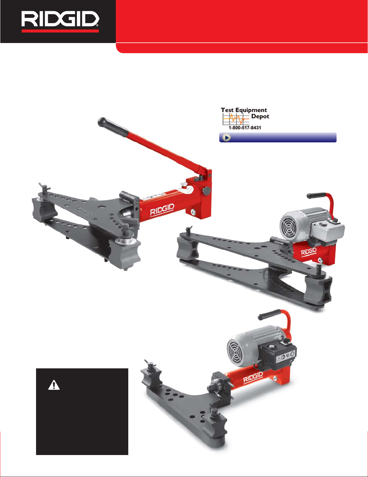
Hydraulic Pipe Bender
Pipe Bender Manual
WARNING!
Read this Operator’s Manual
carefully before using this
tool. Failure to understand
and follow the contents of
this manual may result in
electrical shock, fire and/or
serious personal injury.
99 Washington Street
Melrose, MA 02176
Phone 781-665-1400
Toll Free 1-800-517-8431
Visit us at www.TestEquipmentDepot.com
Page 2

ii
Hydraulic Pipe Bender
Table of Contents
Recording Form For Machine Serial Number ............................................................................................................1
Safety Symbols..............................................................................................................................................................2
General Safety Rules
Work Area Safety........................................................................................................................................................2
Electrical Safety ..........................................................................................................................................................2
Personal Safety ..........................................................................................................................................................3
Power Tool Use And Care ..........................................................................................................................................3
Service........................................................................................................................................................................3
Specific Safety Information
Hydraulic Pipe Bender Safety ....................................................................................................................................3
Description And Specifications
Description..................................................................................................................................................................4
Icons ..........................................................................................................................................................................4
Specifications ..........................................................................................................................................................5-6
Pre-Operation Inspection ............................................................................................................................................6
Machine And Work Area Set-Up ..................................................................................................................................7
Powering The Electric Bender ....................................................................................................................................8
Operating Instructions
Loading The Pipe........................................................................................................................................................8
Advancing/Retracting The Ram..................................................................................................................................9
Bending The Pipe ......................................................................................................................................................9
Straightening Bends..................................................................................................................................................11
Maintenance Instructions
Cleaning....................................................................................................................................................................11
Lubrication ................................................................................................................................................................11
Hydraulic Oil..............................................................................................................................................................11
Low Temperature Operating ....................................................................................................................................12
Accessories ................................................................................................................................................................12
Machine Storage and Transportation........................................................................................................................12
Service And Repair ....................................................................................................................................................12
Disposal ......................................................................................................................................................................13
Troubleshooting..........................................................................................................................................................14
Lifetime Warranty ........................................................................................................................................Back Cover
*Original Instructions - English
Page 3

Hydraulic Pipe Bender
Record Serial Number below and retain product serial number which is located on nameplate.
Serial
No.
Hydraulic Pipe Bender
Pipe Bender
Page 4
2
Hydraulic Pipe Bender
General Safety Rules*
WARNING
Read all safety warnings and instructions. Failure
to follow the warnings and instructions may result
in electric shock, fire and/or serious injury.
SAVE ALL WARNINGS AND INSTRUCTIONS
FOR FUTURE REFERENCE!
The term "power tool" in the warnings refers to your
mains-operated (corded) power tool or battery-operated
(cordless) power tool.
Work Area Safety
• Keep your work area clean and well lit. Cluttered or
dark areas invite accidents.
• Do not operate power tools in explosive atmo-
spheres, such as in the presence of flam mable
liquids, gases, or dust. Power tools create sparks
which may ignite the dust or fumes.
• Keep children and by-standers away while oper-
ating a power tool. Distractions can cause you to lose
control.
Electrical Safety
• Power tool plugs must match the outlet. Never
modify the plug in any way. Do not use any adap ter plugs with earthed (grounded) power tools.
Un modified plugs and matching outlets will reduce
risk of electric shock.
• Avoid body contact with earthed or grounded sur-
faces such as pipes, radiators, ranges and refrigerators. There is an increased risk of electrical shock
if your body is earthed or grounded.
• Do not expose power tools to rain or wet condi-
tions. Water entering a power tool will increase the risk
of electrical shock.
• Do not abuse the cord. Never use the cord for
carrying, pulling or unplugging the power tool.
Keep cord away from heat, oil, sharp edges or
moving parts. Damaged or entangled cords increase
the risk of electric shock.
• When operating a power tool outdoors, use an
extension cord suitable for outdoor use. Use of a
cord suitable for outdoor use reduces the risk of electric shock.
• If operating a power tool in a damp location is
unavoidable, use a ground fault circuit interrupter
(GFCI) protected supply. Use of a GFCI reduces the
risk of electric shock.
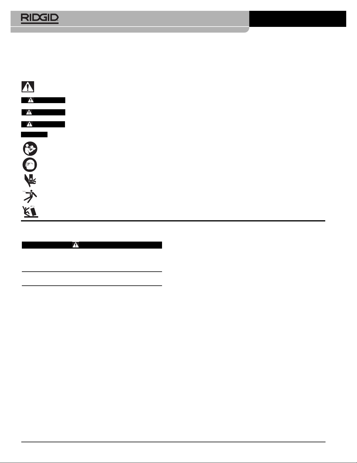
Safety Symbols
In this operator’s manual and on the product, safety symbols and signal words are used to communicate important safety information. This section is provided to improve understanding of these signal words and symbols.
This is the safety alert symbol. It is used to alert you to potential personal injury hazards. Obey all safety messages that follow this
symbol to avoid possible injury or death.
DANGER indicates a hazardous situation which, if not avoided, will result in death or serious injury.
WARNING indicates a hazardous situation which, if not avoided, could result in death or serious injury.
CAUTION indicates a hazardous situation which, if not avoided, could result in minor or moderate injury.
NOTICE indicates information that relates to the protection of property.
This symbol means read the operator’s manual carefully before using the equipment. The operator’s manual contains
important information on the safe and proper operation of the equipment.
This symbol means always wear safety glasses with side shields or goggles when handling or using this equipment to reduce
the risk of eye injury.
This symbol indicates the risk of hands, fingers or other body parts being crushed.
This symbol indicates the risk the electrical shock.
NOTICE
DANGER
WARNING
CAUTION
This symbol indicates the risk of machine tipping, causing striking or crushing injuries.
* The text used in the General Safety Rules section of this manual is verbatim, as required, from the applicable CSA 745/UL 45 standard. This section contains
general safety practices for many different types of power tools. Not every precaution applies to every tool, and some do not apply to this tool.
Page 5

3
Personal Safety
• Stay alert, watch what you are doing and use com-
mon sense when operating a power tool. Do not
use a power tool while you are tired or under the
influence of drugs, alcohol, or medication. A mo -
ment of inattention while operating power tools may
result in serious personal injury.
• Use personal protective equipment. Always wear
eye protection. Protective equipment such as dust
mask, non-skid safety shoes, hard hat, or hearing
protection used for appropriate conditions will reduce
personal injuries.
• Prevent unintentional starting. Ensure the switch
is in the off-position before connecting to power
source and/or battery pack, picking up or carrying
the tool. Carrying power tools with your finger on the
switch or energizing power tools that have the switch
on invites accidents.
• Remove any adjusting key or wrench before turn-
ing the power tool ON. A wrench or a key left
attached to a rotating part of the power tool may result
in personal injury.
• Do not overreach. Keep proper footing and bal-
ance at all times. This enables better control of the
power tool in unexpected situations.
• Dress properly. Do not wear loose clothing or
jewel ry. Keep your hair, clothing, and gloves away
from moving parts. Loose clothes, jewelry, or long
hair can be caught in moving parts.
• If devices are provided for the connection of dust
extraction and collection facilities, ensure these are
connected and properly used. Use of dust collection
can reduce dust-related hazards.
Power Tool Use And Care
• Do not force power tool. Use the correct power tool
for your application. The correct power tool will do the
job better and safer at the rate for which it is designed.
• Do not use power tool if the switch does not turn it
ON and OFF. Any power tool that cannot be controlled with the switch is dangerous and must be
repaired.
• Disconnect the plug from the power source and/or
the battery pack from the power tool before making any adjustments, changing accessories, or
storing power tools. Such preventive safety mea-
sures reduce the risk of starting the power tool accidentally.
Hydraulic Pipe Bender
• Store idle power tools out of the reach of children
and do not allow persons unfamiliar with the pow er tool or these instructions to operate the power
tool. Power tools are dangerous in the hands of un -
trained users.
• Maintain power tools. Check for misalignment or
binding of moving parts, breakage of parts and any
other condition that may affect the power tool’s op er ation. If damaged, have the power tool repaired
before use. Many accidents are caused by poorly
maintained power tools.
• Keep cutting tools sharp and clean. Properly main-
tained cutting tools with sharp cutting edges are less
likely to bind and are easier to control.
• Use the power tool, accessories and tool bits etc.
in accordance with these instructions, taking into
account the working conditions and the work to be
performed. Use of the power tool for operations dif-
ferent from those intended could result in a hazardous
situation.
Service
• Have your power tool serviced by a qualified repair
person using only identical replacement parts.
This will ensure that the safety of the power tool is
maintained.
Specific Safety Information
WARNING
This section contains important safety information
that is specific to this tool.
Read these precautions carefully before using the
RIDGID
®
Hydraulic Pipe Benders to reduce the
risk of crushing injuries, electric shock or other
serious personal injury.
SAVE THESE INSTRUCTIONS!
Keep this manual with the hydraulic bender for use by the
operator.
Hydraulic Pipe Bender Safety
• Keep your fingers and hands away from the bend-
ing attachments and work piece during bending.
Your fingers, hands and other body parts can be
caught, crushed, fractured or amputated if they be come
entangled in the bender or between these components and any other object.
• Properly support the tool and pipe. This will help to
prevent the tipping of the pipe and equipment.
Page 6

• BS 1387 Medium and Heavy Series
• GB/3091 (ISO 559) Medium and Heavy Series
Pipe with thicker walls and/or high hardness (over 75
HRb)/strength (over 66 ksi/455 MPa Tensile) may not be
able to be bent. Pipe with comparable outside diameter and
wall thickness to the pipes listed may be able to be bent
depending on pipe material characteristics. Pipe with thinner walls can be bent but may experience issues with
kinking or buckling in the bend area.
Figure 1 – Hydraulic Pipe Bender 2" and 3" Manual Unit
Figure 2 – Hydraulic Pipe Bender 2" and 3" Electric Unit
• Pipe moves during bending and can cause striking
or crushing injuries. Be sure there is adequate clear-
ance around the pipe before bending.
• Hydraulic benders use high pressure fluid to gen-
erate large forces. High pressure fluid can penetrate skin. Large forces can break and throw parts,
causing serious injury. Stand clear of the unit during
use and always wear appropriate protective equipment, including eye protection.
• One person must control the work process and
machine operation. Only the operator should be in
the work area when the machine is operating. This
helps reduce the risk of injury.
• Read and understand this manual, and the warn-
ings and instructions for all equipment being used
with this tool before operating. Failure to follow all
warnings and instructions may result in property damage and/or serious injury
• Use the Hydraulic Pipe Bender only with RIDGID
Hydraulic Pipe Bender attachments as directed
in these instructions. Other uses or modifying the
Hydraulic Pipe Benders may damage the tool, the
attachments or cause personal injury.
The EC Declaration of Conformity (890-011-320.10) will
accompany this manual as a separate booklet when
required.
If you have any question concerning this RIDGID®product:
– Contact your local RIDGID distributor.
– Visit www.RIDGID.com or www.RIDGID.eu to find
your local RIDGID contact point.
– Contact RIDGID Technical Services Department at
rtctechservices@emerson.com, or in the U.S. and
Canada call (800) 519-3456.
Description And Specifications
Description
RIDGID®Hydraulic Pipe Benders allow precision cold
bend ing of metallic pipe from 1/4" to 3" (depending on the
unit). The tip-up wing configuration of the RIDGID Hydraulic
Bender allows easy access to the pipe for set up and
removal. Benders are available in both manual and electric versions. An open wing version is available for ease of
pipe loading and unloading.
The RIDGID Hydraulic Benders are generally designed to
bend the following types of pipe:
• EN 10255 Medium and Heavy Series
• ASTM A53 Schedule 40 and 80
• DIN 2440, 2441 Series
4
Hydraulic Pipe Bender
Do not dispose of
electrical equipment
with household waste
Power ON
Power OFF
Icons
Fill Port
Bending
Frame
Corner
Supports
U-Bracket
Cylinder
Formers
Straightening
Former
Pins
Pump Handle
Weight
Page 7

The machine serial number is located on the side
of the pump. The last 4 digits indicates the month and
year of the manufacture. (03 = month, 10 = year).
Selection of appropriate materials and installation, joining and forming methods is the responsibility of
the system designer and/or installer. Selection of improper materials and methods could cause system failure.
Stainless steel and other corrosion resistant materials
can be contaminated during installation, joining and forming. This contamination could cause corrosion and premature failure. Careful evaluation of materials and meth ods
for the specific service conditions, including chemical and
temperature, should be completed before any installation
is attempted.
Figure 3 – Open Wing Bender
Figure 4 – Machine Serial Number
5
Hydraulic Pipe Bender
NOTICE
Pump Ram Motor
Approximate
Shipping Crate
Model Capacity
Pressure Force
Pump Equipment Standard
Weight Dimensions
No. Inch
(bar) kN(klb)
Type Volt & Power Dimensions Formers
L x W x H (cm)
Frequency kW L x W x H (cm) lb kg
HB382 3/8" - 2" 450 90 (20.1) Manual N/A N/A 73 x 63.5 x 62 3/8", 1/2", 3/4", 1", 159 72 82 x 33 x 49.5
28.8" x 25" x 24.4" 1
1
/4", 11/2", 2" 32.3" x 13" x 19.5"
HB382E 3/8" - 2" 450 90 (20.1) Electric 230/50Hz 1
Φ 1.4 73 x 63.5 x 43 3/8", 1/2", 3/4", 1", 211 96 82 x 39.5 x 60
230/60Hz 3
Φ 1.5 28.8" x 25" x 16.9" 1
1
/4", 11/2", 2" 32.3" x 15.6" x 23.6"
115/60Hz 1
Φ 1.4
400/50Hz 3
Φ 1.5
HB383 3/8" - 3" 450 146 (32.7) Manual N/A 75.5 x 103 x 62 3/8", 1/2", 3/4", 1", 344 156 117 x 37.5 x 49.5
29.8" x 40.6" x 24.4" 1
1
/4", 11/2", 2", 21/2", 3 46.1" x 14.8" x 19.5"
HB383E 3/8" - 3" 450 146 (32.7) Electric 230/50Hz 1
Φ 1.4 75.5 x 103 x 62 3/8", 1/2", 3/4", 1" 401 182 117 x 46.5 x 62
230/60Hz 3
Φ 1.5 29.8" x 40.6" x 24.4" 1
1
/4", 11/2", 2", 21/2", 3 46.1" x 18.3" x 24.1"
115/60Hz 1
Φ 1.4
400/50Hz 3
Φ 1.5
HBO382 3/8" - 2" 450 90 (20.1) Manual N/A N/A 70.5 x 65 x 62 3/8", 1/2", 3/4", 1", 202 92 82 x 33 x 49.5
28" x 25.5" x 24" 1
1
/4", 11/2", 2" 32.3" x 13" x 19.5"
HBO382E 3/8" - 2" 450 90 (20.1) Electric 230/50Hz 1
Φ 1.4 70.5 x 65 x 43 3/8", 1/2", 3/4", 1" 255 116 82 x 39.5 x 60
230/60Hz 3
Φ 1.5 28" x 25.5" x 16.9" 1
1
/4", 11/2", 2" 32.3" x 15.6" x 23.6"
115/60Hz 1
Φ 1.4
400/50Hz 3
Φ 1.5
Specifications
Pipe Bender
Date Code
Page 8

Pre-Operation Inspection
WARNING
Before each use, inspect your pipe bender and correct any problems to reduce the risk of serious
injury from electric shock, crushing injuries and
other causes and prevent machine damage.
1. If an electric bender, make sure the ON/OFF switch
is in the OFF ( ) position and the power cord is un plugged.
2. Clean any oil, grease or dirt from the pipe bender,
including the handles and controls. This allows better
inspection of the pipe bender and helps prevent the
pipe bender or control from slipping from your grip
during use.
3. Inspect the bender for:
• Hydraulic leaks. Check the hydraulic fluid level and
adjust as needed
(see Maintenance Section)
.
• Any broken, cracked, bent, missing, misarranged or
binding parts or any other condition that may prevent the safe and normal operation of the bender.
6
Hydraulic Pipe Bender
All benders come with appropriate formers and corner supports for the size range, and are packaged in a reusable
wooden crate. Formers are for pipes to EN10255 and equivalent as listed below:
Catalog
Nominal Pipe Size Pipe O.D. Wall Thickness Bend Radius* Weight
Pipe**
MIN MAX.
No. Inch Inch mm
Inch mm Inch mm
Inch mm lbs kg Type/Standard
37218 1/4" 0.540 13,5 0.08 2,2 0.16 4 2.36 60 2.2 1 EN10255, ASTM A53
37223 3/8" 0.675 17,2 0.09 2,3 0.16 4 1.77 45 1.8 0,8 EN10255, ASTM A53
37228 1/2" 0.840 21,3 0.10 2,6 0.16 4 1.97 50 2.4 1,1 EN10255, ASTM A53
37233 3/4" 1.050 26,9 0.10 2,6 0.16 4 3.15 80 4.0 1,8 EN10255, ASTM A53
37238 1" 1.315 33,7 0.13 3,2 0.20 5 4.33 110 4.0 1,8 EN10255, ASTM A53
37243 1
1
/4" 1.660 42,4 0.13 3,2 0.20 5 5.31 135 4.6 2,1 EN10255, ASTM A53
37248 1
1
/2" 1.990 48,3 0.13 3,2 0.20 5 6.10 155 9.5 4,3 EN10255, ASTM A53
37253 2" 2.375 60,3 0.14 3,6 0.22 5,5 8.66 220 14.4 6,5 EN10255, ASTM A53
37258 2
1
/2" 2.875 76,1 0.14 3,6 0.28 7 12.60 320 38.5 17,5 EN10255, ASTM A53
37263 3" 3.500 88,9 0.16 4,0 0.30 7,6 15.35 390 59.9 27,2 EN10255, ASTM A53
Former
* Bend radius to centerline of pipe. ** See description for more information.
Specifications
(continued)
Operating Temperature: 14°F to 122°F (-10°C to 50°C)
(See Maintenance Section for more information.)
• Cracks or breaks in the formers and corner supports.
• Inspect the power cord and plug for damage or
modification, such as cuts or a missing ground
plug.
• Presence and legibility of the warning label.
See
Figure 5A and 5B.
If any issues are found during the inspection of the
bender, do not use until those issues have been
corrected.
Figure 5A – Warning Label (Manual)
Page 9

7
Figure 5B – Warning Label (Electric)
4. If any other equipment is being used, inspect and
maintain per its instructions to make sure it functions properly.
Machine And Work Area Set-Up
WARNING
Set up the bender and work area according to
these procedures to reduce the risk of injury from
electric shock, machine tipping, crushing and other
causes, and to help prevent bender damage.
1. Locate a work area that has:
• Adequate lighting.
• No flammable liquids, vapors or dust that may
ignite. The equipment is not explosion proof and
can cause sparks.
• Clear level, stable, dry location for all of the equip-
ment and the operator.
• Properly grounded electrical outlet of proper voltage.
If in doubt, have outlet inspected by licensed electrician.
2. Clean the work area before setting up any equipment. Wipe up any oils or liquids. Clear anything
that the pipe could hit during bending.
3. Inspect the pipe to be bent and installation area and
confirm that you have the correct tool and formers for
the job.
See the Specifications Section.
Do not at tempt to bend pipe that exceeds the pipe bender
specifications. This could damage the pipe bender.
4. Confirm that equipment to be used has been properly
inspected.
Hydraulic Pipe Bender
Figure 6 – Assembling 2" and 3" Benders
5. Assembly
All benders should be set up on the floor or other
suitable surface. Bender parts are heavy and awkward. Use appropriate transport and lifting methods.
If using the accessory wheel stand or turnable tripod,
follow instructions for proper set-up.
• Place the bending frame with the hinged side up.
• Insert the end of the cylinder into the opening at the
end of the bending frame. Align the groove on the
cylinder with the back of the bending frame.
• Fully insert the U-bracket through the joint between
the bending frame and the cylinder.
• Place the corner supports on the lower bending
frame over the appropriate holes for the size of
pipe to be bent.
• Insert the pins through the bending frames to retain
the corner supports.
Figure 7 – Assembled 2"/3" Electric Bender
Bending
Frame
Fully Insert
U-Bracket
Cylinder
Insert Cylinder
Into The Frame
Hinge
Page 10

3. Check the bender for proper operation.
Move the ON/OFF switch to the ON ( ) position.
Press and release the Run switch. If the ON/OFF
switch and Run switch do not control the motor operation, do not use the bender until it has been repaired.
Depress and hold the Run switch. Inspect for misalignment, binding, odd noises or any other unusual
conditions. Release Run switch. If any unusual conditions are found, do not use the machine until it has
been repaired.
Move the ON/OFF switch to the OFF ( ) position.
Operating Instructions
WARNING
Keep your fingers and hands away from the bending attachments and work piece during bending.
Your fingers, hands and other body parts can be
caught, crushed, fractured or amputated if they
become entangled in the bender or between these
components and any other object.
Properly support the tool and pipe. This will help to
prevent the tipping of the pipe and equipment.
Pipe moves during bending and can cause striking
or crushing injuries. Be sure there is adequate
clearance around the pipe before bending
Follow operating instructions to reduce the risk of
injury from entanglement, striking, crushing, electrical shock and other causes.
Loading The Pipe
1. Confirm that the equipment and work area has been
properly set up and is free of by-standers and other
distractions. Confirm ON/OFF switch is on the OFF
( ) position.
2. If needed, mark the pipe to be bent at the appropriate
location.
3. If needed, open the upper bending frame.
4. Choose the appropriate bending former for the pipe to
be bent. Formers are marked with the size and catalog number.
See the Specifications for more infor-
mation
. Place former over the end of the ram.
5. Place the pipe to be bent in front of the former and if
needed place supports under the pipe to hold it in the
correct position for bending. The former includes a
8
Hydraulic Pipe Bender
Figure 8 – Assembled Open Wing Bender
6. Open the fill cap on the cylinder two full turns. This
allows air into the reservoir during use for proper
operation.
(See Figure 11.)
Powering The Electric Bender
1. Confirm that the ON/OFF ( / ) switch is in the OFF
( ) position.
2. Makes sure that the power cord is routed away from
the work area. Run the cord along a clear path to
the outlet, and with dry hand plug in. Keep all connections dry and off the ground. If the power cord is not
long enough, use an extension cord that:
• Is in good condition
• Has a plug similar to that on the tool.
• Is rated for outdoor use and contains a W or W-A in
the cord designation (i.e. SOW
), or complies with
H05VV-F, H05RN-F types or IEC type design
(60227 IEC 53, 60245 IEC 57).
• Has sufficient wire size (16 AWG (1.5mm
2
) for 50'
(15.2m) or less, 14 AWG (2.5mm2) for 50' – 100'
(15.2m – 30.5m) long). Undersized wires can overheat, melting the insulation or causing a fire or
other damage.
Figure 9 – Electric Bender Controls
Run
Switch
Circuit
Breaker
ON/OFF
Switch
Page 11

9
mark at the center for alignment. Properly support the
pipe to prevent tipping of the pipe and the bender
throughout use.
6. Apply grease to the side of the corner support that
contacts the pipe. Place the supports at the appropriate holes as marked on the bending frame. The
corner supports must be located in the correct, symmetrical holes or the bender can be damaged during
use.
Figure 10 – Loading the Pipe
7. Close the bending frame and fully insert the corner
support pins through both wings of the bending frame.
Align the corner supports so that the zero marks on
the angle indicators line up with the mark on the
upper wing
(See Figure 12)
.
Open wing benders do not have angle indicators.
Make sure the pins are fully inserted into the lower
wing.
8. Confirm that the bender and pipe are stable.
Advancing/Retracting The Ram
Turn the release knob clockwise on the hydraulic pump to
the closed (advance ram) position
(See Figure 11.)
To
retract ram, turn release knob counter clockwise to retract
position. An internal spring will retract the ram.
Manual Pump
Move the pump handle up and down to advance the ram.
Do not use handle extensions. This can damage the handle or slip during use and cause injury.
Hydraulic Pipe Bender
Figure 11 – Release Knob Positions (Advance/Retract)
Electric Pump
Move the ON/OFF switch to the ON ( ) position. Press the
RUN switch to ADVANCE the ram. Place ON/OFF switch
in OFF ( ) position when not in use or retracting the ram.
Bending The Pipe
1. Stand next to the cylinder on the same side as the
Release knob. Do not reach over the machine to
operate. Advance the ram. When the bending former touches the pipe, slowly and carefully advance the
ram while aligning the bend location with the former.
Continue advancing the ram until the pipe is just
against the corner supports. Do not place your fingers,
hands or other body parts in a position that would
allow them to be trapped or crushed.
2. Confirm that the corner supports are in the correct
position (as marked on the frame) for the pipe to be
bent and the pins are fully inserted in the frame
(See
Figure 12)
. If not, the bender can be damaged during
use. Make sure that the ends of the pipe extend past
the corner supports enough to prevent the pipe from
slipping off during bending.
See Chart 1.
Chart 1 – Minimum Pipe Length Past The Center Of
The Pin
Advance
Retract
Oil Fill
Port
Pipe Size Min. Distance
O.D. Center Line of Pin to End of Pipe
Inch mm Inch mm
1
/
4
13,5 1.6 40
3
/
8
17,2 1.6 40
1
/
2
21,3 1.9 47
3
/
4
26,9 2.0 51
1 33,7 2.1 54
1
1
/
4
42,4 2.3 58
1
1
/
2
48,3 2.5 63
2 60,3 2.2 56
2
1
/
2
76,1 3.3 84
3 88,9 3.7 93
Page 12

10
Hydraulic Pipe Bender
Figure 15 – Angle Indicator – End of Bend
Watch the ram as it extends. If you can see a small
groove in the ram
(Figure 16)
, stop advancing the ram
to prevent hydraulic leaks and ram damage
4. For certain sizes of pipe (21/2", 3"), a ram extension
must be used to form a 90 degree bend. When the
groove in the ram
(Figure 16)
is visible, stop advancing the ram. Make sure that the pipe is properly supported to prevent it from moving or falling. Turn the
release knob to the retract position, and retract the
ram far enough to allow the extension to be inserted
between the end of the ram and the former. Insert the
extension and carefully advance the ram. Do not
place your fingers, hands or other body parts in a
position that would allow them to be trapped or
crushed.
Figure 16 – Groove in Ram
Groove
Angle
Indicator
Figure 12 – Angle Indicator Alignment – Start of Bend
Figure 13 – Operating the Manual Bender
Figure 14 – Operating the Open Wing Bender
3. Continue to advance the ram and bend the pipe. As
the pipe is bent, the ends will move. Stay clear of
the moving pipe. Monitor the angle indicators
(Figure
15).
The average of the angles measured by each
angle indicator equals the approximate total angle
bent.
Zero Alignment
Pins
Fully
Inserted
In Correct
Position
Pipe Size
Markings
Page 13

Figure 17 – Inserting the Ram Extension (Shown Open
Without Pipe For Clarity)
As the desired degree of bend is reached stop ad vancing the ram. Do not try to create a bend of more
than 90 degrees (per the angle indicator), this could
cause kinking of the pipe and other issues. A square
or other measuring device may be needed to measure exact bend angles. It is preferable to under
bend the pipe as it is easier to bend the pipe a little
more than to straighten it. When the ram is retracted,
the pipe may spring back, so you may need to slightly compensate to get the desired angle.
5. With the bend complete, move the ON/OFF switch to
the OFF ( ) position. Retract the ram by turning the
release knob to the retract position.
6. Remove the pipe from the bender. If needed, remove
pins, corner supports and/or open the top wing. If
the former is stuck to the pipe, a block of wood or a
soft faced hammer can be used to tap the former off
the pipe. Do not use regular hammers, chisels or
other hardened tools to remove the former. They
can chip and damage the former and cause injury.
Straightening Bends
A straightening former is available to slightly reduce the
angle of a bend (up to approximately 10 degrees). Use of
the straightening former may deform the bend. In some
cases (such as 90 degree bends on 2
1
/2" or 3") the
straightening former cannot be used. To use:
1. Place the straightening former on the end of the ram.
2. Place the pipe so that the bend sits against the
straightening former and the legs of the bend are
11
Hydraulic Pipe Bender
Ram
Extension
against the corner supports. Make sure the set up is
symmetric, with the corner supports in the correct
position, to prevent damage to the bender.
Figure 18 – Straightening a Bend
3. Follow the steps for “Bending the Pipe”.
Maintenance Instructions
WARNING
Maintain the hydraulic bender according to these
procedures for a longer product life and to reduce
the risk of injury from electrical shock and other
causes.
Cleaning
After each use, wipe any oil or dirt off of the bender and
formers with a clean, dry, soft cloth. Pay special attention
to the ram and piston to remove any dirt or debris that
could scratch polished parts or damage seals. If needed,
the formers and corner supports can be cleaned with a
wire brush.
Lubrication
Monthly, or more often if needed, apply a light machine oil
or grease to handle pivot points, wing hinge, and pins. Do
not apply oil to hydraulic system components.
Hydraulic Oil
Checking Level/Adding Hydraulic Oil
Before each use, check oil level. Place the bender on a flat
level surface with the ram fully retracted. Remove the oil
vent cap – oil should be even with the bottom of the fill
neck. If oil is needed, add Shell Tellus 32 Hydraulic Oil or
other equivalent high quality hydraulic oil and replace oil
vent cap. See
Figure 10
for location of oil vent cap.
Straightening
Former
Corner Support
Position
Page 14

Accessories
WARNING
To reduce the risk of serious injury, only use accessories specifically designed and recommended for
use with the RIDGID hydrau lic benders, such as
those listed below. Other Accessories suitable for
use with other tools may be hazardous when used
with the RIDGID hydraulic benders.
Machine Storage and
Transportation
The Hydraulic bender must be kept in doors or
well covered in rainy weather. Store the mach ine in a
locked area that is out of the reach of children and people
unfamiliar with hydraulic benders. This machine can
cause serious injury in the hands of untrained users.
Store unit between 14°F (-10°C) and 122°F (50°C).
When preparing to move the hydraulic bender, always
close the fill cap on the cylinder to prevent hydraulic oil
from leaking.
Service And Repair
WARNING
Improper service or repair can make machine un safe to operate.
The “Maintenance Instructions” will take care of most of
the service needs of this machine. Any problems not
addressed by this section should only be handled by an
authorized RIDGID service technician.
Tool should be taken to a RIDGID Independent Author ized Service Center or returned to the factory.
12
Hydraulic Pipe Bender
Catalog
No. Description
37293 Pins, HB382/HB382E
37273 Corner Supports, HB382/HB382E
37603 U-Bracket, HB382/HB382E
37618 Straightening Former, HB382/HB382E/HB383/HB383E
37298 Pins, HB383/HB383E
37278 Corner Supports, HB383/HB383E
37838 U-Bracket, HB383/HB383E
37828 Foot Wheels, HB382/HB382E/HB383/HB383E
37813 Turnable Tripod, HB382/HB382E/HB383/HB383E
38568 Extension, HB383/383E
42533 Corner Supports, HB0382/HB0382E
42543 Pins, HB0382/HB0382E
Hydraulic Pipe Bender Accessories
NOTICE
Changing
Once a year, or more often with heavy use or use in
dusty conditions, the hydraulic oil should be changed.
Place the pump end of the hydraulic cylinder in a container
to collect the hydraulic oil as it is drained. Directly under
the cylinder is a plug
(Figure 19)
. Remove the plug, filter
spring and filter and allow the hydraulic fluid to drain.
Open the oil vent cap and raise the ram end of the cylinder slightly to improve drainage. Complete drainage may
take up to several hours. Properly dispose of the used
hydraulic oil per the Material Safety Data Sheet (MSDS)
and local requirements.
Figure 19 – Hydraulic Oil Drain Plug and Access to Filter
Clean the filter by rinsing in clean hydraulic oil. Re-install
the clean or new filter, spring and plug. Fill the bender with
new hydraulic oil following the instructions for adding
hydraulic oil. Operate the bender through several cycles
to remove air from the system and check the hydraulic oil
level.
Low Temperature Operation
If the Hydraulic Bender will be used in low temperatures
(Less than 14°F (-10°C)) it is recommended that the
Hydraulic oil be changed to a high quality Hydraulic oil suitable for the temperature.
Oil Capacity
HB382/382E, HBO382/382E 1.27 QT./1.2 liter
HB383/383E 1.70 QT./1.6 liter
Page 15

13
Hydraulic Pipe Bender
For information on your nearest RIDGID Independent
Service Center or any service or repair questions:
• Contact your local RIDGID distributor.
• Visit www.RIDGID.com or www.RIDGID.eu to find
your local RIDGID contact point.
• Contact RIDGID Technical Services Department at
rtctechservices@emerson.com, or in the U.S. and
Canada call (800) 519-3456
Disposal
Parts of the hydraulic pipe bender contain valuable materials and can be recycled. There are companies that specialize in recycling that may be found locally. Dispose of
the com ponents in compliance with all applicable regulations. Contact your local waste management authority
for more information.
For EC Countries: Do not dispose of electrical equipment with household waste!
According to the European Guideline 2002/ 96/ EC for Waste Electrical and Electronic
Equipment and its implemen tation into nation-
al legislation, electrical equipment that is no
longer usable must be collected separately and disposed
of in an environmentally correct manner.
Page 16

14
Hydraulic Pipe Bender
PROBLEM POSSIBLE REASONS SOLUTION
Ram Does Not Advance.
Motor Does Not Start.
Oil Leaks.
Pipe Kinks Or Buckles.
Pipe Won't Bend.
Troubleshooting
Release Knob Not Fully Closed.
Fill Cap Is Closed.
Low Oil Level.
Clogged Oil Filter.
Air In Hydraulic System.
Seals Are Worn/Damaged.
Power Supply Not Connected.
Motor Too Hot.
Circuit Breaker Open.
Seals Are Worn/Damaged.
Pipe Wall Is Too Thin.
Former is wrong size for pipe.
Ram Does Not Advance.
Pipe Wall Too Thick/Pipe Too Hard.
Close Release Knob.
Open Fill Cap Two Full Turns.
Check Oil Level.
Change Hydraulic Oil/Clean Filter.
Operate Bender Unloaded To Remove Air From
System.
Have Bender Serviced.
Connect Power Supply.
Allow Motor To Cool Down.
Depress Circuit Breaker Reset On Motor Control.
Check Power Supply Circuit Breaker.
Have Bender Serviced.
See Description/Specification Section.
Use correct former.
See Above.
See
Description/Specification
Section.
Test Equipment Depot - 800.517.8431 - 99 Washington Street Melrose, MA 02176
TestEquipmentDepot.com
 Loading...