

Page 1
OPERATOR’S MANUAL
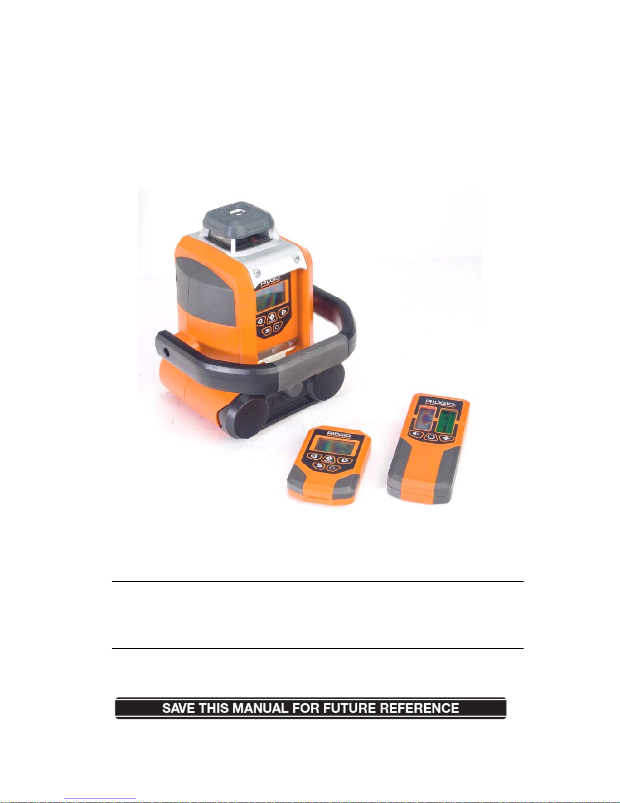
Green Auto Leveling Rotary Laser Level
GRL9202
WARNING:
To reduce the risk of injury, the user must read and understand the operator’s manual
before using this product.
Thank you for buying a RIDGID product.
Page 2

TABLE OF CONTENTS
General Safety Instruction
Safety Symbols
Damage Prevention and Information Messages
Safety Precautions for Lasers and Operations
Electricity Safety
Service Safety
FCC Statement
Unpacking and Checking Contents
Unpacking
List of Contents
Getting to Know Your Green Auto Leveling Rotary Laser Level
Main Parts
Keyboard Functions
Technical Specifications
Operation
To Install / Change Batteries
To Connect AC/DC Adapter to the Green Auto Leveling Rotary Laser Level
Turn ON/OFF the Green Auto Leveling Rotary Laser Level
Choose the Working Mode
Axis Drive Error
Remote Control
Green Laser Detector
Detector Mounting Base
Wall mounting Base
Surveyor’s tripod
Leveling rod
Application
Maintaining Your Green Auto Leveling Rotary Laser Level
Accuracy Checking and Calibration
Troubleshooting
Warranty
Page 3

GENERAL SAFETY INSTRUCTIONS
The purpose of safety symbols is to attract your attention to possible dangers. The
safety symbols and the explanations with them deserve your careful attention and
understanding. The symbol warnings DO NOT, by themselves, eliminate any danger.
The instructions and warnings they give are no substitutes for proper accident
prevention measures.
Safety Symbols
SAFETY ALERT SYMBOL: Indicates DANGER, WARNING, OR CAUTION;
may be used in conjunction with other symbols or pictographs.
DANGER: Failure to obey this safety warning WILL result in death or serious
injury to you or to others. Always follow the safety precautions to reduce the risk of fire,
electric shock, and personal injury.
WARNING: Failure to obey this safety warning CAN result in death or serious
injury to you or to others. Always follow the safety precautions to reduce the risk of fire,
electric shock, and personal injury.
CAUTION: Failure to obey this safety warning MAY result in personal injury to
you or to others or property damage. Always follow the safety precautions to reduce
the risk of fire, electric shock, and personal injury.
Damage Prevention and Information Messages
These inform user of important information and/or instructions that could lead to
equipment or other property damage if not followed. Each message is preceded by
the word “NOTE:” as in the example below:
NOTE: Equipment and/or property damage may result if these instructions are not
followed.
WARNING: Be sure to read and understand all safety instructions in this manual,
including all safety alert symbols such as “DANGER,” “WARNING,” and “CAUTION,”
before using this Green Auto Leveling Rotary Laser Level. Failure to follow all
Page 4

instructions listed below may result in electric shock, fire, and/or serious personal
injury.
Safety Precautions for Lasers and operations
DANGER: DO NOT OPERATE the leveling rod during storms or near high
voltage, if the leveling rod were to fall and contact high voltage it will result in serious
electric shock and/or bodily injury.
WARNING: Use of controls, adjustments, or performance of procedures other
than those specified in this manual may result in hazardous radiation exposure.
WARNING: The use of optical instruments such as, but not limited to,
telescopes or transits to view the laser beam will increase eye hazard.
CAUTION: Do not attempt to modify the performance of the level in any way.
This may result in a dangerous exposure to laser radiation.
WARNING:
Batteries can explode or leak, causing injury or fire. To reduce this
risk, always follow all instructions and warning on the battery label and package.
CAUTION: The following labels are on your level. They indicate the location
from which the green rotary laser level emits the laser light. Be aware of the laser light
location when using the level. Always make sure that any bystanders in the vicinity of
use are made aware of the dangers of looking directly into the laser.
YWKRC9202
YWKGRL9202
Page 5

WARNING: Laser radiation. AVOID DIRECT EYE EXPOSURE. Class a Ⅲ
Laser Product!
• Do not remove or deface any product labels.
• Avoid direct eye exposure. The laser beam can cause flash blindness.
• Never direct the laser light emitted from this level towards any person for any
reason.
• Do not place the level in a position that may cause anyone to stare at the laser
beam, whether intentionally or unintentionally.
• Do not use on surfaces that have shiny, reflective surfaces such as sheet steel.
The shiny surface could reflect the beam back at the operator.
• Always turn the green rotary laser level off when it is not in use. Leaving the level
on increases the risk of someone inadvertently staring into the laser beam.
• Do not operate the green rotary laser level around children or allow children to
operate the tool.
• Always keep this green rotary laser level, batteries and the accessories out of the
reach of children. They are not toys.
• Do not operate the green rotary laser level in combustible areas, such as in the
presence of flammable liquids, gases, or dust.
• Always use only accessories that are designed for use with this product. Use of
accessories that have been designed for use with other laser tools could result in
serious injury.
• Do not attempt to modify the performance of this laser level in any way. This may
result in a dangerous exposure to laser radiation.
• Always check to be sure that the green rotary laser level is securely mounted on
the base when using any of the base plates. Damage to the tool and/or serious
injury to the user could result if the level falls.
• Do not use the laser enhancing glasses as safety goggles. The laser enhancing
Page 6

glasses are intended to improve visibility of the laser beam, but they do not
protect against laser radiation or injuries to the eyes.
• Do not use the laser enhancing glasses as sun glasses or in traffic. The laser
enhancing glasses do not afford complete UV protection and can reduce color
perception.
• Do not use this green rotary laser level for any purpose other than those outlined
in this manual. This could result in serious injury.
• For further information regarding lasers, refer to ANSI-Z136.1, the Standard for
the Safe Use of Lasers, available from the Laser Institute of America (407)
380-1553.
• Do not short any battery terminals.
• Do not attempt to recharge alkaline batteries.
• Do not mix old and new batteries. Replace all of them at the same time with new
batteries of the same brand and type.
• Always dispose of the used batteries according to your local ordinance; do not
incinerate the batteries.
• Keep batteries out of reach of children.
• Remove batteries if the device will not be used for several months.
Electricity Safety
• Before using the power adapter, be sure that the outlet voltage supplied is same
as the voltage marked on the level’s power adapter.
• Do not expose the power adapter to rain or wet conditions. Water entering the
adapter will increase the risk of electric shock.
• Always use an outdoor extension cord marked “W-A” or “W” when operating the
power adapter outside. These cords are rated for outdoor use and reduce the risk
of electric shock.
CAUTION: To reduce the risk of electric shock, use the tool only in dry location.
Page 7

Service Safety
Do not attempt to repair or disassemble the Green Auto Leveling Rotary Laser Level.
If unqualified persons attempt to repair this product, serious injury may occur. Any
repair required on this laser tool should be performed only by authorized service
personnel.
FCC Statement
FCC STATEMENT
1. This device complies with Part 15 of the FCC Rules. Operation is subject to the
following two conditions:
(1) This device may not cause harmful interference.
(2) This device must accept any interference received, including interference that may
cause undesired operation.
2. Changes or modifications not expressly approved by the party responsible for
compliance could void the user's authority to operate the equipment.
NOTE: This equipment has been tested and found to comply with the limits for a Class B
digital device, pursuant to Part 15 of the FCC Rules. These limits are designed to provide
reasonable protection against harmful interference in a residential installation.
This equipment generates uses and can radiate radio frequency energy and, if not
installed and used in accordance with the instructions, may cause harmful interference to
radio communications. However, there is no guarantee that interference will not occur in a
particular installation. If this equipment does cause harmful interference to radio or
television reception, which can be determined by turning the equipment off and on, the
user is encouraged to try to correct the interference by one or more of the following
measures:
Reorient or relocate the receiving antenna.
Increase the separation between the equipment and receiver.
Connect the equipment into an outlet on a circuit different from that to which the receiver
is connected.
Page 8

Consult the dealer or an experienced radio/TV technician for help.
UNP ACKING AND CHECKING CONTENTS
The Green Auto Leveling Rotary Laser Level level kit comes in one box. Do not
discard any packing materials until all of the contents are accounted for.
Separate all the parts from the packing materials. Refer to the “List of Contents” and
Fig. 1a to Fig. 1c to make certain that all of the items are accounted for before
discarding any packing material. Call the RIDGID Service Center if any parts are
damaged or missing.
List of Contents
PART NAME QUANTITY
Green Auto Leveling Rotary Laser Level 1
Remote control 1
Green laser detector 1
AC/DC adapter 1
Wall mounting base 1
Detector mounting base 1
Green laser enhancing glasses 1
Magnetic laser target 1
Batteries for green rotary laser level 4
Batteries for remote control 2
Battery for green laser detector 1
Surveyor’s tripod 1
Leveling rod 1
Page 9
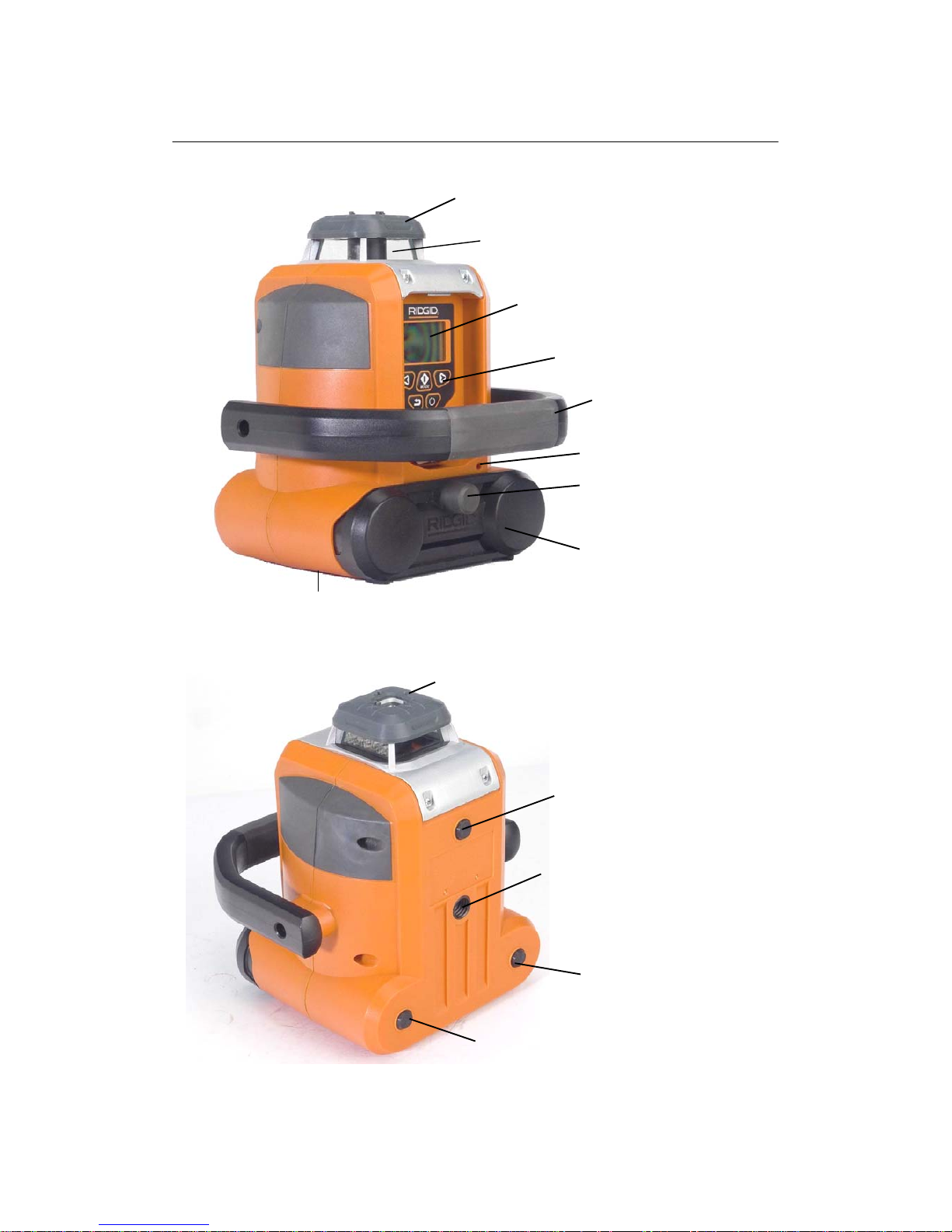
GETTING TO KNOW YOUR GREEN AUTO LEVELING ROTARY LASER LEVEL
Laser aperture
Protective cover
LCD panel
Keypad
Handle
Battery compartment
6V AC/DC Adapter
Battery cover knob
5/8” tripod screw (inside
the base
)
Fig. 1a
Top mounted sight
5/8” tripod screw
Rubber foot
Rubber foot
Rubber foot
Fig. 1b
Page 10
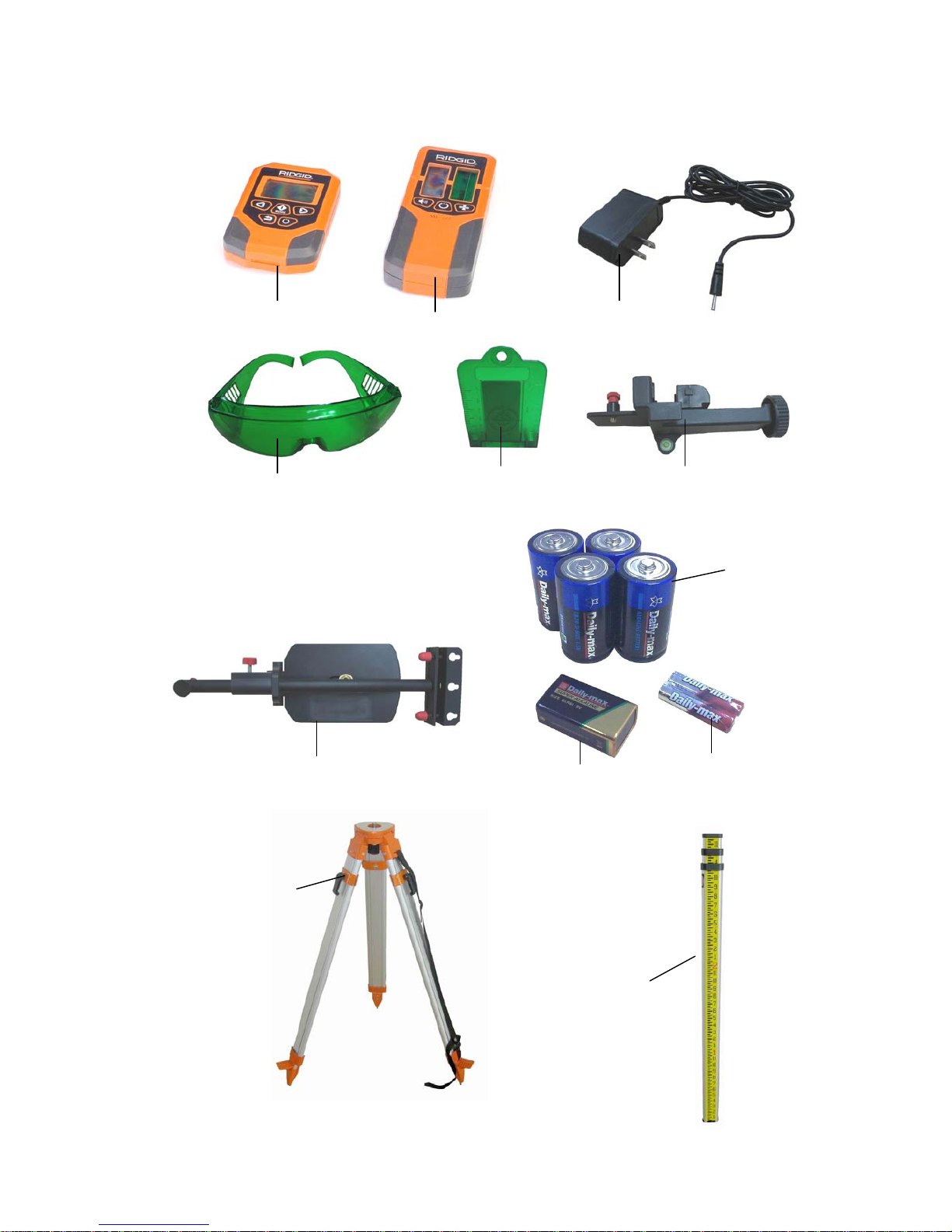
Batteries for
rotary laser
Batteries for
remote control
Batteries for
laser detector
Wall mounting base
Leveling rod
Surveyor’s
tripod
AC/DC adapter
Green laser
enhancing glasses
Magnetic laser
tar
g
et
Detector mounting base
Remote control
Green laser detector
Fig. 1c
Page 11

Protective cover
Protects the laser from dirt, water droplets and accidental damage.
Laser aperture
Laser is emitted from this aperture. AVOID direct eye exposure to the laser beam.
LCD panel
Large panel with blue backlight clearly displays the working mode and status.
Keypad (Fig. 2)
Keypad functions:
1. ON/OFF: press to turn on the level, press again to turn it off.
2. Return - return to the main menu from the submenu
3. Mode – choose among different working modes; enter the submenu
4. Left arrow – moves the cursor in the menu; moves the laser dot or chalk line
in the counter-clockwise direction.
5. Right arrow – moves the cursor in the menu; moves the laser dot or chalk line
in the clockwise direction.
Handle
Overmold handle for secure and comfortable transport.
6V AC/DC Adapter receptacle
For connection to the AC/DC adapter.
Battery cover knob
1
2
3 4 5
Fig. 2
Page 12

Turn to lock/unlock the battery cover.
Battery compartment
For 4 alkaline LR20 D batteries.
5/8” tripod screws
There are two 5/8” tripod screws: one is inside the bottom base, the other is inside the
side base. They are used to connect the level to the surveyor’s tripod or to the wall
mounting base.
Top mounted sight
To orient the level to your target, and to locate the high and low points within the arc.
Rubber feet
The rubber feet keep the level stable on the working base.
Remote control
For remote operation within a range of 133 feet.
Green laser detector
Asists the detection of the green laser line position within a maximum range of
330 feet.
AC/DC adapter
The level can be powered with the AC/DC adapter for prolonged operation.
Laser enhancing glasses
Made of laser light enhancing material, the glasses is improve the visibility of the
tool’s laser line.
WARNING: These glasses will not protect your eyes from damage that could result
from looking directly at the laser projection.
Magnetic laser target
The laser target helps to improve the visibility of the green laser lines.
When the surrounding light is too bright, the laser line may be difficult to observe.
Surveyor’s tripod
Support the laser level and permits height adjustment
Leveling rod
Supports the detector mounting base and green laser detector for detailed surveys.
Page 13

Detector mounting base
Permits the laser detector to be mounted on the leveling rod or a vertical pillar.
Wall mounting base
Hang the mounted laser level can be hung from nails or screws on a wall or clamp it to
a beam.
Technical Specifications
Power supply
4 pcs 1.5V “D” batteries for green rotary-laser level
2 pcs 1.5V “AAA” battery for remote control
1 pc 9V “6LR61” battery for green laser detector
AC/DC adapter Output: 6V dc/Input: 100-240V, 50/60Hz
Laser Diode Type Green Laser Diode 522-542nm
Laser Class Class IIIa, output <5mW
Working range
Maximum 100 ft. (30m) without detector, depending
upon light conditions
Maximum 330 ft. (100m) with detector
Working range of remote
control
133 feet (40m)
Accuracy of the rotary laser ±0.1mm/m
Accuracy of the detector Fine, ±3mm; Medium, ±5mm; Coarse, ±8mm
Auto leveling range ±5°
Leveling time About 45s
Operating time Approx. 40 hours with alkaline batteries.
Optimum operating
temperature range
0-40°C
Storage temperature range -20-60°C
Protection against water IP54
Page 14
OPERATION
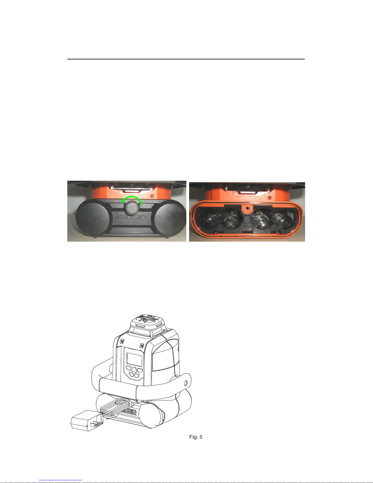
To Install /Change Batteries for the Green Auto Leveling Rotary Laser Level
This green rotary laser level uses four “D” 1.5V batteries, included.
1. Turn the battery cover knob counterclockwise to open the battery compartment
(Fig. 3).
2. Install four, new, “D” size, alkaline batteries according to the polarity indicators (+
and -) inside the battery compartment (Fig. 4).
3. Replace the battery compartment in the tool and tighten the battery cover knob
clockwise to lock it.
To Connect AC/DC Adapter to the Green Auto Leveling Rotary Laser Level
The green rotary laser level can also be powered with the AC/DC adapter.
1. Insert the connecting plug into the adapter receptacle, located in the right top of
the battery compartment (Fig. 5).
2. Plug the AC/DC adapter into the correct power outlet.
Fig. 3 Fig. 4
Page 15

Turn ON/OFF the Green Auto Leveling Rotary Laser Level
Press the power button to turn on the Green Auto Leveling Rotary Laser Level:
• The display backlight will illuminate for increased visibility.
• The backlight will turn off automatically after one minute has elapsed without
keypad operation.
• The Green Auto Leveling Rotary Laser Level will automatically self-adjust to
level in approximately 45 seconds.
• After self-leveling, the level will start operating in Rotation mode. (The default
mode is Rotation.)
Either H or V will display in the upper line, next to the battery level indicator on the
LCD when the level is turned on (Fig. 6).
H indicates that the level is positioned horizontally and will perform a leveling
measurement;
V Indicates that the level is positioned vertically and will perform a plumb
measurement.
The battery level indicator in the upper right of the display communicates the
remaining charge in the batteries in the Green Auto Leveling Rotary Laser Level (Fig.
6). Press the
button again to turn off power to the Green Auto Leveling Rotary
Laser Level.
Page 16

WARNING: When turning ON the Green Auto Leveling Rotary Laser Level, ALWAYS
be aware of protecting your eyes and the eyes of those around you from the laser.
NEVER point the laser at anyone’s face, including your own.
WORKING MODES
Press the Mode button
to enter the main menu (Fig. 7a); there are four options
on the screen: ROTATE, SWEEP, AUTO LEVEL and GRADE. Press the
or
button to move the cursor among these options. Press the button to
enter the submenu or confirm the chosen option; press the back button
to
return to the main menu.
1. ROTATEMODE (Fig. 7a)
The default ROTATE mode generates a 360º horizontal (level) or vertical (plumb)
reference, depending on the orientation of the Green Auto Leveling Rotary Laser
Level. The 360º reference laser appears on all walls of a room (horizontal) or
ceiling, floor, and opposite walls (vertical).
The ROTATE mode is automatically selected (light letters on a dark rectangle;
see Fig.7a), after the Green Auto Leveling Rotary Laser Level is turned on or use
the
button to select the ROTATE mode after another mode has been
highlighted.
With ROTATE selected (highlighted) press the
button again to enter the
sub menu to select among rotation speeds.
Fig. 7b
Fig. 7a
Page 17

− Fast (Fig.7b):, the green laser line pulses very quickly; this is useful in darker or
low light situations.
− Medium (Fig.7c): the green laser line appears to flash intermittently; this is
useful in normal indoor light condition..
− Slow (Fig.7d): low speed, the laser flashes more slowly; this is useful in bright
conditions out doors.
2. SWEEP MODE (Fig. 8a)
Instead of creating a 360º line, the Sweep (Scanning) Mode creates a shorter,
brighter laser “chalk line” that can be used for leveling or plumbing doors,
windows, fixtures, and more. You may also use this feature to keep the level from
interfering with other lasers and detectors on site.
In the main menu, press the arrow buttons
or to move the cursor
to “SWEEP” (Fig. 8a). Press the
button to enter the submenu to select the
desired configuration
Fig. 8b
Fig. 7d Fig. 7c
Fig. 8a
Page 18

− Spot mode (Fig. 8b): creates a motionless laser dot for reference, allowing the
level to be used as a straight-line laser.
− Medium (Fig. 8c): the tool produces a green laser line medium length
− Short (Fig. 8d): produces a short green laser line.
− Long (Fig. 8e): the tool sweeps a long green laser line.
Press the
button again to enter an additional submenu to change the dot
or sweep direction. The laser dot or chalk line can be moved left or right by
pressing the
or button (Fig. 8f).
3. AUTO LEVEL MODE
In the main menu, press the arrow buttons
or to move the cursor
to AUTO LEVEL (Fig. 9a). Press the
button to enter the submenu to select
the desired action. (Figs 9b, 9c, 9d).
The Auto Level Mode determines how the level responds when it is moved out of
level. The Auto level Mode can be set to ON, OFF, or Anti-Drift System (ADS).
Fig. 8e
Fig. 8d Fig. 8c
Fig. 8f
Page 19

− ON: The level will automatically re-level when it is bumped or moved.
− OFF: The level will NOT re-level if it is moved out of level, and will continue to
operate on the non-level plane. Select this option when using an adapter or
mount that allows you to tilt the level to create a diagonal laser line.
− ADS (Anti-Drift System): The level will signal to the operator that it has been
moved out of level. The laser head will stop rotating and the laser beam will
blink.
NOTE:
OFF and ADS modes are not available when the level is working in the GRADE
mode.
When setting to OFF or ADS mode, allow the level to self-level, wait until the word
“Lock” or “ADS” shows on the LCD before the mode takes effect.
4. GRADE MODE- Dual or single axis grade
The dual grade function allows more specialized site preparations, such as
road grading and paving), irrigation, trenching, landfills, slopes and
embankments, and laying pipe.
Fig. 9c
Fig. 9b
Fig. 9d
Fig. 9a
Page 20

Use the top mounted sight to orient the level to your target and to locate the
high and low points within the arc (Fig. 10).
In the main menu, press the arrow buttons
or to move the cursor
to GRADE (Fig. 11a). Press the
button to enter the submenu to select the
desired x and y axis. (Figs 11b, 11c, 11d, 11e).
In the Grade submenu, use the
or button to choose the X axis
or Y axis (Fig. 11a & Fig. 11b). Press the
button again enter the
selected axis, press the
or button to reduce or increase the
percentage of the grade (Fig. 11c to Fig. 11e). The maximum grade range for
both X axis and Y axis is 8%.
The Grade Percentage can be adjusted at any time while in this mode. The
level will not move the desired grade until after it has self-leveled; allow
ample timefor the level to react to the input provided. Refer to examples in
the illustration below to predict your results (Fig. 12a to Fig. 12d).
To exit Grade Mode, press the
button, the level will re-level.
Fig. 11c
Fig. 11a
Fig. 10
Fig. 11b
Page 21

Axis Drive Error
If the level is set up beyond its self-leveling range of ±5°, the laser head will
initially attempt to level; however, when the self-leveling limit is reached, “Over”
will appear on the LCD to communicate the axis error (Fig. 13). The laser head
will stop running or chalking, and the laser blinks.
Move the level to a more level position and allow it to re-level.
Fig. 11e
Fig. 12d
Fig. 12a
Fig. 12b
Fig. 11d
Fig. 12c
Page 22

Remote Control
Description
The remote control can operate your Green Auto Leveling Rotary Laser Level
within a maximum distance of 133 feet. Except for the power button
” , the
functions of other buttons on the remote control are the same as the buttons on
the operation panel of the level.
POWER button the remote control
Turn on/off the remote control;
Put the Green Auto Leveling Rotary Laser Level in sleep mode when the
level is turned on; it cannot turn on the rotary laser level directly if the level is
powered off.
Wake up the Green Auto Leveling Rotary Laser Level if the level is in sleep
mode.
To Install/Change Batteries for the Remote
Control
The remote control uses two “AAA” batteries.
1) Open the battery cover.
2) Insert two, new “AAA “alkaline batteries
according to the polarity indicators (+ and -)
in the battery compartment (Fig. 14). Be
sure that the polarity is correct!
Fig. 13
Fig. 14
Page 23

3) Close the cover and lock it securely in place.
Turn On the Remote Control
The remote control and the Green Auto Leveling Rotary Laser Level have a
duplex communication. To operate the remote control, press the
button to
turn it on; the display on the remote control will synchronize the display on the
Green Auto Leveling Rotary Laser Level
NOTE: If the control distance exceeds the maximum range, or if the Green Auto
Leveling Rotary Laser Level is powered off when the remote control is turned on,
“Link Lost” will appear in remote control display.
Put the Green Auto Leveling Rotary Laser Level in Sleep Mode
Press the
button on the remote control again to turn off the remote control;
it will place the level in sleep mode. The “Sleep” will display on the Rotary Laser
Level and the display backlights will flash once every two seconds to remind you
that you can “wake” the level with the remote control within two hours. After two
hours in “sleep” mode, the level will automatically shut off completely, and the
remote control cannot operate the level. If the remote control is not operated in 5
minutes, the remote control will turn off automatically.
Wake Up the Green Auto Leveling Rotary Laser Level
To wake up the Green Auto Leveling Rotary Laser Level, press the
button
on the remote control; it will activate the level and turn on the remote control.
Green Laser Detector
Description (Fig. 15 & Fig. 16)
Perfect for use in outdoor conditions, where sunlight and distance may make
locating the beam more difficult, the green laser detector aids in locating and
targeting a visible or invisible beam emitted by the Green Auto Leveling Rotary
Laser Level within a maximum range of 330 feet, It cannot detect a red-laser line.
Page 24

1. Beam receiver window: receives the green laser signals.
2. LCD: indicates the detection result and the position of the laser line.
3. Power ON/OFF button: turns the detector on/off.
Page 25

4. Buzzer ON/OFF button: turns the buzzer on/off.
5. Coarse/Fine detection button: coarsely detects the laser position or accurately
detects the laser position.
6. Lineation arrow: helps in marking a target line.
7. Lineation slot: helps in marking a target line
8. Distance indicator: shows that the lineation slot is 2 inches (50mm) to the top of
the detector.
9. 1/4’ Mounting hole: for installation on the mounting base.
10. Battery compartment: for holding a “6LR61” 9V battery
To Change/Install Battery for the Detector
1. Open the battery compartment cover.
2. Install one “6LR61” 9V battery (Fig. 17). Make sure the polarity (+/-) is
correct!
3. Close the battery compartment cover.
Locating the Green Laser Line with the Detector
NOTE: Always keep the instrument stable and level when detecting.
1. Press the
button to turn the detector on. The LCD symbols will
Fig. 17
Page 26

momentarily flash and the “coarse” indicator symbol will remain lit and the
audio signal will be on (Fig. 18a).
2. Expose the beam receive window of the laser detector towards the direction
of the rotating laser.
3. Slowly move the laser detector in an upward and downward direction until the
LCD beam indicator arrows appear and/or a pulsing audio signal is heard.
Use the coarse/fine detection button
to choose the beam resolution.
Coarse setting: used for approximating level or for initial location of the
center level point (Fig. 18a)
Medium setting: used for greater accuracy (Fig. 18b)
Fine setting: used for the most accurate pinpointing of level (Fig. 18c).
4. Move the detector upward when the low beam indicator arrow is lit (Fig. 19a).
Move the detector downward when the high beam indicator arrow is lit (Fig.
19b). When the beam is level, the level beam indicator line will be lit and a
solid audio tone will be heard (Fig. 19c).
5. Mark this position with a pencil through either side of the lineation slot.
If the detector is not struck by a laser beam after 3-4 minutes, the detector will
automatically shut itself off to preserve battery life. Turn it back on using the
power ON/OFF button.
Fig. 18a Fig. 18b Fig. 18c
Page 27

Detector Mounting Base
Description
1. Tightening knob: to securely attach the detector to a vertical pillar.
2. Release button: located on the both sides of the quick clamp. Push the buttons to
slide the quick clamp.
3. Quick clamp: slide to quickly clamp or unclamp.
Fig. 19a Fig. 19b Fig. 19c
Fig. 20
Tightening
knob
Quick
clamp
Release
button
1/4” mounting
thread screw
Round vial
Page 28

4. 1/4” mounting thread screw: Used to mount the detector.
5. Round vial: indicates whether the base is vertical and level.
Using the Detector Mounting Base
With the detector mounting base, the detector can be secured to a vertical pillar with
flat sides at 90° angles.. The maximum width the base can accommodate is 3.7”.
1. Inert the 1/4” mounting thread screw into the 1/4” mounting hole at the back of the
detector; tighten the screw to securely attach the detector (Fig. 21).
2. Press the two release buttons at the same time to slide the quick clamp and fit it
onto the vertical pillar (Fig. 22)
Fig. 21
Page 29

Wall mounting base
Description (Fig. 23)
1. Trough with 1/2” width and 1-1/8” depth - Attaches the wall-mounting base to
horizontal studs in a wall.
2. Lock screw - Secures the wall-mounting base to the stud.
3. Mounting hole - Used for hanging the wall-mounting base from a nail or screw on
a wall.
4. Pole with Inch scale: Refer to The scales when adjusting the platform up and
down.
5. Securing screw- Secures the platform to the pole.
6. Platform pivots – For easy storage of the wall mounting-base assembly.
7. Platform – Supports the Green Auto Leveling Rotary Laser Level.
Trough
Mounting hole
Fig. 23
Lock screw
Pole with Inch scale
Securing screw
Platform pivots
Platform
5/8’’ mounting
thread screw
Balance screw
Page 30

8. 5/8’’ mounting thread screw – Attaches the Green Auto Leveling Rotary Laser
Level to the base.
9. Balance screw – Adjusts the balance of the base.
Using the Wall Mounting Base
The wall mounting base can be hung from nails or screws on a wall or clamped onto a
beam. By using the wall mounting base, you can easily adjust the height and direction
of the laser to your reference object.
Hang from Nails or Screws:
The base has three mounting holes for secure attachment. Always use three screws
or nails, and make sure that these screws or nails are securely in place in the wall.
Clamp onto a Horizontal Stud
The base can only be attached to a level, horizontal stud; do not try to attach to a
vertical stud.
1. Turn the two lock screws counterclockwise (Fig. 24). Attach the wall mounting
base to a level stud, making sure that the stud is fully inserted into the trough.
2. Turn the two lock screws clockwise to secure the clamp.
3. Adjust the balance screw until the rubber support touches the wall. Ensure that the
platform is approximately level (Fig. 25).
Fig. 24
Page 31

Mount the Green Auto Leveling Rotary Laser Level on the Wall Mounting Base
1. Align the 5/8” screw on the platform with the screw hole in the bottom base or side
base of the tool.
2. Adjust the direction of the tool to your reference object.
3. Turn the screw clockwise to secure the tool on the base.
CAUTION! Whenever using the wall mounting base to secure the Green Auto
Leveling Rotary Laser Level on a stud, be sure to place the tool on the base
carefully, securing it with your hands at all times. Once you are certain that the
tool is attached firmly on the base with the screw, and the base is fastened on the
stud, you can safely remove your hands.
Adjust the Height of the Green Auto Leveling Rotary Laser Level
1. Support the base of the platform with one hand to hold the tool.
2. Turn the securing screw counterclockwise to loosen it.
3. Adjust the height of the platform to the desired position.
The platform height is
adjustable up to 11 inches.
4. Tighten the secure screw clockwise to fix the platform firmly.
Fig. 25
Page 32

Surveyor’s tripod
Description (Fig. 26)
1. 5/8’’ mounting screw – attaches the Green Auto Leveling Rotary Laser Level to
the tripod
2. Platform- supports the Green Auto Leveling Rotary Laser Level.
3. Lock lever- locks/unlocks the extension of the leg.
4. Belt- for convenient carrying or securing when not in use.
5. Leg- provides firm support.
6. Sharp foot- for stably stand in the working field
7. Pedal- step in the pedals to push the sharp feet into the ground.
5/8’’ mounting screw
Belt
Leg
Sharp foot
Mounting screw knob
Platform
Lock lever
Sharp foot
Pedal
Pedal
Fig. 26
Page 33

Using the Surveyor’s tripod
1. Expand the three legs of the tripod to a stable position; make sure the platform is
close to horizontal.
2. Step on the pedals to push the sharp feet into the ground.
3. Place the Green Auto Leveling Rotary Laser Level on the tripod; holding it in place
with your hand, adjust the direction of the tool to your reference object.
4. While holding the Green Auto Leveling Rotary Laser Level in place with your hand,
align the 5/8” mounting screw in the platform with the screw hole in the bottom
base or side base of the tool.
5. Continuing to hold the Green Auto Leveling Rotary Laser Level in place with your
hand, turn the knob of the mounting screw clockwise to secure the Green Auto
Leveling Rotary Laser Level the tripod platform.
6. Open the three lock levers to unlock the leg extension, adjust the height of the
tripod to your reference.
7. Close the lock levers to lock the leg extension securely. Now you are ready to start
the work.
Leveling rod
This leveling rod can be extended to a maximum of 8 feet. When not in use, it can be
retracted to a length of 3 feet and 2 3/8 inches for storage.
Scales are printed on both surfaces: on one surface, the scales are in increments of
0.25-inch; on the reverse surface, the scales are in increments of 0.24 inch.
To extend the leveling rod, pull the components up.; to retract the, locate and press
each release button (Fig. 27) to unlock the extension and permit the rod to be
retracted.
Page 34

DANGER: DO NOT OPERATE the leveling rod during storms or near high voltage,
leveling rod falling or touching to the high voltage will result in serious electric shock
and/or bodily injury.
APPLICATION
Your Green Auto Leveling Rotary Laser Level is a highly versatile tool. Use it for the
following applications, among others:
Outdoor Site Preparation, Grading & Excavating, Batter boards and Foundations,
Masonry Work, Setting Concrete Forms, Marking elevation, Paving Roads, Checking
Depth of Trenches, Landscaping, Fencing.
Indoor Drop Ceiling Installation, Floors, cabinets & Shelves, Carpentry, Decks &
Patios, Tile Work, Partitions, Remodeling, Doors & Windows.
Mark the Height for Foundation Pit
1. Attach the Green Auto Leveling Rotary Laser Level to the surveyor’s tripod, allow
the level to self-level.
2. Use the Detector and Leveling Rod to read the height of the level based on the
height datum.
3. Calculate the height difference of the level to the specified position. Set the leveling
rod and mark it according to the calculation (Fig. 28).
Release knob
Fig. 27
Page 35

Drop Ceiling Applications
1. Attach the wall mounting base to the wall with screws or nails or clamp onto a
horizontal stud. make sure the hanging trough of the base approximate to the level
of ceiling grid.
2. Secure the Green Auto Leveling Rotary Laser Level on the wall mounting base;
adjust the balance screw to ensure that the platform is approximately level.
3. Turn on the level; allow the laser to self-level.
4. Raise or lower the laser on the Wall Mounting Base until the rotating beam is at
the same level as the perimeter ceiling grid. Use the line created by the laser as a
reference to attach the perimeter grid to the wall.
5. Attach the magnetic laser target to the ceiling trim being installed. Adjust the
height of the trim until the laser beam strikes the target, as Fig. 29 shown.
Page 36

MAINTENANCE
This Green Auto Leveling Rotary Laser Level has been designed to be a
low-maintenance tool.
However, in order to maintain its performance, you must always follow these simple
directions.
Always handle the level with care. Treat it as the fine optical device it is and as
you would treat a camera or binoculars.
Avoid exposing the level to shock, continuous vibration, or extreme hot or cold
temperatures.
Always store the level indoors. When not in use, always store the tool in its
protective case.
After you have finished using the level, always make sure that the level has been
turned off.
Always keep the level free of dust and liquids. If needed, only use a soft cloth or
cotton swab and glass cleaner to clean the laser emitting window.
Always wipe clean and thoroughly dry the level after each use.
Check the batteries regularly to avoid deterioration.
Always remove the batteries from the level, remote control and detector if they
are not going to be used for an extended period of time.
Always replace the batteries when the battery icon shows empty.
Page 37

Do not disassemble this green rotary laser level. This will not only void the
warranty, but could expose the user to hazardous radiation exposure.
Do not attempt to change any part of the laser lens.
Tool service must be performed only by an authorized service center. Service or
maintenance performed by unqualified personnel could result in risk of injury.
CHECKING ACCURACY AND CALIBRATION
This Green Auto Leveling Rotary Laser Level is a sealed level and is calibrated to
precise accuracies at the factory. However, a calibration check is recommended
before the initial use of your laser, and then periodically from that point forward.
Be sure to allow enough time (up to 60 seconds) for the level to completely
self-level before each check.
CAUTION: When performing a calibration, always use the remote control to
adjust the level, pressing buttons on the level will bring small movements to the
accurate electronic vials inside and result in incorrect calibration.
Checking Accuracy -X Axis
1. Mount the Green Auto Leveling Rotary Laser Level on a tripod or to a level,
sturdy surface and place it approximately 100 feet (30m) away from a wall.
Face the display toward you and “X+” to the target wall (Fig. 30 and Fig. 31).
Page 38

2. Press the
”button to turn on the Green Auto Leveling Rotary Laser Level
and allow the tool to self-level. Draw a plumb line on the wall; mark the
intersection of the plumb line and the laser beam as “A”.
3. Loosen the Green Auto Leveling Rotary Laser Level from the tripod and
rotate the Green Auto Leveling Rotary Laser Level 180°. Ensure that the
height of the tripod does not change, as this will affect the results. Secure the
Green Auto Leveling Rotary Laser (Fig. 32).
Fig. 31
Fig. 30
Page 39

4. Allow the tool to self-level. Mark the intersection of the plumb line and the
laser beam as “B”. No adjustment is necessary if the vertical difference
between A and B is less than 1/4” (6.5mm)
Repeat the above steps to ensure a correct reading. If the distance is greater
than 1/4”, you will need to calibrate the X axis.
Calibration- X Axis
1. Keeping the Green Auto Leveling Rotary Laser Level in its current position,
turn the power off; turn the display toward you, and make X+ facing the target
(i.e. wall, detector), as shown in Fig. 30 and Fig. 31..
2. Turn on the level and remote control, press the “
” and “ ” button at
the same time to activate calibration mode.(Fig. 33a)
Fig. 32
Page 40

3. Use the
button to select “Xad” (Fig. 33b); press the ”button to
access the X axis for calibration (Fig. 33c).
WARNING: A wrong choice of other options may result in error. Press the back
button
to exit and re-choose the correct option.
4. You must raise or lower the beam to center it between points A and B on the
target. The level will react to “+” and “-“ input within the X+ quadrant.
If A is above B, press the
button on the remote control to move the
laser beam downward.
If A is below B, press the
button on the remote control to move the
laser beam upward.
NOTE: The parameters displayed on the display on the Green Auto Leveling
Rotary Laser Level can be ignored when performing the adjustment.
6. Press
button to save the calibration; press the button
repeatedly to exit from calibration mode.
7. Now repeat the X axis check to insure that you have made the correct
Fig. 33c
Fig. 33a
Fig. 33b
Page 41

calibration.
Checking Accuracy and Calibration- Y Axis
To check the Y axis, mount the Green Auto Leveling Rotary Laser Level l on a
tripod and place it approximately 100 feet (30m) away from the wall, with the Y+
quadrant facing the wall (Fig. 31); follow steps 2 through 4 of “Checking
Accuracy -X Axis”. Calibration as in “Calibration- X Axis”, choosing the “Yad” to
calibrate and adjusting “+” and “-“input as necessary within the Y+ quadrant (Fig.
34a and Fig. 34b).
Checking Accuracy - Z Axis
1. To check the Z axis, place the Green Auto Leveling Rotary Laser Level on its
back (display facing up), 100 feet (30m) from a wall on a flat, level surface
(Fig. 35).
2. Hang a plumb line down the wall at least 8 feet long.
3. Press the
button to turn on the level, allow the Green Auto Leveling
Rotary Laser Level l to self-level. If necessary, adjust the rotation speed to
easily view the laser beam on the wall.
4. Orient the Green Auto Leveling Rotary Laser Level parallel to the wall and
attempt to align the laser with your plumb line. If the laser line does not align
with the plumb line, then calibration is necessary.
Fig. 34b
Fig. 34a
Page 42

Calibration-Z Axis
Keep the Green Auto Leveling Rotary Laser Level in the current position, power
off the level.
1. Turn on the level and the remote control;. Press the
and
button on the remote control at the same time to enter calibration mode (Fig.
33a).
2. Use
button to select “Zad” (Fig. 36a); press the button to access
the Z axis for calibration (Fig. 36b).
3. Press the
button on the remote control to rotate the laser beam
counterclockwise, or press the
button on the remote control to rotate
the laser beam clockwise into alignment with your plumb line. For example,
Fig. 36b
Fig. 35
Fig. 36a
Page 43

the laser beam must rotate counterclockwise to align with the plumb line, so
you need to press the
button.
4. Press the
button to save the calibration, press button repeatedly
to exit from calibration mode.
5. Now repeat the Z axis checking to insure you have made the correct
calibration.
TROUBLESHOOTING
PROBLEM POSSIBLE CAUTION SOLUTION
Laser dot/line
projected is
weak, hard to
see
1. Battery is depleted.
2. The tool is out of the
operating temperature
range.
3. The tool is too far from
the target.
4. Working condition is too
bright.
1. Replace with new batteries or
run it with AC/DC adapter.
2. Make sure that the tool
operating temperature is
within 32°F to 104°F.
3. Move the tool closer to the
target.
4. Use green laser-enhancing
glasses and green-laser
detector to locate the laser
position.
Laser dot/line is
not projected
1. The tool is put in sleep
mode.
2. The tool is performing
leveling adjustment
automatically.
3. The tool suffers a sudden
shock
4. The tool is out of the
operating temperature
range.
1. Wake up the tool with the
remote control or turn off and
on again.
2. Wait until the Auto leveling
adjustment is finished.
3. Wait until the tool re-levels
automatically.
4. Make sure the tool operating
temperature is within 32°F to
104°F.
Page 44

The rotary laser
stops spinning
and the laser dot
winks
1. The tool is out of leveling
range.
2. The slope setting in slope
mode is out of the
adjustable range of the
tool.
3. The tool is set ADS in
Auto Level mode and
suffers a sudden shock in
working.
1. Adjust to make sure the
support for the tool is close to
horizontal.
2. Adjust to make sure the
support for the tool is close to
horizontal or reduce the slope
setting.
3. Change the Auto Level mode
to OFF first, recheck the
reference and set to ADS
again.
Laser dot/line
projected is not
level
1. The tool is in slope mode.
2. The tool is set to OFF in
Auto Level mode; it will
NOT re-level if the tool
was moved.
1. Press the Return button to go
back to the rotation mode; the
tool will re-level.
2. Set the tool to ON in Auto
Level Mode, it will re-level.
Detector cannot
find the laser
1. It detects a red laser line.
2. the detector is out of its
working range
3. Battery is depleted.
1. This detector can only detect
green pulse laser.
2. Make sure the distance
between tool and detector
does not exceed 330 feet.
3. Replace with a new battery.
The remote
control cannot
operate the tool,
and LCD shows
“LINK LOST”
1. The tool is shut off
2. The remote control is out
of its working range
1. Press the ON/OFF button to
turn on the tool first, then turn
on the remote control to
operate it.
2. Make sure the distance
between tool and remote
control does not exceed 133
feet.
The tool emits
continuous
sound inside.
The adjusting mechanical
inside is working
automatically.
This is normal.
 Loading...