

Page 1
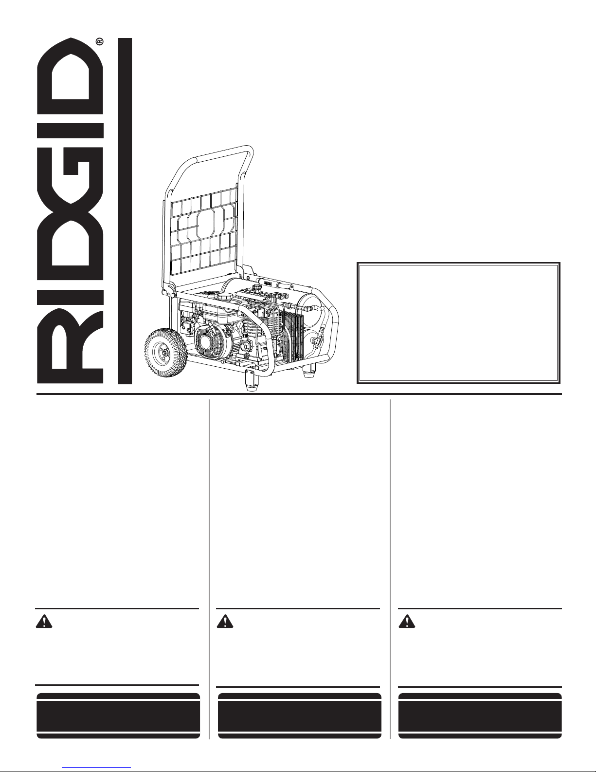
OPERATOR’S MANUAL
MANUEL D’UTILISATION
MANUAL DEL OPERADOR
8 GALLON PORTABLE AIR COMPRESSOR
COMPRESSEUR D’AIR PORTABLE
DE 30,3 LITRES (8 GALLONS)
COMPRESOR DE AIRE PORTÁTIL
DE 30,3 LITROS (8 GALONES)
GP80150RT
To register your RIDGID product, please
visit: http://register.RIDGID.com
Pour enregistrer votre produit de
RIDGID, s’il vous plaît la visite :
http://register.RIDGID.com
INCLUDES: Air Compressor, Feet, Wheels,
Mounting Hardware, Engine Oil, Pump Oil,
Operator’s Manual
TABLE OF CONTENTS
****************
General Safety Rules .......................3-4
Specific Safety Rules .........................5
Symbols ..............................................6
Glossary of Terms ............................... 7
Special Terms ..................................... 7
Features .............................................. 8
Assembly .........................................8-9
Operation .....................................10-16
Maintenance ................................17-19
Troubleshooting ...........................20-21
Warranty ...........................................22
Illustrations ..................................23-29
Parts Ordering / Service ..... Back Page
WARNING:
To reduce the risk of injury, the
user must read and understand
the operator’s manual before
using this product.
INCLUT : Compresseur d’air, pieds,
roues, quincaillerie de montage, huile
moteur, huile pompe, manuel d’utilisation
TABLE DES MATIÈRES
****************
Règles de sécurité générales ............. 3-4
Règles de sécurité particulières ............. 5
Symboles ...............................................6
Glossaire ................................................7
Termes spécialisés .................................7
Caractéristiques .....................................8
Assemblage........................................ 8-9
Utilisation ......................................... 9-16
Entretien ......................................... 17-20
Dépannage ..................................... 20-21
Garantie ................................................22
Illustrations ..................................... 23-29
Commande de pièces /
réparation ............................. Page arrière
AVERTISSEMENT :
Pour réduire les risques de
blessures, l’utilisateur doit lire
et veiller à bien comprendre
le manuel d’utilisation avant
d’utiliser ce produit.
Para registrar su producto
de RIDGID, por favor visita:
http://register.RIDGID.com
INCLUYE: Compresor de aire, patas, ruedas,
piezas de montaje, aceite para motor, aceite
de bomba, manual del operador
ÍNDICE DE CONTENIDO
****************
Reglas de seguridad generales .......... 3-4
Reglas de seguridad específicas ........... 5
Símbolos ................................................ 6
Glosario de términos .............................. 7
Términos especiales ..............................7
Características ....................................... 8
Armado ............................................... 8-9
Funcionamiento................................ 9-16
Mantenimiento ............................... 17-20
Solución de problemas .................. 20-21
Garantía ................................................22
Ilustraciones ................................... 23-29
Pedidos de piezas /
servicio .............................. Pág. posterior
ADVERTENCIA:
Para reducir el riesgo de
lesiones, el usuario debe leer
y comprender el manual del
operador antes de usar este
producto.
SAVE THIS MANUAL FOR
FUTURE REFERENCE
CONSERVER CE MANUEL
POUR FUTURE RÉFÉRENCE
GUARDE ESTE MANUAL
PARA FUTURAS CONSULTAS
Page 2

DANGER:
This compressor/pump is not equipped and should not be used to supply breathing quality air. Additional equipment would be necessary to properly filter and purify the air to meet minimal specifications for Grade D breathing
as described in Compressed Gas Association Commodity Specification G 7.1 - 1966, OSHA 29 CFR 1910.134.
Compressed Gas Association, 4221 Walney Road, Fifth Floor, Chantilly, VA 20151-2923, (703) 788-2700,
www.cganet.com. Any such additional equipment has not been examined and no implication of proper use for
breathing air is intended or implied.
If this compressor is altered in any way, existing warranties shall be voided. RIDGID® and One World Technologies,
Inc., disclaim any liabilities whatsoever for any loss, personal injury, or damage.
DISCLAIMER OF WARRANTIES
In the event the compressor is used for the purpose of breathing air application and proper in-line safety and alarm
equipment is not simultaneously used, existing warranties shall be voided, and RIDGID® disclaims any liabilities
whatsoever for any loss, personal injury, or damage.
DANGER :
Ce compresseur / pompe n’est pas équipé et ne doit pas être utiliser pour fournir de l’air de qualité respirable. Un
équipement supplémentaire est nécessaire pour filtrer et purifier l’air conformément aux spécifications minimum
d’air respirable de qualité D G 7.1 - 1966, OSHA 29 CFR 1910. 134 de la Compressed Gas Association, 4221
Walney Road, Fifth Floor, Chantilly, VA 20151-2923, (703) 788-2700, www.cganet.com. Un tel équipement n’a pas
été examiné et nulle implacation d’utilisation propre pour l’air respirable n’est prévue ou implicite.
Si ce compresseur est modifier de quelle que manière que ce soit, les garanties en vigueur seront déclarées
nulles et non avenues. RIDGID®. et One World Technologies, Inc., déclineront toute responsabilité pour les pertes,
blessures et dommages résultant de son utilisation.
EXONÉRATION DE GARANTIES
Si ce compresseur est utilisé pour des applications d’air respirable sans un système de sécurité et d’alarme
approprié, les garanties en vigueur seront déclarées nulles et non avenues et RIDGID® déclinera toute responsabilité
pour les pertes, blessures et dommages résultant de son utilisation.
PELIGRO:
Este compresor (o bomba) no está equipado y debe evitarse utilizarlo para suministrar aire para respirar. Es necesario
equipo adicional para filtrar y purificar debidamente el aire a fin de que cumpla las especificaciones mínimas de
Grado D para respiración, según se explica en la Especificación de Productos G 7.1 - 1966 de la Asociación de
Proveedores de Equipo de Gas Comprimido (Compressed Gas Association), OSHA 29 CFR 1910.134. Compressed
Gas Association, 4221 Walney Road, Fifth Floor, Chantilly, VA 20151-2923, (703) 788-2700, www.cganet.com.
Tal equipo adicional no ha sido examinado y no debe suponerse o deducirse ninguna conclusión con respecto
al correcto uso del aire de respiración.
Si se altera de cualquier forma este compresor, quedan anuladas todas las garantías presentes. RIDGID®. y
One World Technologies, Inc., se eximen de toda responsabilidad de cualquier tipo por cualquier pérdida, lesión
corporal o daño material.
EXTENCIÓN DE RESPONSABILIDAD DE LAS GARANTÍAS
En caso de utilizarse los compresores para suministrar aire de respiración, y no utilizarse simultáneamente equipo
en línea de seguridad y alarma apropiado, se anulan todas las garantías presentes, y RIDGID® se exime de toda
responsabilidad de cualquier tipo por cualquier pérdida, lesión física o daño material que resulte.
2 – English
Page 3

GENERAL SAFETY RULES
WARNING:
Read and understand all instructions. Failure
to follow all instructions listed below may result
in electric shock, fire and/or carbon monoxide
poisoning which will cause death or serious
personal injury.
SAVE THESE INSTRUCTIONS
Do not overreach. Keep proper footing and balance
at all times. Proper footing and balance enables better
control of the product in unexpected situations.
Use safety equipment. Always wear eye protection.
Dust mask, nonskid safety shoes, hard hat, or hearing
protection must be used for appropriate conditions.
Do not use on a ladder or unstable support. Stable
footing on a solid surface enables better control of the
air compressor in unexpected situations.
WORK AREA
Keep your work area clean and well lit. Cluttered
benches and dark areas invite accidents. Floor must not
be slippery from wax or dust.
Do not operate air compressors in explosive atmo-
spheres, such as in the presence of flammable liquids,
gases, or dust. Air compressors create sparks which may
ignite the dust or fumes.
Keep bystanders, children, and visitors away while
operating an air compressor. Distractions can cause you
to lose control.
Operate air compressor in an open area at least 18 in.
away from any wall or object that could restrict the
flow of fresh air to ventilation openings.
PERSONAL SAFETY
Always wear eye protection with side shields marked
to comply with ANSI Z87.1 as well as hearing protection when operating this equipment.
The employer and/or user must ensure that proper
eye protection is worn. We recommend a Wide Vision
Safety Mask for use over eyeglasses or standard safety
glasses that provide protection against flying particles
both from the front and side. Always use eye protection
which is marked to comply with ANSI Z87.1.
Additional safety protection will be required in some
environments. For example, the working area may
include exposure to a noise level which can lead to hearing damage. The employer and user must ensure that any
necessary hearing protection is provided and used by the
operator and others in the work area. Some environments
will require the use of head protection equipment. When
required, the employer and user must ensure that head
protection marked to comply with ANSI Z89.1 is used.
Stay alert, watch what you are doing, and use com-
mon sense when operating the air compressor. Do
not use product while tired or under the influence of
drugs, alcohol, or medication. A moment of inattention
while operating an air compressor may result in serious
personal injury.
Dress properly. Do not wear loose clothing or jewelry.
Contain long hair. Keep your hair, clothing, and gloves
away from moving parts. Loose clothes, jewelry, or long
hair can be caught in moving parts.
AIR COMPRESSOR USE AND CARE
For outdoor use only.
Do not exceed the pressure rating of any component
in the system.
Protect material lines and air lines from damage or
puncture. Keep hose away from sharp objects, chemical
spills, oil, solvents, and wet floors.
Check hoses for weak or worn condition before each
use, making certain all connections are secure. Do not
use if defect is found. Purchase a new hose or notify a
qualified service center for examination or repair.
Release all pressures within the system slowly. Dust
and debris may be harmful.
Store idle air compressors out of the reach of children
and other untrained persons. Air compressors are dan-
gerous in the hands of untrained users.
Maintain air compressors with care. Follow mainte-
nance instructions. Properly maintained products are
easier to control.
Check for misalignment or binding of moving parts,
breakage of parts, and any other condition that may
affect the product’s operation. If damaged, have the
air compressor serviced before using. Many accidents
are caused by poorly maintained products.
Keep the exterior of the air compressor dry, clean, and
free from oil and grease. Always use a clean cloth when
cleaning. Never use brake fluids, gasoline, petroleumbased products, or any strong solvents to clean the unit.
Following this rule will reduce the risk of deterioration of
the enclosure plastic.
Keep the engine free of grass, leaves, or grease to
reduce the chance of a fire hazard.
Keep guards in place and in working order. Never oper-
ate the tool with any guard or cover removed. Make sure
all guards are operating properly before each use.
Do not operate the engine in a confined space where
dangerous carbon monoxide fumes can collect. Carbon
monoxide, a colorless, odorless, and extremely dangerous gas, can cause unconsciousness or death.
Keep the exhaust pipe free of foreign objects.
Do not operate around dry brush, twigs, cloth rags, or
other flammable materials.
3 – English
Page 4

GENERAL SAFETY RULES
Never pick up or carry a machine while the engine is
running.
Never start the machine if ice has formed in any part
of the equipment.
Always operate the machine on a level surface. If the
engine is on an incline, it could seize due to improper
lubrication (even at the maximum oil level).
Never attempt to make any adjustments while the
engine (motor) is running (except where specifically
recommended by the manufacturer).
Protective covers must always cover rotating parts
when the engine is running.
Keep cooling air intake (recoil starter area) and muffler
side of the engine at least 3 feet away from buildings,
obstructions, and other combustible objects.
Keep the engine away from flammables and other
hazardous materials.
Keep away from hot parts. The muffler and other engine
parts become very hot; use caution.
Do not touch the spark plug and ignition cable when
starting and operating the engine.
Check fuel hoses and joints for looseness and fuel
leakage before each use.
Check bolts and nuts for looseness before each use.
A loose bolt or nut may cause serious engine problems.
Always refuel outdoors. Never refuel indoors or in a
poorly ventilated area.
Never store the machine with fuel in the fuel tank
inside a building where ignition sources are present,
such as hot water and space heaters, clothes dryers,
and the like.
If the fuel tank has to be drained, do this outdoors into
a container approved for gasoline and away from all
ignition sources.
To reduce the risk of fire and burn injury, handle fuel
with care. It is highly flammable.
Do not smoke while handling fuel.
Add fuel before starting the engine. Never remove the
cap of the fuel tank or add fuel while the engine is running
or when the engine is hot.
Loosen fuel cap slowly to release pressure and to keep
fuel from escaping around the cap.
Replace all fuel tank and container caps securely.
Wipe spilled fuel from the unit. Move 30 feet away from
refueling site before starting engine.
If fuel is spilled, do not attempt to start the engine but
move the machine away from the area of spillage and
avoid creating any source of ignition until fuel vapors
have dissipated.
Never attempt to burn off spilled fuel under any
circumstances.
Before storing, allow the engine to cool.
Store fuel in a cool, well-ventilated area, safely away
from spark and/or flame-producing equipment.
Store fuel in containers specifically designed for this
purpose.
Empty fuel tank and restrain the unit from moving
before transporting in a vehicle.
Make sure minimum clearance of 3 feet is maintained
from combustible materials.
SERVICE
When servicing a product, use only recommended
or equivalent replacement parts. Follow instructions
in the Maintenance section
unauthorized parts or failure to follow Maintenance
instructions may create a risk of injury.
Service must be performed only by qualified repair
personnel. Service or maintenance performed by
unqualified personnel may result in a risk of injury.
Disconnect the spark plug wire, open drain valve to
decompress tanks and allow water to drain, and allow
air compressor to become cool to the touch before
servicing. Turn pressure regulator knob fully counter-
clockwise after shutting off air compressor.
of this manual. Use of
4 – English
Page 5

SPECIFIC SAFETY RULES
Know your air compressor. Read operator’s manual
carefully. Learn its applications and limitations, as well
as the specific potential hazards related to this product.
Following this rule will reduce the risk of electric shock,
fire, or serious injury.
Drain tanks of moisture after each day’s use. If unit will
not be used for a while, it is best to leave drain valve open
until such time as it is to be used. This will allow moisture
to completely drain out and help prevent corrosion on the
inside of tanks.
Risk of Fire or Explosion. Do not spray flammable liquid
in a confined area. Spray area must be well ventilated. Do
not smoke while spraying or spray where spark or flame
is present. Keep compressors as far from the spraying
area as possible, at least 15 feet from the spraying area
and all explosive vapors.
Risk of Bursting. Do not adjust regulator to result in
output pressure greater than marked maximum pressure
of attachment. Do not use at pressure greater than 150 psi.
Inspect tanks yearly for rust, pin holes, or other
imperfections that could cause it to become unsafe.
Never weld or drill holes in the air tanks.
Make sure the hose is free of obstructions or snags.
Entangled or snarled hoses can cause loss of balance or
footing and may become damaged.
Use the air compressor only for its intended use. Do
not alter or modify the unit from the original design
or function.
Do not sit or stand on the air compressor frame or
attempt to use the frame as a work surface.
Always be aware that misuse and improper handling of
this product can cause injury to yourself and others.
Never leave a tool unattended with the air hose
attached.
Never point any air tool toward yourself or others.
Do not operate this air compressor if it does not
contain a legible warning label.
Do not continue to use a tool or hose that leaks air or
does not function properly.
Always disconnect the air supply and remove spark
plug wire before making adjustments, servicing a
product, or when a product is not in use.
Do not attempt to pull or carry the air compressor by
the hose.
Your tool may require more air consumption than this
air compressor is capable of providing.
Always follow all safety rules recommended by the
manufacturer of your air tool, in addition to all safety
rules for the air compressor. Following this rule will
reduce the risk of serious personal injury.
Never direct a jet of compressed air toward people or
animals. Take care not to blow dust and dirt towards
yourself or others. Following this rule will reduce the risk
of serious injury.
Do not use this air compressor to spray chemicals.
Your lungs can be damaged by inhaling toxic fumes. A
respirator may be necessary in dusty environments or
when spraying paint. Do not carry while painting.
Inspect hoses periodically and, if damaged, have
repaired at your nearest Qualified Service Center.
Check damaged parts. Before further use of the air
compressor or air tool, a guard or other part that is
damaged should be carefully checked to determine
that it will operate properly and perform its intended
function. Check for alignment of moving parts, binding
of moving parts, breakage of parts, mounting, and
any other conditions that may affect its operation. A
guard or other part that is damaged should be properly
repaired or replaced by a qualified service center.
Following this rule will reduce the risk of shock, fire, or
serious injury.
Never store a tool with air connected. Storing the tool
with air connected can result in unexpected firing and
possible serious personal injury.
Protect your lungs. Wear a face or dust mask if the
operation is dusty. Following this rule will reduce the risk
of serious personal injury.
Save these instructions. Refer to them frequently and use
them to instruct others who may use this product. If you
loan someone this product, loan them these instructions
also.
5 – English
Page 6
SYMBOLS
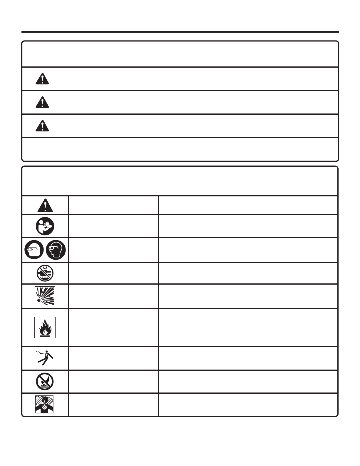
The following signal words and meanings are intended to explain the levels of risk associated with this product.
SYMBOL SIGNAL MEANING
DANGER:
WARNING:
CAUTION:
NOTICE:
Some of the following symbols may be used on this product. Please study them and learn their meaning. Proper
interpretation of these symbols will allow you to operate the product better and safer.
SYMBOL NAME
Safety Alert Indicates a potential personal injury hazard.
Read Operator’s Manual
Indicates an imminently hazardous situation, which, if not avoided, will result
in death or serious injury.
Indicates a potentially hazardous situation, which, if not avoided, could result
in death or serious injury.
Indicates a potentially hazardous situation, which, if not avoided, may result in
minor or moderate injury.
(Without Safety Alert Symbol) Indicates important information not related to an
injury hazard, such as a situation that may result in property damage.
DESIGNATION/EXPLANATION
To reduce the risk of injury, user must read and understand
operator’s manual before using this product.
Eye Protection
Wet Conditions Alert Do not expose to rain or use in damp locations.
Risk of Bursting
Risk of Fire or Explosion
Risk of Electrical Shock
Hot Surface
Risk to Breathing
Always wear eye protection with side shields marked to comply
with ANSI Z87.1.
Do not adjust regulator to result in output pressure greater than
marked maximum pressure of attachment. Do not use at pressure
greater than 150 PSI.
Do not spray flammable liquid in a confined area. Spray area must
be well ventilated. Do not smoke while spraying or spray where
spark or flame is present. Keep compressors as far from the spraying area as possible, at least 15 feet from the spraying area and
all explosive vapors.
Failure to use in dry conditions and to observe safe practices can
result in electric shock.
To reduce the risk of injury or damage, avoid contact with any hot
surface.
Air obtained directly from the air compressor should never be used
to supply air for human consumption.
6 – English
Page 7

GLOSSARY OF TERMS
Air Filter
Porous element contained within a metal or plastic housing
attached to the compressor cylinder head which removes
impurities from the intake air of the compressor.
Air Tank
Cylindrical component which contains the compressed air.
Belt Guard
Protects the operator from coming in contact with the belt
and rotating pulleys.
Cut-In Pressure
The low pressure at which the engine speed will automatically
increase to full speed.
Cut-Off Pressure
The high pressure at which the engine speed will automatically
decrease to idle speed.
NPT (National Pipe Thread)
A seal thread tape must be used to provide a leak-free seal
on pipe threaded connections.
On/Off Switch
Control which turns the air compressor on or off. The
pressure switch will not automatically start and control the
compressor unless the manual on/off switch is in the ON
( l ) position.
Pressure Regulator Knob
Regulates the outgoing pressure from the air outlet to the
tool. It is possible to increase or decrease the pressure at
the outlet by adjusting this control knob.
Pressure Unloader
Controls the speed of the compressor’s engine. The engine
runs at idle speed when the cut-off pressure in the tank is
reached and switches the engine to full speed once the
pressure drops below the cut-in pressure.
PSI (Pounds Per Square Inch)
Measurement of the pressure exerted by the force of the
air. The actual psi is measured by a pressure gauge on the
compressor.
Pump
Produces the compressed air with a reciprocating piston
contained within the cylinder.
Quick Connect Couplers
The 1/4 in. quick connect couplers allow the operator to
easily attach air hoses to the compressor.
Outlet Pressure Gauge
Displays the current line pressure. Line pressure is adjusted
by rotating the pressure regulator knob.
Safety Valve
Prevents air pressure in the air tank from rising over a
predetermined limit.
SCFM (Standard Cubic Feet Per Minute) or CFM (Cubic
Feet Per Minute)
A unit of measure of air delivery.
Tank Pressure Gauge
Indicates the pressure in the air tank.
SPECIAL TERMS
Belt Tensioner Bolt
This bolt moves the engine toward or away from the pump
to allow you to reposition or replace the drive belt.
Compressor Tank
The air compressor and 4 gallon stationary tank.
Quarter Turn Drain Valves
Quarter turn drain valves are located on tanks for easy draining of condensate to help prevent tank corrosion.
Removable Tank
The 4 gallon tank that is removable.
Unregulated Air Hose
This hose transmits the compressed air from the compressor
tank to the removable tank.
Unregulated Air Quarter Turn Ball Valve Lever
This valve opens to allow compressed air to flow from the
compressor tank to the removable tank and closes to stop
air flow from the compressor tank to the removable tank.
Unregulated Air Intake Coupler
This coupler is an air inlet only for the unregulated air hose
and is located on the removable tank.
Unregulated Air Fitting
This 1/4 in. NPT quick-connect fitting connects the unregulated air hose and is located on the compressor tank.
7 – English
Page 8
FEATURES
PRODUCT SPECIFICATIONS
Air Tank Capacity ........................................................................................................................................................... 8 gal.
Air Pressure .........................................................................................................................................................150 psi max.
Air Delivery ............................................................................................................................................. 10.2 SCFM @ 90 psi
Engine.................................................................................................................................................................. 170 cc OHC
Gauges .............................................................................................................................................................. 2 in. diameter
CALIFORNIA PROPOSITION 65
WARNING:
This product, its exhaust, and other substances that may become airborne from its use may contain chemicals,
including lead, known to the State of California to cause cancer, birth defects, or other reproductive harm. Wash
hands after handling.
ASSEMBLY
UNPACKING
This product requires assembly.
Carefully remove the tool and any accessories from the
box. All items listed in the Includes section must be
included at the time of purchase.
WARNING:
Items in this Assembly section are not assembled
to the product by the manufacturer and require
customer installation. Use of a product that may
have been improperly assembled could result in
serious personal injury.
If any parts are damaged or missing, please call
1-866-539-1710 for assistance.
WARNING:
Do not attempt to modify this product or create
accessories or attachments not recommended
for use with this product. Any such alteration
or modification is misuse and could result in a
hazardous condition leading to possible serious
personal injury.
WARNING:
To prevent accidental starting that could cause
serious personal injury, always disconnect the
engine spark plug wire from the spark plug when
assembling parts.
WARNING:
If any parts are damaged or missing do not operate
this product until the parts are replaced. Use of
this product with damaged or missing parts could
result in serious personal injury.
8 – English
Page 9

ASSEMBLY
LOOSE PARTS LIST
See Figure 1, page 23.
The following items are included with the air compressor:
Key
No. Description Qty.
1 Axle Bolt ..............................................................2
2 Spacers ...............................................................2
3 Lock Washer (18 mm) ..........................................2
4 Flat Washer (18 mm) ............................................2
5 Wheel ...................................................................2
6 Legs with Rubber Feet ........................................2
7 Nut (5 mm) ...........................................................4
8 Flat Washer (5 mm) ..............................................4
9 Lock Washer (5 mm) ............................................4
10 Screw ...................................................................4
11 Spark Plug Wrench ..............................................1
Pump Lubricant (not shown) ...............................1
Engine Lubricant (not shown) ..............................1
Operator’s Manual (not shown) ...........................1
TOOLS NEEDED
The following tools (not included) are needed for assembling
or maintaining the air compressor.
Hex Keys
Adjustable Wrench
NOTE: Do not put fuel or oil in the air compressor before
installing the legs and wheels.
Raise the front end of the air compressor, where the pump
is located, high enough to gain access to the frame bottom; securely position props underneath to support.
Position a leg over the holes on each side of the frame.
Insert each screw through a lock washer and a flat washer,
then insert the screws through the two holes in the leg
and the frame.
Install a nut over each screw on the inside of the frame
and tighten securely.
Repeat with remaining leg.
INSTALLING THE WHEELS
See Figure 3, page 24.
Locate the following items:
2 axle bolts
2 spacers
2 lock washers (18 mm)
2 flat washers (18 mm)
2 wheels
Raise the back end of the air compressor, where the
engine is located, high enough to gain access to the frame
bottom; securely position props underneath to support.
Insert a wheel spacer into the center of the wheel.
Insert axle bolt through lock washer and flat washer,
through the spacer and wheel, and then into threaded
opening on air compressor frame. Tighten axle bolt
securely.
Repeat the process on the other side to install second
wheel.
INSTALLING LEGS
See Figure 2, page 24.
Locate the following items:
2 legs with rubber feet
4 lock washers (5 mm)
4 flat washers (5 mm)
4 nuts (5 mm)
4 screws
REMOVING THE PUMP OIL LABEL
See Figure 4, page 24.
The air compressor has a label installed between the pump
oil cap and the oil fill hole. Before using the unit the first time,
remove the pump oil cap and label, then reinstall the cap.
Make sure to add oil before first use. See Adding/Checking
Pump Oil before first time operation.
9 – English
Page 10
OPERATION
DANGER:
Carbon Monoxide. Using a gas-powered air
compressor indoors CAN KILL YOU IN MINUTES.
Engine exhaust contains high levels of carbon
monoxide (CO), a poisonous gas you cannot see
or smell. If you can smell the engine exhaust, you
are breathing CO. But even if you cannot smell the
exhaust, you could be breathing CO.
Never use a gas-powered air compressor
inside homes, garages, crawlspaces, or other
partly enclosed areas. Deadly levels of carbon
monoxide can build up in these areas. Using a
fan or opening windows and doors does NOT
supply enough fresh air.
ONLY use gas-powered air compressors
outdoors and far away from open windows,
doors, and vents. These openings can pull in
engine exhaust.
Even when you use a gas-powered air compressor
correctly, CO may leak into the home. ALWAYS use
a battery-powered or battery-backup CO alarm in
the home.
If you start to feel sick, dizzy, or weak after the air
compressor has been running, move to fresh air
RIGHT AWAY. See a doctor. You could have carbon
monoxide poisoning.
WARNING:
Never direct a jet of compressed air toward people
or animals. Take care not to blow dust and dirt
towards yourself or others. Following this rule will
reduce the risk of serious injury.
WARNING:
Do not attach any tools to the open end of the hose
until start-up has been completed.
NOTICE:
Do not use in an environment that is dusty or
otherwise contaminated. Using the air compressor
in this type of environment may cause damage to
the unit.
NOTICE:
This product is not equipped with a spark arrestor
and cannot be used on U.S. forest lands; in
addition, product users must comply with Federal,
State, and local fire prevention regulations.
Check with appropriate authorities. Refer to
accompanying engine manual for maintenance
and replacement parts.
DANGER:
Do not disassemble pressure unloader, tank drain
valves or safety relief valve with air in tank — bleed
tanks.
WARNING:
Do not allow familiarity with products to make you
careless. Remember that a careless fraction of a
second is sufficient to inflict severe injury.
WARNING:
Always wear eye protection with side shields
marked to comply with ANSI Z87.1. Failure to do
so could result in objects being thrown into your
eyes resulting in possible serious injury.
WARNING:
This equipment incorporates parts, such as snap
switches, receptacles, and the like that tend to
produce arcs or sparks and, therefore, when
located in a garage, it should be in a room or
enclosure provided for the purpose, or should be
18 in. or more above the floor.
NOTICE:
Before each use, inspect the entire product for
damaged, missing, or loose parts such as screws,
nuts, bolts, caps, etc. Tighten securely all fasteners
and caps and do not operate this product until all
missing or damaged parts are replaced. Please
contact customer service or a qualified service
center for assistance.
APPLICATIONS
Air compressors are utilized in a variety of air system
applications. Match hoses, connectors, air tools, and
accessories to the capabilities of the air compressor.
You may use this product for the purposes listed below:
Operating some air-powered tools
Operating air accessories such as air nozzles and tire
inflators
Operating some air-powered paint spraying products
RAISING AND LOWERING THE HANDLE
See Figure 5, page 24.
To raise the handle (for moving the air compressor): pull
the handle release knob until the handle is up and release
to lock in place. Insert the handle lock pin to secure the
handle in place.
10 – English
Page 11
OPERATION
To lower the handle (for storing or transporting the air
compressor): remove the handle lock pin, then pull the
handle release knob out and lower the handle to the down
position.
Never use the handle to lift the air compressor. The handle
should only be used for moving the unit by rolling it on its
wheels.
ADDING/CHECKING ENGINE OIL
See Figures 6 - 7, page 24.
NOTE: This machine has been shipped with approximately
2 oz. of oil in the engine from testing. You must add oil to
the engine before starting it the first time.
NOTICE:
Any attempt to start the engine without adding oil
will result in engine failure.
To add engine oil:
Place air compressor on a flat, level surface. Do not tilt.
Unscrew the engine oil cap/dipstick by turning counter-
clockwise.
Add 4-stroke engine oil (SAE 30 or SAE 10W30) until the
fluid level rises between the hatched area on the dipstick.
Do not overfill.
NOTE: Avoid using too much oil. Ensure that the level of
oil does not rise above the upper hatched area. For easier
access when adding engine oil, use a long-neck funnel.
Replace the engine oil cap/dipstick and securely tighten.
NOTE: This engine has a total oil capacity of 20 oz. (0.6 liters).
To check engine oil level:
Place air compressor on a flat, level surface. Do not tilt.
Remove engine oil cap/dipstick.
Wipe engine oil cap/dipstick clean and re-seat in hole.
Do not rethread.
Remove engine oil cap/dipstick again and check oil level. Oil
level should be between the hatched area on the dipstick.
If level is low, add engine oil until the fluid level rises to
the upper portion of the hatched area on the dipstick.
Replace and secure the engine oil cap/dipstick.
NOTICE:
Do not overfill. Overfilling the crankcase may cause
excessive smoke and engine damage.
Add SAE 5W40 synthetic pump oil into the oil reservoir
until the fluid level rises to the top of the red dot in the
center of the sight glass. Do not overfill.
NOTE: Avoid using too much oil. Ensure that the level
of the oil does not exceed the top of the red dot in the
center of the sight glass. For easier access when adding
pump oil, use a long-neck funnel.
NOTICE:
Pump oil drains very slowly from the fill area into
the pump. Pause often while filling to allow the oil
to drain completely into the pump before checking
the level in the sight glass.
Replace the pump oil cap and securely tighten.
NOTE: This pump has a total oil capacity of 27 oz.
OXYGENATED FUELS
NOTICE:
Do not use E15 or E85 fuel in this product. It is
a violation of federal law and will damage the
unit and void your warranty. Only use unleaded
gasoline containing up to 10% ethanol.
Fuel system damage or performance problems resulting
from the use of an oxygenated fuel containing more than
the percentages of oxygenates previously stated are not
covered under warranty.
ADDING GASOLINE TO THE FUEL TANK
See Figure 9, page 24.
DANGER:
Risk of fire and serious burns: Never remove
fuel cap when unit is running. Shut off engine and
allow the unit to cool at least five minutes. Remove
cap slowly.
WARNING:
Gasoline and its vapors are highly flammable and
explosive. To prevent serious personal injury and
property damage, handle gasoline with care. Keep
away from ignition sources, handle outdoors only,
do not smoke while adding fuel, and wipe up spills
immediately.
ADDING/CHECKING PUMP OIL
See Figure 8, page 24.
NOTE: There is no pump oil in the unit when shipped from
the factory. You must add oil to the pump before using
the air compressor.
Unscrew the pump oil cap by turning counterclockwise.
When adding gas to the air compressor, make sure the unit
is sitting on a flat, level surface. If the engine is hot, let the
air compressor cool before adding gas. ALWAYS fill the fuel
tank outdoors with the machine turned off.
NOTE: Use unleaded gas only. DO NOT mix oil with gas.
Before removing the fuel cap, clean the area around it.
Remove the fuel cap.
11 – English
Page 12
OPERATION
Insert a clean funnel into the fuel tank then slowly
pour gasoline into the tank. Fill tank to approximately
1-1/2 in. below the top of the tank neck (this allows for
fuel expansion).
Replace fuel cap and tighten securely.
Clean up any spills before starting the engine.
WARNING:
Always shut off engine before fueling. Never
remove fuel cap or add fuel to a machine with
a running or hot engine. Make sure the unit is
sitting on a flat, level surface and only add fuel
outdoors. If the engine is hot, let the unit cool
for at least five minutes before adding fuel. After
fueling, immediately replace fuel cap and tighten
securely. Move at least 30 ft. from refueling site
before starting engine. Do not smoke and stay
away from open flames and sparks! Failure to
follow these instructions could result in a fire and
cause serious personal injury.
CONNECTING/DISCONNECTING AIR HOSE
(NOT PROVIDED)
See Figure 10, page 24.
WARNING:
Never exceed the air tool’s pressure rating as
recommended by the manufacturer. When using
this air compressor as an inflation device, always
follow the maximum inflation guidelines stated by
the manufacturer of the item being inflated.
Make sure the air compressor is off.
Rotate pressure regulator knob fully in the counter-
clockwise direction so that the outlet pressure is at zero
(0) psi.
Attach an air hose with 1/4 in. NPT quick-connect air fitting
to a quick connect coupler (1/4 in.) on air compressor.
Make sure to push the air fitting fully into the coupler until
the sleeve springs forward to lock in place.
To disconnect an air hose or an air tool:
Make sure the air compressor is off.
Confirm that the outlet pressure is at zero (0) psi.
When disconnecting a hose from quick connect coupler
(1/4 in.), always firmly hold fitting end of hose.
Pull back on the release sleeve on the 1/4 in. quick-
connect coupler.
With a firm grip, pull out the quick-connect air fitting that
is attached to the quick connect coupler.
BREAK-IN PERIOD
Before first use, run the air compressor at zero tank pressure
with the drain valves fully open for 30 minutes.
STARTING AND STOPPING THE AIR
COMPRESSOR
See Figures 11 - 15, page 25.
NOTICE:
On a level surface with the engine off, check the
pump and engine oil levels before each use of the
compressor.
Before starting the engine:
Connect all hoses.
Check all fluids (oil and gas).
To start the engine:
Turn the fuel valve to the OPEN position.
Move the choke lever to the START position.
NOTE: If the engine is warm, leave the choke lever in the
RUN position.
Place the pressure unloader in the vertical position.
Put the on/off switch in the ON position.
Grasp the recoil starter and pull slowly until resistance is
felt. Give the recoil starter a short, brisk pull to start the
engine (no more than 4 pulls).
NOTE: Do not allow the recoil starter to snap back after
starting; return it gently to its original place.
NOTE: If the engine fails to start, wait several minutes
then repeat the above steps as needed.
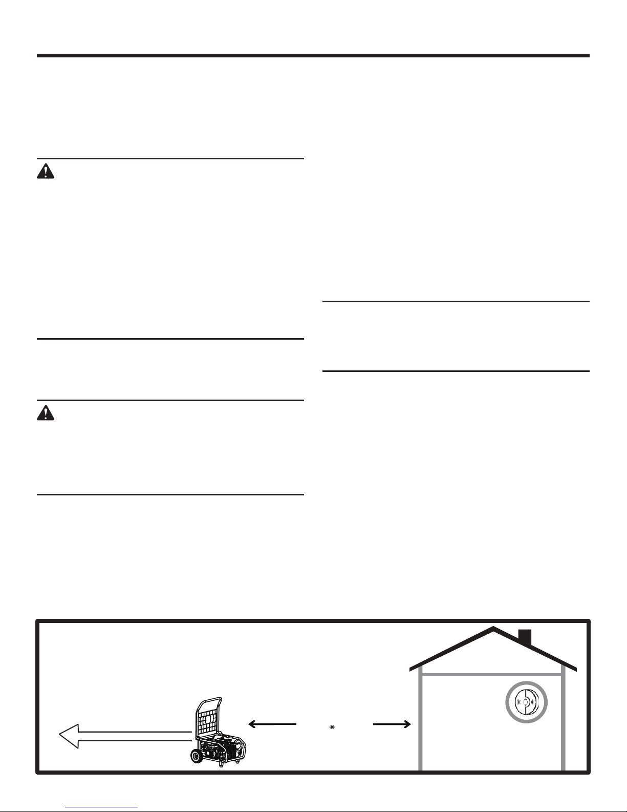
LOCATE AIR COMPRESSOR AT LEAST 20 FT.* AWAY TO REDUCE
THE RISK OF CARBON MONOXIDE GETTING INSIDE THE HOME
* Minimum distance as recommended by U.S. Department of Health and Human
Services Centers for Disease Control and Prevention (www.cdc.gov/co). Your specific
home and/or wind conditions may require additional distance.
Exhaust (CO)
Direct exhaust AWAY
from all windows, doors,
and vents.
KEEP AT LEAST
20 FT. AWAY
Only use OUTSIDE and
FAR AWAY from windows,
doors, and vents.
12 – English
CO Detector
in Living Areas
Page 13
OPERATION
Allow the engine to run for 30 seconds, then move the
choke lever to the RUN position and place the pressure
unloader in the horizontal position.
NOTE: Once the air compressor is started, pressure
inside the air tank will build until the compressor reaches
150 psi. After reaching maximum tank pressure the
engine will idle allowing the pressure inside the air tank to
decrease until it reaches a preset level. When the pressure
falls below the preset level, the engine will accelerate and
provide additional air pressure.
WARNING:
Never exceed the air tool’s pressure rating as
recommended by the manufacturer. When using
this air compressor as an inflation device, always
follow the maximum inflation guidelines stated by
the manufacturer of the item being inflated.
To stop the engine:
Put the on/off switch in the OFF position.
WARNING:
The pump exhaust tube will become hot during
use. Avoid contact with the pump exhaust tube
when stopping the engine.
WARNING:
Always ensure the on/off switch is in the OFF (O)
position and the outlet pressure gauge reads zero
before changing air tools or disconnecting the hose
from the air outlet. Failure to do so could result in
possible serious personal injury.
Turn the fuel valve to the CLOSED position.
NOTICE:
Keep the air compressor on a flat, level surface
during operation. Operation of the unit at an angle
may result in damage to the air compressor and
could void your warranty.
COMPRESSOR TANK AND REMOVABLE TANK
TOGETHER — FOR MAXIMUM TANK CAPACITY
See Figures 16 - 18, pages 25 - 26.
Keep compressor tank and removable tank together for
maximum tank capacity.
Make sure the air compressor is off.
Attach hose(s) to one of the quick-connect couplers
(1/4 in.) on removable tank.
NOTE: If two tools are installed on the removable tank,
they must use the same psi.
Attach a 1/4 in. NPT quick-connect air fitting to accessory
or tool(s) you intend to use.
Insert the other end of the quick-connect air fitting to the
quick coupler on the open end of hose.
Start the air compressor as described in Starting and
Stopping the Air Compressor.
Check that ball valve lever on unregulated air hose is in
the ON position, allowing air flow from compressor tank
to removable tank.
Pull out and rotate pressure regulator knob to desired
line pressure. Turning the knob clockwise increases air
pressure at the outlets; turning counterclockwise reduces
air pressure at the outlets.
Following all safety precautions in this manual and the
manufacturer’s instructions in the air tool manual, you
may now proceed to use your air-powered tool.
USING THE AIR COMPRESSOR
This air compressor can be operated in 3 arrangements for
easy carry and ease of use.
NOTE: Before using the air compressor, always check the
safety valves for proper function as described in Checking
the Safety Valves later in this manual.
CAUTION:
Only use removable tank with air compressor Model
No. GP80150RT to avoid damage to the tool or
risk of personal injury.
WARNING:
The compressor tank will become hot during use.
Failure to avoid contact with the hot surface may
result in serious personal injury.
CAUTION:
Air powered tools may require more air consumption
than this air compressor is capable of providing.
Check the tool manual to avoid damage to the tool
or risk of personal injury.
Control the amount of air flow with the pressure regulator
knob. Turning the knob fully counterclockwise will
completely stop the flow of air.
NOTE: Always use the minimum amount of pressure
necessary for your application. Using a higher pressure
than needed will drain air from the tank more rapidly and
cause the unit to cycle on more frequently.
When finished, always stop the engine and drain the
tanks. Never leave the unit running unattended.
13 – English
Page 14
OPERATION
REMOVABLE TANK ALONE — REGULATED
CARRY TANK FOR SMALL JOBS
See Figures 16 - 17 and 19, pages 25- 26.
The removable tank can be separated from compressor
tank to be carried to remote location for small jobs. One tool
should be used in this instance.
Make sure the air compressor is off.
Rotate pressure regulator knob fully in the counterclock-
wise direction so that the outlet pressure is at zero (0) psi.
Turn ball valve lever on unregulated air hose to OFF posi-
tion.
NOTE: Be sure unregulated air hose is turned off before
connecting or disconnecting from unregulated air intake
coupler.
Disconnect unregulated air hose.
Carefully lift and remove removable tank from compressor
tank and move removable tank to job site.
WARNING:
The compressor tank will become hot during use.
Failure to avoid contact with the hot surface may
result in serious personal injury.
Attach hose to one of the two quick-connect couplers
located on front gauge panel of the removable tank as
previously instructed.
Attach 1/4 in. NPT quick-connect air fitting to accessory
or tool you intend to use.
Insert the other end of the quick-connect air fitting to the
quick-connect coupler on the open end of hose.
Pull out and rotate pressure regulator knob to desired
line pressure. Turning the knob clockwise increases air
pressure at the outlet; turning counterclockwise reduces
air pressure at the outlet.
Following all safety precautions in this manual and the
manufacturer’s instructions in the air tool manual, you
may now proceed to use your air-powered tool.
CAUTION:
Air powered tools may require more air consumption
than this air compressor is capable of providing.
Check the tool manual to avoid damage to the tool
or risk of personal injury.
Control the amount of air flow with the pressure regulator
knob. Turning the knob fully counterclockwise will
completely stop the flow of air.
NOTE: Always use the minimum amount of pressure
necessary for your application. Using a higher pressure
than needed will drain air from the tank more rapidly and
cause the unit to cycle on more frequently.
When finished, always stop the engine and drain the tank.
Never leave the unit running unattended.
COMPRESSOR TANK AND REMOVABLE TANK
SEPARATED AND CONNECTED WITH A HOSE
See Figures 16 - 17 and 20, pages 25 - 26.
The compressor tank and removable tank can be separated
and connected with a hose (up to 50 ft.) for maximum flexibility at job site, remote regulation, to prevent pressure drop
and to keep noise outside.
Make sure the air compressor is off.
Rotate pressure regulator knob fully in the counterclock-
wise direction so that the outlet pressure is at zero (0) psi.
Turn ball valve lever on unregulated air hose to OFF posi-
tion.
NOTE: Be sure unregulated air hose is turned off before
connecting or disconnecting from unregulated air intake
coupler.
Disconnect unregulated air hose.
Carefully lift and remove removable tank from compressor
tank.
Attach unregulated air hose on compressor tank to air
hose (up to 50 ft.).
Attach a 1/4 in. NPT quick-connect air fitting to air hose
and connect to 1/4 in. quick-connect intake coupler on
removable tank.
WARNING:
Only connect unregulated air hose between
compressor tank and unregulated air intake
coupler.
Move removable tank to job area.
Attach hose to one of the two quick-connect couplers
located on front gauge panel of the removable tank as
previously instructed.
NOTE: If two tools are installed on the removable tank,
they must use the same psi.
Attach 1/4 in. NPT quick-connect air fitting to accessory
or tool you intend to use.
Insert the other end of the quick-connect air fitting to the
quick-connect coupler on the open end of hose.
Start the air compressor as described in Starting and
Stopping the Air Compressor.
Turn ball valve lever on unregulated air hose to ON
position, allowing air flow from compressor tank to
removable tank.
Pull out and rotate pressure regulator knob to desired
line pressure. Turning the knob clockwise increases air
pressure at the outlet; turning counterclockwise reduces
air pressure at the outlet.
Following all safety precautions in this manual and the
manufacturer’s instructions in the air tool manual, you
may now proceed to use your air-powered tool.
14 – English
Page 15
OPERATION
CAUTION:
Air powered tools may require more air consumption
than this air compressor is capable of providing.
Check the tool manual to avoid damage to the tool
or risk of personal injury.
Control the amount of air flow with the pressure regula-
tor knob. Turning the knob fully counterclockwise will
completely stop the flow of air.
NOTE: Always use the minimum amount of pressure
necessary for your application. Using a higher pressure
than needed will drain air from the tank more rapidly and
cause the unit to cycle on more frequently.
When finished, always stop the engine and drain the
tanks. Never leave the unit running unattended.
DRAINING THE TANKS
See Figure 21, page 27.
To help prevent tank corrosion and keep moisture out of the
air used, the air tanks of the compressor should be drained
daily.
NOTE: The air compressor has two tanks and two drain
valves. Be sure to perform this operation for each tank.
To drain:
Make sure the air compressor is off.
Pull the ring on the safety valve to release air until tank
pressure gauge reads less than 20 psi.
Release the ring.
Rotate drain valve counterclockwise (ON) to open.
Tilt tank to drain moisture from tank into a suitable
container.
NOTE: Condensate is a polluting material and should be
disposed of in compliance with local regulations.
If drain valve is clogged, release all air pressure, remove
and clean valve, then reinstall.
WARNING:
Stop the air compressor, disconnect the spark
plug wire, and release all air from the tanks before
servicing. Failure to depressurize tanks before
attempting to remove valve can cause serious
personal injury.
Rotate drain valve clockwise (OFF) until tightly closed.
Repeat above procedure for second tank.
WARNING:
RISK OF BURSTING. All compressed air
tanks have a limited lifespan. The lifespan can
be affected by a number of factors, including
operating conditions of the air compressor, proper
maintenance of the tank, and unauthorized repairs
and modifications. Since deterioration of the tank
can occur internally with no outward signs, the
air tank(s) on this compressor MUST be removed
from service by the end of the year shown on the
data label.
Tank life may be extended beyond this date by
having a certified tank inspection performed
before this date, and every 5 years following this
date, for as long as the tank is in use. Use of the
air compressor after this date without passing the
certified inspection increases the risk of an air tank
rupture, which could result in serious personal
injury.
CHECKING THE SAFETY VALVES
See Figure 21, page 27.
DANGER:
Do not attempt to tamper with the safety valves.
Anything loosened from this device could fly up
and hit you. Failure to heed this warning could
result in death or serious personal injury.
Safety valves will automatically release air if the air tank
pressure exceeds the preset maximum. The valves should be
checked before each day of use by pulling the ring by hand.
NOTE: The air compressor has two safety valves. Be sure
to check both.
Start the air compressor and allow the tanks to fill. The
compressor will shut off when the pressure reaches the
preset maximum.
Turn the air compressor off.
Pull the rings on both safety valves to release air for three
to five seconds.
WARNING:
If air leaks after the ring has been released, or if
the valve is stuck and cannot be actuated by the
ring, do not use the air compressor until the safety
valve has been replaced. Use of the air compressor
in this condition could result in serious personal
injury.
15 – English
Page 16

OPERATION
MOVING THE AIR COMPRESSOR
See Figure 22, page 27.
Raise the handle to the up position.
Make sure the air compressor is off.
Close the fuel valve.
With your foot on the rear of the frame, tilt the machine
toward you until it balances on the wheels, then roll the
machine to the desired location.
Allow 30 minutes of “cool down” time before storing the
machine.
CHANGING COUPLERS AND FITTINGS
FROM 1/4 IN. SIZE TO 3/8 IN. SIZE
See Figures 23 - 24, page 27.
This air compressor is equipped with high flow 3/8-in. air line
construction, but features couplings and fittings with 1/4-in.
internal diameter on all the air outlets since this is the most
common fitting size in use.
For optimal performance, you can replace these 1/4-in. couplings with 3/8-in. internal diameter couplings and fittings
(not provided). This will allow you to achieve higher volume
air flow with lower pressure drop.
To replace the fittings:
Turn off the air compressor and release all pressure from
both air tanks.
Using an adjustable wrench, remove the 1/4-in. quick
connect couplers and air reducers.
Apply pipe sealant to new 3/8-in. couplers and then install.
Tighten securely.
Disconnect the unregulated air fitting from the unregulated
air intake coupler.
Remove the 1/4-in. unregulated air intake coupler and air
reducer.
Apply pipe sealant to new 3/8-in. coupler and then install.
Tighten securely.
Remove the 1/4-in. unregulated air fitting and air reducer.
Apply pipe sealant to new 3/8-in. air fitting and then install.
Tighten securely.
Connect the new unregulated air fitting into the new
unregulated air intake coupler.
16 – English
Page 17
MAINTENANCE
Normal maintenance, replacement or repair of emission control devices and systems may be performed by any qualified
repair establishment or individual with original or equivalent
parts. Warranty and recall repairs must be performed by an
authorized service center; please contact customer service
for assistance.
WARNING:
When servicing use only recommended or
equivalent replacement parts. Use of any other
parts may create a hazard or cause product
damage.
WARNING:
Always wear eye protection with side shields
marked to comply with ANSI Z87.1. Failure to do
so could result in objects being thrown into your
eyes resulting in possible serious injury.
WARNING:
Before inspecting, cleaning or servicing the
machine, shut off engine, wait for all moving parts
to stop, and disconnect spark plug wire and move
it away from spark plug. Failure to follow these
instructions can result in serious personal injury
or property damage.
NOTICE:
Before each use, inspect the entire product for
damaged, missing, or loose parts such as screws,
nuts, bolts, caps, etc. Tighten securely all fasteners
and caps and do not operate this product until all
missing or damaged parts are replaced. Please
contact customer service or a qualified service
center for assistance.
GENERAL MAINTENANCE
Avoid using solvents when cleaning plastic parts. Most
plastics are susceptible to damage from various types of
commercial solvents and may be damaged by their use. Use
clean cloths to remove dirt, dust, oil, grease, etc.
As a routine part of air compressor maintenance, it is also
advised that the oil is routinely checked for proper levels.
WARNING:
Do not at any time let brake fluids, gasoline,
petroleum-based products, penetrating oils, etc.,
come in contact with plastic parts. Chemicals can
damage, weaken or destroy plastIc which may
result in serious personal injury.
CLEANING EXHAUST PORT AND MUFFLER
NOTICE:
This product is not equipped with a spark arrestor
and cannot be used on U.S. forest lands; in
addition, product users must comply with Federal,
State, and local fire prevention regulations.
Check with appropriate authorities. Refer to
accompanying engine manual for maintenance
and replacement parts.
Depending on the type of fuel used, the type and amount of
oil used, and/or your operating conditions, the exhaust port
and/or muffler may become blocked with carbon deposits.
If you notice a power loss with your gas powered tool, you
may need to remove these deposits to restore performance.
We highly recommend that only qualified service technicians
perform this service.
CLEANING THE AIR FILTERS
See Figure 25 - 26, page 27.
The air compressor has air filters to protect both its engine
and pump. Dirty air filters will cause starting difficulty, loss
of performance, and shorten the life span of the compressor.
Check the air filters monthly. For best performance, replace
both air filters at least once a year.
Cleaning the engine air filter:
Turn off the air compressor.
Lift the latch on the air filter cover to open, then remove
the air filter cover.
Lift the edge of the air filter carefully and pull it out.
Wash the air filter with warm, soapy water.
Rinse and squeeze to dry.
Put small amount of motor oil (SAE 30, or SAE 10W30) on
the filter sponge. Squeeze out the excess oil then reinstall
the air filter.
NOTE: Make sure the filter is seated properly inside the
housing. Installing the filter incorrectly will allow dirt to
enter the engine, causing rapid engine wear.
Reinstall the air filter cover.
Cleaning the pump air filter:
Turn off the air compressor.
With one hand, secure the pump air filter cover. With the
other hand, remove the 6 mm soc. hex hd. bolts securing
the cover.
Remove the cover.
Remove the air filter from the housing.
Wash the air filter with warm, soapy water.
Rinse and squeeze to dry.
Reinstall the air filter.
Place the air filter cover back on the unit. Reinstall hex
bolts and tighten to secure.
17 – English
Page 18

MAINTENANCE
CHANGING THE ENGINE OIL
See Figure 27, page 27.
Replace the engine oil after the first 100 hours of operation
and every 100 hours following the first oil change.
Turn off the air compressor.
Place a suitable container underneath the drain hole to
collect used oil.
Remove the drain line cap with an adjustable wrench.
Allow lubricant to drain completely.
NOTE: Drain the lubricant while the engine is still warm
but not hot. Warm lubricant will drain quickly and more
completely.
WARNING:
Do not change engine lubricant while it is hot.
Accidental contact with hot engine lubricant could
result in serious burns.
Reinstall the cap and tighten with the wrench.
Remove the engine oil cap/dipstick.
Refill with lubricant following the instructions in the
Adding/Checking Engine Oil section. For amount of oil
needed to refill, see Product Specifications earlier in this
manual or the accompanying engine manual, if applicable.
Reinsert the oil cap/dipstick securely into the oil fill hole.
NOTE: Consult hazardous waste management guidelines in
your area for the proper way to dispose of used oil.
CHANGING THE PUMP OIL
See Figure 28, page 28.
Turn off the air compressor.
Place a suitable container underneath the drain plug to
collect used pump oil.
Loosen the pump oil cap/dipstick. Remove the drain plug
and washer and drain the old pump oil.
NOTE: Drain the oil while the pump is still warm but not
hot. Warm oil will drain quickly and more completely.
Replace the drain plug and washer. Tighten securely.
Refill with pump oil following the instructions in the
Adding/Checking Pump Oil section.
Replace pump oil cap/dipstick and tighten securely.
NOTE: Consult hazardous waste management guidelines in
your area for the proper way to dispose of used oil.
SPARK PLUG MAINTENANCE
See Figures 29 - 30, page 28.
The spark plug must be properly gapped and free of deposits
to ensure proper engine operation. To check:
Turn off the air compressor.
Remove the spark plug cap.
Clean any dirt from around base of spark plug.
Remove spark plug using the spark plug wrench provided.
Inspect spark plug for damage, and clean with a wire
brush before reinstalling. If insulator is cracked or chipped,
spark plug should be replaced. For replacement spark
plug, see Product Specifications earlier in this manual
or the accompanying engine manual, if applicable.
Measure plug gap. The correct gap is 0.023−0.027 in.
(0.6 mm - 0.7 mm). To widen gap, if necessary, carefully
bend the ground (top) electrode. To lessen gap, gently
tap ground electrode on a hard surface.
Seat spark plug in position; thread in by hand to prevent
cross-threading.
Tighten with an adjustable wrench to compress washer.
If spark plug is new, use 1/2 turn to compress washer
appropriate amount. If reusing old spark plug, use 1/8 to
1/4 turn for proper washer compression.
NOTE: An improperly tightened spark plug will become
very hot and could damage the engine.
BELT REPLACEMENT
See Figures 31 - 35, pages 28 - 29.
The air compressor is powered by a belt-driven motor.
Periodically check the belt for wear and replace it when
necessary. Proceed as follows when replacement is required:
Turn off the air compressor and disconnect the spark plug
wire. Allow the engine to cool.
Remove the removable tank following instructions in
Removable Tank Alone — Regulated Carry Tank For
Small Jobs and set aside.
Using an adjustable wrench, remove the following bolts,
washers, nuts, and spacer securing the belt guard:
• one M10 flange hex hd. bolt, lock washer, flat washer,
and spacer from the top of pump
• two M6 soc. hex hd. bolts, lock washers, and square
washers from the ends of the belt guard
• four M6 flange hex hd. bolts, lock washers, flat
washers, and nuts on the sides of the belt guard
Carefully lift the belt guard off the air compressor and set
aside.
Loosen the four engine bolts and nuts securing the engine
in place.
Turn the belt tensioner bolt counterclockwise to move
the engine toward the pump until there is enough slack
in the belt for it to be removed from around the pulleys.
Place the new belt around the small pulley (narrow side
down), then install the belt over the large pulley.
Turn the belt by hand until you are certain it is properly
aligned on the grooves of the pulleys.
Turn the belt tensioner bolt clockwise to move the engine
away from the pump until there is tension in the belt.
18 – English
Page 19

MAINTENANCE
Check belt alignment by placing a straight edge across
the front of the large and small pulley as shown in figures
32 and 33. The straight edge should touch the rim of the
large pulley at two places. When viewed from above, the
belt should be parallel with the straight edge.
NOTE: If the belt is misaligned, move the engine toward
or away from the air tanks.
Check belt tension by squeezing the belt. Using light
pressure, the belt should deflect approximately 1/2 in.
NOTE: If belt tension is not correct, move the engine
toward or away from the pump.
Once belt tension and belt alignment are correct, retighten
engine bolts and nuts.
Reinstall the belt guard and secure with nuts, washers
and bolts.
Replace the removable tank.
STORING THE AIR COMPRESSOR
Store the air compressor with the gas tank empty by running
the air compressor until the gas runs out. Allow 30 minutes
of “cool down” time before storing the machine. Store in a
dry, covered area where the weather can’t damage it.
Air Compressor Tanks:
Release all air from the air tanks.
Drain all moisture from the air tanks, then close drain
valves.
Discharge Fuel:
Drain the fuel tank completely by running the air compressor
until the gas runs out. Stored gas can go stale in 30 days.
Engine Oil:
Drain the oil and replace with fresh, clean oil.
Spark Plug:
Disconnect spark plug wire and remove the spark plug.
Pour about a teaspoon of clean, air-cooled, four-cycle oil
through the spark plug hole into the combustion chamber.
Leaving the spark plug out, pull the starter cord two or
three times to coat the inside of the cylinder wall.
Inspect the spark plug and clean or replace, as necessary.
Reinstall the spark plug, but leave the spark plug wire
disconnected.
Air Filter:
Clean the air filter.
PREPARING FOR USE AFTER STORAGE
Pull the recoil starter three or four times to clean oil from
the combustion chamber.
Remove spark plug from the cylinder. Wipe oil from the
spark plug and return it to the cylinder.
Reconnect the spark plug wire.
Refuel the machine as described earlier in the operator’s
manual.
PERIODIC MAINTENANCE SCHEDULE TABLE
NOTE: If a separate engine manual is provided for this air compressor, please follow the maintenance schedule provided
in the engine manual instead of the maintenance information listed below.
Maintenance Items Each use 100 hours
Check pump oil level X
Check engine oil level X
Check for oil leaks - inspect oil seals, drain plug, oil plug,
sight glass
Change pump oil X
Change engine oil X
Check/clean engine and pump air filters X
X
19 – English
Page 20

TROUBLESHOOTING
PROBLEM POSSIBLE CAUSE SOLUTION
Engine will not start. On/stop switch is in off position.
No fuel.
Fuel valve is closed.
Spark plug faulty, fouled, or
improperly gapped.
Choke lever is in RUN position.
Turn the on/stop switch to ON.
Fill fuel tank.
Open fuel valve.
Replace spark plug.
Move choke lever to START position.
Engine lacks power. Fuel element clogged.
Defective pressure unloader.
Air tank pressure drops when compressor shuts off.
Excessive moisture in discharge air. Excessive water in air tanks.
Compressor runs continuously. Defective pressure unloader.
Air output lower than normal. Broken inlet valves.
Compressor cycles on and off
continuously.
Loose connections (fittings, tubing, etc.).
Loose drain valve.
Pressure unloader leaking.
High humidity.
Excessive air usage.
Piston rings are worn.
Connections leaking.
Pressure unloader clogged. Take compressor to a qualified service
Check air filter element. Clean or replace
as needed.
Take compressor to a qualified service
center.
Check all connections with soap and
water solution and tighten.
Tighten drain valve.
Take compressor to a qualified service
center.
DANGER:
Do not disassemble pressure
unloader, tank drain valves or safety
relief valve with air in tank — bleed
tanks.
Drain tanks.
Move to area of less humidity; use air
line filter.
Take compressor to a qualified service
center.
Decrease air usage; compressor not
large enough for tool’s requirement.
Replace piston rings; Call customer
service for assistance.
Take compressor to a qualified service
center.
Tighten connections.
center.
20 – English
Page 21

TROUBLESHOOTING
PROBLEM POSSIBLE CAUSE SOLUTION
Excessive pump oil use. Pump oil cap vent clogged.
Incorrect pump oil.
Pump air filter clogged/dirty.
Too much pump oil in crankcase.
Piston rings worn.
Cylinder scored.
If problem persists after trying the above solutions, contact customer service or a qualified service center for assistance.
NOTICE:
As the equipment owner, you are responsible for the performance of the required maintenance listed in the Maintenance
section. It is recommended that you retain all receipts covering maintenance on your equipment. Neglecting or failing
to perform the required maintenance may increase emissions, decrease fuel efficiency, degrade performance, cause
irreversible engine damage, and/or void your warranty.
NOTE: ILLUSTRATIONS START ON PAGE 23 AFTER
Remove clog from pump oil cap or
replace cap, if necessary.
Use only SAE 5W40 synthetic pump oil.
Clean/replace pump air filter.
Drain pump oil to the proper level.
Take compressor to a qualified service
center.
Take compressor to a qualified service
center.
FRENCH AND SPANISH LANGUAGE SECTIONS.
This product has a 90-Day Satisfaction Guarantee Policy, as well
as a Three-year Limited Warranty. For Warranty and Policy details,
please go to www.RIDGID.com or call (toll free) 1-866-539-1710.
21 – English
Page 22

WARRANTY
LIMITED 3 YEAR ENGINE WARRANTY
Limited Manufacturer’s Warranty from Subaru Robin
(Effective with engines purchased from Robin America, Wood Dale, IL, after April 1, 2008)
Robin America, Inc., a division of Fuji Heavy Industries, Ltd. (herein “Subaru Robin”), warrants that each new engine sold by it
will be free, under normal use and service, from defects in material and workmanship for a period listed below from the date
of sale to the original retail purchaser. Subaru Robin’s obligation under this Limited Warranty shall be limited to the repair and
replacement, at Subaru Robin’s option, of any part or parts which upon examination is/are found, in Subaru Robin’s judgment,
to have been defective in material or workmanship. It shall be a condition of Subaru Robin’s obligation under this Limited
Warranty that Subaru Robin, directly or through one of its Distributors or Service Centers authorized to service the particular
engine involved, receive prompt notice of any warranty claim and that the engine or the part or parts claimed to be defective
be promptly delivered, transportation prepaid, to such Distributor or Service Center for inspection and repair. All repairs qualifying under this Limited Warranty must be performed by Subaru Robin or one of its authorized Distributors or Service Centers.
WARRANTY PERIODS:
Subaru Robin Four-Cycle, Air-cooled, Gasoline Engines - Limited 3 YEAR Warranty (EX / EH and SP Series 4.3hp or
greater)
The repair or replacement of any part or parts under this Limited Warranty shall not extend the term of the engine warranty
beyond the original term as set forth above.
LIMITATIONS AND EXCLUSIONS: This Limited Warranty shall not apply to:
Bent or broken crankshaft or resultant damage caused by vibration related to a bent or broken crankshaft. Also, damage
caused by loose engine mounting bolts or improper or imbalanced accessories or blades mounted to the crankshaft.
Repairs required because of prolonged storage including damage caused by old or contaminated fuel in the fuel tank, fuel
lines or carburetor, sticky valves or corrosion and rust of engine parts.
Repair required due to overheating. (Most often caused by overloaded or clogged or damaged or missing flywheel, fan,
inlet air passages, cooling fins or air shrouds).
Dirt or grit related wear caused by improper air cleaner maintenance (most often resulting in worn piston, piston rings,
cylinders, valves, valve guides, carburetor or other internal components).
Broken or scored parts caused by low lubricant level, dirty or improper grade of lubricant.
Engine tune-ups and normal maintenance service including, but not limited to, valve adjustment, normal replacement of
service items, fuel and lubricant, etc.
Any engine which has been subject to negligence, misuse, accident, mis-application or over-speeding.
Any engine that has been installed, repaired, or altered by anyone in a manner which in Subaru Robin’s sole judgment
adversely affects its performance or reliability.
Any engine which has been fitted with or repaired with parts or components not manufactured or approved by Subaru
Robin which in Subaru Robin’s sole judgment adversely affects its performance or reliability.
Instances when normal use has exhausted the life of a component or an engine.
The customer is responsible for all transportation charges in connection with any warranty work.
Subaru Robin reserves the right to modify, alter or improve any engines or parts without incurring any obligation to modify or
replace, any engine or parts previously sold without such modification, alternation or improvement.
No person is authorized to give any other warranty or to assume any additional obligation on Subaru Robin’s behalf unless
made in writing and signed by an officer of Subaru Robin.
Some states do not allow limitations on how long an implied warranty lasts or the exclusion or limitation of incidental or con-
sequential damages, so the above limitation(s) or exclusion(s) may not apply to you. This warranty gives you specific legal
rights and you may also have other legal rights which vary from state to state.
THIS WARRANTY, AND SUBARU ROBIN’S OBLIGATION HERE UNDER, ARE IN LIEU OF ANY OTHER WARRANTIES OR
OBLIGATIONS OF ANY KIND, EXPRESSED OR IMPLIED, INCLUDING ANY WARRANTIES OF MERCHANTABILITY OR FITNESS FOR A PARTICULAR PURPOSE. THERE ARE NO WARRANTIES WHICH EXTEND BEYOND THE DESCRIPTION ON THE
FACE HERE-OF. SUBARU ROBIN SHALL IN NO EVENT BE LIABLE FOR ANY CONSEQUENTIAL OR INCIDENTAL DAMAGES.
22 – English
Page 23

RÈGLES DE SÉCURITÉ GÉNÉRALES
l’utilisation d’un compresseur peut entraîner des
AVERTISSEMENT :
Lire et veiller à bien comprendre toutes les
instructions. Le non-respect de toutes les
instructions ci-dessous peut entraîner un choc
électrique, un incendie et/ou des blessures graves.
CONSERVER CES INSTRUCTIONS
LIEU DE TRAVAIL
Garder le lieu de travail propre et bien éclairé. Les
établis encombrés et les endroits sombres sont propices
aux accidents. Le sol ne doit pas être rendu glissant par
de la cire ou de la sciure.
Ne pas utiliser le compresseur dans des atmosphères
explosives, par exemple en présence de liquides,
gaz ou poussières inflammables. Les compresseurs
produisent des étincelles risquant d’enflammer les
poussières ou vapeurs.
Garder les badauds, enfants et visiteurs à l’écart
pendant l’utilisation d’outils. Les distractions peuvent
causer une perte de contrôle.
Utiliser le compresseur d’air dans un endroit dégagé,
à au moins 460 mm (18 po) de toute paroi ou objet
risquant de gêner l’entrée de l’air dans les ouvertures
de ventilation.
SÉCURITÉ PERSONNELLE
Toujours porter une protection oculaire munie d’écrans
latéraux certifiée conforme à la norme ANSI Z87.1,
ainsi qu’une protection auditive lors de l’utilisation de
cet outil.
Il incombe à l’employeur et/ou l’utilisateur de veiller à
ce qu’une protection oculaire adéquate soit utilisée.
Nous recommandons d’utiliser un masque facial à champ
de vision se portant par-dessus des lunettes de vue ou de
sécurité et potégeant des débris projetés sur le devant et
les côtés. Toujours porter une protection oculaire certifiée
conforme à la norme ANSI Z87.1.
Des équipements de protection supplémentaires sont
requis dans certains environnements. Par exemple,
le lieu de travail peut présenter un niveau de bruit
susceptible d’entraîner des lésions auditives. Il incombe à
l’opérateur et à l’utilisateur qu’une protection audidive soit
fournie et utilisée par l’opérateur et les autres personnes
se trouvant sur le lieu de travail. Certains environnements
requièrent le port d’un casque. Il incombe à l’employeur
et/ou l’utilisateur de veiller à ce qu’un casque conforme
à la norme ANSI Z89.1 soit utilisé.
Rester attentif, prêter attention au travail et faire
preuve de bon sens lors de l’utilisation de tout
compresseur. Ne pas utiliser cet outil en état de
fatigue ou sous l’influence d’alcool, de drogues ou
de médicaments. Un moment d’inattention pendant
blessures graves.
Porter une tenue appropriée. Ne porter ni vêtements
amples, ni bijoux. Attacher ou couvrir les cheveux
longs. Garder les cheveux, les vêtements et les gants
à l’écart des pièces en mouvement. Les vêtements
amples, bijoux et cheveux longs peuvent se prendre dans
les pièces en mouvement.
Ne pas travailler hors de portée. Toujours se
tenir bien campé et en équilibre. Une bonne
tenue et un bon équilibre permettent de mieux
contrôler l’outil en cas de situation imprévue.
Utiliser l’équipement de sécurité. Toujours porter une
protection oculaire. Suivant les conditions, le port d’un
masque antipoussière, de chaussures de sécurité, d’un
casque ou d’une protection auditive est recommandé.
Ne pas utiliser l’outil sur une échelle ou un support
instable. Une bonne tenue et un bon équilibre permettent
de mieux contrôler l’outil en cas de situation imprévue.
UTILISATION ET ENTRETIEN DE L’OUTIL
Pour l’utilisation à l’extérieur seulement.
Ne pas dépasser les pressions nominales des
composants du système.
Protéger les flexibles d’alimentation et d’outil contre
les dommages et risques de perforation. Garder le
flexible et le cordon d’alimentation électrique à l’écart de la
chaleur, de l’huile, des solvants et sols humides ou mouillés.
Avant chaque utilisation, s’assurer que les fexibles
ne sont pas affaiblis ou endommagés et vérifier tous
les branchements. Ne pas utiliser le compresseur si les
flexibles ne sont pas en bon état. Acheter de nouveaux
flexibles ou contacter un centre de réparations qualifié,
pour les faire inspecter ou réparer.
Relâcher toutes les pressions du système lentement.
La projection de poussières et de débris peut être
dangereuse.
Ranger les outils non utilisés hors de portée des
enfants et des personnes n’ayant pas reçu des
instructions adéquates. Dans les mains de personnes
n’ayant pas reçu des instructions adéquates, les outils
sont dangereux.
Entretenir soigneusement les outils. Respecter toutes
les instructions d’entretien. Les outils correctement
entretenus sont plus faciles à contrôler.
Vérifier qu’aucune pièce mobile n’est mal alignée,
grippée ou brisée et s’assurer qu’aucun autre
problème risque d’affecter le bon fonctionnement de
l’outil. En cas de dommages, faire réparer l’outil avant de
l’utiliser de nouveau. Beaucoup d’accidents sont causés
par des outils mal entretenus.
Garder l’extérieur du compresseur sec, propre et
exempt d’huile ou de graisse. Toujours utiliser un chiffon
propre pour le nettoyage. Ne jamais utiliser de liquide de
3 – Français
Page 24

RÈGLES DE SÉCURITÉ GÉNÉRALES
freins, d’essence, de produits à base de pétrole ou de
solvants puissants pour nettoyer l’outil. Le respect de
cette règle réduira les risques de perte du contrôle et
d’endommagement du boîtier en plastique.
Garder le moteur dépourvu d’herbe, feuilles ou graisse
pour réduire le risque d’incendie.
Maintenir tous les dispositifs de protection en place
et en bon état de fonctionnement. Ne jamais utiliser
l’outil avec des couvercles ou dispositifs de protection
retirés. S’assurer que tous les dispositifs de protection
fonctionnent correctement avant chaque utilisation.
Ne pas faire tourner le moteur dans un espace confiné
où des vapeurs toxiques de monoxyde de carbone
peuvent s’accumuler. Le monoxyde de carbone, un gaz
incolore, inodore et extrêmement toxique peut causer
une perte de conscience et être mortel.
Garder le tuyau d’échappement exempt de débris.
Ne pas utiliser à proximité de buissons secs, brindilles,
chiffons ou autres matériaux inflammables.
Ne jamais ramasser ni porter la machine lorsque le
moteur tourne.
Ne jamais mettre la machine en marche si de la glace
s’est formée sur quelque partie que ce soit.
Toujours utiliser la machine sur une surface plane.
Si le moteur est incliné, il peut se gripper à cause d’un
graissage insuffisant (même au niveau maximum d’huile).
Ne jamais essayer de faire des réglages pendant que
le moteur tourne (sauf en cas de recommandations
spécifiques du fabricant).
Les dispositifs de protection doivent toujours couvrir
des pièces en rotation quand le moteur tourne.
Garder l’entrée d’air (poignée du lanceur et corde) et le
côté échappement du moteur au à au moins 3 pi (914 mm)
des structures, obstacles et autres objets combustibles.
Garder le moteur à l’écart des articles inflammables
et autres matières dangereuses.
Rester à l’écart des pièces brûlantes. L’échappement
et d’autres pièces de moteur deviennent brûlantes, se
montrer prudent.
Ne toucher ni la bougie, ni le câble d’allumage lors du
démarrage et du fonctionnement du moteur.
Vérifier le serrage des flexibles et raccords de
carburant et s’assurer de l’absence de fuites avant
chaque utilisation.
Vérifier le serrage de la boulonnerie avant chaque
utilisation. Un boulon ou écrou desserré peut causer de
sérieux problèmes de moteur.
Toujours effectuer l’approvisionnement en carburant à
l’extérieur. Ne jamais refaire le plein en intérieur ou dans
un endroit insuffisamment ventilé.
Ne jamais remiser la machine avec du carburant dans
le réservoir de carburant dans un local où des sources
d’allumage, telles que radiateurs à gaz et à eau chaude,
les séchoirs à vêtements, etc., sont présentes.
Si le réservoir d’essence doit être vidangé, faire la
vidange à l’extérieur et dans un contenant d’essence
approuvé et loin des sources d’allumage.
Manipuler le carburant avec précaution pour éviter les
risques d’incendies et de brûlures. Le carburant est
extrêmement inflammable.
Ne pas fumer pendant la manipulation du carburant.
Faire l’appoint de carburant avant de lancer le moteur.
Ne jamais retirer le couvercle du réservoir de carburant
ni ajouter du carburant pendant que le moteur tourne ou
quand le moteur est chaud.
Desserrer le bouchon du réservoir lentement pour
relâcher la pression et éviter que le carburant s’échappe.
Remettre en place tous les bouchons de conteneur
et de réservoir de carburant et les serrer fermement.
Essuyer tout le carburant éventuellement répandu.
S’éloigner de 9 m (30 pi) du point d’approvisionnement
avant de lancer le moteur.
Si du carburant est renversé, ne pas essayer de
démarrer le moteur mais éloigner la machine de l’endroit
et éviter de créer une source d’inflammation jusqu’à ce
que les vapeurs de carburant se soient dissipées.
N’essayer en aucun cas de brûler le carburant répandu.
Laisser le moteur refroidir avant de remiser l’outil.
Remiser le carburant dans un endroit frais, bien aéré,
à l’écart d’étincelle et/ou d’appareils produisant des
flammes.
Conserver le carburant dans des jerrycans spécialement
conçus à cet effet.
Pour le transport sur ou dans un véhicule, le réservoir
doit être vide et la machine bien arrimée.
Veiller à garder une distance d’au moins 3 pi (914 mm)
des matériaux combustibles.
SERVICE
Utiliser exclusivement des pièces recommandées ou
équivalentes pour les réparations. Se conformer aux
instructions de la section Entretien de ce manuel.
L’usage de pièces non autorisées ou le non respect des
instructions d’entretien peut présenter des risques de
blessures.
Le dépannage des outils doit être confié exclusivement
à un personnel qualifié. Les réparations ou entretiens
effectués par des personnes non qualifiées présentent
des risques de blessures.
Débrancher le fil de la bougie, ouvrir le robinet de
purge pour relâcher la pression, laisser l’eau s’écouler
et laisser la machine refroidir avant de procéder à tout
entretien. Après avoir arrêté le compresseur, tourner le
bouton du détendeur à fond vers la gauche.
4 – Français
Page 25

RÈGLES DE SÉCURITÉ PARTICULIÈRES
Apprendre à connaître compresseur d’aire. Lire
attentivement le manuel d’utilisation. Apprendre les
applications et les limites de l’outil, ainsi que les risques
spécifiques relatifs à son utilisation. Le respect de cette
règle réduira les risques d’incendie, de choc électrique
et de blessures.
Purger le réservoir après chaque journée de travail.
Si le compresseur ne doit pas être utilisé pendant un
certain temps, il est préférable de laisser le robinet de
purge ouvert. Cela permettra d’évacuer complètement
l’humidité et aidera à empêcher la corrosion de l’intérieur
du réservoir.
Risque d’incendie ou d’explosion. Ne pas vaporiser de
liquides inflammables dans un endroit confiné. La zone
de pulvérisation doit être bien ventilée. Ne pas fumer
pendant la pulvérisation ou pulvériser en présence de
flammes. Garder les compresseurs le plus loin possible
des zones de pulvérisation, au moins à 4,6 m (15 pi) de
la zone de pulvérisation et de toutes vapeurs explosives.
Risque d’éclatement. Ne pas ajuster le régulateur pour
une pression de sortie supérieure à la pression maximale
indiquée sur l’accessoire utilisé ou sur l’article gonflé. La
pression ne doit jamais dépasser
Une fois l’an, s’assurer que le réservoir n’est pas
rouillé ou piqué et ne présente aucun défaut risquant
de le rendre dangereux. Ne jamais percer ou souder le
réservoir.
S’assurer que le flexible n’est ni bloqué, ni accroché.
Un flexible emmêlé ou entortillé peut causer une perte
d’équilibre et être endommagé.
Le compresseur ne doit être utilisé que pour les
applications pour lesquelles il est conçu. Ne pas
altérer ou modifier le compresseur ou l’utiliser pour
des applications pour lesquelles il n’est pas conçu.
Ne pas s’asseoir ou se tenir debout sur le cadre du
compresseur d’air ou tenter d’utiliser le cadre comme
surface de travail.
Ne jamais oublier qu’un usage incorrect ou abusif
de cet outil peut mettre l’opérateur et les autres
personnes présentes en danger.
Ne jamais laisser l’outil sans surveillance avec le
flexible d’air branché.
Ne pas pointer un outil quel qu’il soit vers soi ou
d’autres personnes.
Ne pas utiliser cet outil s’il ne comporte pas
d’autocollant d’avertissement.
Ne pas utiliser un outil qui présente des fuites d’air
ou ne fonctionne pas correctement.
Toujours débrancher l’outil des alimentations
pneumatique et le fil de la bougie avant d’effectuer des
réglages ou entretiens et lorsque l’outil n’est pas utilisé
1 034 kPa (150 psi).
Ne pas essayer de tirer ou de transporter le
compresseur par son flexible.
La consommation d’air de l’outil peut être supérieure
à la capacité de ce compresseur.
Toujours respecter les consignes de sécurité du
fabricant de l’outil pneumatique, ainsi que toutes les
règles de sécurité d’utilisation du compresseur. Le
respect de cette consigne réduira les risques de blessures
graves.
Ne jamais diriger le jet d’air comprimé vers des
personnes ou animaux. Veiller à ne pas projeter de la
poussière ou de la saleté vers soi-même ou d’autres
personnes. Le respect de cette règle réduira les risques
de blessures graves.
Ne pas utiliser ce compresseur pour la pulvérisation
de produits chimiques. L’inhalation de vapeurs toxiques
peut causer des lésions pulmonaires. Le port d’un
respirateur peut être nécessaire dans les environnements
poussiéreux ou lors de la pulvérisation de peinture. Ne
pas porter lorsque vous êtes en train de peindre.
Inspecter régulièrement les flexibles et , s’ils sont
endommagés, les confier au centre de réparations
qualifié.
Vérifier l’état des pièces. Avant d’utiliser le
compresseur de nouveau, examiner soigneusement
les pièces et dispositifs de protection qui semblent
endommagés afin de déterminer s’ils fonctionnent
correctement et remplissent les fonctions prévues.
Vérifier l’alignement des pièces mobiles, s’assurer
qu’aucune pièce n’est bloquée ou cassée, vérifier la
fixation de chaque pièce et s’assurer qu’aucun autre
problème ne risque d’affecter le bon fonctionnement
de l’outil. Toute protection ou pièce endommagée
doit être correctement réparée ou remplacée dans
un centre de réparations qualifié. Le respect de
cette consigne réduira les risques de choc électrique,
d’incendie et de blessures graves.
Ne jamais emmagasiner l’outil avec l’air connecté.
Emmagasiner l’outil avec l’air connecté peut avoir pour
résultat vider imprévu et la blessure personnelle, sérieuse
et possible.
Protection respiratoire. Porter un masque facial ou
respiratoire si le travail produit de la poussière. Le respect
de cette règle réduira les risques de blessures graves.
Conserver ces instructions. Les consulter fréquemment
et les utiliser pour instruire les autres utilisateurs éventuels.
Si cet outil est prêté, il doit être accompagné de ces
instructions.
5 – Français
Page 26

SYMBOLES
Les termes de mise en garde suivants et leur signification ont pour but d’expliquer le degré de risques associé
à l’utilisation de ce produit.
SYMBOLE SIGNAL SIGNIFICATION
Indique une situation extrêmement dangereuse qui, si elle n’est pas évitée,
DANGER :
aura pour conséquences des blessures graves ou mortelles.
AVERTISSEMENT :
ATTENTION :
AVIS :
Certains des symboles ci-dessous peuvent être utilisés sur l’produit. Veiller à les étudier et à apprendre leur signification.
Une interprétation correcte de ces symboles permettra d’utiliser l’produit plus efficacement et de réduire les risques.
SYMBOLE NOM
(Sans symbole d’alerte de sécurité) Indique une information importante
Symbole d’alerte de sécurité Indique un risque de blessure potentiel.
Lire le manuel d’utilisation
Protection oculaire
Indique une situation potentiellement dangereuse qui, si elle n’est pas évitée,
Indique une situation potentiellement dangereuse qui, si elle n’est pas évitée,
pourrait entraîner des blessures graves ou mortelles.
pourraît entraîner des blessures légères ou de gravité modérée.
ne concernant pas un risque de blessure comme une situation pouvant
occasionner des dommages matériels.
DÉSIGNATION / EXPLICATION
Pour réduire les risques de blessures, l’utilisateur doit lire et
veiller à bien comprendre le manuel d’utilisation avant d’utiliser
ce produit.
Toujours porter une protection oculaire avec écrans latéraux
certifiée conforme à la norme ANSI Z87.1.
Avertissement concernant
l’humidité
Risque d’éclatement
Risque d’incendie ou
d’explosion
Risque de choc électrique
Surface brûlante
Risques d’inhalation
Ne pas exposer à la pluie ou l’humidité.
Ne pas ajuster le régulateur pour une pression de sortie supérieure
à la pression maximale indiquée sur l’accessoire utilisé ou sur
l’article gonflé. La pression ne doit jamais dépasser 1 034 kPa
(150 psi).
Ne pas vaporiser de liquides inflammables dans un endroit confiné.
La zone de pulvérisation doit être bien ventilée. Ne pas fumer
pendant la pulvérisation ou pulvériser en présence de flammes.
Garder les compresseurs le plus loin possible des zones de
pulvérisation, au moins à 4,6 m (15 pi) de la zone de pulvérisation
et de toutes vapeurs explosives.
Tension dangereuse : Débrancher de la prise secteur avant de faire
des réparations. Le compresseur doit être mis à la terre.
Pour éviter les risques de blessures ou de dommages, éviter tout
contact avec les surfaces brûlantes.
L’air sortant directement du compresseur ne doit jamais être utilisé
pour la respiration.
6 – Français
Page 27

GLOSSAIRE
Filtre à air
Élément poreux contenu dans un boîtier en métal ou
plastique, monté sur la culasse du compresseur pour
débarasser l’air d’alimentation de toutes ses impuretés.
Réservoir d’air
Cylindrical component which contains the compressed air.
Carter de courroie
Protège l’opérateur contre le contact avec la courroie et les
rotations de courroies.
Pression de déclenchement
La basse pression à laquelle le moteur passe automatiquement
à la pleine vitesse.
Pression d’arrêt
La haute pression à laquelle le moteur passe automatiquement
à la marche au ralenti.
NPT (National Pipe Thread)
Un ruban d’étanchéité de filetage doit être utilisé sur tous
les raccords filetés, pour empêcher les fuites.
Commutateur marche / arrêt
Commande permettant de mettre le compresseur en marche
et de l’arrêter. Le manostat ne peut commander la mise en
marche du moteur que si le commutateur est en position
de MARCHE (l).
Bouton de régulation de pression
Permet de contrôler la pression d’alimentation de l’outil. La
rotation du bouton dans un sens ou dans l’autre augmente
ou réduit la pression d’air.
Dispositif de délestage
Contrôle la vitesse du moteur du compresseur. Le moteur
marche au ralenti lorsque la pression de déclenchement
du réservoir est atteinte et commande la pleine vitesse du
moteur dès que la pression est inférieure à la pression de
déclenchement.
Livres par pouce carré (PSI)
Mesure de la pression exercée par la force de l’air. La
pression est indiquée par un manomètre monté sur le
compresseur.
Pompe
Produit l’air comprimé au moyen d’un piston alternatif à
l’intérieur du cylindre.
Coupleur à ressort
Les coupleurs à raccord rapide de 6,35 mm (1/4 po) facilitent
la fixation des tuyaux flexibles à air au compresseur pour
l’opérateur.
Manomètre de détendeur
Indique la pression de ligne. La pression de ligne se règle au
moyen du bouton de commande du détendeur.
Valve de sécurité
Empêche la pression d’air du réservoir de dépasser une
limite prédéterminée.
PCSM (Pieds cubes standard minute) ou PCM (Pieds
cubes minute)
Unité de mesure du débit d’air.
Manomètre de réservoir
Indique la pression d’air à l’intérieur du réservoir.
TERMES SPÉCIALISÉS
Boulon de tension de courroie
Ce boulon permet de déplacer le moteur vers l’avant ou
de l’éloigner de la pompe afin de pouvoir repositionner ou
remplacer la courroie d’entraînement.
Réservoir du compresseur
Le compresseur d’air et le réservoir fixe de 15,1 l (4 gal).
Robinets de vidange quart de tour
Les réservoirs sont équipés de robinets de vidange quart
de tour pour permettre l’extraction facile de l’eau de
condensation et éviter la corrosion du réservoir.
Réservoir amovible
Le réservoir de 15 l (4 gal) est amovible.
Tuyau à air non régulé
Ce tuyau transmet l’air comprimé du réservoir du compresseur
au réservoir amovible.
Levier du robinet à bille quart de tour à air non régulé
Ce robinet s’ouvre afin de permettre à l’air comprimé de
passer du réservoir du compresseur au réservoir amovible
et se ferme pour couper la circulation d’air du réservoir du
compresseur vers le réservoir amovible.
Raccord d’admission d’air non régulé
Ce raccord est une prise d’air seulement pour le tuyau à air
non régulé et se trouve sur le réservoir amovible.
Raccord d’air à connexion rapide
Ce raccord à connexion rapide NPT de 6,35 mm (1/4 po)
permet de brancher le tuyau d’air non régulé au raccord
rapide d’admission d’air non régulé et se trouve sur le
réservoir du compresseur.
7 – Français
Page 28

CARACTÉRISTIQUES
FICHE TECHNIQUE
Contenance du réservoir d’air ..............................................................................................................................30,3 l (8 gal)
Pression d’air ....................................................................................................................................1 034 kPa (150 psi) max.
Débit d’air ......................................................................................................................... 0,29 m3/min (10.2 PCSM) à 90 psi
Moteur ................................................................................................................................................................. OHC 170 cc
Manomètres ...................................................................................................................................51 mm (2 po) de diamètre
PROPOSITION 65 DE L’ÉTAT DE CALIFORNIE
AVERTISSEMENT :
Ce produit, les gaz d’échappement qu’il dégage et les autres substances rejetées dans l’air suite à son utilisation
peuvent contenir des produits chimiques, notamment du plomb qui, selon l’État de la Californie, peuvent causer
le cancer, des anomalies congénitales et d’autres dommages au système reproducteur. Bien se laver les mains
après toute manipulation.
ASSEMBLAGE
DÉBALLAGE
Ce produit nécessite un assemblage.
Avec précaution, sortir l’outil et les accessoires de la
boîte. Tous les articles énumérés sous Inclut doivent se
trouver dans l’emballage au moment de l’achat.
AVERTISSEMENT :
Certaines pièces figurant dans cette section
Assemblage n’ont pas été installées sur le produit
par le fabricant et exigent une installation du client.
Le fait d’utiliser un produit qui a été assemblé de
façon inadéquate peut entraîner des blessures.
Si des pièces manquent ou sont endommagées, appeler
le 1-866-539-1710.
AVERTISSEMENT :
Si des pièces manquent ou sont endommagées,
ne pas utiliser cet outil avant qu’elles aient été
remplacées. Le non-respect de cet avertissement
pourrait entraîner des blessures graves.
AVERTISSEMENT :
Ne pas essayer de modifier cet outil ou de créer
des accessoires non recommandés pour l’outil. De
telles altérations ou modifications sont considérées
comme un usage abusif et peuvent créer des
conditions dangereuses, risquant d’entraîner des
blessures graves.
AVERTISSEMENT :
Pour empêcher un démarrage accidentel
pouvant entraîner des blessures graves, toujours
déconnecter le fil de bougie de moteur de la bougie
d’allumage avant d’assembler des pièces.
LISTE DES PIÈCES DÉTACHÉE
Voir la figure 1, page 23.
Les articles suivants sont inclus avec le compresseur d’air :
No de
Pièce Description Qté.
1 Boulon de l’essieu ...............................................2
2 Écarteurs .............................................................2
3 Rondelle frein (18 mm) .........................................2
4 Rondelle plate (18 mm) ........................................2
5 Roue ....................................................................2
6 Pied avec patin en caoutchouc ...........................2
7 Écrou (5 mm) .......................................................4
8 Rondelle plate (5 mm) ..........................................4
9 Rondelle frein (5 mm) ...........................................4
10 Vis ........................................................................4
11 Clé à bougie ........................................................1
Lubrifiant de la pompe (pas illustré) ....................1
Lubrifiant pour moteur (pas illustré) .....................1
Manuel d’utilisation (pas illustré) .........................1
8 – Français
Page 29

ASSEMBLAGE
OUTILS NÉCESSAIRES
Les outils suivants (non inclus) sont nécessaires pour
l’assemblage ou entretien le compresseur d’air.
Clé hexagonale
Clé a molette
NOTE : Ne pas mettre du carburant ou du huile dans le
compresseur d’air avant d’installer les pieds et les roues.
INSTALLER LES PIEDS
Voir la figure 2, page 24.
Localiser les pièces suivantes :
2 pieds avec patins en caoutchouc
4 rondelles frein (5 mm)
4 rondelles plates (5 mm)
4 écrous (5 mm)
4 vis
Soulever l’extrémité avant de le compresseur d’air, où se
trouve le pompe, suffisamment pour avoir accès au bas du
cadre. Fixer solidement les accessoires sous celui-ci afin de
le soutenir.
Placer une patte vis-à-vis de chaque trou du cadre.
Insérer chaque vis par une rondelle frein et une rondelle
plate, puis dans des trous de la pied et du cadre.
Installer un écrou sur chaque vis de l’intérieur du cadre et
serrer solidement.
Répéter ces étapes pour les autres pieds.
INSTALLATION DES ROUES
Voir la figure 3, page 24.
Localiser les pièces suivantes :
2 boulons de l’essieu
2 écarteurs
2 rondelles frein (18 mm x 80 mm)
2 rondelles plates (18 mm)
2 roues (18 mm)
Soulever l’extrémité arriere de le compresseur d’air, où se
trouve le moteur, suffisamment pour avoir accès au bas du
cadre. Fixer solidement les accessoires sous celui-ci afin de
le soutenir.
Insérer un écarteur de roues au centre d’une roue.
Insérer le boulon de l’essieu dans la rondelle frein et la
rondelle plate, à travers Écarteur et roue, puis dans le
trou fileté situé sur la cadre du compresseur d’air. Serrer
fermement le boulon de l’essieu.
Répéter le processus de l’autre côté pour fixer la deuxième
roue.
RETIRER L’ÉTIQUETTE D’HUILE À POMPE
Voir la figure 4, page 24.
Une étiquette est apposée sur le compresseur entre le bouchon
du réservoir d’huile et l’orifice de remplissage d’huile. Avant la
première utilisation de l’appareil, retirer le bouchon du réservoir
d’huile et l’étiquette, puis réinstallez le bouchon. S’assurer
d’ajouter de l’huile avant la première utilisation. Voir Ajout/
Vérification d’huile pompe avant l’opération de première fois.
UTILISATION
DANGER :
Monoxyde de Carbone. Utiliser une compresseur d’air à essence à l’intérieur d’un bâtiment CAUSERA LA MORT EN
QUELQUES MINUTES.
Le tuyau d’échappement du moteur contient un niveau élevé de monoxyde de carbone (CO), lequel s’avère être un gaz
poison inodore et invisible. Si vous pouvez sentir les gaz du tuyau d’échappement du moteur, vous respirez du CO.
Mais, même si vous ne pouvez pas sentir les gaz provenant du tuyau d’échappement, vous pourriez être en train de
respirer du CO.
Ne jamais utiliser une compresseur d’air à essence à l’intérieur d’une maison, des garages, des petits espaces, ou
autres aires restreintes partiellement fermées. Des niveaux mortels de monoxyde de carbone peuvent s’accumuler
dans ces aires restreintes. Utiliser un ventilateur ou ouvrir une fenêtre ou les portes NE fournie PAS assez d’air frais
à respirer.
Utilisez SEULEMENT la compresseur d’air à essence à l’extérieur et loin des fenêtres ouvertes, des portes ouvertes,
et des bouches d’aérations. Ces ouvertures peuvent tirer l’air provenant du tuyau d’échappement.
Même si vous utilisez une compresseur d’air à essence correctement, des gaz CO peuvent toujours s’infiltrer dans la
maison. TOUJOURS utiliser une alarme de monoxyde de carbone à piles dans votre maison.
Si vous ressentez que vous commencez à être étourdi ou faible suite au fonctionnement de la compresseur d’air, allez
prendre l’air frais IMMÉDIATEMENT. Consultez un médecin. Vous pourriez avoir un empoisonnement au monoxyde de
carbone.
9 – Français
Page 30

UTILISATION
DANGER :
Ne pas retirer la dispositif de délestage, les robinets
de vidange ou la soupape de sûreté lorsque le
réservoir contient de l’air - purger le réservoir.
AVERTISSEMENT :
Ne pas laisser la familiarité avec l’outil faire oublier la
prudence. Ne pas oublier qu’une fraction de seconde
d’inattention peut entraîner des blessures graves.
AVERTISSEMENT :
Toujours porter une protection oculaire avec écrans
latéraux certifiée conforme à la norme ANSI Z87.1. Si
cette précaution n’est pas prise, des objets peuvent
être projetés dans les yeux et causer des lésions
graves.
AVERTISSEMENT :
Ce produit comporte des pièces telles que des
interrupteurs à ressort, qui ont tendance à produire
des arcs ou des étincelles. Par conséquent, lorsque
la machine est utilisée dans un garage, elle doit être
placée à 460 mm (18 po) au-dessus du sol, dans une
enceinte ou un local séparé.
AVERTISSEMENT :
Ne jamais diriger le jet d’air comprimé vers des
personnes ou animaux. Veiller à ne pas projeter de la
poussière ou de la saleté vers soi-même ou d’autres
personnes. Le respect de cette règle réduira les
risques de blessures graves.
AVERTISSEMENT :
Ne pas brancher d’outil pneumatique sur l’extrémité
libre du flexible avant que la mise en route soit
achevée.
AVIS :
Ne pas utiliser dans des endroits poussiéreux
ou autrement contaminés. Le compresseur peut
être endommagé s’il est utilisé dans de tels
environnements.
AVIS :
Ce produit n’est pas équipé d’un pare-étincelles et
ne peut pas être utilisé sur des terrains forestiers
des États-Unis; de plus, les utilisateurs du produit
doivent respecter les réglementations locales
et gouvernementales de lutte contre l’incendie.
Consulter les autorités appropriées. Consulter le
manuel du moteur afin d’obtenir des renseignements
concernant l’entretien et les pièces de rechange.
AVIS :
Avant chaque utilisation, inspecter au complet
le produit afin de s’assurer qu’aucune pièce (vis,
écrous, boulons, chapeaux, etc.) n’est endommagée,
manquante ou desserrée. Serrer solidement toutes
les pièces de fixation et les chapeaux et ne pas utiliser
le produit tant que toutes les pièces manquantes
ou endommagées n’ont pas été remplacées. Pour
obtenir de l’aide, veuillez communiquer avec le service
à la clientèle ou un centre de réparations qualifié.
APPLICATIONS
Les compresseurs d’air sont utilisés pour diverses applications.
Les capacités nominales des flexibles, outils pneumatiques
et accessoires doivent correspondre à celle du compresseur.
Ce produit peut être utilisé pour les applications cidessous :
Utilisation de certains outils pneumatiques
Alimentation d’accessoires pneumatiques tels que buses à
air et raccords de gonfleurs de pneus
Utilisation de certains outils pneumatiques pour la
pulvérisation de peinture
RÉLEVER ET ABAISSER LA POIGNÉE
Voir la figure 5, page 24.
Relévement le poignée (pour déplacer le compresseur d’air )
: tirer sur le manche pour engager le bouton de relâchement
de poignée. Insérer la goupille de verrouillage de la poignée
dans la fente pour le verrouiller en place.
Abaissement le poignée (pour mettre ou transporter le
compresseur d’air ) : retirer la goupille de verrouillage de
la poignée, puis tirer le bouton de relâchement de poignée
vers l’extérieur et abaisser la poignée.
Ne jamais utiliser la poignée pour soulever le compresseur d’air.
La poignée ne doit servir que pour rouler l’unité sur ses roues
au moment du transport.
AJOUT/VÉRIFICATION D’HUILE MOTEUR
Voir les figures 6 et 7, page 24.
NOTE : Cet équipement a été expédié avec environ 2 oz huile
dans le moteur, résultant des essais. Faire l’appoint huile
moteur avant le premier démarrage.
AVIS :
Toute tentative de démarrage du moteur sans avoir
fait l’appoint huile entrainera une défaillance.
10 – Français
Page 31

UTILISATION
Pour ajouter de l’huile à moteur :
Poser le compresseur d’air sur une surface plane et
horizontale. Ne pas incliner.
Dévisser le bouchon/jauge d’huile du moteur en le tournant
dans le sens inverse des aiguilles d’une montre.
Ajouter de l’huile pour moteur quatre temps (SAE 30 ou SAE
10W30) jusqu’à ce que le niveau monte à la section hachurée
de la jauge. Ne pas remplir à l’excès.
NOTE : Éviter d’utiliser trop d’huile. S’assurer que le niveau
d’huile est inférieur à la zone de fermeture supérieure. Ajouter
l’huile moteur en utilisant un entonnoir à long tuyau afin
d’obtenir plus d’espace.
Remettre le bouchon/jauge d’huile du moteur en place et le
serrer fermement.
NOTE : La contenance en huile de ce moteur est de 592 ml
(20 oz).
Pour vérifier le niveau d’huile du moteur :
Poser le compresseur sur une surface plane et horizontale.
Ne pas incliner.
Retirer le bouchon/jauge d’huile du moteur.
Essuyer le bouchon/jauge d’huile du moteur et l’insérer de
nouveau dans le trou sans visser.
Retirer une nouvelle fois le bouchon/jauge d’huile du
moteur et vérifier le niveau d’huile. Le niveau d’huile
doit se trouver dans la zone hachurée de la jauge.
Si le niveau est bas, ajouter de le huile moteur jusqu’à ce que
le niveau atteigne la portion supérieure de la zone hachurée
sur le bouchon/jauge d’huile du moteur.
Réinstaller et serrer le bouchon/jauge d’huile du moteur.
Réinstaller et serrer le bouchon d’huile du pompe.
NOTE : La contenance en huile de ce pompe est de 800 ml
(27 oz.).
CARBURANTS OXYGÉNÉS
AVIS :
Ne pas utiliser d’essence E15 ou E85 dans ce
produit. Une telle utilisation représente une
violation de la loi fédérale et endommagera
l’appareil et annulera la garantie. Utiliser
seulement de l’essence sans plomb ne contenant
pas plus de 10 % d’éthanol.
Les dommages au circuit de carburant et les problèmes de
performance résultant de l’utilisation de carburant oxygéné
contenant des pourcentages de composants oxygénés
supérieurs à ceux indiqués précédemment ne sont pas
couverts par la garantie.
APPOINT D’ESSENCE
Voir la figure 9, page 24.
DANGER :
Risque d’incendie et de blessures graves : Ne
jamais retirer le capuchon du réservoir d’essence
pendant que l’appareil fonctionne. Éteindre le
moteur et laisser refroidir l’appareil pendant au
moins cinq minutes. Retirer lentement le capuchon.
AVIS :
Ne pas remplir à l’excès. Trop remplir le carter peut
produire une fumée excessive et endommager le
moteur.
AJOUT/VÉRIFICATION D’HUILE POMPE
Voir la figure 8, page 24.
NOTE : La pompe de l’appareil livré à partir de l’usine ne
contient pas d’huile. Il faut ajouter de l’huile à la pompe avant
d’utiliser le compresseur d’air.
Dévisser le bouchon d’huile du pompe en le tournant dans
le sens inverse des aiguilles d’une montre.
Ajouter de l’huile synthétique SAE 5W40 dans le réservoir
d’huile jusqu’à ce que le niveau d’huile s’élève jusqu’au point
rouge situé au centre du voyant. Ne pas remplir à l’excès.
NOTE : Éviter d’utiliser trop d’huile. S’assurer que le niveau
d’huile ne se situe pas au-dessus du point rouge situé au
centre du voyant.
AVIS :
L’huile de la pompe se vidange très lentement de
la zone de remplissage vers la pompe. Interrompre
souvent le remplissage pour permettre l’écoulement
complet de l’huile dans la pompe avant de vérifier
le voyant.
AVERTISSEMENT :
L’essence et ses vapeurs sont extrêmement
inflammables et explosives. Pour éviter blessures
et dommages matériels, manipuler l’essence avec
prudence. Garder à l’écart des sources d’allumage,
manipuler en plein air uniquement, ne pas fumer lors
de l’appoint de carburant et essuyer immédiatement
tout carburant répandu.
Lors de l’appoint de carburant du compresseur, vérifier que la
machine se trouve sur une surface plane et horizontale. Si le
moteur est très chaud, laisser le compresseur refroidir avant
d’ajouter de l’essence. TOUJOURS faire l’appoint de carburant
à l’extérieur.
NOTE : Utiliser exclusivement de l’essence sans plomb. NE
PAS mélanger huile et l’essence.
Avant de retirer le bouchon du réservoir d’essence, nettoyer
son pourtour. Retirer le bouchon du réservoir de carburant.
Insérer un entonnoir propre dans le réservoir et verser le
carburant lentement. Remplir le réservoir jusqu’à environ
40 mm (1-1/2 po) au dessous du bord de la goulotte de
remplissage (pour permettre la dilatation du carburant).
Remettre le bouchon / jauge de carburant en place et le
serrer fermement le bouchon “hasta que trabe”.
Essuyer tout carburant répandu avant de lancer le moteur.
11 – Français
Page 32

UTILISATION
AVERTISSEMENT :
Toujours arrêter le moteur avant de faire le plein de
carburant. Ne jamais retirer le bouchon du réservoir
d’essence lorsque le moteur tourne ou est chaud.
S’assurer que l’unité repose sur une surface plane,
à niveau et de remplir seulement à l’extérieur. Si le
moteur est chaud, laisser refroidir l’unité pendant au
moins cinq (5) minutes avant d’ajouter de l’essence.
Remettre immédiatement le bouchon du réservoir
d’essence et le serrer fermement. S’éloigner d’au
moins 9 m (30 pi) du point de ravitaillement avant de
lancer le moteur. Ne pas fumer, et rester à l’écart des
flammes vives et des étincelles ! Ne pas respecter
ces instructions représente un risque d’incendie et
de blessures graves.
Lors du débranchement d’un tuyau du coupleur à ressort
de 6,35 mm (1/4 po), toujours tenir fermement l’extrémité
libérée du tuyau.
Pousser vers l’arrière le manchon de relâchement sur le
coupleur à ressort de 6,35 mm (1/4 po).
En le tenant fermement, retirer le raccord à connexion rapide
du coupleur à ressort.
PÉRIODE DE RODAGE
Avant la première utilisation, faire fonctionner le compresseur
d’air en réglant la pression d’air du réservoir à zéro et en
ouvrant complètement les valves de purge pendant 30 minutes.
METTRE LE COMPRESSEUR EN POSITION
MARCHE ET D’ARRÊT
Voir les figures 11 á 15, page 25.
CONNEXION ET DÉBRANCHER D’UN TUYAU
À AIR (NON FOURNI)
Voir la figure 10, page 24.
AVERTISSEMENT :
Ne jamais dépasser la pression nominale de l’outil
aérien tel que recommandé par le fabricant. Lorsque
vous utilisez ce compresseur d’air comme un
dispositif de gonflage, toujours suivre les directives
d’inflation maximale indiquée par le fabricant de
l’élément étant gonflé.
S’assurer que le compresseur est éteint.
Tourner complètement le bouton de régulateur dans le sens
antihoraire pour garantir que la pression d’air à la sortie est
à zéro (0) kPa (psi).
Brancher le flexible muni du connecteur mâle sur le
coupleur à ressort du compresseur. Assurer se pousser la fin
d’adaptateur de tuyau entièrement dans l’attelage jusqu’à ce
que les printemps de manche expédient pour le verrouiller
à sa place.
Pour débrancher un tuyau à air ou un outil pneumatique :
S’assurer que le compresseur est éteint.
S’assurer que la pression d’alimentation est de zéro (0) kPa
(psi).
AVIS :
Arrêter le moteur et le placer sur une surface à niveau
pour vérifier les niveaux d’huile de la pompe et du
moteur avant chaque utilisation du compresseur.
Avant de lancer le moteur :
Connecter tous les flexibles.
Vérifier les niveaux de liquides (huile et carburant).
Lancement du moteur :
Ouvrir le robinet de carburant en position OPEN (OUVRIR).
Écarter le levier d’étranglement à la position START
(DÉMARRAGE).
NOTE : Si le moteur est chaud, laisser le levier d’étranglement
à la position RUN (MARCHE).
Placer le dispositif de délestage en position vertical.
Régler le commutateur marche / arrêt en position ON
(MARCHE).
Saisir le lanceur et le tirer lentement jusqu’à ressentir une
certaine résistance. Tirer d’un coup sec sur le lanceur afin
de faire démarrer le moteur (4 coups max).
NOTE : Ne pas lâcher le lanceur brusquement après le
démarrage. Le remettre en douceur à sa position d’origine.
NOTE : Si le moteur refuse de démarrer, attendre plusieurs
minutes avant de reprendre les étapes ci-dessus, au besoin.
INSTALLER ET ÉLOIGNER LE COMPRESSEUR D’AIR D’AU MOINS 6 M (20 PI)*
AFIN DE RÉDUIRE LE RISQUE D’INFILTRATION DE MONOXYDE DE CARBONE
À L’INTÉRIEUR DE LA MAISON
* Distance minimale recommandée par le Service de santé et les Centres pour le contrôle et la
prévention des maladies américains (www.cdc.gov/co). Le type de maison et les conditions du vent
peuvent exiger une distance plus grande.
Échappement (CO)
Diriger l’échappement LOIN
de toutes fenêtres, portes et
bouches d’aération.
GARDER À UNE DISTANCE
D’AU MOINS 6 M (20 PI)
Utiliser seulement À L'EXTÉRIEUR
et TRÈS LOIN de toutes fenêtres,
portes ou bouches d’aération.
12 – Français
Détecteur de monoxyde
de carbone dans les
pièces habitables
Page 33

UTILISATION
Laisser le moteur tourner pendant 30 secondes et mettre
le levier d’étranglement sur RUN (MARCHE) et placer le
dispositif de délestage en position horizontale.
NOTE: Dès que le compresseur d’air est en marche, la
pression à l’intérieur du réservoir d’air se bâtira jusqu’à ce
qu’elle atteigne 150 lb/po2. Après avoir atteint la pression
maximale du réservoir, le moteur marchera au ralenti pour
permettre la réduction de la pression à l’intérieur du réservoir
jusqu’au niveau préréglé. Lorsque la pression est inférieure
au niveau préréglé, la vitesse du moteur s’accélère afin de
rebâtir la pression d’air.
AVERTISSEMENT :
Ne jamais dépasser la capacité de pression
recommandée par le fabricant pour cet outil
pneumatique. Au moment d’utiliser ce compresseur
d’air comme dispositif de gonflage, respecter les
instructions de gonflage maximal prescrites par le
fabricant de l’article à gonfler.
Pour arrêter le moteur :
Régler le commutateur d’arrêt et démarrage en position OFF
(ARRÊT).
AVERTISSEMENT :
Le conduit d’échappement sera chaud pendant
l’utilisation. Éviter le contact du conduit
d’échappement lors de l’arrêt du moteur.
AVERTISSEMENT :
Toujours s’assurer que le commutateur d’arrêt et
démarrage est réglé à la position OFF (O) et que
le manomètre du régulateur indique zéro avant de
changer les outils pneumatiques ou de débrancher le
tuyau de la sortie d’air. L’inobservation de cette règle
peut entraîner des blessures graves.
Ouvrir le robinet de carburant en position CLOSED (FERME).
UTILISATION DU COMPRESSEUR
Ce compresseur d’air peut fonctionner selon 3 dispositions
différentes, pour un transport facile et une utilisation commode.
NOTE : Avant d’utiliser le compresseur d’air, toujours vérifier
le bon fonctionnement des soupapes de sûreté comme décrit
au chapitre Vérification des soupapes de sûreté plus loin
dans ce manuel.
ATTENTION :
Utiliser le réservoir amovible seulement avec le
compresseur d’air de modèle n° GP80150RT afin
d’éviter d’endommager l’outil ou de se blesser.
AVERTISSEMENT :
Le réservoir du compresseur devient chaud à l’usage.
Le contact avec la surface chaude peut entraîner des
blessures graves.
AVIS :
Garder le compresseur d’air sur une surface plane
et à niveau pendant son fonctionnement. Le
fonctionnement de l’outil incliné peut provoquer le
bris du compresseur d’air et peut annuler la garantie.
RÉSERVOIR DU COMPRESSEUR RELIÉ AU
RÉSERVOIR AMOVIBLE — POUR CAPACITÉ
MAXIMALE DU RÉSERVOIR
Voir les figures 16 á 18, pages 25 et 26.
Maintenir le réservoir du compresseur et le réservoir amovible
raccordés pour profiter d’une capacité maximale de réservoir.
S’assurer que le compresseur est éteint.
Fixer le tuyau sur l’un des coupleurs à connexion rapide de
6,35 mm (1/4 po) du réservoir amovible.
NOTE : Si deux outils sont installés sur le réservoir amovible,
ils doivent utiliser la même pression.
Fixer un raccord d’air à connexion rapide NPT de 6,35 mm
(1/4 po) sur l’accessoire ou l’outil qui doit être employé.
Insérer l’autre extrémité du raccord d’air à connexion rapide
sur le raccord rapide de l’extrémité ouverte du tuyau.
Démarrer le compresseur d’air comme décrit au chapitre
Mettre le compresseur en position marche et d’arrêt.
S’assurer que le levier du robinet à bille du tuyau à air
non régulé est réglé à la position « ON » (Marche) afin de
permettre la circulation d’air du réservoir du compresseur
au réservoir amovible.
Retirer et tourner le bouton de régulation de pression de
manière à obtenir la pression de ligne désirée. Tourner le
bouton vers la droite pour augmenter la pression et vers la
gauche pour la réduire.
Tout en suivant l’ensemble des consignes de sécurité
décrites dans le présent manuel ainsi que les instructions
du fabricant décrites dans le manuel de l’outil concerné,
l’utilisateur peut maintenant employer son outil pneumatique.
ATTENTION :
La consommation d’air de l’outil peut être supérieure
à la capacité de ce compresseur. Consulter le manuel
de l’outil pour éviter des dommages ou des blessures.
Contrôler le débit d’air au moyen du bouton du détendeur.
Lorsque le bouton est tourné à fond vers la gauche, le débit
d’air est coupé.
NOTE : Toujours utiliser la pression minimum nécessaire
pour l’application. L’utilisation d’une pression plus élevée
vide le réservoir d’air plus rapidement et le moteur du
compresseur se met en marche et s’arrête plus fréquemment.
13 – Français
Page 34

UTILISATION
Une fois le travail terminé, toujours purger les réservoirs et
éteindre le compresseur. Ne jamais laisser la machine en
marche sans surveillance.
RÉSERVOIR AMOVIBLE SEUL — RÉSERVOIR
DE TRANSPORT RÉGULÉ POUR RÉALISER
DES PETITS TRAVAUX
Voir les figures 16, 17 et 19, pages 25 et 26.
Le réservoir amovible peut être séparé du réservoir du
compresseur. Il est alors possible de réaliser des petits travaux
à distance. Dans le cas présent, il importe d’utiliser un seul outil.
S’assurer que le compresseur est éteint.
Tourner complètement les boutons des régulateurs dans le
sens antihoraire pour garantir que la pression d’air à la sortie
est à zéro kPa (0 psi).
Tourner le levier du robinet à bille sur le tuyau à air non régulé,
à la position « OFF » (Arrêt)
NOTE : S’assurer que le tuyau à air non régulé est à la
position « OFF » (Arrêt) avant de le brancher ou de le
débrancher du raccord rapide d’admission d’air.
Débrancher le tuyau à air non régulé.
Soulever doucement et séparer le réservoir amovible de la
réservoir de la compresseur et déplacer le réservoir amovible
vers le chantier.
AVERTISSEMENT :
Le réservoir du compresseur devient chaud à l’usage.
Le contact avec la surface chaude peut entraîner des
blessures graves.
Fixer le tuyau sur l’un des deux raccords à connexion rapide
situés sur le panneau du manomètre avant du réservoir
amovible, comme il a été indiqué précédemment.
Fixer un raccord d’air à connexion rapide NPT de 6,35 mm
(1/4 po) sur l’accessoire ou l’outil qui doit être employé.
Insérer l’autre extrémité du raccord d’air à connexion rapide
sur le raccord rapide de l’extrémité ouverte du tuyau.
Tirer le bouton du régulateur de pression vers l’extérieur et
le tourner jusqu’à la pression de canalisation désirée. Le
fait de tourner le bouton dans le sens horaire augmente la
pression d’air à la sortie; le fait de tourner le bouton dans le
sens antihoraire réduit la pression d’air à la sortie.
Tout en suivant l’ensemble des consignes de sécurité
décrites dans le présent manuel ainsi que les instructions
du fabricant décrites dans le manuel de l’outil concerné,
l’utilisateur peut maintenant employer son outil pneumatique.
ATTENTION :
La consommation d’air de l’outil peut être supérieure
à la capacité de ce compresseur. Consulter le manuel
de l’outil pour éviter des dommages ou des blessures.
Contrôler le débit d’air au moyen du bouton du détendeur.
Lorsque le bouton est tourné à fond vers la gauche, le débit
d’air est coupé.
NOTE : Toujours utiliser la pression minimum nécessaire pour
l’application. L’utilisation d’une pression plus élevée vide le
réservoir d’air plus rapidement et le moteur du compresseur
se met en marche et s’arrête plus fréquemment.
Une fois le travail terminé, toujours purger le réservoir et
débrancher le compresseur. Ne jamais laisser la machine
en marche sans surveillance.
RÉSERVOIR DU COMPRESSEUR ET RÉSERVOIR
AMOVIBLE SÉPARÉS ET RACCORDÉS AU
MOYEN D’UN TUYAU
Voir les figures 16, 17 et 20, pages 25 et 26.
Le réservoir du compresseur et le réservoir amovible peuvent
être séparés et raccordés au moyen d’un tuyau (mesurant
jusqu’à 15,2 m (50 pi) pour assurer une flexibilité optimale sur
le chantier, permettre le réglage à distance, prévenir la baisse
de pression et éloigner le bruit.
S’assurer que le compresseur est éteint.
Tourner complètement les boutons des régulateurs dans le
sens antihoraire pour garantir que la pression d’air à la sortie
est à zéro kPa (0 psi).
Tourner le levier du robinet à bille sur le tuyau à air non régulé,
à la position « OFF » (Arrêt)
NOTE : S’assurer que le tuyau à air non régulé est à la
position « OFF » (Arrêt) avant de le brancher ou de le
débrancher du raccord rapide d’admission d’air.
Débrancher le tuyau à air non régulé.
Soulever doucement et séparer le réservoir amovible de la
réservoir de la compresseur.
Brancher le raccord pour tuyau à air non régulé situé sur le
réservoir du compresseur à un tuyau à air (mesurant jusqu’à
15,2 m (50 pi).
Fixer un raccord d’air à connexion rapide NPT de 6,35 mm
(1/4 po) sur le tuyau à air et le brancher sur le d’admission à
connexion rapide de 6,35 mm (1/4 po) du réservoir amovible.
AVERTISSEMENT :
Brancher uniquement un tuyau à air non régulé entre
le réservoir du compresseur et le raccord d’admission
d’air non régulé.
Déplacer le réservoir amovible vers le chantier.
Fixer le tuyau sur l’un des deux raccords à connexion rapide
situés sur le panneau de manomètre avant du réservoir
amovible, comme il a été indiqué précédemment.
NOTE : Si deux outils sont installés sur le réservoir amovible,
il doivent employer la même pression.
Fixer un raccord d’air à connexion rapide NPT de 6,35 mm
(1/4 po) sur l’accessoire ou l’outil(s) qui doit être employé.
Insérer l’autre extrémité du raccord d’air à connexion rapide
sur le raccord rapide de l’extrémité ouverte du tuyau.
Démarrer le compresseur d’air comme décrit au chapitre
Mettre le compresseur en position marche et d’arrêt.
14 – Français
Page 35

UTILISATION
Tourner le levier du robinet à bille à air non régulé, sur le
tuyau à air non régulé, à la position ON (Marche), afin de
permettre une circulation d’air du réservoir du compresseur
au réservoir amovible.
Tirer le bouton du régulateur de pression vers l’extérieur et
le tourner jusqu’à la pression de canalisation désirée. Le
fait de tourner le bouton dans le sens horaire augmente la
pression d’air à la sortie; le fait de tourner le bouton dans le
sens antihoraire réduit la pression d’air à la sortie.
Tout en suivant l’ensemble des consignes de sécurité
décrites dans le présent manuel ainsi que les instructions
du fabricant décrites dans le manuel de l’outil concerné,
l’utilisateur peut maintenant employer son outil pneumatique.
ATTENTION :
La consommation d’air de l’outil peut être supérieure
à la capacité de ce compresseur. Consulter le manuel
de l’outil pour éviter des dommages ou des blessures.
Contrôler le débit d’air au moyen du bouton du détendeur.
Lorsque le bouton est tourné à fond vers la gauche, le débit
d’air est coupé.
NOTE : Toujours utiliser la pression minimum nécessaire pour
l’application. L’utilisation d’une pression plus élevée vide le
réservoir d’air plus rapidement et le moteur du compresseur
se met en marche et s’arrête plus fréquemment.
Une fois le travail terminé, toujours purger les réservoirs et
éteindre le compresseur. Ne jamais laisser la machine en
marche sans surveillance.
PURGE DES RÉSERVOIRS
Voir la figure 21, page 27.
Pour éviter la corrosion de l’intérieur du réservoir et la présence
d’humidité dans l’air utilisé, le réservoir du compresseur doit
être purgé quotidiennement.
NOTE : Le compresseur d’air comporte deux réservoirs et deux
robinets de purge. S’assurer d’exécuter cette opération pour
chaque réservoir.
Pour purger :
S’assurer que le compresseur est éteint.
Tirer sur le anneau de soupape de sûreté pour libérer
la pression jusqu’à ce que les manomètre du réservoir
indiquent moins de 138 kPa (20 psi).
Relâcher le anneau.
Ouvrir le robinet de purge en le tournant vers la gauche (ON).
Le réservoir de pente de n pour drainer l’humidité du réservoir
dans un récipient convenable.
NOTE : Les condensats sont polluants et doivent être
éliminé conformément aux réglementations locales.
Si le soupape d’égout sont obstruées, relâche toute pression
atmosphérique, enlever et nettoyer de soupape, alors
réinstaller.
AVERTISSEMENT :
Arrêter le compresseur d’air, débrancher le câble de
la bougie et évacuer complètement l’air des réservoirs
avant de procéder à tout entretien. Ne pas relâcher
la pression du réservoir avant d’essayer de retirer le
robinet de purge peut entraîner des blessures graves.
Fermer le robinet de purge, en le tournant à fond vers la
droite (OFF).
Répéter la procédure ci-dessus pour le deuxième réservoir.
AVERTISSEMENT :
RISQUE D’ÉCLATEMENT. Tous les réservoirs d’air
comprimé ont une durée de vie utile limitée. La durée
de vie utile peut être compromise par plusieurs
facteurs incluant les conditions de fonctionnement
du compresseur d’air, un entretien inadéquat du
réservoir, des réparations ou modifications non
autorisées. Parce qu’une détérioration du réservoir
peut survenir sans indice extérieur, les réservoirs
d’air de ce compresseur DOIVENT être mis hors
service à la fin de l’année indiquée sur l’étiquette de
renseignements.
La durée de vie utile du réservoir peut être prolongée
au-delà de cette date si une inspection certifiée du
réservoir est faite avant cette date, et chaque 5 ans
suivant cette date, tant et aussi longtemps que le
réservoir est en service. L’utilisation du compresseur
d’air après cette date qui n’ayant pas eu d’inspection
certifiée augmente le risque de rupture du réservoir
d’air et représente un risque de blessures graves.
VÉRIFICATION DES SOUPAPES DE SÛRETÉ
Voir la figure 21, page 27.
DANGER :
Ne pas essayer de modifier les soupapes de sûreté.
Toute pièce desserrée de ces soupapes risquerait
d’être projetée et de vous blesser. Le non-respect
de cet avertissement pourrait entraîner des blessures
graves ou mortelles.
Les soupapes de sûreté sont conçues pour libérer
automatiquement de l’air si la pression du réservoir dépasse
le maximum prédéterminé. Vérifier les soupapes avant chaque
journée d’utilisation en tirant sur leur anneau.
NOTE : Le compresseur d’air comprend deux soupapes de
sûreté et deux robinets de vidange. S’assurer d’avoir ainsi
vérifié les deux.
Démarrez le compresseur en marche et laisser les réservoirs
se remplir. Le moteur du compresseur s’arrête une fois que
la pression est parvenue au maximum prédéterminé.
Arrêter le compresseur.
Tirer sur l’anneau des deux soupapes de sûreté pour laisser
l’air s’échapper pendant trois à cinq secondes.
15 – Français
Page 36

UTILISATION
AVERTISSEMENT :
Si de l’air s’échappe une fois que l’anneau a été
relâché ou si la soupape est bloquée et ne peut
pas être actionnée par l’anneau, ne plus utiliser
le compresseur jusqu’à ce que la soupape ait été
remplacée. L’utilisation du compresseur avec une
soupape de sûreté défectueuse peut entraîner des
blessures graves.
DÉPLACEMENT DU COMPRESSEUR D’AIR
Voir la figure 22, page 27.
Soulever la poignée en position verticale.
S’assurer que le compresseur est éteint.
Fermer le robinet de carburant.
Le pied sur l’arrière du cadre, incliner la machine vers soi,
jusqu’à ce qu’elle soit en équilibre sur les roues, puis rouler
la machine à l’endroit désiré.
Laisser la machine refroidir pendant environ 30 minutes avant
de la remiser.
CHANGEMENT DE DIMENSION DES
COUPLEURS ET ADAPTATEURS DE 6,3 mm
(1/4 po) À 9,5 mm (3/8 po)
Voir les figures 23 et 24, page 27.
Ce compresseur d’air est équipé d’une conduite d’air à haut
débit de 9,5 mm (3/8 po), mais avec des coupleurs et des
adaptateurs de 6,3 mm (1/4 po) de diamètre interne à toutes les
sorties d’air parce qu’ils répondent à la dimension d’adaptateur
la plus utilisée.
Pour obtenir une performance optimale, ces coupleurs de
6,3 mm (1/4 po) peuvent être remplacés par des coupleurs et
des adaptateurs de 9,5 mm (3/8 po) de diamètre interne (non
inclus). Ce changement permettra d’atteindre un plus haut
volume de circulation d’air et de diminuer la chute de pression.
Pour remplacer les adaptateurs :
Arrêter le compresseur d’air et relâcher toute la pression
contenue dans les deux réservoirs d’air.
Avec une clé à molette, enlever le coupleur à raccord rapide
de 6,3 mm (1/4 po) et les réducteurs d’air.
Appliquer un produit d’étanchéité pour tuyau aux nouveaux
coupleurs de 9,5 mm (3/8 po) puis les installer. Serrer
fermement.
Débrancher l’adaptateur d’air non régulé du coupleur
d’admission d’air non régulé.
Débrancher le coupleur d’admission d’air non régulé de 6,3
mm (1/4 po) et le réducteur d’air.
Appliquer un produit d’étanchéité pour tuyau au nouveau
coupleur de 9,5 mm (3/8 po) puis l’installer. Serrer fermement.
Débrancher l’adaptateur d’air non régulé de 6,3 mm (1/4 po)
et le réducteur d’air.
Appliquer un produit d’étanchéité pour tuyau au nouvel
adaptateur d’air de 9,5 mm (3/8 po) puis l’installer. Serrer
fermement.
Raccorder le nouvel adaptateur d’air non régulé au nouveau
coupleur d’admission d’air non régulé.
16 – Français
Page 37

ENTRETIEN
L’entretien normal, le remplacement ou la réparation des
dispositifs du système antipollution doit être fait par un magasin
de réparation ou un technicien qualifié possédant les pièces
d’origine ou équivalentes. La garantie et les rappels pour
réparations peuvent être faits par un centre de réparations
autorisé, pour obtenir de l’aide; veuillez communiquer avec le
service à la clientèle.
AVERTISSEMENT :
Utiliser exclusivement des pièces recommandées
ou équivalentes pour les réparations. L’usage
de toute autre pièce pourrait créer une situation
dangereuse ou endommager l’outil.
AVERTISSEMENT :
Toujours porter une protection oculaire avec écrans
latéraux certifiée conforme à la norme ANSI Z87.1.
Si cette précaution n’est pas prise, des objets
peuvent être projetés dans les yeux et causer des
lésions graves.
AVERTISSEMENT :
Avant d’inspecter, nettoyer ou entretenir
l’équipement, couper le moteur, attendre que toutes
les pièces en mouvement s’arrêtent, déconnecter
le fil de la bougie et l’écarter de la bougie. Le
non-respect de ces instructions peut entraîner
des blessures graves ou des dégâts matériels.
AVERTISSEMENT :
Ne jamais laisser de liquides tels que le fluide de
freins, l’essence, les produits à base de pétrole, les
huiles pénétrantes, etc., entrer en contact avec les
pièces en plastique. Les produits chimiques peuvent
endommager, affaiblir ou détruire le plastique,
ce qui peut entraîner des blessures graves.
NETTOYAGE DE L’ORIFICE D’ÉCHAPPEMENT
ET DU SILENCIEUX
AVIS :
Ce produit n’est pas équipé d’un pare-étincelles
et ne peut pas être utilisé sur des terrains
forestiers des États-Unis; de plus, les utilisateurs
du produit doivent respecter les réglementations
locales et gouvernementales de lutte contre
l’incendie. Consulter les autorités appropriées.
Consulter le manuel du moteur afin d’obtenir
des renseignements concernant l’entretien et les
pièces de rechange.
Selon le type de carburant utilisé, le type et la quantité
d’huile utilisée et/ou les conditions d’utilisation, l’orifice
d’échappement et le silencieux peuvent être obstrués par de la
calamine. Si l’appareil fonctionnant avec de l’essence semble
avoir perdu de la puissance, cette calamine doit être éliminée
pour restaurer le fonctionnement normal. Il est vivement
recommandé de confier ce travail à un technicien qualifié.
AVIS :
Avant chaque utilisation, inspecter au complet
le produit afin de s’assurer qu’aucune pièce
(vis, écrous, boulons, chapeaux, etc.) n’est
endommagée, manquante ou desserrée. Serrer
solidement toutes les pièces de fixation et les
chapeaux et ne pas utiliser le produit tant que
toutes les pièces manquantes ou endommagées
n’ont pas été remplacées. Pour obtenir de l’aide,
veuillez communiquer avec le service à la clientèle
ou un centre de réparations qualifié.
ENTRETIEN GÉNÉRAL
Éviter d’utiliser des solvants pour le nettoyage des pièces en
plastique. La plupart des matières plastiques peuvent être
endommagées par divers types de solvants du commerce.
Utiliser un chiffon propre pour éliminer la saleté, la poussière,
l’huile, la graisse, etc.
Comme une partie de routine d’entretien de compresseur
d’air, il est aussi conseillé que le pétrole routinee est vérifié
pour les niveaux corrects.
NETTOYAGE DU FILTRES À AIR
Voir les figures 25 et 26, page 27.
Le compresseur a filtres à air pour protéger ce moteur et la
pompe. Filtres à air encrassé peut entraîner des difficultés de
démarrage, une réduction des performances et raccourcir la
vie utile du compresseur. Vérifier le filtres à air chaque mois.
Pour obtenir un fonctionnement optimal, remplacer les filtres
à air au moins une fois par an.
Nettoyage du filtre à air du moteur :
Éteindre le compresseur.
Soulever le loquet le covercle due filtre à air pour ouvrir
et retirer le couvercle du filtre à air.
Avec précaution, soulever le bord du filtre à air et le tirer.
Nettoyer le filtre à air avec de l’eau savonneuse tiède.
Rincer et essorer pour sécher.
Verser un peu huile moteur (SAE 30 ou SAE 10W30)
sur l’éponge du filtre. Presser l’éponge pour éliminer
l’excédent huile, puis réinstaller le filtre à air.
NOTE : S’assurer que le filtre est correctement positionné
dans le logement. Une installation incorrecte du filtre laisse
la saleté entrer dans le moteur, entraînant une usure rapide.
Remettre le couvercle du filtre à air en place.
17 – Français
Page 38

ENTRETIEN
Nettoyage du filtre à air du pompe :
Éteindre le compresseur.
Sécuriser le couvercle du filtre à air de la pompe avec
une main. Dévisser les boulons hexagonaux de 6 mm
sécurisant le couvercle avec l’autre main.
Retirer le couvercle du filtre à air.
Retirer les élément du filtre à air du boîtier.
Nettoyer le filtre à air avec de l’eau savonneuse tiède.
Rincer et essorer pour sécher.
Réinstaller le filtre à air.
Installer le couvercle du filtre à air sur l’appareil. Réinstaller
les boulons hexagonaux et visser fermement.
CHANGEMENT HUILE DE MOTEUR
Voir la figure 27, page 27.
Changer l’huile après les 100 premières heures de
fonctionnement et toutes les 100 heures après cette première
vidange.
Éteindre le compresseur.
Placer un récipient approprié au-dessous du bouchon de
vidange pour recueillir l’huile usée.
Retirer le capuchon de tuyau de vidange à l’aide d’une
clé a molette.
Laisser le lubrifiant se vidanger complètement.
NOTE : Vider l’huile alors que le moteur est encore chaud,
sans qu’il soit toutefois brûlant. Il est plus facile et plus
rapide de purger complètement l’huile lorsque celle-ci
est chaude.
AVERTISSEMENT :
Ne changez pas le lubrifiant du moteur pendant
qu’il est chaud. Un contact accidentel avec
le lubrifiant chaud pourrait causer de graves
blessures.
Remettre le capuchon en place et le serrer avec la clé.
Retirer le bouchon/jauge d’huile du moteur.
Remplir de lubrifiant en suivant les instructions de
la section Ajout/vérification d’huile moteur. Pour
connaître le volume de remplissage d’huile, consulter les
Fiche technique au début du manuel ou le manuel fourni
avec le moteur, si nécessaire.
Réinstaller le bouchon/jauge d’huile du moteur à fond
dans le trou de remplissage d’huile.
NOTE : Le huile usée doit être éliminée auprès d’un
site approuvé. voir le détaillant d’huile local pour plus
d’informations.
CHANGEMENT HUILE DE POMPE
Voir la figure 28, page 28.
Éteindre le compresseur.
Placer un récipient approprié au-dessous du bouchon de
vidange pour recueillir l’huile de pompe usée.
Afloje le bouchon/jauge d’huile du pompe. Retirer le
bouchon huile et le rondelle et vidanger l’ancienne huile
de pompe.
NOTE : Vidanger huile pendant que le pompe est
encore tiède mais pas brûlant. Huile tiède s’écoule plus
rapidement et plus complètement
Remettre le bouchon d’huile et le rondelle en place. Serrer
fermement.
Remplir de huile de pompe en suivant les instructions de
la section Ajout/vérification d’huile pompe.
Remplacer le bouchon/jauge d’huile du pompe et serrer
fermement.
NOTE : Consulter les réglementations locales de traitement
des déchets dangereux pour l’élimination du carburant.
ENTRETIEN DE LA BOUGIE
Voir les figures 29 y 30, page 28.
L’écartement de la bougie doit être vérifié et la bougie doit
être exempte de dépôts pour que le moteur fonctionne
correctement. Pour vérifier :
Éteindre le compresseur.
Retirer le bouchon de la bougie.
Nettoyer la saleté autour de la base de la bougie.
Enlevez la bougie d’allumage à l’aide de la clé fournie.
Inspecter la bougie pour vérifier qu’elle n’est pas
endommagée et la nettoyer avec une brosse métallique
avant de la réinstaller. Si l’isolateur est fissuré ou écaillé,
remplacer la bougie. Pour remplacer la bougie, consulter
les Fiche technique au début du manuel ou le manuel
fourni avec le moteur, si nécessaire.
Mesurer l’écartement de la bougie. L’écartement
correct est de 0,6 mm - 0,7 mm (0,023−0,027 po). Pour
augmenter l’écartement, si nécessaire, courber avec
précaution l’électrode de terre (supérieure). Pour réduire
l’écartement, taper doucement l’électrode de terre sur
une surface dure.
Installer la bougie ; la visser à la main pour éviter de foirer
le filetage.
Serrer avec la clé pour comprimer la rondelle. Si la bougie est
neuve, utiliser 1/2 tour pour comprimer la rondelle. Si elle est
usée, utiliser 1/8 à 1/4 de tour pour comprimer la rondelle.
NOTE : Une bougie mal serrée devient très chaude et
peut endommager le moteur.
REMPLACEMENT DE LA COURROIE
Voir les figure 31 à 35, pages 28 et 29.
Le compresseur d’air est alimenté par un moteur à courroie.
Vérifier périodiquement la courroie à la recherche d’usure et
remplacer lorsque nécessaire. Suivre les étapes suivantes si
un remplacement de courroie est nécessaire :
Arrêter le compresseur et débrancher le câble de la
bougie. Laisser refroidir le moteur.
Retirer le réservoir amovible selon les instructions du
chapitre Réservoir amovible seul — réservoir de
18 – Français
Page 39

ENTRETIEN
transport régulé pour réaliser des petits travaux et
mettre de côté.
Utiliser une clé à ouverture variable pour retirer les
suivantes boulons, les rondelles, les écrous et l’espaceur
sécurisant le garde-courroie :
• un écrou à embase à tête hexagonale M10, rondelle
frein, rondelle plate et espaceur du dessus de la pompe
• deux écrous à embase à tête hexagonale M6, rondelles
freins et rondelles carrées aux extrémités du gardecourroie
• quatre écrous à embase à tête hexagonale M6,
rondelles freins, rondelles plates et écrous sur les côtés
du garde-courroie
Soulever soigneusement le garde-courroie hors du
compresseur et mettre de côté.
Dévisser les quatre boulons et écrous du moteur
sécurisant le moteur en place.
Tourner le boulon de tension de courroie vers la gauche
pour déplacer le moteur à l’avant de la pompe jusqu’à
ce que la courroie ait un jeu suffisant pour être passée
autour des grandes poulies.
Installer la courroie neuve autour de la petite poulie (avec
le côté étroit vers le bas), puis installer la courroie sur la
grande poulie.
Tourner manuellement la courroie jusqu’à ce que son
alignement avec les rainures de la poulie soit adéquat.
Tourner le boulon de tension de courroie vers la droite
pour éloigner le moteur de la pompe jusqu’à ce que la
tension de courroie soit rétablie.
Vérifier l’alignement de la courroie en plaçant un gabarit
droit à l’avant des deux poulies, comme illustré les figures
32 et 33. Le gabarit droit doit touche la périphérie de la
grande poulie à deux endroits. En regardant au-dessus
de la poulie, la courroie doit être parallèle au gabarit droit.
NOTE : Si la courroie est mal alignée, déplacer le moteur
vers l’avant et loin des réservoirs d’air.
Vérifier la tension de la courroie en la pressant. Avec une
légère pression, la courroie devrait fléchir sur environ 12,7 mm
(1/2 po).
NOTE : Si la tension de la courroie est incorrecte, déplacer
le moteur vers l’avant et loin de la pompe.
Une fois la tension et l’alignement corrects de la courroie,
resserrer les boulons et les écrous du moteur.
Installer le garde-courroie et sécuriser avec les écrous,
les rondelles, et boulons.
Réinstaller le réservoir amovible.
REMISAGE LE COMPRESSEUR D’AIR
Ranger le compresseur d’air après avoir soit brûlé tout le
carburant en laissant tourner le moteur. Laisser la machine
refroidir pendant environ 30 minutes avant de la remiser.
Remiser la machine dans un endroit sec à l’abri des
intempéries.
Réservoirs du compresseur d’air :
Relâcher tout l’air contenu dans les réservoirs d’air.
Vidanger toute l’humidité des réservoirs d’air puis fermer
les robinets de purge.
Carburant de décharge :
Ranger le compresseur d’air après avoir brûlé tout le
carburant en laissant tourner le moteur. L’essence stockée
peut s’éventer en 30 jours.
Huile moteur :
Vider huile et la remplacer par de huile fraîche et propre.
Bougie :
Déconnecter le fil de bougie et retirer la bougie. Verser
environ une cuillère à thé huile propre pour moteur quatre
temps refroidi par air, par le trou de bougie, dans la
chambre de combustion.
La bougie étant retirée, tirer deux ou trois fois sur le
cordon lanceur pour enduire l’intérieur de la paroi de
cylindre.
Inspecter la bougie et nettoyer ou remplacer, selon le
besoin.
Réinstaller la bougie, mais laisser son fil débranché.
Filtre à air :
Nettoyer le filtre à air.
REMISE EN SERVICE APRÈS REMISAGE
Tirer trois ou quatre fois la poignée de lanceur à rappel
pour évacuer huile de la chambre de combustion.
Retirer la bougie du cylindre. Essuyer huile de la bougie
et la remettre en place dans le cylindre.
Reconnecter le fil de bougie.
Approvisionner la machine en carburant, comme indiqué
plus haut dans ce manuel d’utilisation.
19 – Français
Page 40

ENTRETIEN
TABLEAU DE CALENDRIER D’ENTRETIEN PÉRIODIQUE
NOTE : Si un autre manuel du moteur est fourni avec cette compresseur d’air portable, veuillez respecter le calendrier
d’entretien présenté dans le manuel du moteur au lieu de suivre les instructions d’entretien décrites ci-dessous.
Article de maintenance Chaque utilisation 100 heures
Vérifiez la pompe du niveau d’huile X
Vérifiez la moteur du niveau d’huile X
Vérifier les fuites d’huile - inspecter les joints d’huile, le
bouchon de vidange, bouchon à huile, voyant fenêtre
Vidanger l’huile pompe X
Vidanger l’huile moteur X
Inspecter et nettoyer les filtres à air du moteur et de la
pompe
X
DÉPANNAGE
PROBLÈME CAUSE POSSIBLE SOLUTION
Le moteur ne démarre pas. Le interrupteur marche/arrêt est sur
ARRÊT.
Pas de carburant.
Le robinet de carburant est fermé.
Bougie défectueuse, encrassée ou mal
écartée.
Le levier d’étranglement est en position
RUN (MARCHE).
Le moteur manque de
puissance.
La pression du réservoir
baisse lorsque le moteur du
compresseur s’arrête.
Élément du circuit de carburant obstrués.
Dispositif de délestage défectueux.
Branchements desserrés (raccords,
flexible, etc.).
Robinet de purge desserré.
Fuite à la dispositif de délestage.
Mettre le interrupteur marche/arrêt sur ARRÊT.
Remplir le réservoir de carburant.
Ouvrir le robinet de carburant.
Remplacer la bougie.
Tirer le levier de l’étrangleur sur FERMÉ.
Vérifier le élément du filtre à air. Nettoyer ou
remplacer selon le besoin.
Confier le compresseur à un centre de
réparations qualifié.
Vérifier tous les branchements avec de l’eau
savonneuse et les serrer selon le besoin.
Serrer le robinet de purge.
Confier le compresseur à un centre de
réparations qualifié.
X
DANGER :
Ne pas retirer la dispositif de délestage, les
robinets de vidange ou la soupape de sûreté
lorsque le réservoir contient de l’air - purger
le réservoir.
20 – Français
Page 41

DÉPANNAGE
PROBLÈME CAUSE POSSIBLE SOLUTION
Air de sortie trop humide. Excédent d’eau dans le réservoir.
Humidité excessive.
Purger le réservoir.
Emmener le compresseur à un endroit moins
humide, utiliser un filtre à air en ligne.
Le moteur du compresseur
tourne continuellement.
Débit d’air inférieur à la
normale.
Le compresseur s’arrête et
démarre continuellement.
Utilisation d’une trop grande
quantité d’huile.
Si le problème persiste après avoir essayé les solutions ci-dessus, communiquer avec le Service à la clientèle ou un
centre de réparations qualifié le plus proche pour obtenir de l’aide.
Dispositif de délestage défectueux.
Consommation d’air excessive.
Les sonneries de piston sont portées.
Soupapes d’entrée brisées.
Fuites aux raccords.
Le dispositif de marche à vide est obstrué. Confier le compresseur à un centre de
Capuchon de prise d’air de l’huile à
pompe obstrué.
Huile à pompe inadéquate.
Filtre à air de la pompe obstrué ou sale.
Trop grande quantité d’huile à pompe
dans le carter de vilebrequin.
Garnitures de piston usées.
Cylindre rayé.
Confier le compresseur à un centre de
réparations qualifié.
Réduire la consommation d’air. Le compresseur
n’est pas assez puissant pour l’outil utilisé.
Remplacer les sonneries de piston ; le service
clients d’Appel pour l’assistance.
Confier le compresseur à un centre de
réparations qualifié.
Serrer les raccords.
réparations qualifié.
Retirer les débris du capuchon d’huile à pompe
ou remplacer le capuchon, le cas échéant.
Utiliser seulement de l’huile à pompe synthétique
SAE 5W40.
Nettoyer ou remplacer le filtre à air de la pompe.
Vidanger l’huile à pompe jusqu’au niveau
adéquat.
Confier le compresseur à un centre de
réparations qualifié.
Confier le compresseur à un centre de
réparations qualifié.
AVIS :
Le propriétaire de cet équipement est tenu d’effectuer les entretiens requis indiqués dans la section Entretien. Il est
recommandé de conserver tous les reçus d’entretien de votre équipement. La négligence ou l’oubli de procéder à
l’entretien requis représente un risque d’augmentation des émissions, de diminuer le rendement énergétique, de nuire à
la performance, créer des bris irréparables du moteur et de annuleront la garantie.
NOTE : ILLUSTRATIONS COMMENÇANT
SUR 22 DE PAGE APRÈS LE SECTION ESPAGNOL.
Ce produit est accompagné d’une politique de satisfaction de 90 jours et d’une
garantie limitée de trois (3) ans. Pour obtenir les détails de la garantie et de la politique,
visiter le site www.RIDGID.com ou appeler (sans frais) au 1-866-539-1710.
21 – Français
Page 42

GARANTIE
GARANTIE LIMITÉE DE TROIS ANS SUR LE MOTEUR
Garantie limitée de Subaru Robin
(Applicable aux moteurs achetés de Robin America à Wood Dale, IL, après le 1 avril 2008)
Robin America, Inc., une division de Fuji Heavy Industries, Ltd. (désigné ci-après « Subaru Robin »), garantit à l’acheteur
original que chaque nouveau moteur qui est vendu est exempt de tout vice de matériau ou de fabrication pendant la période
indiquée ci dessous (à partir de la date d’achat) dans des conditions normales d’utilisation et sous condition d’un entretien
normal. Dans le cadre de cette garantie limitée, Subaru Robin contracte une obligation envers sa clientèle qui se limite à la
réparation ou au remplacement (au choix de l’entreprise) de toute pièce jugée, après évaluation de Subaru Robin, comme
présentant des vices de matériau ou de fabrication. Toutefois, aux termes de cette garantie, l’obligation imposée à Subaru
Robin est limitée par une condition selon laquelle l’entreprise, ou l’un de ses distributeurs ou de ses centres de réparations
agréés autorisés à procéder à l’entretien du moteur, doit recevoir la réclamation au titre de la garantie ou la pièce ou les
pièces défectueuses en temps opportun, avec les frais de transport payés au préalable, pour effectuer une inspection et une
réparation. Toutes les demandes de réparation qui respectent les conditions de la garantie limitée doivent être traitées par
Subaru Robin ou par l’un de ses distributeurs ou de ses centres de réparations agréés.
PÉRIODES DE GARANTIE :
Moteurs à essence à quatre temps, refroidis à l’air de Subaru Robin – garantie limitée de 3 ANS (séries EX / EH et SP
4.3ch ou plus grand)
Tel que mentionné précédemment, la réparation ou le remplacement de toute pièce en application de cette garantie limitée
ne doit pas s’étendre au delà des termes d’origine de la garantie sur le moteur.
LIMITES ET EXCLUSIONS : Cette garantie limitée ne s’applique pas aux éléments suivants :
Un vilebrequin courbé ou brisé, ou tout dommage résultant d’une vibration causée par la courbure ou le bris du vilebrequin.
Tout dommage attribuable à des boulons de montage desserrés sur le moteur, à l’utilisation d’accessoires inadéquats ou
déséquilibrés, ou à l’installation de lames sur le vilebrequin.
Les réparations requises en raison d’un entreposage prolongé, ce qui inclut les dommages causés par le carburant usé
ou contaminé contenu dans le réservoir, la canalisation d’essence et le carburateur; les valves poisseuses, et la corrosion
et la rouille des pièces du moteur.
Les réparations requises en raison d’une surchauffe (le plus souvent causée lorsqu’un volant, un ventilateur, une entrée
d’air, une ailette de refroidissement ou une grille de prise d’air sont surchargés, bouchés, manquants ou endommagés).
L’usure liée à la poussière ou au sable et causée par l’entretien inadéquat du purificateur d’air (se traduisant le plus souvent
par l’usure des pistons, des segments de piston, des cylindres, des soupapes, des guides de soupape, du carburateur ou
d’autres composants internes).
Les pièces brisées ou rayées en raison du bas niveau de lubrifiant ou de l’utilisation de lubrifiant usagée ou de calibre
inadéquat.
La mise au point du moteur ou tout entretien normal, y compris, mais non de façon limitative, le réglage des soupapes, le
remplacement normal des pièces, du carburant, de le lubrifiant, etc.
Toute défectuosité du moteur attribuable à la négligence, à une mauvaise utilisation, à un accident ou à l’emballement.
Toute installation, réparation ou modification du moteur qui, selon Suburu Robin, nuit à son rendement ou à sa fiabilité.
Toute installation ou réparation du moteur effectuée à l’aide de pièces ou de composants qui n’ont pas été fabriqués
ou approuvés par Subaru Robin. L’entreprise est libre de juger si les pièces ou les composants en question nuisent au
rendement ou à la fiabilité du moteur.
Toute situation où un composant ou un moteur est totalement usé en dépit d’une utilisation normale.
Le client doit assumer tous les frais de transport liés aux travaux relatifs aux garanties.
Subaru Robin se réserve le droit de modifier ou d’améliorer tous les moteurs et les pièces sans contracter l’obligation de modifier
ou de remplacer les moteurs et les pièces vendus avant la mise en oeuvre de ces modifications ou de ces améliorations.
Nul n’est autorisé à offrir une garantie supplémentaire ou à assumer d’autres obligations au nom de Subaru Robin, à moins
qu’une preuve écrite signée par un agent de l’entreprise ne soit présentée.
Certains états permettent pas d’exonération ou de réserve pour ce qui est de la couverture des dommages directs ou
consécutifs et de la durée de toute garantie implicite; il se peut donc que l’exonération décrite précédemment ne puisse
s’appliquer. La présente garantie donne au consommateur des droits spécifiques, et celui ci peut bénéficier d’autres droits,
qui varient selon les états ou provinces.
LA PRÉSENTE GARANTIE AINSI QUE L’OBLIGATION DE SUBARU ROBIN DÉCRITE AUX PRÉSENTES REMPLACENT
TOUTES LES AUTRES GARANTIES OU OBLIGATIONS, EXPRESSES OU IMPLICITES, CE QUI INCLUT TOUTE GARANTIE
DE QUALITÉ MARCHANDE OU DE QUALITÉ DE CONVENANCE À DES FINS PARTICULIÈRES. AUCUNE GARANTIE NE
VA AU DELÀ DE LA DESCRIPTION FOURNIE AUX PRÉSENTES. SUBARU ROBIN NE PEUT EN AUCUN CAS ÊTRE TENU
RESPONSABLE POUR TOUT DOMMAGE DIRECT OU INDIRECT.
22 – Français
Page 43

REGLAS DE SEGURIDAD GENERALES
ADVERTENCIA:
Lea y comprenda todas las instrucciones. El
incumplimiento de las instrucciones señaladas
abajo puede causar descargas eléctricas,
incendios y lesiones corporales serias.
GUARDE ESTAS INSTRUCCIONES
ÁREA DE TRABAJO
Mantenga limpia y bien iluminada el área de trabajo.
Una mesa de trabajo mal despejada y una mala
iluminación son causas comunes de accidentes. El piso
debe no estar resbaloso debido a la presencia de cera o
polvo.
No utilice el compresor en atmósferas explosivas,
como las existentes alrededor de líquidos, gases y
polvos inflamables. Las compresors generan chispas
que pueden encender el polvo y los vapores inflamables.
Mantenga alejados a los circunstantes, niños y demás
presentes al utilizar compresors. Toda distracción
puede causar la pérdida del control del compresor.
Utilice el compresor de aire en un área abierta por
lo menos a 460 mm (18 pulg.) de cualquier pared u
objeto que pudiera restringir el flujo de aire fresco a
las aberturas de ventilación.
SEGURIDAD PERSONAL
Siempre utilice protección ocular con protección
lateral con la marca de cumplimiento de la norma ANSI
Z87.1, como así también protección auditiva cuando
utilice este equipo.
Tanto el patrón como el operador deben asegurarse
de que se use protección ocular adecuada.
Recomendamos una careta protectora de visión amplia
encima de los anteojos normales o de los anteojos de
seguridad que ofrecen protección frontal y lateral contra
partículas que salen disparadas. Siempre póngase
protección ocular con la marca de cumplimiento de la
norma ANSI Z87.1.
En algunos entornos se requiere protección adicional.
Por ejemplo, en el área de trabajo puede haber exposición
a un nivel de ruido que puede dañar el oído. El patrón
y el operador deben asegurarse de contar con toda la
protección auditiva necesaria y de que sea usada por
el operador mismo y demás personas presentes en el
área de trabajo. En algunos entornos se requiere el uso
de equipo de protección para la cabeza. Cuando se
requiera, el patrón y el operador deben asegurarse de
que la protección usada para la cabeza lleve la marca
de cumplimiento con la norma ANSI Z89.1.
Permanezca alerta, preste atención a lo que esté
haciendo, y aplique el sentido común al utilizar
compresors. No utilice el compresor si está cansado o
se encuentra bajo los efectos de alguna droga, alcohol
o medicamento. Un momento de inatención al utilizar un
el compressor puede causar lesiones corporales serias.
Vístase adecuadamente. No vista ropas holgadas ni
joyas. Recójase el cabello si está largo. Mantenga el
cabello, la ropa y los guantes alejados de las piezas
móviles. Las ropas holgadas, las joyas y el cabello largo
pueden engancharse en las piezas móviles.
No estire el cuerpo para alcanzar mayor distancia.
Mantenga una postura firme y buen equilibrio en todo
momento. La postura firme y el buen equilibrio permiten
un mejor control de la herramienta en situaciones
inesperadas.
Use equipo de seguridad. Siempre póngase protección
ocular. Cuando lo exijan las circunstancias debe
ponerse careta contra el polvo, zapatos de seguridad
antiderrapantes, casco o protección auditiva.
No utilice la unidad al estar en una escalera o en
un soporte inestable. Una postura estable sobre
una superficie sólida permite un mejor control de la
herramienta en situaciones inesperadas.
EMPLEO Y CUIDADO DEL COMPRESOR
Para usarse sólo en el exterior.
No sobrepase la presión nominal de ningún
componente del sistema.
Proteja de daños y perforaciones los conductos de
material y de aire. Mantenga la manguera y el cordón de
corriente lejos de objetos afilados, productos químicos
derramados, aceite, solventes y pisos mojados.
Antes de usar la unidad revise las mangueras para
ver muestran daños o desgaste, asegurándose de
que estén seguras todas las conexiones. No utilice
la unidad si encuentra algún defecto. Adquiera una
manguera nueva o lleve la unidad a un centro de servicio
calificado para que la examinen y reparen.
Purgue lentamente todas las presiones internas del
sistema. El polvo y la basura pueden ser dañinos.
Guarde del compressors que no estén en uso fuera
del alcance de los niños y de toda persona no
capacitada en el uso de las mismas. Los compressors
son peligrosas en manos de personas no capacitadas en
el uso de las mismas.
Dé mantenimiento con cuidado a los compressors.
Siga todas las instrucciones de mantenimiento. Los
productos que han recibido el debido mantenimiento se
controlan con mayor facilidad.
Revise para ver si hay desalineación o atoramiento
de piezas móviles, ruptura de piezas o toda otra
condición que pueda afectar el funcionamiento de
la herramienta. Si se daña la herramienta, llévela
a servicio antes de volver a utilizarla. Numerosos
accidentes son causados por herramientas mal cuidadas.
Mantenga el exterior del compresor de aire seco,
limpio y libre de aceite y grasa. Siempre utilice un
paño limpio para la limpieza de la unidad. Nunca utilice
fluidos para frenos, gasolina, productos a base de
petróleo ni solventes fuertes para limpiar la unidad. Con
el cumplimiento de esta regla se reduce el riesgo de
deterioro del alojamiento de plástico de la unidad.
3 — Español
Page 44

REGLAS DE SEGURIDAD GENERALES
Conserve el motor limpio de césped, hojas o grasa a
fin de reducir el riesgo de incendio.
Mantenga las protecciones en su lugar y en buenas
condiciones de trabajo. Nunca utilice la herramienta
con ninguna de las protecciones o cubiertas quitadas.
Asegúrese de que todas las protecciones estén
funcionando de forma correcta antes de utilizar la unidad.
No haga funcionar el motor en un espacio confinado
donde se puedan recolectar las emanaciones de
monóxido de carbono. El monóxido de carbono, un gas
incoloro, inodoro y sumamente peligroso, puede causar
la pérdida de la conciencia o la muerte.
Mantenga el tubo de escape libre de objetos extraños.
No utilice la unidad cerca de vegetación o ramas secas,
paños de textiles ni otros materiales inflamables.
Nunca alce ni transporte una máquina mientras se
encuentre en marcha.
Nunca ponga en marcha la máquina si se ha formado
hielo en cualquier parte del equipo.
Siempre ponga en marcha la máquina en superficies
niveladas. Si el motor se encuentra inclinado, podría
agarrotarse debido a la lubricación insuficiente (incluso
con el nivel de aceite al máximo).
Nunca intente efectuar ajuste alguno mientras
el motor está en marcha (excepto cuando así lo
recomiende específicamente el fabricante).
Cuando el motor esté en marcha, es imperativo que
las cubiertas de protección cubran las partes en
movimiento.
Mantenga la entrada de aire de enfriamiento (el área
del arrancador retráctil) y el lado del silenciador alejados
un mínimo de 91 cm (tres pies) de cualquier edificación,
obstrucciones y otros objetos combustibles.
Mantenga alejado el motor de materiales inflamables
y de otros materiales peligrosos.
Evite el contacto con las partes calientes de la unidad.
El silenciador y otras partes del motor se calientan mucho;
tenga precaución.
No toque la bujía ni el cable de ignición durante el
arranque ni durante el funcionamiento del motor.
Cada vez antes de usar la unidad, inspeccione las
mangueras de combustible y los acoplamientos
pertinentes para verificar que no estén flojos ni haya
derrames de combustible.
Antes de cada uso, inspeccione los pernos y las
tuercas para verificar que están apretados. Una tuerca
o perno sueltos pueden causar problemas graves en el
motor.
Siempre reabastezca el combustible al aire libre.
Nunca reabastezca el combustible en espacios interiores
ni en áreas con ventilación insuficiente.
Nunca guarde la máquina con combustible en el
tanque dentro de un edificio donde haya presentes
fuentes de ignición, como el agua caliente y calentadores
locales, secadoras de ropa y cosas parecidas.
Si es necesario vaciar el tanque de combustible,
hágalo al aire libre en un recipiente de uso aprobado
para gasolina y alejado de fuentes de ignición.
Para reducir el riesgo de incendio o de lesiones por
quemadura, maneje con cuidado el combustible. Es
sumamente inflamable.
No fume mientras esté mezclando el combustible o
reabasteciendo el tanque.
Reabastezca de combustible la unidad antes de
arrancar el motor. Nunca retire la tapa del tanque de
combustible ni lo reabastezca mientras esté encendida
o caliente la unidad.
Afloje la tapa del tanque de combustible lentamente
para aliviar la presión y evitar que se escape combustible
por la tapa.
Vuelva a colocar firmemente la tapa del tanque de
combustible y la del recipiente.
Limpie todo el combustible que se haya derramado
de la unidad. Aléjese por lo menos 9 metros (30 pies)
del sitio de reabastecimiento de combustible antes de
encender el motor.
Si se derrama combustible, no intente arrancar el motor;
aleje la máquina del área del derramamiento y evite causar
una fuente de ignición hasta que se disipen los vapores
del combustible.
Nunca intente en ninguna circunstancia eliminar el
combustible derramado quemándolo.
Antes de guardar la unidad deje que se entrie el motor.
Guarde la unidad en un lugar frío y bien ventilado, a una
distancia segura de todo equipo generador de chispas o
llamas.
Guarde el combustible en recipientes diseñados
específicamente para tal fin.
Antes de transportar la unidad en un vehículo, vacíe
el tanque de combustible e inmovilícela.
Asegúrese de que haya una distancia mínima de 91
cm (tres pies) de todo material combustible.
SERVICIO
Al dar servicio a una herramienta, sólo utilice piezas
de repuesto recomendados o equivalentes. Siga las
instrucciones señaladas en la sección Mantenimiento
de este manual. El empleo de piezas no autorizadas o
el incumplimiento de las instrucciones de mantenimiento
puede significar un riesgo de lesiones.
El servicio de la herramienta sólo debe ser efectuado
por personal de reparación calificado. Todo servicio
o mantenimiento efectuado por personal no calificado
puede significar un riesgo de lesiones.
Desconecte el cable de la bujía, abra la válvula de
drenaje para purgar la presión del tanque y permitir
que se drene el agua, y por último permita que se
enfríe el compresor antes de darle servicio. Gire la
completamente a la izquierda la perilla de regulación de
la presión antes de apagar el compresor.
4 — Español
Page 45

REGLAS DE SEGURIDAD ESPECÍFICAS
Familiarícese con su herramienta eléctrica. Lea
cuidadosamente el manual del operador. Aprenda sus
usos y limitaciones, así como los posibles peligros
específicos de esta herramienta. Con el cumplimiento de
esta regla se reduce el riesgo de una descarga eléctrica,
incendio o lesión seria.
Después del uso de cada día, drene toda la humedad
del tanque. Si no va a utilizarse la unidad durante algún
tiempo, es mejor dejar abierta la válvula de drenaje hasta
cuando vuelva a usarse aquélla. De esta manera se
permite drenar completamente la humedad y se impide
la corrosión del interior del tanque.
Riesgo de estallido o explosión. No aplique con pistola
líquidos inflamables en áreas cerradas. El área de rociado
debe estar bien ventilada. No fume mientras esté rociando
con pistola, ni rocíe donde haya presentes chispas o
flamas. Mantenga los compresores tan lejos del área de
pintura y de vapores explosivos como sea posible, por
lo menos a 4,6 m (15 pies).
Riesgo de estallido. No ajuste el regulador para producir
una presión de salida superior a la presión máxima
marcada en el aditamento. No use una presión superior
a 1 034 kPa (150 psi).
Inspeccione anualmente el tanque para ver si tiene
herrumbre, picaduras u otras imperfecciones que
pudieran afectar la seguridad de la unidad. Nunca
suelde el tanque de aire ni perfore agujeros en el mismo.
Asegúrese de que la manguera no esté obstruida
ni enganchada. Si la manguera se enreda o engancha
puede causar una pérdida del equilibrio o postura y puede
dañarse.
Solamente utilice el compresor de aire para el
propósito especificado. No altere ni modifique la unidad
con respecto a su diseño y funcionamiento originales.
No se siente o pare sobre el bastidor del compresor
de aire, ni tampoco lo use como superficie de trabajo.
Siempre tenga presente que el uso y manejo indebidos
de esta herramienta puede causarle lesiones a usted
y a otras personas.
Nunca deje desatendida ninguna herramienta con la
manguera de aire conectada.
Nunca apunte ninguna herramienta hacia sí u otras
personas.
No utilice esta herramienta si no tiene una etiqueta
de advertencia.
No continúe usando ninguna herramienta o
manguera que tenga fugas de aire o que no funcione
correctamente.
Siempre desconecte el suministro de aire y desconecte
el cable de la bujía antes de efectuar ajustes, dar servicio
a la herramienta o cuando no esté usándose ésta.
No intente tirar de la manguera ni acarrear el
compresor tomándolo por la misma.
Una herramienta determinada puede necesitar más
aire del que este compresor es capaz de suministrar.
Siempre siga todas las reglas de seguridad
recomendadas por el fabricante de la herramienta
de aire, además de todas las reglas de seguridad del
compresor de aire. Con el cumplimiento de esta regla
se reduce el riesgo de lesiones serias.
Nunca dirija un chorro de aire comprimido hacia
personas o animales. Tenga cuidado de no soplar
polvo o tierra hacia sí u otras personas. Con el
cumplimiento de esta regla se reduce el riesgo de
posibles lesiones serias.
No utilice este compresor de aire para rociar
productos químicos. Pueden resultar afectados los
pulmones debido a la inhalación de emanaciones tóxicas.
Puede ser necesario utilizar un respirador en entornos
polvorientos o al rociar pintura. No acarree la unidad
mientras esté pintando.
Inspeccione periódicamente las mangueras de
las herramientas, y si están dañados, permita que
los reparen en el centro de servicio calificado más
cercano de la localidad.
Revise para ver si hay piezas dañadas. Antes de
seguir utilizando el compresor o la herramienta de
aire, es necesario inspeccionar cuidadosamente
toda protección o pieza dañada para determinar si
funcionará correctamente y desempeñará la función
a la que está destinada. Verifique la alineación de
las partes móviles, que no haya atoramiento de las
mismas, que no haya piezas rotas, el montaje de
las piezas y cualquier otra condición que pudiera
afectar su funcionamiento. Toda protección o pieza
que esté dañada debe repararse apropiadamente o
reemplazarse en un centro de servicio calificado. Con
el cumplimiento de esta regla se reduce el riesgo de una
descarga eléctrica, incendio o lesión grave.
Nunca tienda equipa a con herramienta con aire
conectado. Almacenar el instrumento con aire conectado
puede tener como resultado despedir y herida inesperado
personal, grave y posible.
Protéjase los pulmones. Use una careta o mascarilla
contra el polvo si la operación genera mucho polvo.
Con el cumplimiento de esta regla se reduce el riesgo
de lesiones corporales serias.
Guarde estas instrucciones. Consúltelas con frecuencia
y empléelas para instruir a otras personas que puedan
utilizar esta herramienta. Si presta a alguien esta
herramienta, facilítele también las instrucciones.
5 — Español
Page 46

SYMBOLS
Las siguientes palabras de señalización y sus significados tienen el objeto de explicar los niveles de riesgo
relacionados con este producto.
SÍMBOLO SEÑAL SIGNIFICADO
PELIGRO:
ADVERTENCIA:
PRECAUCIÓN:
AVISO:
Es posible que se empleen en este producto algunos de los siguientes símbolos. Le suplicamos estudiarlos y aprender su
significado. Una correcta interpretación de estos símbolos le permitirá utilizar mejor y de manera más segura el producto.
SÍMBOLO NOMBRE
Alerta de seguridad Indica un peligro posible de lesiones personales.
Lea manual del operador
Indica una situación peligrosa inminente, la cual, si no se evita, causará la muerte
o lesiones serias.
Indica una situación peligrosa posible, la cual, si no se evita, podría causar la
muerte o lesiones serias.
Indica una situación peligrosa posible, la cual, si no se evita, podría causar
lesiones menores o leves.
(Sin el símbolo de alerta de seguridad) Indica información importante no
relacionada con ningún peligro de lesiones, como una situación que puede
ocasionar daños físicos.
DENOMINACIÓN/EXPLICACIÓN
Para reducir el riesgo de lesiones, el usuario debe leer y comprender
el manual del operador antes de usar este producto.
Protección ocular
Alerta de condiciones
húmedas
Riesgo de estallido
Riesgo de estallido o
explosión
Riesgo de descarga eléctrica
Superficie caliente
Riesgo de respiración
Siempre póngase protección ocular con protección lateral con
la marca de cumplimiento de la norma ANSI Z87.1.
No exponga la unidad a la lluvia ni la use en lugares húmedos.
No ajuste el regulador para producir una presión de salida superior
a la presión máxima marcada en el aditamento. No use una presión
superior a 1 034 kPa (150 PSI).
El área de rociado debe estar bien ventilada. No fume mientras
esté rociando con pistola, ni rocíe donde haya presentes chispas
o flamas. Mantenga los compresores tan lejos del área de pintura
y de vapores explosivos como sea posible, por lo menos a
4,6 m (15 pies).
Voltaje peligroso: Desconecte del suministro de corriente la unidad
antes de proporcionarle servicio. El compresor debe conectarse
a tierra.
Para reducir el riesgo de lesiones corporales o daños materiales
evite tocar toda superficie caliente.
El aire obtenido directamente del compresor nunca debe utilizarse
para consumo humano.
6 — Español
Page 47

GLOSARIO DE TÉRMINOS
Filtro de aire
Es un elemento poroso contenido dentro de un alojamiento
de metal o plástico unido al cilindro de la culata del cilindro
del compresor, el cual sirve para eliminar las impurezas del
aire de entrada del compresor.
Tanque de aire
Es un componente cilíndrico que contiene el aire comprimido.
Protección de la correa
Protege al operario evitando que éste entre en contacto con
la correa y las poleas giratorias.
Presión de activación
Presión baja en la cual el régimen del motor se incrementará
automáticamente hasta la velocidad máxima.
Presión de interrupción
Presión alta en la cual el régimen del motor disminuirá
automáticamente hasta la velocidad de ralentí.
NPT (norma nacional de roscado de tubos)
Debe utilizarse una cinta selladora de roscas para tener
un sello a prueba de fugas en las conexiones roscadas de
tubos.
Interruptor encendido/apagado
Es el control empleado para encender y apagar el
compresor. El interruptor de presión no enciende y controla
automáticamente el compresor a menos que el interruptor de
encendido manual esté en la posición de ENCENDIDO ( l ).
Perilla de regulación de presión
Sirve para regular la presión de la salida de aire dirigida a
la herramienta. Es posible aumentar o disminuir la presión
presente en la salida ajustando esta perilla de control.
Dispositivo de descarga de presión
Controla la velocidad del motor del compresor. El motor
funciona a velocidad de ralentí al alcanzar la presión de
desactivación en el tanque y cambia el régimen del motor
hasta su velocidad máxima cuando la presión cae por debajo
de la presión de activación.
Libras por pulgada cuadrada (PSI)
Son las unidades de medida de la presión ejercida por la
fuerza del aire. La presión real en PSI es medida por el
manómetro del compresor.
Bomba
Es el dispositivo que produce el aire comprimido mediante
un pistón de vaivén contenido dentro del cilindro.
Collarin de conexión rápido
Los acopladores de conexión rápida de 1/4 in le permiten
al operario conectar con facilidad las mangueras de aire al
compresor.
Manómetro regulador
Muestra la presión actual en el conducto. La presión del
conducto se ajusta girando la perilla de regulación de
presión.
Válvula de seguridad
Su función es impedir que la presión del aire ascienda más
allá de un límite predeterminado.
PCEPM (Pies cúbicos estándar por minuto) o PCPM (Pies
cúbicos por minuto)
La unidad de medida de suministro de aire.
Manómetro del tanque
Sirve para indicar la presión interna del tanque.
TÉRMINOS ESPECIALES
Perno tensor de la correa
Este perno reduce o aumenta la distancia del motor respecto
de la bomba para que pueda ajustar o reemplazar la correa
de transmisión.
Tanque del compresor
Compresor de aire y tanque estacionaria de 15,1 l (4 gal.)
Válvulas de drenaje de un cuarto de vuelta
Las válvulas de drenaje de un cuarto de vuelta en los tanques
facilitan la eliminación de la condensado para evitar la
corrosión del tanque.
Tanque desmontable
Tanque de 15 litros (4 galones) desmontable.
Manguera de aire no regulado
Esta manguera transmite el aire comprimido del tanque del
compresor al tanque desmontable.
Palanca de la válvula esférica de un cuarto de vuelta de
aire no regulado
Esta válvula se abre para permitir que el aire comprimido
fluya del tanque del compresor al tanque desmontable y se
cierra para detener este flujo.
Acoplador de admisión de aire no regulado
Este acoplador es una entrada de aire sólo para la manguera
de aire no regulado y está ubicado en el tanque desmontable.
Adaptador de aire de conexión rápida no regulado
Este adaptador de conexión rápida NPT de 6,35 mm
(1/4 pulg.) conecta la manguera de aire no regulado al
acoplador rápido de aire no regulado y está ubicado en el
tanque del compresor.
7 — Español
Page 48

CARACTERÍSTICAS
ESPECIFICACIONES DEL PRODUCTO
Capacidad del tanque de aire .............................................................................................................................. 30,3 l (8 gal)
Presión de aire ................................................................................................................................. 1 034 kPa (150 psi), máx.
Suministro de aire............................................................................................................ 0,29 m3/min (10,2 PCEPM) à 90 psi
Motor ..................................................................................................................................................................... 170cc OHC
Manómetros ................................................................................................................................51 mm (2 pulg.) de diámetro
CALIFORNIA - PROPUESTA DE LEY NÚM. 65
ADVERTENCIA:
Este producto, su escape y otras sustancias que puedan llegar a ser aerotransportadas por su uso pueden
contener sustancias químicas (incluido el plomo) reconocidas por el estado de California como causantes de
cáncer, defectos congénitos y otras afecciones del aparato reproductor. Lávese las manos después de utilizar
el aparato.
ARMADO
DESEMPAQUETADO
Este producto requiere armarse.
Extraiga cuidadosamente de la caja la herramienta y
los accesorios. Todos los elementos enumerados en
la sección Incluye se deben incluir al momento de la
compra.
ADVERTENCIA:
Las piezas incluidas en esta sección de Armado
no vienen ensambladas en el producto de fábrica
y requieren la instalación por parte del cliente. El
uso de un producto que pueda haber sido armado
de manera incorrecta podría provocar lesiones
personales graves.
Si des pièces manquent ou sont endommagées, appeler
le 1-866-539-1710.
ADVERTENCIA:
Si falta o está dañada alguna pieza, no utilice este
producto sin haber reemplazado la pieza. Usar
este producto con partes dañadas o faltantes
puede causar lesiones serias al operador.
ADVERTENCIA:
No intente modificar este producto ni hacer
aditamentos ni accesorios no recomendados para
el mismo. Cualquier alteración o modificación
constituye maltrato el cual puede causar una
condición peligrosa, y como consecuencia
posibles lesiones corporales serias.
ADVERTENCIA:
Para evitar un arranque accidental que podría
causar lesiones corporales graves, siempre
desconecte el cable de la bujía del motor de la
bujía misma al ensamblar las piezas.
LISTA DE PIEZAS SUELTAS
Vea la figura 1, página 23.
Los siguientes accesorios vienen incluidos:
Núm.
ref. Descripción Cant.
1 Perno de eje ........................................................2
2 Espaciador...........................................................2
3 Arandela de seguridad (18 mm) ..........................2
4 Arandelas plana (18 mm) .....................................2
5 Rueda ..................................................................2
6 Pata con pies de goma .......................................2
7 Tuerca (5 mm) ......................................................4
8 Arandela plana (5 mm) .........................................4
9 Arandela de seguridad (5 mm) ............................4
10 Tornillo .................................................................4
11 Llave para bujía ...................................................1
Lubricante para bomba (no se muestra) .............1
Lubricante para el motor (no se muestra) ...........1
Manual del operador (no se muestra) ..................1
8 — Español
Page 49

ARMADO
HERRAMIENTAS NECESARIAS
Se necesitan las siguientes herramientas (no vienen incluidas)
para armar ou mantener el compresor de aire.
Llave hexagonal
Llave ajustable
NOTA: Ponga combustible ni aceite en el compresor de aire
antes de instalar las patas y ruedas.
INSTALACIÓN DE LAS PATAS
Vea la figura 2, página 24.
Localice los siguientes artículos:
2 patas con pies de goma
4 arandelas de seguridad (5 mm)
4 arandelas planas (5 mm)
4 tuercas (5 mm)
4 tornillos
Levante el extremo frontal el compresor de aire, donde se
encuentra el bomba, de modo que pueda acceder a la parte
inferior del bastidor. Coloque los soportes firmemente por
debajo para que sirvan de apoyo.
Coloque una pata sobre los orificios que se encuentran a
cada lado del bastidor.
Inserte cada tornillos a través de una arandela de seguridad
y una arandela plana, luego inserte los tornillos a través de
los dos orificios en la pata y en el bastidor.
Inserte una tuerca sobre cada tornillo en la parte interior del
bastidor y ajuste la apriete firmemente.
Repita lo mismo con la pata restante.
INSTALACIÓN DE LAS RUEDAS
Vea la figura 3, página 24.
Localice los siguientes artículos:
2 pernos de eje
2 espaciador
2 arandelas de seguridad (18 mm x 80 mm)
2 arandelas planas (18 mm)
2 ruedas (18 mm)
Levante el extremo trasero el compresor de aire, donde se
encuentra el motor, de modo que pueda acceder a la parte
inferior del bastidor. Coloque los soportes firmemente por
debajo para que sirvan de apoyo.
Coloque un espaciador de rueda en el centro de ésta.
El perno del eje debe pasar a través de la arandela de
retención y arandela plana, a través espaciador y la rueda, y
por último introducirse en el agujero roscado que está en el
bastidor del compresor de aire. Ajuste con firmeza el perno
del eje.
Repita el proceso en el otro lado para instalar la segunda
rueda.
RETIRE LA ETIQUETA DE ACEITE DE BOMBA
Vea la figura 4, página 24.
El compresor de aire tiene una etiqueta ubicada entre la tapa
de aceite de la bomba y la boca de llenado de aceite. Antes de
utilizar esta unidad por primera vez, retire la tapa de aceite de la
bomba y la etiqueta, y luego vuelva a instalar la tapa. Asegúrese
de agregar aceite antes de utilizar la unidad por primera vez.
Vea Abastecimiento y verificación de aceite de bomba antes
de primero operación de tiempo.
FUNCIONAMIENTO
PELIGRO:
Monóxido de carbono. Usar un compresor de aire a gasolina en el interior LO MATARÁ EN POCOS MINUTOS.
Los gases de escape del motor contienen niveles altos de monóxido de carbono (CO), un gas venenoso que no
puede verse ni olerse. Si puede oler los gases de escape del motor, está respirando CO. Pero incluso si no puede
oler los gases de escape, es posible que esté respirando CO.
Nunca use un compresor de aire a gasolina dentro de su hogar, garaje, sótano, ni demás espacios parcialmente
encerrados. En dichos espacios, pueden acumularse niveles mortales de monóxido de carbono. Usar un
ventilador o abrir puertas y ventanas NO proporciona suficiente aire fresco.
SÓLO utilice el compresor de aire a gasolina al aire libre y lejos de ventanas, puertas y respiraderos abiertos.
Estas aberturas pueden atraer los gases de escape del motor.
Incluso si utiliza el compresor de aire a gasolina correctamente, el CO puede ingresar en su hogar. SIEMPRE
utilice una alarma de CO de pilas o con pilas de respaldo en su hogar.
Si comienza a sentirse descompuesto, mareado o débil luego de que el compresor de aire a gasolina estuvo
funcionando, trasládese adonde haya aire fresco INMEDIATAMENTE. Vea a un doctor. Puede sufrir intoxicación
por monóxido de carbono.
PELIGRO:
No desmonte la dispositivo de descarga de presión, las válvulas de drenaje de los tanques ni la válvula de seguridad
habiendo aire en el tanque; primero purgue el tanque.
9 — Español
Page 50

FUNCIONAMIENTO
ADVERTENCIA:
No permita que su familarización con las
herramientas lo vuelva descuidado. Tenga presente
que un descuido de un instante es suficiente para
causar una lesión seria.
ADVERTENCIA:
Siempre póngase protección ocular con protección
lateral con la marca de cumplimiento de la norma
ANSI Z87.1. Si no cumple esta advertencia, los
objetos que salen despedidos pueden producirle
lesiones serias en los ojos.
ADVERTENCIA:
Este equipo incorpora piezas como interruptores
de acción inmediata, receptáculos y piezas
similares que tienden a producir arcos o chispas, y
por lo tanto, cuando dicho equipo está ubicado en
una cochera, debe estar en un cuarto o alojamiento
suministrado para tal propósito, o debe estar a
460 mm (18 pulg.) del suelo o más.
ADVERTENCIA:
Nunca dirija un chorro de aire comprimido hacia
personas o animales. Tenga cuidado de no soplar
polvo o tierra hacia sí u otras personas. Con el
cumplimiento de esta regla se reduce el riesgo de
posibles lesiones serias.
ADVERTENCIA:
No conecte ninguna herramienta en el extremo
abierto de la manguera sin haber efectuado el
procedimiento inicial.
AVISO:
No utilice la unidad en ningún entorno polvoriento
o contaminado de cualquier forma. Si se utiliza el
compresor de aire en este tipo de entorno puede
dañarse.
AVISO:
Este producto no cuenta con un parachispas y
no se puede usar en terrenos forestales de EE.
UU., además, los usuarios del producto deben
cumplir con los reglamentos de prevención de
incendios locales, estatales y federales. Consulte
a las autoridades que correspondan. Consulte el
manual del motor adjunto sobre el mantenimiento
y las piezas de repuesto.
AVISO:
Antes de cada uso, inspeccione todo el producto
para detectar partes dañadas, faltantes o sueltas,
como tornillos, tuercas, pernos, tapas, etc. Apriete
firmemente todos los sujetadores y las tapas y no
accione este producto hasta que todas las partes
faltantes o dañadas sean reemplazadas. Póngase
en contacto con el servicio al cliente o con un centro
de servicio calificado para obtener ayuda.
USOS
Los compresores de aire se utilizan en una variedad de
sistemas de suministro de aire. Las mangueras, conectores,
herramientas de aire y accesorios deben corresponder a la
capacidad del compresor de aire.
Este producto puede emplearse para los fines siguientes:
Accionamiento de algunas herramientas de aire
Utilización de accesorios de aire como boquillas e inflador
de neumáticos
Accionamiento de algunos productos para rociar pintura
accionados con aire
EVANTAR Y BAJAR EL MANGO
Vea la figura 5, página 24.
Para levantar el mango (para trasladar el compresor de
aire): tire del mango hacia arriba hasta que la perilla de
liberación del mango de aseguramiento pase a través dela
ranura correspondiente. Inserte la clavija de bloqueo del
mango para asegure el mango en su lugar.
Para bajar mango (para guardar o transportar el
compresor de aire): quite la clavija de bloqueo del mango,
tire de la perilla de liberación del mango y ponga el mango
en posición hacia abajo.
Nunca utilice el mango para levantar el compresor de aire.
Solamente se debe utilizar el mango para desplazar la unidad
sobre las ruedas.
ABASTECIMIENTO Y VERIFICACIÓN DE
ACEITE PARA MOTOR
Vea las figuras 6 y 7, página 24.
NOTA: Esta máquina se embarcó con cerca de dos onzas de
aceite de las pruebas en el motor. Es necesario abastecer
de aceite el motor antes de arrancarlo por primera vez.
AVISO:
Cualquier intento de arrancar el motor sin
abastecerlo de aceite puede causar la
descompostura del mismo.
Para añadir aceite para motor:
Coloque el compresor de aire sobre una superficie
horizontal nivelada. No la incline.
Desenrosque la tapa de aceite/varilla para medir el aceite
del motor; para ello, gírela a la izquierda.
10 — Español
Page 51

FUNCIONAMIENTO
Agregue aceite para motores de 4 tiempos (SAE 30 o SAE
10W30) hasta que el nivel de fluido aumente y alcance la
parte superior del área de rayado de la varilla. No lo llene
en exceso.
NOTA: Evite usar demasiado aceite. Compruebe que el nivel
de aceite no sobrepase el área rayada superior. Para facilitar
el acceso al agregar aceite del motor, use un embudo de
cuello largo.
Vuelva a colocar la tapa de aceite/varilla para medir el aceite
del motor y apriétela firmemente.
NOTA: Este motor tiene una capacidad de aceite de 592 ml
(20 onzas).
Para verificar el nivel de aceite para motor:
Coloque el compressor sobre una superficie horizontal
nivelada. No la incline.
Retire de tapa de aceite/varilla para medir el aceite del motor.
Limpie la tapa de aceite/varilla para medir el aceite del motor
y vuelva a asentarla en el agujero. No la enrosque.
Retire de tapa de aceite/varilla para medir el aceite del motor
y verifique el nivel de aceite. El nivel de aceite siempre debe
estar entre las áreas cubierta con rayas entrecruzadas de la
varilla medidora.
Si está bajo el nivel, abastezca de aceite el motor hasta
que el nivel del fluido alcance la parte superior de la tapa
de aceite/varilla para medir el aceite del motor.
Vuelva a colocar la tapa de aceite/varilla para medir el aceite
del motor.
Reemplazar la tapa de aceite de bomba y apriete firmemente.
NOTA: Este bomba tiene una capacidad de aceite de 800 ml
(27 onzas).
COMBUSTIBLES OXIGENADOS
AVISO:
No utilice combustibles E15 o E85 con este
producto. Esto constituye una violación a la ley
federal, dañará la unidad y anulará la garantía. Use
únicamente gasolina sin plomo con un contenido
de hasta 10 % de etanol.
No están cubiertos en la garantía los problemas de
desempeño o daños al sistema de combustible producidos por
el uso de un combustible oxigenado con un contenido superior
a los porcentajes de alcohol o compuesto de éter señalados
previamente.
ABASTECIMIENTO DEL TANQUE DE GASOLINA
Vea la figura 9, página 24.
PELIGRO:
Riesgo de incendios y lesiones por quemaduras:
Nunca retire la tapa de combustible mientras esté
encendida la unidad. Apague el motor y deje enfriar
la unidad durante al menos cinco minutos. Retire la
tapa lentamente.
AVISO:
No lo llene excesivamente. Llenar excesivamente el
cárter puede producir humo en exceso y daños en
el motor.
ABASTECIMIENTO Y VERIFICACIÓN DE
ACEITE DE BOMBA
Vea la figura 8, página 24.
NOTA: No hay aceite de bomba en la unidad cuando se envía
desde la fábrica. Debe agregar aceite en la bomba antes de
usar el compresor de aire.
Desenrosque la tapa de aceite de bomba; para ello, gírela
a la izquierda.
Agregue aceite sintético de bomba SAE 5W40 en el depósito
de aceite para bombas hasta que el nivel de fluidos alcance
la parte superior del punto rojo en el visor de vidrio. No lo
llene en exceso.
NOTA: Evite usar demasiado aceite. Controle que el nivel de
aceite no supere la parte superior del punto rojo en el visor
de vidrio.
AVISO:
El aceite del motor drena lentamente desde el área de
llenado hasta dentro de la bomba. Durante el llenado,
haga pausas frecuentes para permitir que el aceite
drene por completo dentro de la bomba antes de
verificar el nivel en el visor.
ADVERTENCIA:
La gasolina y los vapores de la misma son
extremadamente inflamables y explosivos. Para evitar
lesiones y daños físicos serios, maneje con cuidado
la gasolina. Manténgala lejos de fuentes de ignición,
manéjela solamente al aire libre, no fume mientras
vierta la gasolina y limpie de inmediato cualquier
derramamiento que ocurra.
Al abastecer de gasolina la lavadora de presión, asegúrese de
que la unidad esté asentada en una superficie horizonal nivelada.
Si está caliente el motor, permita que se enfríe la lavadora de
presión antes de reabastecerla de gasolina. Siempre llene el
tanque al aire libre y teniendo apagada la máquina.
NOTA: Use sólo gasolina sin plomo. No mezcle con aceite la
gasolina.
Antes de retirar la tapa del combustible, limpie el área
circundante de la unidad. Retire la tapa del combustible.
Introduzca un embudo limpio en el tanque de combustible y
después vierta lentamente la gasolina en el tanque. Llene el
tanque hasta una altura aproximada de 38 mm (1-1/2 pulg.)
abajo de la parte superior del cuello del tanque (para permitir
la expansión del combustible).
Vuelva a colocar la tapa del combustible y ajuste firmemente.
Limpie todo combustible derramado antes de encender la
máquina.
11 — Español
Page 52

FUNCIONAMIENTO
ADVERTENCIA:
Apague siempre el motor antes de reabastecer
combustible. Nunca retire la tapa de combustible
ni agregue combustible a una máquina mientras el motor esté en funcionamiento o caliente.
Asegúrese de que la unidad esté apoyada en una
superficie horizontal y nivelada, y solo agregue
combustible al aire libre. Si el motor está caliente,
deje que el unidad se enfríe durante al menos cinco
minutos antes de reabastecer. Vuelva a colocar
inmediatamente la tapa del tanque después de
reabastecer y apriétela firmemente. Aléjese al
menos 9 metros (30 pies) del sitio de carga de
combustible antes de poner en marcha el motor.
No fume y permanezca lejos de llamas abiertas y
chispas! La inobservancia de estas instrucciones
podrían provocar un incendio y lesiones personales graves.
CONEXIÓN Y DESCONEXIÓN UNA
MANGUERA DE AIRE (NO INCLUIDO)
Vea la figura 10, página 24.
ADVERTENCIA:
Nunca exceda la clasificación de la herramienta
neumática de la presión recomendada por el
fabricante. Al utilizar este compresor de aire
como dispositivo de la inflación, siempre siga las
directrices de la inflación máxima indicada por el
fabricante del elemento que se infla.
Asegúrese el compresor de aire esté apagado.
Gire completamente la perilla del regulador de presión
hacia la izquierda de modo que la presión de salida sea
cero (0) kPa (psi).
Conecte el conector de la manguera de aire al acoplador
de conexión rápida del compresor. Cerciórese para
empujar el fin del adaptador de manga completamente
en el acoplador hasta que las primaveras de manga
adelanten para cerrarlo en lugar.
Para desconectar una manguera de aire o una
herramienta neumática:
Asegúrese el compresor de aire esté apagado.
Asegúrese de que la presión de salida sea cero (0) psi.
Al desconectar una manguera del acoplador de conexión
rápida de 6,35 mm (1/4 pulg.), sostenga siempre con
firmeza el extremo de la manguera desconectado.
Tire del casquillo de liberación del acoplador de conexión
rápida de 6,35 mm (1/4 pulg.)
Mientras lo sujeta firmemente, tire del adaptador de aire
de conexión rápida que está conectado al acoplador de
conexión rápida.
PERÍODO DE ASENTAMIENTO
Antes del primer uso, haga funcionar durante 30 minutos
el compresor de aire en presión cero del tanque con las
válvulas de drenaje totalmente abiertas.
CÓMO ENCENDER/APAGAR EL COMPRESOR
Vea las figuras 11 a 15, página 25.
AVISO:
Con el motor apagado y sobre una superficie
nivelada, verifique los niveles de aceite de la
bomba y del motor antes de cada puesta en
funcionamiento y uso del compresor.
Antes de arrancar el motor:
Conecte todas las mangueras.
Revise todos los fluidos (aceite y gasolina).
Para arrancar el motor:
Ponga la válvula de combustible en la posición OPEN
(ABRA).
Desplace izquierda de la palanca del anegador hasta la
posición START (ARRANQUE).
NOTA: Si el motor está caliente, deje la palanca del
anegador en la posición RUN (FUNCIONAMIENTO).
Coloque la dispositivo de descarga de presión en posición
vertical.
Lleve el interruptor encendido/apagado en la posición de
ENCENDIDO ( I ).
UBIQUE EL COMPRESOR DE AIRE A UNA DISTANCIA DE POR LO MENOS
6 M (20 PIES)* PARA REDUCIR EL RIESGO DE QUE EL MONÓXIDO
DE CARBONO INGRESE EN LA CASA
* Distancia mínima recomendada por el Departamento de Salud y Servicios Humanos y por los
Centros para el Control y la Prevención de Enfermedades de los Estados Unidos (www.cdc.gov/co).
Las condiciones particulares de su casa o del viento puede requerir una distancia adicional.
Escape (CO)
Dirija el escape LEJOS
de ventanas, puertas y
orificios de ventilación.
MANTEGA UNA DISTANCIA DE
POR LO MENOS 6 M (20 PIES)
Utilícelo únicamente EN EL EXTERIOR
y ALEJADO de ventanas, puertas y
orificios de ventilación.
12 — Español
Detector de CO
en áreas habitadas
Page 53

FUNCIONAMIENTO
Sujete el mango del arrancador retráctil y tire lentamente
hasta que encuentre resistencia. Arranque el motor con
un tirón corto y rápido del mango del arrancador retráctil
(no más de 4 tirones).
NOTA: No permita que el mango del arrancador retráctil
vuelva a calzar en su lugar una vez encendido. Colóquelo
nuevamente en su lugar original con cuidado.
NOTA: Si el motor no arranca, espere varios minutos y
repita los pasos mencionados arriba según sea necesario.
Permita que el motor funcione 30 segundos y, después,
desplace izquierda la palanca del anegador en la posición
RUN (FUNCIONAMIENTO) y coloque la dispositivo de
descarga de presión en posición horizontal.
NOTA: Una vez que el compresor de aire se haya puesto
en funcionamiento, la presión dentro del tanque de aire
comenzará a acumularse hasta que el compresor alcance
150 psi. Después de alcanzar la máxima presión del
tanque, el motor funcionará en ralentí para permitir que
la presión dentro del tanque de aire disminuya hasta
alcanzar un nivel preestablecido. Cuando la presión cae
por debajo del nivel preestablecido, el motor se acelera
para proporcionar una mayor presión del aire.
ADVERTENCIA:
No exceda el régimen de presión de aire de
la herramienta que recomienda el fabricante.
Cuando utilice este compresor de aire para inflar,
siga las pautas del nivel de inflado máximo que
indica el fabricante del artículo que desea inflar.
Para apagar el motor:
Lleve el interruptor encendido/apagado en la posición de
OFF (APAGADO).
ADVERTENCIA:
El tubo de escape de la bomba se calentará
durante el uso. Evite entrar en contacto con el
tubo de escape de la bomba al detener el motor.
ADVERTENCIA:
Asegúrese siempre de que el interruptor
encendido/apagado esté en la posición OFF
(O) y el manómetro regulador esté en cero antes
de cambiar las herramientas neumáticas o
desconectar la manguera de la salida de aire. La
inobservancia de esta advertencia puede causar
lesiones serias.
Ponga la válvula de combustible en la posición CLOSED
(CERRADO)
USO DEL COMPRESOR
Este compresor de aire puede funcionar en 3 disposiciones
para facilitar el traslado y para facilitar el uso.
NOTA: Antes de usar el compresor de aire, compruebe que
las válvulas de seguridad funcionen correctamente como se
describe en la sección Control de las válvulas de seguridad
más adelante en este manual.
PRECAUCIÓN :
Sólo use el tanque desmontable con el compresor
de aire Modelo N.º GP80150RT para evitar daños
en la herramienta o lesiones graves.
ADVERTENCIA:
El tanque del compresor se calienta durante el
uso. La inobservancia de esta advertencia, puede
causar lesiones graves.
AVISO:
Durante el uso, apoye el compresor de aire
sobre una superficie plana y nivelada. Si usa la
unidad sobre un plano inclinado, puede dañar el
compresor de aire y anular la garantía.
TANQUE DEL COMPRESOR Y TANQUE
DESMONTABLE EN CONJUNTO — PARA
MÁXIMA CAPACIDAD DEL TANQUE
Vea las figuras 16 a 18, páginas 25 y 26.
Mantenga el tanque del compresor y el tanque desmontable
en conjunto para obtener la máxima capacidad del tanque.
Asegúrese el compresor de aire esté apagado.
Conecte la(s) manguera(s) a uno de los conectores de
instalación rápida de 6,35 mm (1/4 pulg.) en el tanque
desmontable.
NOTA: Si se instalan dos herramientas en el tanque
desmontable, éstas deben utilizar el mismo psi.
Conecte un adaptador de aire de conexión rápida NPT
de 6,35 mm (1/4 pulg.) al accesorio o herramienta que
intenta utilizar.
Coloque el otro extremo del adaptador de aire de
conexión rápida al acoplador rápido en el extremo abierto
de la manguera.
Encienda el compresor de aire como se describe en
Cómo encender/apagar el compresor.
Verifique que la palanca de la válvula esférica en la
manguera de aire no regulado se encuentre en la posición
ON, de manera tal que el flujo de aire proveniente del
tanque del compresor todas las medidas de seguridad
de este manual y las instrucciones del fabricante que se
indican en el manual de la herramienta neumática, puede
utilizar su herramienta neumática.
13 — Español
Page 54

FUNCIONAMIENTO
Saque and gire la perilla de regulación de presión para
ponerla en la presión del conducto deseada. Si se gira a
la derecha la perilla se aumenta la presión de aire en la
salida; si se gira a la izquierda se disminuye dicha presión.
Ahora puede proceder a utilizar la herramienta accionada
por aire deseada, siguiendo las medidas de precaución
indicadas en este manual y las instrucciones del
fabricante de la herramienta de aire señaladas en el
manual de la misma.
PRECAUCIÓN :
Una herramienta determinada puede necesitar
más aire del que este compresor es capaz de
suministrar. Estudie el manual de la herramienta
para evitar dañarla y sufrir un riesgo de lesiones.
Controle la cantidad de flujo de aire con la perilla
de regulación de presión. El flujo de aire se detiene
completamente girando totalmente a la izquierda la
perilla.
NOTA: Siempre use la cantidad de presión mínima
necesaria en cada caso. Si usa una presión mayor de la
necesaria se drena el aire del tanque con mayor rapidez
y la unidad efectúa con mayor frecuencia su ciclo de
funcionamiento.
Al terminar, siempre drene los tanques y desconecte la
unidad. Nunca deje funcionando desatendida la unidad.
SÓLO TANQUE DESMONTABLE — TANQUES
REGULADOS DE TRASLADO PARA TRABAJOS
MÍNIMOS
Vea las figuras 16, 17 y 19, páginas 25 y 26.
El tanque desmontable se puede separar del tanque del
compresor a fin de poder trasladarse a un lugar alejado
para trabajos mínimos. En este caso se debe utilizar una
herramienta.
Asegúrese el compresor de aire esté apagado.
Gire completamente las perillas del regulador de presión
hacia la izquierda de modo que la presión de salida sea
cero kPa (0 psi).
Gire la palanca de la válvula esférica, en la manguera de
aire no regulado, hacia la posición OFF (Apagado).
NOTA: Asegúrese de que la manguera de aire no regulado
esté cerrada antes de conectarla al acoplador rápido de
admisión o desconectarla de éste.
Desconecte la manguera de aire no regulado.
Levante con cuidado el tanque del compresor y retírelo del
tanque desmontable y traslade el tanque del compresor
al lugar de trabajo.
ADVERTENCIA:
El tanque del compresor se calienta durante el
uso. La inobservancia de esta advertencia, puede
causar lesiones graves.
Conecte la manguera a uno de los dos conectores de
instalación rápida ubicados en el panel del manómetro
frontal del tanque desmontable como se indicó
anteriormente.
Conecte un adaptador de aire de conexión rápida NPT
de 6,35 mm (1/4 pulg.) al accesorio o herramienta que
intenta utilizar
Coloque el otro extremo del adaptador de aire de
conexión rápida al acoplador rápido en el extremo abierto
de la manguera.
Saque and gire la perilla de regulación de presión para
ponerla en la presión del conducto deseada. Si se gira a
la derecha la perilla se aumenta la presión de aire en la
salida; si se gira a la izquierda se disminuye dicha presión.
Ahora puede proceder a utilizar la herramienta accionada
por aire deseada, siguiendo las medidas de precaución
indicadas en este manual y las instrucciones del
fabricante de la herramienta de aire señaladas en el
manual de la misma.
Controle la cantidad de flujo de aire con la perilla
de regulación de presión. El flujo de aire se detiene
completamente girando totalmente a la izquierda la
perilla.
NOTA: Siempre use la cantidad de presión mínima
necesaria en cada caso. Si usa una presión mayor de la
necesaria se drena el aire del tanque con mayor rapidez
y la unidad efectúa con mayor frecuencia su ciclo de
funcionamiento.
Al terminar, siempre drene el tanque y desconecte la
unidad. Nunca deje funcionando desatendida la unidad.
TANQUE DEL COMPRESOR Y TANQUE
DESMONTABLE SEPARADOS Y CONECTADOS
CON UNA MANGUERA
Vea las figuras 16, 17 y 20, páginas 25 y 26.
El tanque del compresor y el tanque desmontable se pueden
separar y conectar con una manguera hasta 15,2 m (50 pies)
para obtener una mayor flexibilidad en el lugar de trabajo,
regulación remota, a fin de evitar el ruido y una caída en la
presión.
Asegúrese el compresor de aire esté apagado.
Gire completamente las perillas del regulador de presión
hacia la izquierda de modo que la presión de salida sea
cero kPa ( 0 psi).
Gire la palanca de la válvula esférica, en la manguera de
aire no regulado, hacia la posición OFF (Apagado).
NOTA: Asegúrese de que la manguera de aire no regulado
esté cerrada antes de conectarla al acoplador rápido de
admisión o desconectarla de éste.
14 — Español
PRECAUCIÓN :
Una herramienta determinada puede necesitar
más aire del que este compresor es capaz de
suministrar. Estudie el manual de la herramienta
para evitar dañarla y sufrir un riesgo de lesiones.
Page 55

FUNCIONAMIENTO
Desconecte la manguera de aire no regulado.
Levante con cuidado el tanque del compresor y retírelo
del tanque desmontable.
Conecte la manguera de aire no regulado, en el tanque
del compresor, a la manguera de aire hasta 15,2 m
(50 pies).
Conecte un adaptador de aire de conexión rápida NPT
de 6,35 mm (1/4 pulg.) a la manguera de aire y luego
conéctelos al acoplador de conexión rápida de 6,35 mm
(1/4 pulg.) en el tanque desmontable.
ADVERTENCIA:
Conecte sólo la manguera de aire no regulado
entre el tanque del compresor y el acoplador de
admisión de aire no regulado.
Traslade el tanque desmontable a la zona de trabajo.
Conecte la manguera a uno de los dos conectores de
instalación rápida ubicados en el panel del manómetro
frontal del tanque desmontable como se indicó
anteriormente.
NOTA: Si se instalan dos herramientas en el tanque
desmontable, éstas deben utilizar el mismo psi.
Conecte un adaptador de aire de conexión rápida NPT
de 6,35 mm (1/4 pulg.) al accesorio o herramienta que
intenta utilizar
Coloque el otro extremo del adaptador de aire de
conexión rápida al acoplador rápido en el extremo abierto
de la manguera.
Encienda el compresor de aire como se describe en
Cómo encender/apagar el compresor.
Gire la palanca de la válvula esférica de aire no regulado,
en la manguera de aire no regulado, en la posición
ON (ENCENDIDO), de manera tal que el flujo de aire
proveniente del tanque del compresor ingrese al tanque
desmontable.
Saque and gire la perilla de regulación de presión para
ponerla en la presión del conducto deseada. Si se gira a
la derecha la perilla se aumenta la presión de aire en la
salida; si se gira a la izquierda se disminuye dicha presión.
Ahora puede proceder a utilizar la herramienta accionada
por aire deseada, siguiendo las medidas de precaución
indicadas en este manual y las instrucciones del
fabricante de la herramienta de aire señaladas en el
manual de la misma.
Controle la cantidad de flujo de aire con la perilla
de regulación de presión. El flujo de aire se detiene
completamente girando totalmente a la izquierda la
perilla.
NOTA: Siempre use la cantidad de presión mínima
necesaria en cada caso. Si usa una presión mayor de la
necesaria se drena el aire del tanque con mayor rapidez
y la unidad efectúa con mayor frecuencia su ciclo de
funcionamiento.
Al terminar, siempre drene los tanques y desconecte la
unidad. Nunca deje funcionando desatendida la unidad.
DRENADO DEL TANQUES
Vea la figura 21, página 27.
Como ayuda para impedir la corrosión del tanque y mantener
el aire libre de humedad, debe drenarse diariamente el
tanque del compresor.
NOTA: El compresor de aire cuenta con dos tanques y dos
válvulas de drenaje. Debe repetir esta operación con cada
tanque.
Para drenar el tanque:
Apague el compresor de aire.
Tire de la anillo de la válvula de alivio de presión para
lograr la liberación de presión hasta que los manómetro
del tanque lean menos de 138 kPa (20 psi).
Suelte la anillo.
Gire a la izquierda la válvula (ON) de drenaje para abrirla.
Incline el tanque drene la humedad del tanque,
recibiéndola en un recipiente adecuado.
NOTA: La humedad condensada es material contaminante
y debe desecharse de conformidad con los reglamentos
locales.
Si se tapa la válvula de drenaje, purgue toda la presión
de aire, retire la válvula, límpiela y vuelva a instalarla.
ADVERTENCIA:
Apague el compresor de aire, desconecte el cable
de la bujía y suelte todo el aire de los tanques antes
de prestar servicio a la unidad. Si no se purga la
presión de los tanques antes de intentar retirar las
válvulas, pueden producirse lesiones serias.
Gire a la derecha (OFF) la válvula de drenaje hasta dejarlas
firmemente cerradas.
Repita este procedimiento con el segundo tanque.
PRECAUCIÓN :
Una herramienta determinada puede necesitar
más aire del que este compresor es capaz de
suministrar. Estudie el manual de la herramienta
para evitar dañarla y sufrir un riesgo de lesiones.
15 — Español
Page 56

FUNCIONAMIENTO
ADVERTENCIA:
RIESGO DE ESTALLIDO. Todos los tanques de
aire comprimido tienen una vida útil limitada. La
vida útil puede estar afectada por gran cantidad de
factores, como las condiciones de funcionamiento
del compresor de aire, el mantenimiento adecuado
del tanque y las reparaciones y modificaciones
no autorizadas. Debido a que el deterioro del
tanque puede ocurrir en forma interna sin señales
exteriores, DEBE retirar del servicio los tanques de
aire del compresor al finalizar el año que aparecer
en la etiqueta de datos.
Se puede extender la vida útil del tanque más allá
de esta fecha si antes lo somete a una inspección
certificada y luego cada 5 años, mientras el tanque
siga estando en uso. El uso del compresor de
aire pasada esta fecha sin pasar la inspección
certificada aumenta el riesgo de una ruptura en
el tanque de aire, lo que podría provocar lesiones
personales graves.
CONTROL DE LAS VÁLVULAS DE SEGURIDAD
Vea la figura 21, página 27.
PELIGRO:
No intente manipular las válvulas de seguridad.
Cualquier elemento que se suelte de este
dispositivo podría golpearlo. La inobservancia de
esta advertencia puede causar lesiones personales
serias o incluso la muerte.
Las válvulas de seguridad liberarán el aire automáticamente
si la presión en el tanque de aire supera el límite máximo
prefijado. Las válvulas deben controlarse antes de cada día
de uso; para ello, tire el anillo manualmente.
NOTA: El compresor de aire tiene dos válvulas de alivio de
presión y dos válvulas de drenaje. Controle ambas.
Arranque el compresor de aire y llene los tanques. El
compresor se apagará cuando la presión alcance el límite
máximo prefijado.
Apague el compresor.
Tire de los anillos de ambas válvulas de seguridad durante
tres a cinco segundos para liberar el aire.
ADVERTENCIA:
Si se fuga aire después de soltar el aro, o si está
pegada la válvula y no puede accionarse con el
aro, no utilice el compresor de aire, sino hasta
haber reemplazado la válvula. Utilizar el compresor
de aire en estas condiciones puede producir
lesiones serias.
TRASLADO DEL COMPRESOR
Vea la figura 22, página 27.
Levante el mango.
Asegúrese el compresor de aire esté apagado.
Cierre la válvula de combustible.
Con su pie en la parte trasera del bastidor, incline la
máquina hacia usted hasta que se equilibre en las ruedas,
luego empuje la máquina a la posición deseada.
Permita un período de enfriamiento de 30 minutos antes
de guardar la máquina.
CAMBIAR EL TAMAÑO DE LOS ACOPLADORES
Y ACCESORIOS DE 6,3 mm A 9,5 mm (1/4 pulg.
A 3/8 pulg.)
Vea las figuras 23 y 24, página 27.
La estructura de este compresor de aire cuenta con
conductos de aire de 9,5 mm (3/8 pulg.) para caudal alto,
pero el diámetro interno de los acopladores y accesorios en
todas las tomas de aire son de 6,3 mm (1/4 pulg.), puesto
que es el tamaño más común.
Para que el funcionamiento sea óptimo, puede reemplazar
los acopladores de 6,3 mm (1/4 pulg.) por acopladores y
accesorios con 9,5 mm (3/8 pulg.) de diámetro interno (no
están incluidos). De esta manera, logrará mayor caudal con
menor caída de presión.
Para reemplazar los accesorios:
Apague el compresor de aire y libere la presión de ambos
tanques.
Con una llave inglesa, extraiga los accesorios de acople
rápido y los reductores de aire de 6,3 mm (1/4 pulg.).
Coloque sellador en los nuevos acopladores de 9,5 mm
(3/8 pulg.) y luego instale. Ajuste con firmeza.
Desconecte el accesorio de aire no regulado del
acoplador de la toma de aire no regulado.
Extraiga el acoplador y el reductor de aire de 6,3 mm
(1/4 pulg.) de la toma de aire no regulado.
Coloque sellador en el nuevo acoplador de 9,5 mm
(3/8 pulg.) y luego instale. Ajuste con firmeza.
Extraiga el acoplador y el reductor de aire no regulado
de 6,3 mm (1/4 pulg.).
Coloque sellador en los nuevos accesorios de 9,5 mm
(3/8 pulg.) y luego instale. Ajuste con firmeza.
Conecte el nuevo accesorio de aire no regulado al nuevo
acoplador de la toma de aire no regulado.
16 — Español
Page 57

MANTENIMIENTO
Cualquier establecimiento o técnico de reparaciones
calificado puede realizar el mantenimiento normal, el
reemplazo o la reparación de los dispositivos y sistemas
de control de emisiones, con repuestos originales o
equivalentes. Un centro de servicio autorizado deberá
realizar las reparaciones y el retiro del producto que cubra
la garantía; póngase en contacto con el servicio al cliente
para obtener ayuda.
ADVERTENCIA:
No permita en ningún momento que fluidos para
frenos, gasolina, productos a base de petróleo,
aceites penetrantes, etc., lleguen a tocar las piezas
de plástico. Las sustancias químicas pueden
dañar, debilitar o destruir el plástico, lo cual a su
vez puede producir lesiones corporales serias.
ADVERTENCIA:
Para el servicio de la unidad sólo utilice piezas de
repuesto recomendados o equivalentes. El empleo
de piezas diferentes puede causar un peligro o
dañar el producto.
ADVERTENCIA:
Siempre póngase protección ocular con protección
lateral con la marca de cumplimiento de la norma
ANSI Z87.1. Si no cumple esta advertencia, los
objetos que salen despedidos pueden producirle
lesiones serias en los ojos.
ADVERTENCIA:
Antes de inspeccionar, limpiar o dar servicio
a la máquina, apague el motor, espere a que
se detengan todas las piezas en movimiento,
desconecte el cable de la bujía y aléjelo de
ésta. El incumplimiento de cualquiera de estas
instrucciones puede causar lesiones serias.
AVISO:
Antes de cada uso, inspeccione todo el producto
para detectar partes dañadas, faltantes o sueltas,
como tornillos, tuercas, pernos, tapas, etc. Apriete
firmemente todos los sujetadores y las tapas y no
accione este producto hasta que todas las partes
faltantes o dañadas sean reemplazadas. Póngase
en contacto con el servicio al cliente o con un
centro de servicio calificado para obtener ayuda.
MANTENIMIENTO GENERAL
Evite el empleo de solventes al limpiar piezas de plástico.
La mayoría de los plásticos son susceptibles a diferentes
tipos de solventes comerciales y pueden resultar dañados.
Utilice paños limpios para eliminar la suciedad, el polvo, el
aceite, la grasa, etc.
Cuando una parte rutinaria de la conservación aérea de
compresor, es aconsejada también que el petróleo es
verificado rutinariamente para niveles apropiados.
LIMPIEZA DEL ORIFICIO DE ESCAPE Y DEL
SILENCIADOR
AVISO:
Este producto no cuenta con un parachispas y
no se puede usar en terrenos forestales de EE.
UU., además, los usuarios del producto deben
cumplir con los reglamentos de prevención de
incendios locales, estatales y federales. Consulte
a las autoridades que correspondan. Consulte el
manual del motor adjunto sobre el mantenimiento
y las piezas de repuesto.
Según sea el tipo de combustible empleado, el tipo y
cantidad de aceite empleado, así como las condiciones de
funcionamiento, puede obstruirse el orificio de escape y el
silenciador con depósitos de carbono. Si observa alguna
pérdida de potencia en la productos con motor de gasolina,
quizá sea necesario eliminar dichos depósitos para restablecer
el desempeño original. Recomendamos enfáticamente que
este servicio lo realicen únicamente técnicos de servicio
calificados.
LIMPIEZA LOS FILTROS DE AIRE
Vea las figura 25 y 26, página 27.
El compresor tiene filtros de aire para proteger el motor y
la bomba. Los filtros sucio puede causar dificultades de
arranque, pérdida de rendimiento y acortar la vida útil del
compresor. Inspeccione mensualmente los filtros de aire.
Para lograr un desempeño óptimo de la unidad, reemplace
los filtros de aire por lo menos una vez al año.
Limpieza los filtros de aire de bomba:
Apague el compresor.
Levante la pestillo la tapa del filtro de aire para abrir y
retire la tapa del filtro de aire.
Levante cuidadosamente el borde del filtro de aire y
retírelo.
Lave el filtro de aire con agua jabonosa tibia.
Enjuáguelo y estrújelo para secarlo.
Ponga una pequeña cantidad de aceite de motor (SAE 30
o SAE 10W30) en la esponja del filtro. Exprima el exceso
de aceite y luego vuelva a instalar el filtro de aire.
NOTA: Asegúrese de que el filtro esté asentado
correctamente en el alojamiento. Si se instala de forma
incorrecta el filtro el polvo entra en el motor y causa un
rápido desgaste del mismo.
17 — Español
Page 58

MANTENIMIENTO
Vuelva a instalar la tapa del filtro de aire.
Limpieza los filtros de aire de bomba:
Apague el compresor.
Con una mano sostenga firmemente la tapa del filtro
de aire de la bomba. Con la otra mano afloje los pernos
hexagonales de 6 mm que fijan la tapa.
Retire la tapa del filtro de aire.
Retire el filtro de aire del alojamiento.
Lave el filtro de aire con agua jabonosa tibia.
Enjuáguelo y estrújelo para secarlo.
Vuelva a instalar el filtro de aire.
Coloque la tapa del filtro de aire nuevamente en la unidad.
Vuelva a colocar los pernos hexagonales y apriételos para
fijarlos.
CAMBIO DE ACEITE DE MOTOR
Vea la figura 27, página 27.
Reemplace el aceite después de las primeras 100 horas
de funcionamiento y cada 100 horas después del primer
cambio.
Apague el compresor.
Coloque un recipiente adecuado abajo del tapón de
drenaje para recibir el aceite usado.
Retire el tapón de conducto de drenaje con una llave
ajustable.
Permita que se drene completamente el lubricante.
NOTA: Drene el aceite mientras esté tibio el motor, no
caliente. el aceite tibio se drena con mayor facilidad y
compleción.
ADVERTENCIA:
No cambie el lubricante del motor cuando esté
caliente. El contacto accidental con el lubricante
del motor caliente podría provocar quemaduras
graves.
Vuelva a colocar el tapón y apriételo con la llave.
Retire la tapa de aceite/varilla para medir el aceite del
motor.
Reabastezca de lubricante la unidad de conformidad con
las instrucciones indicadas en el apartado Abastecimiento
y verificación de aceite para motor. Para conocer la
cantidad de lubricante que se debe agregar, consulte la
sección anterior Especificaciones del producto de este
manual o el manual del motor adjunto, si corresponde.
Vuelva a introducir la tapa de aceite/varilla para medir el
aceite del motor en la boca de llenado de aceite.
NOTA: Consulte las normas de desecho de residuos
peligrosos de la localidad donde se encuentre para averiguar
la forma correcta de desechar el combustible usado.
CAMBIO DE ACEITE DE BOMBA
Vea la figura 28, página 28.
Apague el compresor.
Coloque un recipiente adecuado abajo del tapón de
drenaje para recibir el aceite usado.
Afloje la tapa de aceite/varilla para medir el aceite de
bomba. Retire el tapón de drenaje del aceite y el arandela
y drene el aceite de bomba viejo.
NOTA: Drene el aceite mientras esté tibio el bomba, no
caliente. El aceite tibio se drena con mayor facilidad y
compleción.
Coloque de nuevo el tapón de drenaje del aceite y el
arandela. Ajuste firmemente.
Reabastezca de lubricante la unidad de conformidad con
las instrucciones indicadas en el apartado Abastecimiento
y verificación de aceite de bomba.
Reemplace la tapa de aceite/varilla para medir el aceite
de bomba y ajuste firmemente.
NOTA: Consulte las normas de desecho de residuos
peligrosos de la localidad donde se encuentre para averiguar
la forma correcta de desechar el combustible usado.
MANTENIMIENTO DE LA BUJÍA
Vea las figuras 29 y 30, página 28.
La bujía debe tener el debido espacio interelectródico y debe
estar libre de depósitos para que el motor funcione de forma
correcta. Para verificar:
Apague el compresor.
Retire la tapa de la bujía.
Limpie toda la tierra presente alrededor de la base de la
bujía.
Retire la bujía usando la llave para bujías provista.
Inspeccione la bujía para ver si está dañada, y límpiela
con un cepillo de alambre antes de volver a instalarla. Si el
aislante está agrietado o desportillado, debe reemplazarse
la bujía. Para saber cuál es la bujía de recambio correcta,
consulte la sección anterior Especificaciones del
producto de este manual o el manual del motor adjunto,
si corresponde.
Mida el espacio interelectródico. La separación correcta
es 0,6 mm - 0,7 mm (0,023−0,027 po). Para ampliar la
separación, doble con cuidado el electrodo (superior)
de conexión a tierra. Para angostar el espacio, golpee
suavemente sobre una superficie dura el electrodo de tierra.
Asiente en su lugar la bujía y enrósquela con la mano
para evitar trasroscarla.
Apriétela con una llave para comprimir la arandela. Si
es nueva la bujía, gírela 1/2 vuelta para comprimir al
nivel adecuado la arandela. Si va a volver a usar la bujía
vieja, gírela de 1/8 a 1/4 de vuelta para comprimir al nivel
adecuado la arandela.
NOTA: Si no se aprieta debidamente, la bujía se calienta
mucho y podría dañar el motor.
18 — Español
Page 59

MANTENIMIENTO
SUSTITUCIÓN DE LA CORREA
Vea las figuras 31 a 35, páginas 28 y 29.
El compresor de aire funciona mediante un motor impulsado
por una correa. Revise la correa periódicamente para
determinar si está desgastada y sustitúyala siempre que
sea necesario. Proceda de la siguiente manera cuando deba
reemplazar la correa:
Apague el compresor de aire y desconecte el cable de
la bujía. Deje enfriar el motor.
Extraiga el tanque desmontable siguiendo las instrucciones
en Sólo tanque desmontable — tanques regulados de
traslado para trabajos mínimos y déjelo a un lado.
Con una llave ajustable, retire los la siguiente pernos,
las arandelas, las tuercas y la separador que fijan la
protección de la correa:
• un perno M10 con cabeza hexagonal de brida, arandela
de seguridad, arandela plana y espaciador de la parte
superior de la bomba
• dos pernos M6 de cabeza hexagonal hueca, arandelas
de seguridad y arandelas cuadradas de los extremos
de la protección de la correa.
• cuatro pernos M6 con cabeza hexagonal de brida,
arandelas de seguridad y arandelas planas de los lados
de la protección de la correa.
Levante cuidadosamente la protección de la correa del
compresor de aire y apártela.
Afloje cuatro pernos y las tuercas que fijan el motor en
su lugar.
Gire el perno tensor de la correa en el sentido contrario
a las agujas del reloj de modo que el motor se acerque
a la bomba hasta que la correa tenga el juego suficiente
para poder sacarla de la polea.
Coloque la nueva correa alrededor de la polea pequeña
(con el lado estrecho hacia abajo), luego instale la correa
en la polea grande.
Haga girar la correa con la mano hasta comprobar que
esté correctamente alineada con las ranuras de la poleas.
Gire el perno tensor de la correa en el sentido de las
agujas del reloj de modo que el motor se aleje de la
bomba hasta que la correa se tense.
Verifique la alineación de la correa; para ello, coloque una
pieza con un borde recto en el frente de la polea grande
y de la pequeña, como se muestra en las figuras 32 y 33.
La pieza con el borde recto debe tener dos puntos de
contacto con el aro de la polea grande. Al verse desde
arriba, la correa debe estar paralela a la pieza con el borde
recto.
NOTA: Si la correa no está alineada correctamente,
mueva el motor hacia adelante o hacia afuera de los
tanques de aire.
Compruebe la tensión de la correa apretándola. Al ejercer
una ligera presión, la correa se debe flexionar alrededor
de 1/2 in.
NOTA: Si la tensión de la correa no es correcta, mueva
el motor hacia adelante o hacia afuera de la bomba.
Una vez que la tensión y la alineación de la correa sean
las correctas, vuelva a apretar los pernos y las tuercas
del motor.
Reinstale la protección de la correa, y fíjela con tuercas,
arandelas y pernos.
Reemplace el tanque desmontable.
ALMACENAMIENTO DEL COMPRESOR
Guarde el compresor con el tanque de gasolina vacío;
para ello, mantenga encendida la máquina hasta agotar
el combustible. Permita un período de enfriamiento de 30
minutos antes de guardar la máquina. Guarde la unidad en
un lugar seco y cubierto, en el cual no pueda resultar dañada
a la intemperie.
Tanques del compresor de aire:
Libere todo el aire de los tanques.
Drene toda la humedad de los tanques y cierre las válvulas
de drenaje.
Combustible:
Mantenga encendida la máquina hasta agotar el combustible.
La gasolina puede echarse a perder en 30 días.
Aceite del motor:
Drene el aceite viejo y reemplácelo con aceite nuevo limpio.
Bujía:
Desconecte el cable de la bujía y retire ésta. Vierta cerca
de una cucharada chica de aceite limpio para motor de
cuatro tiempos a través del agujero de la bujía, en el
interior de la cámara de combustión.
Teniendo la bujía afuera, tire de la cuerda del arrancador
dos o tres veces para recubrir el interior de la pared del
cilindro.
Inspeccione la bujía y límpiela o reemplácela según sea
necesario.
Vuelva a instalar la bujía, pero deje desconectado el cable
de la misma.
Filtro de aire:
Limpie el filtro de aire.
PREPARACIÓN DE LA UNIDAD PARA
USARLA DESPUÉS DE TENERLA GUARDADA
Tire del arrancador retráctil tres o cuatro veces para
limpiar el aceite de la cámara de combustión.
Retire la bujía del cilindro. Limpie el aceite de la bujía y
vuelva a ponerla en el cilindro.
Vuelva a conectar el cable de la bujía.
Reabastezca de combustible la máquina de la forma
descrita anteriormente en el manual del operador.
19 — Español
Page 60

MANTENIMIENTO
PROGRAMA DE MANTENIMIENTO
NOTA: Si recibe un manual del motor para este generador en particular, respete el cronograma de mantenimiento que se
indique en el manual del motor y no la información de mantenimiento que figura a continuación.
Items de mantenimiento Cada uso 100 horas
Verifique el nivel de aceite de la bomba X
Verifique el nivel de aceite de motor X
Revise si hay fugas de aceite - inspeccionar aceite los
sellos, tapón de drenaje, tapón de aceite, visor ventana
Cambie el aceite de la bomba X
Cambie el aceite de motor X
X
Controle y limpie los filtros de aire del motor y de la
bomba
SOLUCIÓN DE PROBLEMAS
PROBLEMA CAUSA POSIBLE SOLUCIÓN
El motor no arranca. El interruptor del motor está en apagado
(OFF).
No hay combustible en el tanque.
Está cerrada la válvula de combustible.
Bujía defectuosa, sucia o con separación
incorrecta.
La palanca de anegador está en la posición
RUN (FUNCIONAMIENTO).
Le falta potencia al motor. Elemento de combustible obstruidos.
Dispositivo de descarga de presión defectuoso.
La presión del aparato
receptor del aire
desciende cuando se
apaga el compresor.
Conexiones flojas (adaptadores, mangueras,
etc.).
Válvula de drenaje floja.
Revise para ver si hay fugas en dispositivo de
descarga de presión.
Ponga el interruptor del motor en encendido
(ON).
Llene el tanque.
Abra la válvula de combustible.
Reemplace la bujía.
Desplace izquierda de la palanca del anegador
hasta la posición START (ARRANQUE).
Compruebe el elemento de filtro de aire.
Limpie o reemplace según sea necesario.
Lleve el compresor a un centro de servicio
calificado.
Revise todas las conexiones con solución de
agua y jabón, y apriételas.
Apriete la válvula de drenaje.
Lleve el compresor a un centro de servicio
calificado.
X
Humedad excesiva en el
aire de descarga.
Cantidad excesiva de agua en el tanque de
aire.
Alta humedad.
PELIGRO:
No desmonte la dispositivo de descarga
de presión, las válvulas de drenaje de los
tanques ni la válvula de seguridad habiendo
aire en el tanque; primero purgue el tanque.
Drene el tanque.
Lleve la unidad a un lugar de menor humedad;
use un filtro de aire en línea.
20 — Español
Page 61

SOLUCIÓN DE PROBLEMAS
PROBLEMA CAUSA POSIBLE SOLUCIÓN
El compresor funciona
continuamente.
Producción de aire más
baja de lo normal.
El compresor efectúa
y termina los ciclos
continuamente.
Uso excesivo de aceite de
bomba.
Dispositivo de descarga de presión defectuoso.
Uso excesivo de aire.
Los aros de pistón son llevados.
Válvulas de entrada descompuestas.
Hay conexiones con fugas.
Dispositivo de descarga de presión obstruido. Lleve el compresor a un centro de servicio
Tapa de ventilación de aceite de bomba
obstruida.
Aceite de bomba incorrecto.
Filtro de aire de la bomba obstruido/sucio.
Demasiado aceite de bomba en el cárter.
Aros de pistón desgastado.
Cilindro rayado.
Lleve el compresor a un centro de servicio
calificado.
Disminuya el consumo de aire; el compresor
no es de la suficiente capacidad para las
necesidades de la herramienta.
Reemplace aros de pistón; el servicio de
atención al cliente de la Llamada para la ayuda.
Lleve el compresor a un centro de servicio
calificado.
Apriete las conexiones.
calificado.
Quite la obstrucción de la tapa de aceite de
bomba o cambie la tapa si fuera necesario.
Use únicamente aceite sintético para bomba
SAE 5W40.
Limpie/cambie el filtro de aire de la bomba.
Drene el aceite de bomba hasta el nivel
correcto.
Lleve el compresor a un centro de servicio
calificado.
Lleve el compresor a un centro de servicio
calificado.
Si el problema persiste después de probar las soluciones mencionadas arriba, contacto con el servicio al cliente o con
un centro de servicio calificado para solicitar asistencia.
AVISO:
Como propietario equipo, usted es responsable de la que realice el mantenimiento obligatorio que se indica en la sección
Mantenimiento. Le recomendamos que guarde todos los comprobantes relacionados con el mantenimiento de su equipo.
Negligencia o falta del mantenimiento indicado puede aumentar las emisiones, reducir la eficiencia del combustible,
perjudicar el funcionamiento, provocar daños irreversibles al motor y anulará su garantía.
Este producto tiene una política de satisfacción garantizada de 90 días y
una garantía limitada de tres años. Para obtener detalles sobre la garantía y la política de
satisfacción garantizada, diríjase a www.RIDGID.com o llame sin cargo al 1-866-539-1710.
21 — Español
Page 62

GARANTÍA
MOTOR CON GARANTÍA LIMITADA DE 3 AÑOS
Garantía limitada del fabricante proporcionada por Subaru Robin
(Válida para los motores adquiridos en Robin America, Wood Dale, IL, luego del 1 de Abril de 2008)
Robin America, Inc., una subsidiaria de Fuji Heavy Industries, Ltd. (en adelante denominada “Subaru Robin”), garantiza al comprador
minorista original que cada motor nuevo que se venda carecerá de defectos en material y mano de obra bajo condiciones normales
de servicio y uso durante el período mencionado abajo a partir de la fecha de venta. La obligación de Subaru Robin bajo esta Garantía
limitada cubre únicamente la reparación y el reemplazo, a elección de Subaru Robin, de las partes que, luego de ser examinadas,
resulten, a criterio de Subaru Robin, defectuosas en material o mano de obra. Una condición de la obligación de Subaru Robin bajo
esta Garantía Limitada será que esta empresa directamente o a través de uno de sus Distribuidores o Centros de Servicio autorizados
a realizar el servicio del motor en cuestión, reciban una notificación inmediata de cualquier reclamo de la garantía y que el motor, o
las partes presuntamente defectuosas, se envíen inmediatamente con el transporte pagado por adelantado a dicho Distribuidor o
Centro de Servicio para realizar la inspección y reparación. Todas las reparaciones que califiquen bajo esta Garantía limitada deben
ser realizadas por Subaru Robin, o uno de sus Distribuidores o Centros de Servicios autorizados.
PERÍODOS DE GARANTÍA:
Motores de gasolina Subaru Robin de cuatro tiempos refrigerados por aire: Garantía Limitada de 3 AÑOS (Serie EX / EH y
SP 4.3HP o mayores)
La reparación o el reemplazo de las partes bajo esta Garantía limitada no extenderán el plazo de garantía del motor más allá del
plazo original establecido anteriormente.
LIMITACIONES Y EXCLUSIONES: Esta Garantía limitada no cubrirá:
Cigüeñales doblados o rotos, o el daño producido por la vibración propia de un cigüeñal con estas características. Tampoco
cubrirá el daño ocasionado por pernos de montaje del motor flojos, o por paletas o accesorios inapropiados o colocados
incorrectamente que estén montados en el cigüeñal.
Reparaciones necesarias a causa de un período de almacenamiento prolongado, incluidos los daños ocasionados por el
combustible contaminado o alojado por mucho tiempo en el tanque de combustible, las tuberías o el carburador, las válvulas
pegajosas o la corrosión y el óxido en partes del motor.
Reparaciones necesarias debido al recalentamiento. (Generalmente provocado por la sobrecarga, obstrucción, daño o ante la
falta del volante, el ventilador, los conductos de entrada de aire, las aletas de enfriamiento o cubierta de paso de aire).
Desgaste propio del polvo o la arenilla ocasionado por el mantenimiento inadecuado del filtro de aire (que generalmente provoca
el desgaste de los pistones, los aros del pistón, los cilindros, las válvulas, las guías de las válvulas, el carburador u otros
componentes internos).
Piezas rotas o rayadas debido a un bajo nivel de lubricante, suciedad o un grado de lubricante inadecuado.
Servicios de mantenimiento normales y ajustes al motor, incluidos, entre otros, el ajuste de válvulas, el reemplazo normal de
artículos de servicio, combustible, lubricante, etc.
Cualquier motor que haya estado expuesto a la negligencia, al uso indebido, accidentes, al uso incorrecto o al exceso de
velocidad.
Cualquier motor que haya sido instalado, reparado o alterado por cualquier persona de manera tal que, según el criterio exclusivo
de Subaru Robin, se vea afectado su desempeño o fiabilidad.
Cualquier motor que haya sido montado o reparado con piezas o componentes que no hayan sido fabricados o aprobados por
Subaru Robin, y que, según el criterio exclusivo de esta empresa, afecten de modo adverso el desempeño o fiabilidad del motor.
Circunstancias en las cuales el uso normal haya terminado con la vida útil de un componente o de un motor.
El cliente es responsable de todos los gastos de transporte incurridos ante la realización de tareas cubiertas por la garantía.
Subaru Robin se reserva el derecho de modificar, alterar o mejorar cualquier motor o pieza sin incurrir en ninguna obligación de
modificar o reemplazar las piezas o los motores vendidos anteriormente que no cuenten con dicha modificación, alteración o mejora.
Ninguna persona está autorizada a otorgar cualquier otra garantía o a asumir una obligación adicional en nombre de Subaru Robin,
a menos que cuente con una autorización por escrito y firmada por un directivo de Subaru Robin.
Algunos estados no permiten limitaciones en cuanto a la duración de una garantía implícita, o a la exclusión o limitación de los
daños indirectos o consecuentes, por lo que es posible que las limitaciones o exclusiones antes mencionadas no se apliquen en
su caso. Esta garantía le otorga derechos legales específicos. Es posible que usted también tenga otros derechos específicos que
varían según cada estado.
ESTA GARANTÍA Y LA OBLIGACIÓN DE SUBARU ROBIN MENCIONADA EN ESTE DOCUMENTO PREVALECE SOBRE CUALQUIER
OTRA GARANTÍA U OBLIGACIÓN DE CUALQUIER TIPO EXPRESADA O IMPLÍCITA, INCLUIDA CUALQUIER GARANTÍA DE
COMERCIABILIDAD O IDONEIDAD PARA UN FIN EN PARTICULAR. NO EXISTEN GARANTÍAS QUE SE EXTIENDAN MÁS ALLÁ DE
LA DESCRIPCIÓN ESPECIFICADA EN EL PRESENTE DOCUMENTO. EN NINGÚN CASO, SUBARU ROBIN SERÁ RESPONSABLE
DE CUALQUIER DAÑO INDIRECTO O CONSECUENTE.
22 — Español
Page 63

GP80150RT
F
G
H
T
I
125
100
150
75
175
10
5
50
200
15
225
25
0
18
bar
250
0
255
psi
U
W
E
V
J
K
D
L
C
B
M
N
S
A
Q
R
A - Wheel (roue, rueda)
B - Fuel valve (robinet de carburant, válvula de
combustible)
C - Choke lever (levier d’étranglement, palanca
del anegador)
D - Fuel cap (bouchon du réservoir, tapa del
tanque de combustible)
E - Muffler (silencieus, silenciador)
F - Handle (poigneé, mango)
G - Removable tank pressure gauge (manomètre
du réservoir amovible, manómetro del
tanque desmontable)
H - Pressure regulator knob (bouton de
réglulation de pression, perilla de regulación
de presión)
Fig. 1
5
4
3
O
P
I - Outlet pressure gauge (manomètre du
détendeur, manómetro regulador)
J - Quick connect coupler (coupleur à ressort,
collarin de conexión rápido)
K - Removable air tank (réservoir d’air amovible,
tanque de aire desmontable)
L - Belt guard (carter de courroie, protección de
la correa)
M
- Compressor tank (réservoir du compresseur,
tanque del compresor)
N - Pump oil cap (bouchon d’huile du pompe,
tapa de aceite del bomba)
O - Pressure unloader (dispositif de délestage,
dispositivo de descarga de presión)
8
2
7
P - Pump (pompe, bomba)
Q - On/off switch (commutateur marche / arrêt,
interruptor encendido/apagado)
R - Engine (moteur, motor)
S - Recoil starter (lanceur à rappel, arrancador
retráctil)
T - Safety valve (soupape de sûreté, valvula de
seguridad)
U - Drain valve (robinet de purge, válvula de
drenaje)
V - Compressor tank pressure gauge
(manomètre du réservoir du compresseur,
manómetro del tanque del compresor)
W
- Engine oil cap/dipstick (bouchon/jauge
d’huile du moteur, tapa de aceite/varilla para
medir el aceite del motor)
9
10
11
1
6
23
Page 64

ADD OIL BEFORE START.
Remove cap,
add oil and insert dipstick before start up.
APPOINT D’HUILE PREMIER
DÉMARRAGE.
Retirer bouchon,
appoint d’huile et insérer jauge
d’huile premier démarrage.
ABASTECER DE ACEITE ANTES
DE ARRANCARLO.
Retire la tapa,
abastecer de aeite y introduzca la tapa,
antes de arrancarlo.
Fig. 2
F
C
B
Fig. 5
A
Fig. 8
E
A
D
A
A - Leg with rubber foot (pied avec patin en
caoutchouc, pata con pie de goma)
B - Lock nut (écrou frein, tuerca de bloqueo)
C - Flat washer (rondelle plate, arandela plana)
D - Lock washer (rondelle frein, arandela de
seguridad)
E - Screw (vis, tornillo)
F - Frame (cadre, bastidor)
Fig. 3
E
D
F
C
B
A
B
C
A - Handle (poignée, mango)
B - Handle release knob (relâchez le bouton de
poignée, perilla de afloje del mango)
C - Handle lock pin (goupille de blocage de la
poignée, pasador de seguro del mango)
Fig. 6
C
B
A - Pump oil cap (bouchon d’huile pour le
pompe, tapa de aceite para la bomba)
B - Oil fill hole (trou de remplissage d’huile,
boca de llenado de aceite)
C - Red dot in center of sight glass (point rouge
au centre du voyant, punto rojo en el centro
del visor)
Fig. 9
A
A - Axle bolt (boulon de l’essieu, perno de eje)
B - Lock washer (rondelle frein, arandela de
seguridad)
C - Flat washer (rondelle plate, arandela plana)
D - Spacer (écarteur, espaciador)
E - Wheel (roue, rueda)
F - Threaded opening (trou fileté, agujero
roscado)
Fig. 4
A
B
A - Pump oil cap (bouchon du pompe, tapa de
aceite del bomba)
B - Oil fill hole (trou de remplissage d’huile,
boca de llenado de aceite)
C - Label (étiquette, etiqueta)
C
B
A
A - Engine oil cap/dipstick (bouchon/jauge
d’huile du moteur, tapa de aceite/varilla para
medir el aceite del motor)
B - Oil fill hole (trou de remplissage d’huile,
boca de llenado de aceite)
Fig. 7
A
B
A - Engine oil cap (bouchon d’huile pour le
moteur, tapa de aceite del motor)
B - Hatched area (partie hachurée, área cubierta
con rayas entrecruzadas )
A - Fuel cap (bouchon du réservoir, tapa del
tanque de combustible)
Fig. 10
A
C
B
A - Pressure regulator knob (bouton de
régulateur de pression, perilla de regulación
de presión)
B - Air hose (not provided) [tuyau à air (non
fourni), manguera de aire (no incluido)]
C - Quick connector coupler (coupleur à ressort,
acoplador de conexión rápida)
24
Page 65

Fig. 11
Fig. 14
Fig. 16
125
100
150
75
175
10
5
50
200
15
225
25
0
18
bar
250
0
255
psi
A
B
C
A - Fuel valve (robinet de carburant, interruptor
del motor)
B - Open (ouvrir, abra)
C - Close (fermer, cerrar)
Fig. 12
B
A
A - Choke lever (levier d’étranglement, palanca
del anegador)
B - Move choke lever right to run (tirer droite
le levier d’étranglement pour la marche,
desplace derecha de la palanca del anegador
para poner en marcha)
C - Move choke lever left to start (pousser
gauche le levier d’étranglement pour
démarrer, desplace izquierda la palanca del
anegador para arrancar)
C
A
OFF ON
OFF ON
C
B
A - On/off switch (commutateur marche / arrêt,
interruptor encendido/apagado)
B - On (marche, encendido)
C - Off (arret, apagado)
Fig. 15
B
A
C
E
B
D
A - Compressor tank pressure gauge
(manomètre de réservoir du compresseur,
manómetro del tanque del compresor)
B - Removable tank pressure gauge (manomètre
de réservoir amovible, manómetro del
tanque desmontable)
C - To increase air pressure (pour augmenter la
pression d’air, para incrementar la presión
del aire)
D - Outlet pressure gauge (manomètre du
détendeur, manómetro regulador)
E - Pressure regulator knob (bouton de
réglulation de pression, perilla de regulación
de presión)
Fig. 17
C
Fig. 13
A
B
C
A - Pressure unloader (dispositif de délestage,
dispositivo de descarga de presión)
B - Vertical position (position vertical, posición
vertical)
C - Horizontal position (position horizontal,
posición horizontal)
A
A - Recoil starter (lanceur à rappel, arrancador
retráctil)
B - Pump exhaust tube (conduit d’échappement,
tubo de escape de la bomba)
25
E
A
F
B
D
A - Unregulated air intake coupler (red) [raccord
d’admission d’air non régulé (rouge),
acoplador de admisión de aire no regulado
(rojo)]
B - Unregulated air fitting (raccord d’air non
régulé, adaptador de aire no regulado
C - Unregulated air hose (tuyau à air non régulé,
manguera de aire no regulado)
D - Ball valve lever (levier du robinet à bille,
válvula esférica)
E - On (marche, encendido)
F - Off (arrêt, apagado)
Page 66

Fig. 18
Fig. 19
20 FT. (20 PI, 20 PIES) MIN.
Fig. 20
20 FT. (20 PI, 20 PIES) MIN.
26
Page 67

Fig. 21
Fig. 23
Fig. 25
A
B
C
D
125
100
150
75
175
10
5
50
200
15
225
25
0
18
bar
250
0
255
psi
B
A
C
A
A - Tank drain valves (robinets de purge,
válvulas de drenaje)
B - Off (fermé, apagado)
C - On (ouvrir, abra)
D - Pull ring on safety valve to release air (tirer
anneau de soupape de sûreté pour relâcher
l’air, tire del anillo de la valvula de seguridad
para aflojar de aire)
Fig. 22
C
B
A
A - 1/4 in. quick connect couplers and air
reducers [coupleurs à raccord rapide
de 6,3 mm (1/4 po) et réducteurs d’air,
acopladores de conexión rápida y reductores
de aire de 6,3 mm (1/4 pulg.)]
B - Pipe sealant (produit d’étanchéité pour
tuyau, sellador)
C - 3/8 in. quick connect coupler [coupleur
à raccord rapide de 9,5 mm (3/8 po),
acoplador de conexión rápida de 9,5 mm
(3/8 pulg.)]
Fig. 24
A
B
B
C
A - Engine air filter cover (couvercle du filtre
à air du moteur, tapa del filtro de aire del
motor)
B - Latch (loquet, pestillo)
C - Air filter (filtre à air, filtro de aire)
Fig. 26
C
D
E
A - 1/4 in. unregulated air intake coupler and
air reducer [coupleur d’admission d’air non
régulé de 6,3 mm (1/4 po) et réducteur d’air,
acoplador de la toma de aire y reductor de
aire no regulado de 6,3 mm (1/4 pulg.)]
B - 1/4 in. unregulated air fitting and air reducer
[adaptateur d’air non régulé de 6,3 mm (1/4
po) et réducteur d’air, accesorio y reductor
de aire no regulado de 6,35 mm (1/4 pulg.)]
C - 3/8 in. air intake coupler [coupleur
d’admission d’air de 9,5 mm (3/8 po),
acoplador de toma de aire de 9,53 mm
(3/8 pulg.)]
D - 3/8 in. air fitting [adaptateur d’air de 9,5 mm
(3/8 po), accesorio de 9,53 mm (3/8 pulg.)]
E - Pipe sealant (produit d’étanchéité pour
tuyau, sellador)
A
A
B
C
A - Hex bolts (boulon hex., perno hexagonal)
B - Pump air filter cover (couvercle du filtre à
air de la pompe, tapa del filtro de aire de la
bomba)
C - Air filter (filtre à air, filtro de aire)
D - Housing (boîtier, alojamiento)
D
Fig. 27
B
A
A - Drain line cap (capuchon de tuyau de
vidange, tapón de conducto de drenaje)
B - Drain line (tuyau de vidange, conducto de
drenaje)
27
Page 68

Fig. 28
B
A
A - Drain plug (bouchon de vidange, tapón de
drenaje)
A - Washer (rondelle, arandela)
Fig. 29
A
B
Fig. 31
3
A
2
1
4
2
A - Spark plug (bougie, bujía)
B - Spark plug cap (capuchon de bougie, tapa
de la bujía)
Fig. 30
0.6 - 0.7 mm
(0.026 in.
0,026 po, 0,026 pulg.)
D
1
E
2
C
B
D
F
3
C
G
A - Belt guard (carter de courroie, protección de
la correa)
B - M6 flange hex hd. bolts (écrou à embase à
tête hexagonale M6, perno M6 con cabeza
hexagonal de brida)
C - Lock washers (rondelles frein, arandelas de
seguridad)
D - Flat washers (rondelles plates, arandelas
planas)
E - Nuts (écrous, tuercas)
3
4
H
C
D
I
F - M6 soc. hex hd. bolt (boulon à tête creuse
hexagonale M6, perno M6 de cabeza
hexagonal hueca)
G - Square washers (rondelle carrée, arandela
cuadrada)
H - M10 flange hex hd. bolt (écrou à embase à
tête hexagonale M10, perno M10 con cabeza
hexagonal de brida)
I - Spacer (espaceur, separador)
28
Page 69

25
200
175
150
125
100
75
10
15
18
50
5
0
225
250
255
0
bar
psi
Fig. 32
Fig. 35
A
A - Engine bolts (boulons de moteur, pernos de motor)
Fig. 33
Fig. 34
B
A - Proper tension approximately 1/2 in.
(environ 12,7 mm [1/2 po] pour une tension
correcte, tensión correcta aproximada es
12,7 mm [1/2 pulg.])
A
B
C
D
A
E
C
B
A
A - Large pulley (grande poulie, polea grande)
B - Small pulley (petite poulie, polea pequeña)
A - Belt tensioner bolt (boulon de tension de
courroie, perno de tensión de la correa)
B - To increase tension (pour augmenter la
tension, para aumentar la tensión)
C - To decrease tension (pour réduire la tension,
para disminuir la tensión)
C - Straight edge (chant, recta de bordes)
D - Belt (courroie, correa)
E - Touch large pulley in two places (deux
points de contact de la grande poulie, toque
la polea grande en dos lugares)
29
Page 70

NOTES/NOTAS
30
Page 71

NOTES/NOTAS
31
Page 72

OPERATOR’S MANUAL
MANUEL D’UTILISATION
MANUAL DEL OPERADOR
8 GALLON PORTABLE AIR COMPRESSOR
COMPRESSEUR D’AIR PORTABLE
DE 30,3 LITRES (8 GALLONS)
COMPRESOR DE AIRE PORTÁTIL
DE 30,3 LITROS (8 GALONES)
GP80150RT
Customer Service Information:
For parts or service, do not return this product to the store. Contact your nearest
RIDGID® authorized service center. Be sure to provide all relevant information when
you call or visit. For the location of the qualified service center nearest you, please
call 1-866-539-1710 or visit us online at www.RIDGID.com.
MODEL NO.
____________________SERIAL NO._______________________________
Service après-vente :
Pour acheter des pièces ou pour un dépannage, ne pas retourner ce produit au
magasin. Contacter le centre de réparations RIDGID® agréé le plus proche. Veiller à
fournir toutes les informations pertinentes lors de tout appel téléphonique ou visite.
Pour obtenir l’adresse du centre de réparations qualifié le plus proche, téléphoner au
1-866-539-1710 ou visiter notre site www.RIDGID.com.
NO. DE MODÈLE
_______________ NO. DE SÉRIE _____________________________
Información sobre servicio al consumidor:
Para piezas de repuesto o servicio, no devuelva este producto a la tienda. Comuníquese
con el centro de servicio autorizado de productos RIDGID® de su preferencia.
Asegúrese de proporcionar todos los datos pertinentes al llamar o al presentarse
personalmente. Para obtener información sobre el centro de servicio calificado más
cercano a usted, le suplicamos llamar al 1-866-539-1710 o visitar nuestro sitio en la
red mundial, en la dirección www.RIDGID.com.
NÚM. DE MODELO _____________ NÚM. DE SERIE ___________________________
ONE WORLD TECHNOLOGIES, INC.
P.O. Box 35, Hwy. 8
Pickens, SC 29671, USA
1-866-539-1710 www.ridgid.com
RIDGID is a registered trademark of RIDGID, Inc., used under license.
991000363
7-29-15 (REV:02)
 Loading...