

RIDGID GP80145SW Owner's Manual
OPERATOR’S MANUAL
MANUEL D’UTILISATION
MANUAL DEL OPERADOR
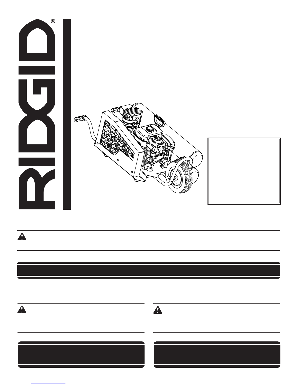
8 GALLON PORTABLE AIR COMPRESSOR
COMPRESSEUR D’AIR PORTABLE
DE 30,3 LITRES (8 GALLONS)
COMPRESOR DE AIRE PORTÁTIL
DE 30,3 LITROS (8 GALONES)
GP80145SW
To register your RIDGID
product, please visit:
http://register.RIDGID.com
Pour enregistrer votre
produit de RIDGID,
s’il vous plaît la visite :
http://register.RIDGID.com
Para registrar su producto
de RIDGID, por favor visita:
http://register.RIDGID.com
Your air compressor has been engineered and manufactured to our high standard for dependability, ease of operation, and
operator safety. When properly cared for, it will give you years of rugged, trouble-free performance.
WARNING:
To reduce the risk of injury, the user must read and understand the operator’s manual before using this product.
Thank you for buying a RIDGID® product.
SAVE THIS MANUAL FOR FUTURE REFERENCE
Ce compresseur d’air a été conçu et fabriqué conformément
aux strictes normes de fiabilité, simplicité d’emploi et sécurité
d’utilisation. Correctement entretenu, il vous donnera des années
de fonctionnement robuste et sans problème.
AVERTISSEMENT :
Pour réduire les risques de blessures, l’utilisateur doit
lire et veiller à bien comprendre le manuel d’utilisation
avant d’employer ce produit.
Su compresor de aire ha sido diseñado y fabricado de conformidad
con las estrictas normas para brindar fiabilidad, facilidad de uso
y seguridad para el operador. Con el debido cuidado, le brindará
muchos años de sólido y eficiente funcionamiento.
ADVERTENCIA:
Para reducir el riesgo de lesiones, el usuario debe leer
y comprender el manual del operador antes de usar
este producto.
Merci d’avoir acheté un produit RIDGID®.
CONSERVER CE MANUEL POUR
FUTURE RÉFÉRENCE
Le agradecemos la compra de un producto RIDGID®.
GUARDE ESTE MANUAL PARA
FUTURAS CONSULTAS
TABLE OF CONTENTS
Introduction.......................................................................................................................................................................2
General Safety Rules .....................................................................................................................................................3-4
Specific Safety Rules ........................................................................................................................................................5
Symbols ............................................................................................................................................................................ 6
Glossary of Terms ............................................................................................................................................................. 7
Features ............................................................................................................................................................................ 8
Assembly .......................................................................................................................................................................8-9
Operation .....................................................................................................................................................................9-12
Maintenance ..............................................................................................................................................................13-15
Troubleshooting .............................................................................................................................................................. 16
Warranty ....................................................................................................................................................................17-18
Figure numbers (illustrations) .....................................................................................................................................19-22
Customer Service Information ...........................................................................................................................Back Page
INTRODUCTION
This product has many features for making its use more pleasant and enjoyable. Safety, performance, and dependability
have been given top priority in the design of this product making it easy to maintain and operate.
DANGER:
This compressor/pump is not equipped and should not be used to supply breathing quality air. Additional equipment would be necessary to properly filter and purify the air to meet minimal specifications for Grade D breathing
as described in Compressed Gas Association Commodity Specification G 7.1 - 1966, OSHA 29 CFR 1910.134.
Compressed Gas Association, 4221 Walney Road, Fifth Floor, Chantilly, VA 20151-2923, (703) 788-2700,
www.cganet.com. Any such additional equipment has not been examined and no implication of proper use for
breathing air is intended or implied.
If this compressor is altered in any way, existing warranties shall be voided. RIDGID® and One World Technologies,
Inc. disclaim any liabilities whatsoever for any loss, personal injury, or damage.
DISCLAIMER OF WARRANTIES
In the event the compressor is used for the purpose of breathing air application and proper in-line safety and alarm
equipment is not simultaneously used, existing warranties shall be voided, and RIDGID® disclaims any liabilities
whatsoever for any loss, personal injury, or damage.
California Proposition 65
WARNING:
This product and some dust created by power sanding, sawing, grinding, drilling, and other construction activities
may contain chemicals, including lead, known to the State of California to cause cancer, birth defects, or other
reproductive harm. Wash hands after handling.
Some examples of these chemicals are:
• leadfromlead-basedpaints,
• crystallinesilicafrombricksandcementandothermasonryproducts,and
• arsenicandchromiumfromchemically-treatedlumber.
Your risk from exposure to these chemicals varies, depending on how often you do this type of work. To reduce
your exposure, work in a well-ventilated area and with approved safety equipment, such as dust masks that are
specially designed to filter out microscopic particles.
2 – English

GENERAL SAFETY RULES
WARNING:
Read and understand all instructions. Failure
to follow all instructions listed below may result
in electric shock, fire and/or carbon monoxide
poisoning which will cause death or serious
personal injury.
SAVE THESE INSTRUCTIONS
Do not overreach. Keep proper footing and balance
at all times. Proper footing and balance enables better
control of the product in unexpected situations.
Use safety equipment. Always wear eye protection.
Dust mask, nonskid safety shoes, hard hat, or hearing
protection must be used for appropriate conditions.
Do not use on a ladder or unstable support. Stable
footing on a solid surface enables better control of the
air compressor in unexpected situations.
WORK AREA
Keep your work area clean and well lit. Cluttered
benches and dark areas invite accidents. Floor must not
be slippery from wax or dust.
Do not operate air compressors in explosive atmo-
spheres, such as in the presence of flammable liquids,
gases, or dust. Air compressors create sparks which may
ignite the dust or fumes.
Keep bystanders, children, and visitors away while
operating an air compressor. Distractions can cause you
to lose control.
Operate air compressor in an open area at least 18 in.
away from any wall or object that could restrict the
flow of fresh air to ventilation openings.
PERSONAL SAFETY
Always wear eye protection with side shields marked
to comply with ANSI Z87.1 as well as hearing protection when operating this equipment.
The employer and/or user must ensure that proper
eye protection is worn. We recommend a Wide Vision
Safety Mask for use over eyeglasses or standard safety
glasses that provide protection against flying particles
both from the front and side. Always use eye protection
which is marked to comply with ANSI Z87.1.
Additional safety protection will be required in some
environments. For example, the working area may
include exposure to a noise level which can lead to hearing damage. The employer and user must ensure that any
necessary hearing protection is provided and used by the
operator and others in the work area. Some environments
will require the use of head protection equipment. When
required, the employer and user must ensure that head
protection marked to comply with ANSI Z89.1 is used.
Stay alert, watch what you are doing, and use com-
mon sense when operating the air compressor. Do
not use product while tired or under the influence of
drugs, alcohol, or medication. A moment of inattention
while operating an air compressor may result in serious
personal injury.
Dress properly. Do not wear loose clothing or jewelry.
Contain long hair. Keep your hair, clothing, and gloves
away from moving parts. Loose clothes, jewelry, or long
hair can be caught in moving parts.
AIR COMPRESSOR USE AND CARE
For outdoor use only.
Do not exceed the pressure rating of any component
in the system.
Protect material lines and air lines from damage or
puncture. Keep hose away from sharp objects, chemical
spills, oil, solvents, and wet floors.
Check hoses for weak or worn condition before each
use, making certain all connections are secure. Do not
use if defect is found. Purchase a new hose or notify an
authorized service center for examination or repair.
Release all pressures within the system slowly. Dust
and debris may be harmful.
Store idle air compressors out of the reach of children
and other untrained persons. Air compressors are dan-
gerous in the hands of untrained users.
Maintain air compressors with care. Follow mainte-
nance instructions. Properly maintained products are
easier to control.
Check for misalignment or binding of moving parts,
breakage of parts, and any other condition that may
affect the product’s operation. If damaged, have the
air compressor serviced before using. Many accidents
are caused by poorly maintained products.
Keep the exterior of the air compressor dry, clean, and
free from oil and grease. Always use a clean cloth when
cleaning. Never use brake fluids, gasoline, petroleumbased products, or any strong solvents to clean the unit.
Following this rule will reduce the risk of deterioration of
the enclosure plastic.
Keep the engine free of grass, leaves, or grease to
reduce the chance of a fire hazard.
Keep guards in place and in working order. Never oper-
ate the tool with any guard or cover removed. Make sure
all guards are operating properly before each use.
Do not operate the engine in a confined space where
dangerous carbon monoxide fumes can collect. Carbon
monoxide, a colorless, odorless, and extremely dangerous gas, can cause unconsciousness or death.
Keep the exhaust pipe free of foreign objects.
Do not operate around dry brush, twigs, cloth rags, or
other flammable materials.
3 – English

GENERAL SAFETY RULES
Never pick up or carry a machine while the engine is
running.
Never start the machine if ice has formed in any part
of the equipment.
Always operate the machine on a level surface. If the
engine is on an incline, it could seize due to improper
lubrication (even at the maximum oil level).
Never attempt to make any adjustments while the
engine (motor) is running (except where specifically
recommended by the manufacturer).
Protective covers must always cover rotating parts
when the engine is running.
Keep cooling air intake (recoil starter area) and muffler
side of the engine at least 3 feet away from buildings,
obstructions, and other combustible objects.
Keep the engine away from flammables and other
hazardous materials.
Keep away from hot parts. The muffler and other engine
parts become very hot; use caution.
Do not touch the spark plug and ignition cable when
starting and operating the engine.
Check fuel hoses and joints for looseness and fuel
leakage before each use.
Check bolts and nuts for looseness before each use.
A loose bolt or nut may cause serious engine problems.
Always refuel outdoors. Never refuel indoors or in a
poorly ventilated area.
Never store the machine with fuel in the fuel tank
inside a building where ignition sources are present,
such as hot water and space heaters, clothes dryers,
and the like.
If the fuel tank has to be drained, do this outdoors.
To reduce the risk of fire and burn injury, handle fuel
with care. It is highly flammable.
Do not smoke while handling fuel.
Add fuel before starting the engine. Never remove the
cap of the fuel tank or add fuel while the engine is running
or when the engine is hot.
Loosen fuel cap slowly to release pressure and to keep
fuel from escaping around the cap.
Replace all fuel tank and container caps securely.
Wipe spilled fuel from the unit. Move 30 feet away from
refueling site before starting engine.
If fuel is spilled, do not attempt to start the engine but
move the machine away from the area of spillage and
avoid creating any source of ignition until fuel vapors
have dissipated.
Never attempt to burn off spilled fuel under any
circumstances.
Before storing, allow the engine to cool.
Store fuel in a cool, well-ventilated area, safely away
from spark and/or flame-producing equipment.
Store fuel in containers specifically designed for this
purpose.
Empty fuel tank and restrain the unit from moving
before transporting in a vehicle.
Make sure minimum clearance of 3 feet is maintained
from combustible materials.
SERVICE
When servicing a product, use only identical
replacement parts. Follow instructions in the
Maintenance section
parts or failure to follow Maintenance instructions may
create a risk of injury.
Service must be performed only by qualified repair
personnel. Service or maintenance performed by
unqualified personnel may result in a risk of injury.
Disconnect the spark plug wire, open drain valve to
decompress tanks and allow water to drain, and allow
air compressor to become cool to the touch before
servicing. Turn pressure regulator knob fully clockwise
after shutting off air compressor.
of this manual. Use of unauthorized
4 – English

SPECIFIC SAFETY RULES
Know your air compressor. Read operator’s manual
carefully. Learn its applications and limitations, as well
as the specific potential hazards related to this product.
Following this rule will reduce the risk of electric shock,
fire, or serious injury.
Drain tanks of moisture after each day’s use. If unit will
not be used for a while, it is best to leave drain valve open
until such time as it is to be used. This will allow moisture
to completely drain out and help prevent corrosion on the
inside of tanks.
Risk of Fire or Explosion. Do not spray flammable liquid
in a confined area. Spray area must be well ventilated. Do
not smoke while spraying or spray where spark or flame
is present. Keep compressors as far from the spraying
area as possible, at least 15 feet from the spraying area
and all explosive vapors.
Risk of Bursting. Do not adjust regulator to result in
output pressure greater than marked maximum pressure of
attachment. Do not use at pressure greater than 145 psi.
Inspect tanks yearly for rust, pin holes, or other
imperfections that could cause it to become unsafe.
Never weld or drill holes in the air tanks.
Make sure the hose is free of obstructions or snags.
Entangled or snarled hoses can cause loss of balance or
footing and may become damaged.
Use the air compressor only for its intended use. Do
not alter or modify the unit from the original design
or function.
Always be aware that misuse and improper handling of
this product can cause injury to yourself and others.
Never leave a tool unattended with the air hose
attached.
Never point any air tool toward yourself or others.
Do not operate this air compressor if it does not
contain a legible warning label.
Do not continue to use a tool or hose that leaks air or
does not function properly.
Always disconnect the air supply and remove spark
plug wire before making adjustments, servicing a
product, or when a product is not in use.
Do not attempt to pull or carry the air compressor by
the hose.
Your tool may require more air consumption than this
air compressor is capable of providing.
Always follow all safety rules recommended by the
manufacturer of your air tool, in addition to all safety
rules for the air compressor. Following this rule will
reduce the risk of serious personal injury.
Never direct a jet of compressed air toward people or
animals. Take care not to blow dust and dirt towards
yourself or others. Following this rule will reduce the risk
of serious injury.
Do not use this air compressor to spray chemicals.
Your lungs can be damaged by inhaling toxic fumes. A
respirator may be necessary in dusty environments or
when spraying paint. Do not carry while painting.
Inspect hoses periodically and, if damaged, have
repaired at your nearest Authorized Service Center.
Check damaged parts. Before further use of the air
compressor or air tool, a guard or other part that is
damaged should be carefully checked to determine
that it will operate properly and perform its intended
function. Check for alignment of moving parts, binding
of moving parts, breakage of parts, mounting, and
any other conditions that may affect its operation. A
guard or other part that is damaged should be properly
repaired or replaced by an authorized service center.
Following this rule will reduce the risk of shock, fire, or
serious injury.
Never store a tool with air connected. Storing the tool
with air connected can result in unexpected firing and
possible serious personal injury.
Protect your lungs. Wear a face or dust mask if the
operation is dusty. Following this rule will reduce the risk
of serious personal injury.
Save these instructions. Refer to them frequently and use
them to instruct others who may use this product. If you
loan someone this product, loan them these instructions
also.
5 – English
SYMBOLS
The following signal words and meanings are intended to explain the levels of risk associated with this product.
SYMBOL SIGNAL MEANING
DANGER:
WARNING:
CAUTION:
CAUTION:
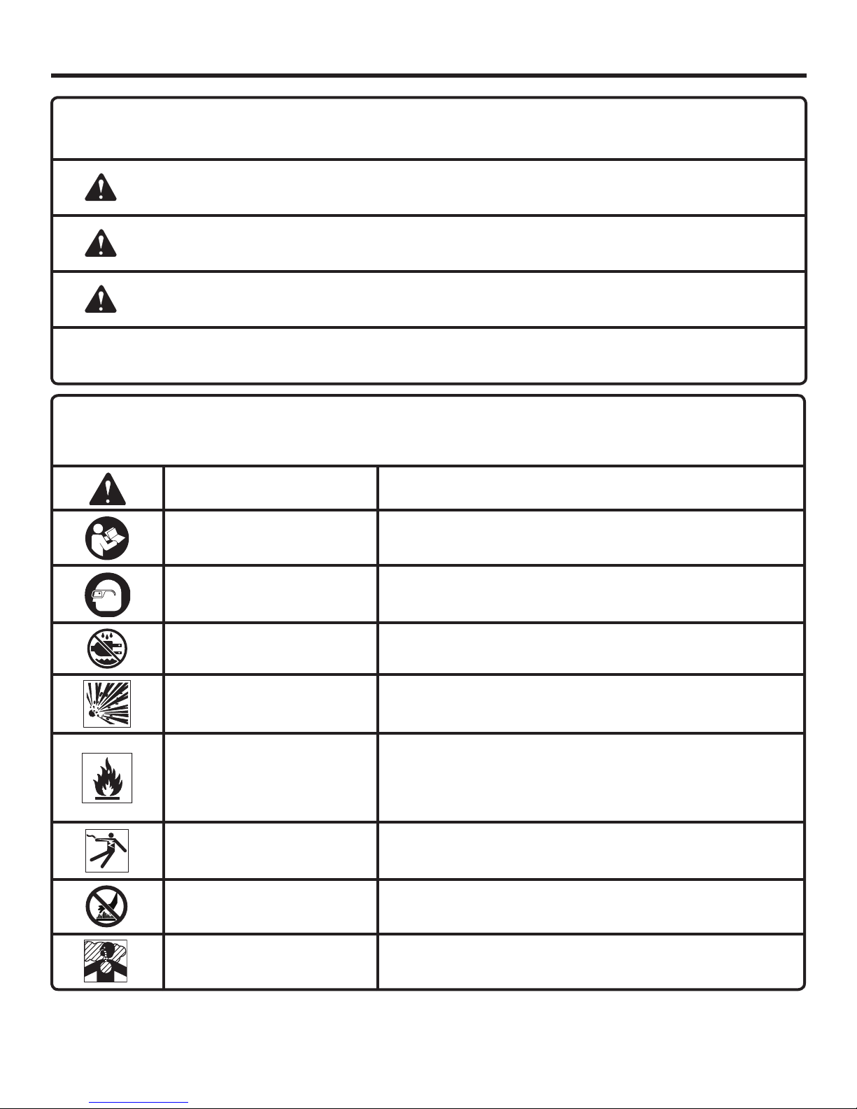
Some of the following symbols may be used on this product. Please study them and learn their meaning. Proper
interpretation of these symbols will allow you to operate the product better and safer.
SYMBOL NAME
Safety Alert Indicates a potential personal injury hazard.
Read Operator’s Manual
Indicates an imminently hazardous situation, which, if not avoided, will result
in death or serious injury.
Indicates a potentially hazardous situation, which, if not avoided, could result
in death or serious injury.
Indicates a potentially hazardous situation, which, if not avoided, may result in
minor or moderate injury.
(Without Safety Alert Symbol) Indicates a situation that may result in property
damage.
DESIGNATION/EXPLANATION
To reduce the risk of injury, user must read and understand
operator’s manual before using this product.
Eye Protection
Wet Conditions Alert Do not expose to rain or use in damp locations.
Risk of Bursting
Risk of Fire or Explosion
Risk of Electrical Shock
Hot Surface
Risk to Breathing
Always wear eye protection with side shields marked to comply
with ANSI Z87.1.
Do not adjust regulator to result in output pressure greater than
marked maximum pressure of attachment. Do not use at pressure
greater than 145 PSI.
Do not spray flammable liquid in a confined area. Spray area must
be well ventilated. Do not smoke while spraying or spray where
spark or flame is present. Keep compressors as far from the spraying area as possible, at least 15 feet from the spraying area and
all explosive vapors.
Failure to use in dry conditions and to observe safe practices can
result in electric shock.
To reduce the risk of injury or damage, avoid contact with any hot
surface.
Air obtained directly from the air compressor should never be used
to supply air for human consumption.
6 – English

GLOSSARY OF TERMS
Air Filter
Porous element contained within a metal or plastic housing
attached to the compressor cylinder head which removes
impurities from the intake air of the compressor.
Air Tank
Cylindrical component which contains the compressed air.
Belt Guard
Protects the operator from coming in contact with the belt
and rotating pulleys.
Cut-In Pressure
The low pressure at which the engine speed will automatically
increase to full speed.
Cut-Off Pressure
The high pressure at which the engine speed will automatically
decrease to idle speed.
NPT (National Pipe Thread)
A seal thread tape must be used to provide a leak-free seal
on pipe threaded connections.
Pressure Regulator Knob
Regulates the outgoing pressure from the air outlet to the
tool. It is possible to increase or decrease the pressure at
the outlet by adjusting this control knob.
Pressure Unloader
Automatically controls the speed of the compressor's engine.
The engine runs at idle speed when the cut-off pressure in
the tank is reached and switches the engine to full speed
once the pressure drops below the cut-in pressure.
PSI (Pounds Per Square Inch)
Measurement of the pressure exerted by the force of the
air. The actual psi is measured by a pressure gauge on the
compressor.
Pump
Produces the compressed air with a reciprocating piston
contained within the cylinder.
Quick Connect Couplers
The 1/4 in. quick connect couplers allow the operator to
easily attach air hoses to the compressor.
Outlet pressure gauge
Displays the current line pressure. Line pressure is adjusted
by rotating the pressure regulator knob.
Safety valve
Prevents air pressure in the air tank from rising over a
predetermined limit.
SCFM (Standard Cubic Feet Per Minute) or CFM (Cubic
Feet Per Minute)
A unit of measure of air delivery.
Tank Pressure Gauge
Indicates the pressure in the air tank.
7 – English

FEATURES
PRODUCT SPECIFICATIONS
Air Tank Capacity .......................................................8 gal.
Air Pressure .................................................... 145 psi max.
Air Delivery .........................................10.2 SCFM @ 90 psi
Engine..............................................................170 cc OHC
Gauges ..........................................................2 in. diameter
Net Weight .............................................................. 194 lbs.
KNOW YOUR AIR COMPRESSOR
See Figures 1a and 1b, page 19.
The safe use of this product requires an understanding of the
information on the product and in this operator’s manual as
well as a knowledge of the project you are attempting.Before
use of this product, familiarize yourself with all operating
features and safety rules.
CHOKE LEVER
The choke lever is used when starting the engine.
DRAIN VALVE
The drain valve on the tank is for draining condensation to
help prevent tank corrosion.
ENGINE
The engine enables the air compressor to achieve 10.2
SCFM at 145 psi. Please read the engine manual included
with this product.
ENGINE OIL CAP/DIPSTICK
Remove the engine oil cap/dipstick to check and add oil to
the engine when necessary.
ON/STOP SWITCH
The on/stop switch is used in combination with the recoil
starter to start the air compressor. It is also used to turn the
air compressor off.
HANDLES
The air compressor is equipped with handles for easy
transport.
PRESSURE REGULATOR KNOB
Use the pressure regulator knob to adjust the amount of
air being delivered through the hose. Pressing down on the
knob will lock it into place. This prevents movement of the
knob caused by vibration during use.
PUMP OIL CAP/DIPSTICK
Remove the pump oil cap/dipstick to check and add oil to
the pump when necessary.
OUTLET PRESSURE GAUGE
The current line pressure is displayed on the regulator
pressure gauge. This pressure can be adjusted by rotating
the pressure regulator knob.
RECOIL STARTER
The recoil starter is pulled to start the machine.
TANK PRESSURE GAUGE
The tank pressure gauge indicates the pressure of the air
in the tank.
QUICK CONNECT COUPLERS
Your air compressor has two 1/4 in. quick connect couplers
located on the control panel.
ASSEMBLY
UNPACKING
This product requires assembly.
Carefully remove the product and any accessories from
the box. Make sure that all items listed in the packing list
are included.
NOTE: This tool is heavy. To avoid back injury, lift with
your legs, not your back, and get help when needed.
WARNING:
Do not use this product if any parts on the Packing
List are already assembled to your product when
you unpack it. Parts on this list are not assembled
to the product by the manufacturer and require
customer installation. Use of a product that may
have been improperly assembled could result in
serious personal injury.
Inspect the product carefully to make sure no breakage
or damage occurred during shipping.
Do not discard the packing material until you have care-
fully inspected and satisfactorily operated the product.
If any parts are damaged or missing, please call
1-800-474-3443 for assistance.
PACKING LIST
Air Compressor
4-Cycle Engine Oil (SAE 30 or SAE 10W30)
Axle Rod
Handles (2)
Hitch Pins (2)
Lock Washers (4)
Long Screws (2)
Axle Bolts (2)
Pump Oil (SAE40)
Semi-pneumatic Tire
Short Screws (2)
Washers (4)
Spark Plug Wrench
Operator’s Manual
8 – English
ASSEMBLY
TOOLS NEEDED
See Figure 2, page 19.
The following tools (not included or drawn to scale) are
needed for assembly:
Adjustable Wrench
Phillips Screwdriver
WARNING:
If any parts are damaged or missing do not operate
this product until the parts are replaced. Use of
this product with damaged or missing parts could
result in serious personal injury.
WARNING:
Do not attempt to modify this product or create
accessories not recommended for use with this
product. Any such alteration or modification is
misuse and could result in a hazardous condition
leading to possible serious personal injury.
WARNING:
To prevent accidental starting that could cause
serious personal injury, always disconnect the
engine spark plug wire from the spark plug when
assembling parts.
INSTALLING THE HANDLES
See Figure 3, page 20.
Insert supplied handle through handle slot.
Slide handle forward until the hole in the handle is aligned
with the first hole in the handle slot.
Place a washer and lock washer onto long screw. Then
install long screw through the hole in the handle.
Place a washer and lock washer onto short screw. Then
install short screw through the second hole in the handle slot.
Repeat handle installation on the opposite side.
INSTALLING OIL CAP/DIPSTICK
See Figure 4, page 20.
The air compressor has a label installed between the pump
oil cap/dipstick and the oil fill hole. Before using the unit the
first time, remove the pump oilcap/dipstick and label and
then reinsert dipstick. Make sure to add oil before first use.
See Adding/Checking Pump Oil before first time operation.
INSTALLING THE SEMI-PNEUMATIC TIRE
See Figure 5, page 20.
Insert supplied axle rod through hole in semi-pneumatic
tire hub, centering the tire between the two center holes
in the axle rod.
Slide hitch pins through both holes on either side of semi-
pneumatic tire to secure semi-pneumatic tire to the center
of the axle rod.
Place tire assembly in the center of the wheel brace as
shown.
Align the threaded holes on the tire assembly with the
holes on the left and right side of the wheel brace. Install
supplied Phillips head screws through the lined up holes.
OPERATION
DANGER:
Do not disassemble pressure unloader, tank drain
valves or safety relief valve with air in tank — bleed
tanks.
WARNING:
Do not allow familiarity with products to make you
careless. Remember that a careless fraction of a
second is sufficient to inflict severe injury.
WARNING:
Always wear eye protection with side shields
marked to comply with ANSI Z87.1. Failure to do
so could result in objects being thrown into your
eyes resulting in possible serious injury.
WARNING:
Neverdirectajetofcompressedairtowardpeople
or animals. Take care not to blow dust and dirt
towards yourself or others. Following this rule will
reduce the risk of serious injury.
CAUTION:
Do not use in an environment that is dusty or
otherwise contaminated. Using the air compressor
in this type of environment may cause damage to
the unit.
APPLICATIONS
Air compressors are utilized in a variety of air system
applications. Match hoses, connectors, air tools, and
accessories to the capabilities of the air compressor.
9 – English
OPERATION
You may use this product for the purposes listed below:
Operating some air-powered tools
Operating air accessories such as air nozzles and tire
inflators
ADDING/CHECKING ENGINE OIL
See Figures 6 - 7, page 20.
NOTE: This machine has been shipped with approximately
2 oz. of oil in the engine from testing. You must add oil to
the engine before starting it the first time.
CAUTION:
Any attempt to start the engine without adding oil
will result in engine failure.
To add engine oil:
Place air compressor on a flat, level surface.
Unscrew the engine oil cap/dipstick by turning counter-
clockwise.
Before first use, pour the entire contents of the oil bottle
provided into the oil reservoir.
After initial use, add 4-stroke engine oil (SAE 30 or SAE
10W30) until the fluid level rises between the hatched
area on the dipstick. Do not overfill.
NOTE: Avoid using too much oil. Ensure that the level of
the oil does not rise above the upper hatched area.
Replace the engine oil cap/dipstick and securely tighten.
NOTE: This engine has a total oil capacity of 20 oz. (0.6 liters).
To check engine oil level:
Set engine on a flat surface.
Remove engine oil cap/dipstick.
Wipe engine oil cap/dipstick clean and re-seat in hole.
Do not rethread.
Remove engine oil cap/dipstick again and check oil level. Oil
level should be between the hatched area on the dipstick.
If level is low, add engine oil until the fluid level rises to
the upper portion of the hatched area on the dipstick.
Replace and secure the engine oil cap/dipstick
ADDING/CHECKING PUMP OIL
See Figure 8, page 20.
Unscrew the pump oil cap/dipstick by turning counter-
clockwise.
Before first use, pour the entire contents of the pump oil
bottle provided into the oil reservoir.
After initial use, add pump oil until the fluid level rises
between the MIN and MAX reference levels on the
dipstick. Do not overfill.
NOTE: Avoid using too much oil. Ensure that the level of
the oil does not exceed the maximum reference level on
the dipstick.
Replace the pump oil cap/dipstick and securely tighten.
NOTE: This pump has a total oil capacity of 30 oz. (887.2ml).
ADDING GASOLINE TO THE FUEL TANK
See Figure 9, page 20.
WARNING:
Gasoline and its vapors are highly flammable and
explosive. To prevent serious personal injury and
property damage, handle gasoline with care. Keep
away from ignition sources, handle outdoors only,
do not smoke while adding fuel, and wipe up spills
immediately.
When adding gas to the air compressor, make sure the unit
is sitting on a flat, level surface. If the engine is hot, let the
air compressor cool before adding gas. ALWAYS fill the fuel
tank outdoors with the machine turned off.
NOTE: Use unleaded gas only. DO NOT mix oil with gas.
Before removing the fuel cap, clean the area around it.
Remove the fuel cap.
Insert a clean funnel into the fuel tank then slowly
pour gasoline into the tank. Fill tank to approximately
1-1/2 in. below the top of the tank neck (this allows for
fuel expansion).
Replace fuel cap and tighten securely.
Clean up any spills before starting the engine.
CAUTION:
Do not overfill. Overfilling the crankcase may cause
excessive smoke and engine damage.
OXYGENATED FUELS
DO NOT USE E85 FUEL. IT WILL VOID YOUR WARRANTY.
NOTE: Fuel system damage or performance problems
resulting from the use of an oxygenated fuel containing more
than the percentages of oxygenates stated below are not
covered under warranty.
Ethanol. Gasoline containing up to 10% ethanol by volume
(commonly referred to as E10) is acceptable. E85 is not.
WARNING:
Always shut off engine before fueling. Never add
fuel to a machine with a running or hot engine.
Move at least 30 ft. from refueling site before
starting engine. Do not smoke and stay away from
open flames and sparks! Failure to follow these
instructions could result in serious personal injury.
ATTACHING/DISCONNECTING A HOSE
See Figure 10, page 20.
Make sure the air compressor is off.
Rotate pressure regulator knob fully counterclockwise.
10 – English
OPERATION
Attach hose with quick connect air fitting to 1/4 in. quick
coupler on air compressor. Make sure to push the hose
adapter end fully into the coupler until the sleeve springs
forward to lock it in place.
To disconnect an air hose or an air tool:
Make sure the air compressor is off and confirm that the
outlet pressure is at zero (0) psi.
When disconnecting a hose from 1/4-in. quick coupler,
always firmly hold release end of hose.
Pull back on the release sleeve on the 1/4-in. quick
coupler.
With a firm grip, pull out the quick-connect air fitting that
is attached to the quick coupler.
BREAK-IN PERIOD
Before first use, run the air compressor at zero tank pressure
with the drain valves fully open for 30 minutes.
CAUTION:
On a level surface with the engine off, check the
pump and engine oil levels before each use of the
compressor.
STARTING AND STOPPING THE AIR
COMPRESSOR
See Figures 11 - 14, pages 20 and 21
Before starting the engine:
Connect all hoses.
Check all fluids (oil and gas).
To start the engine:
Turn the fuel valve to the ON position.
Move the choke lever to the START position.
NOTE: If the engine is warm, leave the choke lever in the
RUN position.
Put the on/stop switch in the ON position.
Grasp the recoil starter and pull slowly until resistance is
felt. Give the recoil starter a short, brisk pull to start the
engine (no more than 4 pulls).
NOTE: Do not allow the recoil starter to snap back after
starting; return it gently to its original place.
NOTE: If the engine fails to start, wait several minutes
then repeat the above steps as needed.
Allow the engine to run for 30 seconds, then move the
choke lever to the RUN position.
NOTE: Once the air compressor is started, pressure
inside the air tank will build until the compressor reaches
145 psi. After reaching maximum tank pressure the
engine will idle allowing the pressure inside the air tank to
decrease until it reaches a preset level. When the pressure
falls below the preset level, the engine will accelerate and
provide additional air pressure.
To stop the engine:
Put the on/stop switch in the OFF position.
WARNING:
The pump exhaust tube will become hot during
use. Avoid contact with the pump exhaust tube
when stopping the engine.
Turn the fuel valve to the OFF position.
WARNING:
Never exceed the air tool’s pressure rating as
recommended by the manufacturer. When using
this air compressor as an inflation device, always
follow the maximum inflation guidelines stated by
the manufacturer of the item being inflated.
WARNING:
Always ensure the on/stop switch is in the OFF (O)
position and the outlet pressure gauge reads zero
before changing air tools or disconnecting the hose
from the air outlet. Failure to do so could result in
possible serious personal injury.
USING THE AIR COMPRESSOR
See Figures 15 - 16, page 21.
Check all fluids (oil and gas).
Turn off the air compressor.
If not already installed, attach hose to compressor as
previously instructed.
Attach 1/4 in. NPT quick-connect air fitting to accessory
or tool you intend to use.
Insert the other end of the quick-connect air fitting to the
quick coupler on the open end of hose.
Start the air compressor.
Pull out and rotate pressure regulator knob to desired
line pressure. Turning the knob clockwise increases air
pressure at the outlet; turning counterclockwise reduces
air pressure at the outlet.
Following all safety precautions in this manual and the
manufacturer’s instructions in the air tool manual, you
may now proceed to use your air-powered tool.
WARNING:
Air powered tools may require more air consumption
than this air compressor is capable of providing.
Check the tool manual to avoid damage to the tool
or risk of personal injury.
11 – English
OPERATION
Control the amount of air flow with the pressure regulator
knob. Turning the knob fully counterclockwise will
completely stop the flow of air.
NOTE: Always use the minimum amount of pressure
necessary for your application. Using a higher pressure
than needed will drain air from the tank more rapidly and
cause the unit to cycle on more frequently.
When finished, always stop the engine and drain the tank.
Never leave the unit running unattended.
DRAINING THE AIR TANK
See Figures 17 - 18, page 21.
To help prevent tank corrosion and keep moisture out of the
air used, the air tank of the compressor should be drained
daily.
To drain:
Turn off the air compressor.
Pull the ring on the pressure relief valve to release air
pressure. Continue venting until pressure gauge reads
less than 20 psi.
Release the ring.
Rotate drain valve counterclockwise to open.
Tilt tank to drain moisture from tank into a suitable
container.
NOTE: This tool is heavy. To avoid back injury, lift with
your legs, not your back, and get help when needed.
NOTE: Condensate is a polluting material and should be
disposed of in compliance with local regulations.
If drain valves are clogged, release all air pressure, remove
and clean valves, then reinstall.
WARNING:
Turn off the air compressor and release all air from
the tank before servicing. Failure to depressurize
tank before attempting to remove valve may cause
serious personal injury.
Rotate drain valve clockwise until tightly closed.
MOVING THE AIR COMPRESSOR
Turn the air compressor off.
Tilt the machine away from you until it balances on the
wheel then roll the machine to the desired position.
Allow 30 minutes of “cool down” time before storing the
machine.
12 – English
MAINTENANCE
WARNING:
When servicing use only identical RIDGID®
replacement parts. Use of any other parts may
create a hazard or cause product damage.
WARNING:
Always wear eye protection with side shields
marked to comply with ANSI Z87.1. Failure to do
so could result in objects being thrown into your
eyes resulting in possible serious injury.
WARNING:
Before inspecting, cleaning or servicing the
machine, shut off engine, wait for all moving parts
to stop, and disconnect spark plug wire and move
it away from spark plug. Failure to follow these
instructions can result in serious personal injury
or property damage.
GENERAL MAINTENANCE
Avoid using solvents when cleaning plastic parts. Most
plastics are susceptible to damage from various types of
commercial solvents and may be damaged by their use. Use
clean cloths to remove dirt, dust, oil, grease, etc.
As a routine part of air compressor maintenance, it is also
advised that the oil is routinely checked for proper levels.
Pull the ring on the safety valve to release air for three to
five seconds.
The ring pin must be pushed back into position to stop
the flow of air at high pressure.
WARNING:
If air leaks after the ring has been released, or if the
valve is stuck and cannot be actuated by the ring,
do not use the air compressor until the safety valve
has been replaced. Use of the air compressor in
this condition could result in serious personal injury.
CLEANING EXHAUST PORT AND MUFFLER
Depending on the type of fuel used, the type and
amount of oil used, and/or your operating conditions, the
exhaust port and/or muffler may become blocked with
carbon deposits. If you notice a power loss with your gas
powered tool, you may need to remove these deposits to
restore performance. We highly recommend that only qualified service technicians perform this service.
REPLACING THE SEMI-PNEUMATIC TIRE
Turn off the air compressor.
Remove the screws installed through the tire assembly
and the holes on the left and right side of the wheel brace.
Remove the tire assembly.
Remove hitch pins on either side of semi-pneumatic tire.
Remove semi-pneumatic tire.
To install new semi-pneumatic tire, see Installing the
Semi-Pneumatic Tire in Assembly.
WARNING:
Do not at any time let brake fluids, gasoline,
petroleum-based products, penetrating oils, etc.,
come in contact with plastic parts. Chemicals can
damage, weaken or destroy plastIc which may
result in serious personal injury.
CHECKING THE SAFETY VALVE
See Figure 17, page 21.
WARNING:
Do not attempt to tamper with the safety valve.
Anything loosened from this device could fly up
and hit you. Failure to heed this warning could
result in death or serious personal injury.
The safety valve will automatically release air if the air tank
pressure exceeds the preset maximum. The valve should be
checked before each day of use by pulling the ring by hand.
Start the air compressor and allow the tank to fill. The
compressor will idle when the pressure reaches the preset
maximum.
Turn off the air compressor.
CLEANING THE PUMP AIR FILTER
See Figure 19, page 21.
Turn off the air compressor.
With one hand, secure the pump air filter cover. With the
other hand, remove the hex bolts and washers securing
the cover.
Remove the cover.
Remove the air filter from the cover.
Wash the air filter with warm, soapy water.
Rinse and squeeze to dry.
Reinstall the air filter.
Place the air filter cover back on the unit. Reinstall hex
bolts and washers. Tighten to secure.
CLEANING THE ENGINE AIR FILTER
See Figure 20, page 21.
A dirty air filter will cause starting difficulty, loss of
performance, and shorten the life span of the engine. Check
the air filter monthly. For best performance, replace the air
filter at least once a year.
Turn off the air compressor.
Push the tab on the air filter cover to open, then remove
the air filter cover.
13 – English

MAINTENANCE
Lift the edge of the air filter carefully and pull it out.
Wash the air filter with warm, soapy water.
Rinse and squeeze to dry.
Put small amount of motor oil (SAE 30, or SAE 10W30) on
the filter sponge. Squeeze out the excess oil then reinstall
the air filter.
NOTE: Make sure the filter is seated properly inside the
cover. Installing the filter incorrectly will allow dirt to enter
the engine, causing rapid engine wear.
Reinstalltheairfiltercover.
CHANGING THE ENGINE OIL
See Figure 21, page 22.
Replace the engine oil after the first 100 hours of operation
and every 100 hours following the first oil change.
Turn off the air compressor.
Place a suitable container underneath the drain hole to
collect used oil.
Remove the drain plug with an adjustable wrench.
When the used oil has drained, reinstall the drain plug
and tighten with the wrench.
Remove the engine oil cap/dipstick.
To refill, use a funnel to pour oil into the fill hole. Refill
only with 4-stroke engine oil (SAE 30 or SAE 10W30).
NOTE: Avoid refilling with too much oil. Ensure that the
level of the oil does not exceed the maximum reference
level on the dipstick. The recommended amount of oil for
refilling is 16 oz. (0.47 liters).
Reinsert the oil cap/dipstick securely into the oil fill hole.
NOTE: Consult hazardous waste management guidelines in
your area for the proper way to dispose of used oil.
SPARK PLUG MAINTENANCE
See Figure 22, page 22.
The spark plug must be properly gapped and free of deposits
to ensure proper engine operation. To check:
Turn off the air compressor.
Remove the spark plug cap.
Clean any dirt from around base of spark plug.
Remove spark plug using an adjustable wrench (not
included).
Inspect spark plug for damage, and clean with a wire
brush before reinstalling. If insulator is cracked or
chipped, spark plug should be replaced.
NOTE: If replacing, use the following recommended
spark plug or equivalent: Champion RL87YC.
Measureplug gap.Thecorrectgapis0.023−0.027 in.
(0.6 mm - 0.7 mm). To widen gap, if necessary, carefully
bend the ground (top) electrode. To lessen gap, gently
tap ground electrode on a hard surface.
Seat spark plug in position; thread in by hand to prevent
cross-threading.
Tighten with an adjustable wrench to compress washer.
If spark plug is new, use 1/2 turn to compress washer
appropriate amount. If reusing old spark plug, use 1/8 to
1/4 turn for proper washer compression.
NOTE: An improperly tightened spark plug will become
very hot and could damage the engine.
CHANGING THE PUMP OIL
See Figure 23, page 22.
Turn off the air compressor.
Raise the air compressor high enough to gain access to
the drain valve; securely position props underneath to
support.
NOTE: This tool is heavy. To avoid back injury, lift with
your legs, not your back, and get help when needed.
Place a suitable container underneath the drain valve to
collect used oil.
Loosen the pump oil cap/dipstick. Remove the oil drain
plug and drain the old oil.
NOTE: Drain the oil while the pump is still warm but not
hot. Warm oil will drain quickly and more completely.
Replace the oil drain plug. Tighten securely.
Remove the pump oil cap/dipstick.
To refill, pour SAE40 pump oil into the fill hole.
NOTE: Avoid refilling with too much oil. Ensure that the
level of the oil does not exceed the MAX reference on the
dipstick. The recommended amount of oil for refilling is
8.5 oz. (251 ml).
Replace pump oil cap/dipstick and tighten securely.
NOTE: Consult hazardous waste management guidelines in
your area for the proper way to dispose of used oil.
BELT REPLACEMENT
See Figures 24 - 27, page 22.
The air compressor is powered by a belt-driven motor.
Periodically check the belt for wear and replace it when
necessary. Proceed as follows when replacement is required:
Turn off the air compressor and disconnect the spark plug
wire.
Using an adjustable wrench, remove the bolts and nuts
securing the belt guard. Carefully lift the belt guard off
the air compressor and set aside.
Allow the engine to cool. Loosen the engine bolts and
nuts securing the engine in place.
Push the engine away from the wheel until there is enough
slack in the belt for it to be removed from around the pulleys.
Place the new belt (grooves turned to the inside) around
the small pulley.
14 – English

MAINTENANCE
Push the engine toward the wheel with one hand while
pulling the belt up and over the large pulley with the other
hand. Release the engine.
Turn the belt by hand until you are certain it is properly
aligned on the grooves of the pulleys.
Check belt alignment by placing a straight edge across
the front of the large and small pulley as shown in figure
26. The straight edge should touch the rim of the large
pulley at two places. When viewed from above the belt
should be parallel with the straight edge.
NOTE: If the belt is misaligned, move the engine toward
or away from the air tanks.
Check belt tension by squeezing the belt. Using light
pressure, the belt should deflect approximately 1/2 in.
NOTE: If belt tension is not correct, move the engine
toward or away from the wheel.
Once belt tension and belt alignment are correct, tighten
engine bolts and nuts.
Reinstall the belt guard and secure with nuts and bolts.
STORING THE AIR COMPRESSOR
Store the air compressor with the gas tank empty by running
the air compressor until the gas runs out. Allow 30 minutes
of “cool down” time before storing the machine. Store in a
dry, covered area where the weather can’t damage it.
Discharge Fuel:
Drain the fuel tank completely by running the air compressor
until the gas runs out. Stored gas can go stale in 30 days.
Engine Oil:
Drain the oil and replace with fresh, clean oil.
Spark Plug:
Disconnect spark plug wire and remove the spark plug.
Pour about a teaspoon of clean, air-cooled, four-cycle
oil through the spark plug hole into the combustion
chamber.
Leaving the spark plug out, pull the starter cord two or
three times to coat the inside of the cylinder wall.
Inspect the spark plug and clean or replace, as necessary.
Reinstall the spark plug, but leave the spark plug wire
disconnected.
Air Filter:
Clean the air filter.
PREPARING FOR USE AFTER STORAGE
Pull the recoil starter three or four times to clean oil from
the combustion chamber.
Remove spark plug from the cylinder. Wipe oil from the
spark plug and return it to the cylinder.
Reconnect the spark plug wire.
Refuel the machine as described earlier in the operator’s
manual.
PERIODIC MAINTENANCE SCHEDULE TABLE
NOTE: If a separate engine manual is provided for this air compressor, please follow the maintenance schedule provided
in the engine manual instead of the maintenance information listed below.
Maintenance Items Each use 100 hours
Check pump oil level X
Check engine oil level X
Check for oil leaks - inspect oil seals, drain plug,
oil plug, sight glass
Change pump oil X
Change engine oil X
X
15 – English

TROUBLESHOOTING
PROBLEM CAUSE SOLUTION
Engine will not start. On/stop switch is in off position.
No fuel.
Fuel valve is off.
Spark plug faulty, fouled, or improp-
erly gapped.
Choke lever is in RUN position.
Tank is full of air.
Turn the on/stop switch to ON.
Fill fuel tank.
Turn fuel valve on.
Replace spark plug.
Move choke lever to START position.
Compressor will turn on when tank
pressure drops to cut-in pressure.
Engine lacks power. Fuel element clogged.
Defective pressure unloader.
Air tank pressure drops when compressor shuts off.
Excessive moisture in discharge air. Excessive water in air tanks.
Compressor runs continuously. Defective pressure unloader.
Loose connections (fittings, tubing, etc.).
Loose drain valve.
Pressure unloader leaking.
High humidity.
Excessive air usage.
Check air filter element. Clean or replace
as needed.
Take compressor to service center.
Check all connections with soap and
water solution and tighten.
Tighten drain valve.
Take compressor to service center.
DANGER:
Do not disassemble pressure
unloader, tank drain valves or safety
relief valve with air in tank — bleed
tanks.
Drain tanks.
Move to area of less humidity; use air
line filter.
Take compressor to service center.
Decrease air usage; compressor not
large enough for tool’s requirement.
Air output lower than normal. Broken inlet valves.
Piston rings are worn.
Connections leaking.
16 – English
Replace piston rings; Call customer
service for assistance.
Take compressor to service center.
Tighten connections.

WARRANTY
FEDERAL EMISSIONS COMPONENT DEFECT WARRANTY
EMISSIONS COMPONENT DEFECT WARRANTY COVERAGE - This emission warranty is applicable in all States, except
the State of California.
Fuji Heavy Industries Ltd. and Robin America Inc., Lake Zurich, Illinois, (herein “ROBIN AMERICA”) warrant(s) to the initial retail purchaser
and each subsequent owner, that this Nonroad engine (herein “engine”) has been designed, built, and equipped to conform at the time
of initial sale to all applicable regulations of the U.S. Environmental Protection Agency (EPA), and that the engine is free of defects in
materials and workmanship which would cause this engine to fail to conform with EPA regulations during its warranty period.
For the components listed under PARTS COVERED, the service dealer authorized by ROBIN AMERICA will, at no cost to you, make the
necessary diagnosis, repair, or replacement necessary to ensure that the engine complies with applicable U.S. EPA regulations.
EMISSION COMPONENT DEFECT WARRANTY PERIOD
The warranty period for this engine begins on the date of sale to
the initial purchaser and continues for a period of 3 years.
PARTS COVERED
Listed below are the parts covered by the Emission Components
Defect Warranty. Some of the parts listed below may require
scheduled maintenance and are warranted up to the first scheduled
replacement point for that part.
(1) Fuel Metering System
(i) Carburetor and internal parts (and/or pressure regulator
or fuel injection system).
(ii) Air/fuel ratio feedback and control system, if applicable.
(iii) Cold start enrichment system, if applicable.
(iv) Regulator assembly (gaseous fuel, if applicable)
(2) Air Induction System
(i) Intake manifold, if applicable
(ii) Air filter.
(3) Ignition System
(i) Spark plugs.
(ii) Magneto or electronic ignition system.
(iii) Spark advance/retard system, if applicable.
(4) Exhaust manifold, if applicable
(5) Miscellaneous Items Used in Above Systems.
(i) Electronic controls, if applicable
(ii) Hoses, belts, connectors, and assemblies.
(iii) Filter lock assembly (gaseous fuel, if applicable)
OBTAINING WARRANTY SERVICE
To obtain warranty service, take your engine to the nearest authorized Robin America service dealer. Bring your sales receipts
indicating date of purchase for this engine. The service dealer
authorized by ROBIN AMERICA will perform the necessary repairs
or adjustments within a reasonable amount of time and furnish you
with a copy of the repair order. All parts and accessories replaced
under this warranty become the property of ROBIN AMERICA.
WHAT IS NOT COVERED*
* Conditions resulting from tampering, misuse, improper adjustment
(unless they were made by the service dealer authorized by ROBIN
AMERICA during a warranty repair), alteration, accident, failure
to use the recommended fuel and oil, or not performing required
maintenance services.
* The replacement parts used for required maintenance services.
* Consequential damages such as loss of time, inconvenience, loss
of use of the engine or equipment, etc.
* Diagnosis and inspection charges that do not result in warranty-
eligible service being performed.
* Any non-authorized replacement part, or malfunction of authorized
parts due to use of non-authorized parts.
OWNER’S WARRANTY RESPONSIBILITIES
As the engine owner, you are responsible for the performance
of the required maintenance listed in your owner’s manual.
ROBIN AMERICA recommends that you retain all receipts
covering maintenance on your engine, but ROBIN AMERICA
cannot deny warranty solely for the lack of receipts or for your
failure to ensure the performance of all scheduled maintenance.
As the engine owner, you should however be aware that ROBIN
AMERICA may deny warranty coverage if your engine or a part
has failed due to abuse, neglect, improper maintenance, or
unapproved modifications.
You are responsible for presenting your engine to the nearest service dealer authorized by ROBIN AMERICA when a problem exists.
If you have any questions regarding your warranty rights and
responsibilities, you should contact the Robin America customer
service department at 1-630-350-8200 for the information.
THINGS YOU SHOULD KNOW ABOUT THE EMISSION CONTROL SYSTEM WARRANTY MAINTENANCE AND REPAIRS
You are responsible for the proper maintenance of the engine. You
should keep all receipts and maintenance records covering the
performance of regular maintenance in the event questions arise.
These receipts and maintenance records should be transferred to
each subsequent owner of the engine. ROBIN AMERICA reserves
the right to deny warranty coverage if the engine has not been
properly maintained. Warranty claims will not be denied, however,
solely because of the lack of required maintenance or failure to
keep maintenance records.
MAINTENANCE, REPLACEMENT, OR REPAIR OF EMISSION
CONTROL DEVICES AND SYSTEMS MAY BE PERFORMED
BY ANY REPAIR ESTABLISHMENT OR INDIVIDUAL; HOWEVER,
WARRANTY REPAIRS MUST BE PERFORMED BY A SERVICE
DEALER AUTHORIZED BY ROBIN AMERICA. THE USE OF
PARTS THAT ARE NOT EQUIVALENT IN PERFORMANCE AND
DURABILITY TO AUTHORIZED PARTS MAY IMPAIR THE EFFECTIVENESS OF THE EMISSION CONTROL SYSTEM AND MAY
HAVE A BEARING ON THE OUTCOME OF A WARRANTY CLAIM.
If other than the parts authorized by ROBIN AMERICA are used for
maintenance replacements or for the repair of components affecting emission control, you should assure yourself that such parts
are warranted by their manufacturer to be equivalent to the parts
authorized by ROBIN AMERICA in their performance and durability.
HOW TO MAKE A CLAIM
All repair qualifying under this limited warranty must be performed
by a service dealer authorized by ROBIN AMERICA. In the event
that any emission-related part is found to be defective during the
warranty period, you shall notify Robin America customer service
department at 1-630-350-8200 and you will be advised of the
appropriate warranty service dealer or service providers where the
warranty repair can be performed.
17 – English

WARRANTY
RIDGID® AIR COMPRESSOR
3 YEAR LIMITED SERVICE WARRANTY
Proof of purchase must be presented when requesting warranty service.
This product is manufactured by One World Technologies,
Inc. The trademark is licensed from RIDGID, Inc. All warranty communications should be directed to One World
Technologies, Inc., attn: RIDGID Hand Held and Stationary
Power Tool Technical Service at (toll free) 1-800-474-3443
(1-800-4 RIDGID).
90-DAY SATISFACTION GUARANTEE POLICY
During the first 90 days after the date of purchase, if you are
dissatisfied with the performance of this RIDGID® Air Compressor for any reason you may return the tool to the dealer
from which it was purchased for a full refund or exchange.
To receive a replacement tool you must present proof of
purchase and return all original equipment packaged with
the original product. The replacement tool will be covered by
the limited warranty for the balance of the 3 YEAR service
warranty period.
WHAT IS COVERED UNDER THE 3 YEAR
LIMITED SERVICE WARRANTY
This warranty covers all defects in workmanship or materials
in this RIDGID® air compressor for the three-year period
from the date of purchase. This warranty is specific to this
air compressor. Warranties for other RIDGID® products may
vary.
HOW TO OBTAIN SERVICE
To obtain service for this RIDGID® Air Compressor, you must
return it; freight prepaid, or take it in to an authorized service
center for RIDGID® branded Air Compressors. You may
obtain the location of the authorized service center nearest
you by calling (toll free) 1-800-474-3443 or by logging on to
the RIDGID® website at www.ridgid.com. When requesting
warranty service, you must present the original dated sales
receipt. The authorized service center will repair any faulty
workmanship, and either repair or replace any part covered
under the warranty, at our option, at no charge to you.
WHAT IS NOT COVERED
This warranty applies only to the original purchaser at retail
and may not be transferred. This warranty only covers
defects arising under normal usage and does not cover
any malfunction, failure or defect resulting from misuse,
abuse, neglect, alteration, modification or repair by other
than an authorized service center for RIDGID® branded Air
Compressors. Consumable accessories provided with the
tool such as, but not limited to, blades, bits and sand paper
are not covered.
Gasoline Engine - Warranty: The gasoline engine on this
compressor is separately warranted by the engine manufacturer and is serviced through the engine manufacturer’s
authorized service center network. Ridgid, Inc., and One
World Technologies, Inc., disclaim any and all express or
implied warranties with respect to the gasoline engine.
RIDGID, INC. AND ONE WORLD TECHNOLOGIES, INC.
MAKE NO WARRANTIES, REPRESENTATIONS OR
PROMISES AS TO THE QUALITY OR PERFORMANCE
OF ITS POWER TOOLS OTHER THAN THOSE SPECIFICALLY STATED IN THIS WARRANTY.
ADDITIONAL LIMITATIONS
To the extent permitted by applicable law, all implied warranties, including warranties of MERCHANTABILITY or FITNESS FOR A PARTICULAR PURPOSE, are disclaimed. Any
implied warranties, including warranties of merchantability
or fitness for a particular purpose, that cannot be disclaimed
under state law are limited to three years from the date of
purchase. One World Technologies, Inc. and RIDGID, Inc.
are not responsible for direct, indirect, incidental or consequential damages. Some states do not allow limitations on
how long an implied warranty lasts and/or do not allow the
exclusion or limitation of incidental or consequential damages, so the above limitations may not apply to you. This
warranty gives you specific legal rights, and you may also
have other rights which vary from state to state.
NOTE: FIGURES (ILLUSTRATIONS) START ON PAGE 18 AFTER
FRENCH AND SPANISH LANGUAGE SECTIONS.
One World Technologies, Inc.
P.O. Box 35, Hwy. 8
Pickens, SC 29671
A subsidiary of Techtronic Industries Co., Ltd.
OTC: TTNDY
18 – English
 Loading...