

Page 1

SP5/SP5L PRINTER CONTROLLER
(Machine Code: A852)
Page 2

28 January, 1999 INTRODUCTION
1. OVERALL MACHINE INFORMATION
1.1 INTRODUCTION
The SP5 base engine contains an interface for the SP5 multi-function controller.
The SP5 multi-function controller adds printer function. Printer function can operate
independently and simultaneously with other functions in the background, and their
output will be interleaved with the copy mode output.
The printer supports the PCL6, and PostScript level 3. PostScript language support
is an optional function.
Host printer data can be received via the standard parallel port or the optional
Network Interface Board (NIB). The parallel port supports bi-directional Command
and Status feed back communication with the host machines.
An optional IDE hard disk drive provides font download, macro download, and
other functions.
Additional DRAM SIMMs can be installed to boost the printer performance.
Images can be rasterized at 300, 400, or 600 dpi in the controller but printed at 400
or 600 dpi. For 300 dpi printing, the 300 dpi data from the controller is simulated in
the base engine by printing the same pixel twice and the same line twice at 600
dpi.
The SP5 engine can print 65 pages per minute at both 400 and 600 dpi. On the
other hand, the SP5L engine can print 55 pages per minute at both 400 and 600
dpi.
Overall
Information
1-1
Page 3

SPECIFICATIONS 28 January, 1999
1.2 SPECIFICATIONS
Resolution: 600 x 600 dpi
400 x 400 dpi (available when the PostScript option is
installed)
300 x 300 dpi (simulated by doubling pixel width and
height at 600 dpi resolution)
Gray Scale: 256 levels
Printing Speed: 65 ppm (SP5)
55 ppm (SP5L)
Printing Emulation: Main Controller Board: PCL5e and PCL6
Optional PS Board: PostScript Level 3
Printer Font: 45 scaleable typefaces in 14 typeface families
(35 Intellifont and 10 TrueType format fonts)
6 bitmapped typefaces in the Line Printer typeface family
Printer Interface: Bi-directional Parallel x 1 (Standard)
Network Interface x 1 (Option)
Ethernet (100 base-TX/10 base-T for TCP/IP, IPX/SPX,
EtherTalk)
DRAM Capacity: 8 MB (Standard)
2 DRAM SIMM slots (up to 64 MB)
Maximum Total: Up to 72 MB
1.3 SOFTWARE
1.3.1 PRINTER DRIVERS
The following printer drivers are enclosed in the printer manual/driver kit
•
PCL5e Printer Driver for Windows 3.1/95/98/NT
•
PCL6 Printer Driver for Windows 3.1/95/98/NT
•
PS3 Printer Driver for Windows 3.1/95/98/NT and Macintosh
1.3.2 NETWORK UTILITIES
The network utilities are enclosed in the Network Interface Board option. Refer to
the NIB manual for details.
1-2
Page 4
28 January, 1999 MACHINE CONFIGURATION
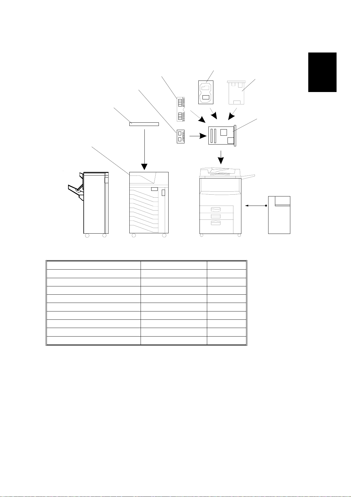
1.4 MACHINE CONFIGURATION
5
4
3
2
1
6
7
Overall
Information
Item Machine Code No.
Printer Controller A852 7
PostScript Kit A866 3
Hard Disk A853 5
Network Interface Board A855 6
Mailbox G909 1
Mailbox Bridge Unit G912 2
RAM SIMM --- 4
Printer Manual/Driver Kit A868 ---
A852V500.WMF
1-3
Page 5
STRUCTURE 28 January, 1999
1.5 STRUCTURE
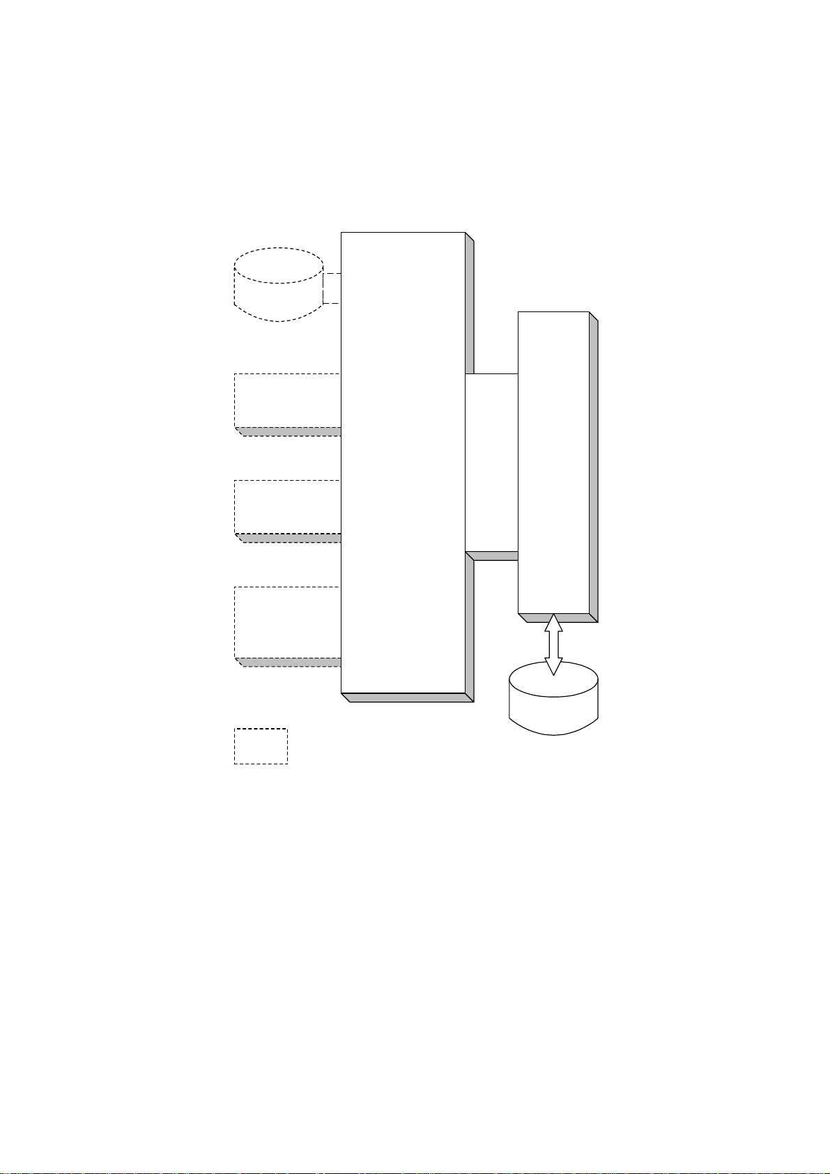
1.5.1 BLOCK DIAGRAM
Hard Disk
(Controller)
PS Kit
DRAM
SIMM
Network
Interface
Board
: Printer's Options
Printer
Controller
MB SBICU
Hard Disk
(Main Frame)
A852V501.WMF
1-4
Page 6

28 January, 1999 STRUCTURE
1.5.2 DESCRIPTIONS
1. Printer Controller
The printer controller handles the following functions:
•
Printer host interface
•
Printing functions
•
Interface and control of additional controller options (HDD, PS kit, DRAM SIMM,
and network interface board)
2. Hard Disk (option)
This HDD stores the additional soft fonts and macros (both PCL and PS fonts).
3. PS Kit (option)
This is to add the PostScript level 3 feature.
Overall
Information
4. Network Interface Board (option)
The network interface board is an additional printer interface to allow the printer to
be used on a network.
5. DRAM SIMM (option)
There are two DRAM SIMM slots. This is used for an additional printer processing
memory area. 8, 16, or 32 Mbyte standard SIMM modules can be installed. As a
result, up to 72 Mbytes of RAM are installable (8 Mbytes on board plus 64 Mbytes
of optional SIMM).
6. MB (Mother Board)
This connects the controller to the SBICU board in the printer controller box.
1-5
Page 7
28 January, 1999 HARDWARE OVERVIEW
2. DETAILED SECTION DESCRIPTIONS
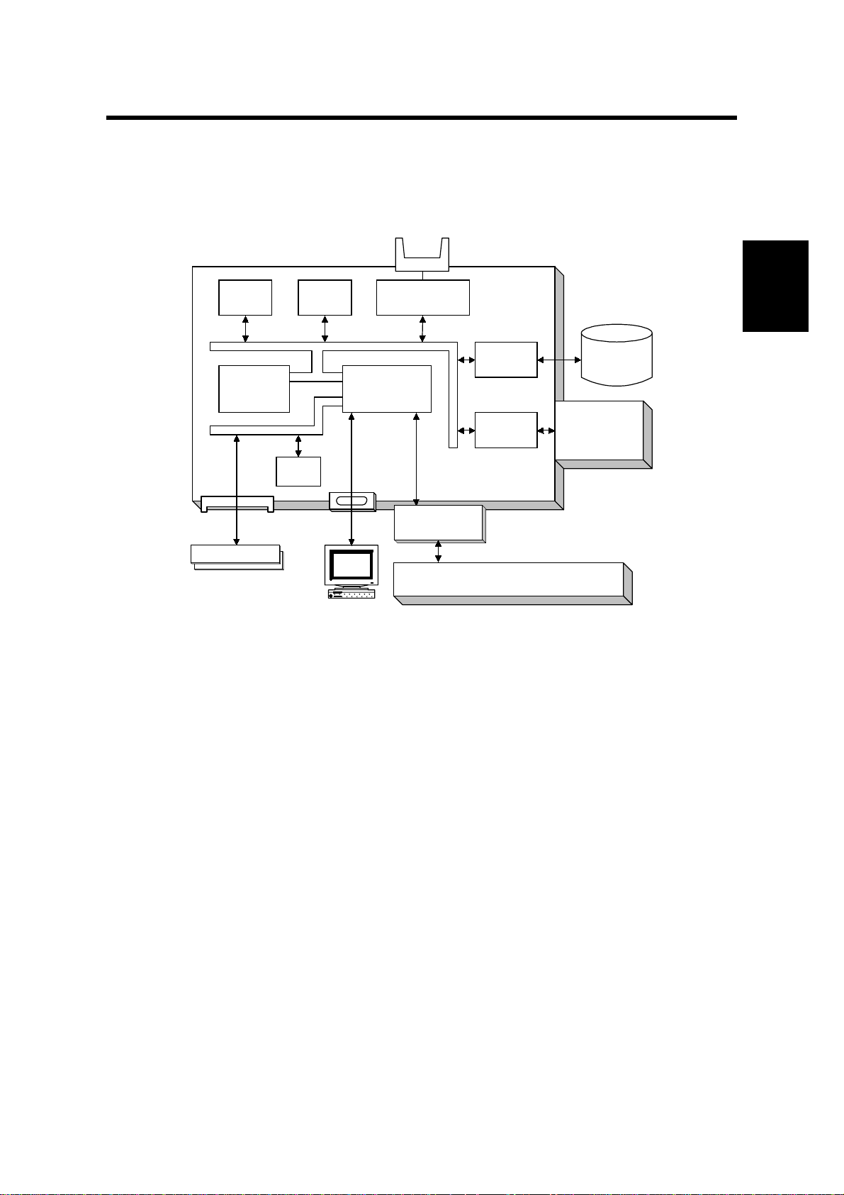
2.1 HARDWARE OVERVIEW
Flash
ROM
CPU
DRAM Bus
DRAM SIMM
DRAM SIMM
NVRAM
ROM & I/O Bus
CPU Bus
DRAM
PC/AT Compatible
via Parallel Port
Flash Memory
Card I/F
Co-
Processor
Mother Board
EIDE Disk
Interface
NIB
Interface
Printer Controller
SBICU
HDD
Network
Interface
Board
A852D500.WMF
The above block diagram shows the major components of the printer controller.
The main features of the controller are as follows.
Detailed
Descriptions
1. CPU
An IBM PPC603 processor is used. A 33 MHz oscillator is used as the clock
source for both this CPU and the coprocessor.
The processor with a bus clock of 33 MHz, and internal clock of 133 MHz.
2. Co-processor
This performs the following functions.
•
ROM control
•
I/O control
•
DRAM control
•
Printer video interface
•
Printer communication interface
•
IEEE 1284 compliant bi - dir ectional par all el port interface
•
Interrupt control
2-1
Page 8

HARDWARE OVERVIEW 28 January, 1999
3. ROM memory
1) Flash ROM (4 Mbytes)
This flash ROM includes boot code, operation system code, PCL5e codes,
PCL6 code, and font data for both PCL languages (resident fonts).
2) ROM SIMM (4 Mbytes for the PostScript option)
This ROM SIMM includes the PostScript code and PostScript font data.
4. NVRAM (8 Kbytes)
This NVRAM contains the printer settings, job record data, and error record
data.
5. Network Interface Board Interface
This controls the optional network interface board, and printer MIB is provided to
support the network operations.
6. Hard Disk Drive Interface (Enhanced IDE)
This HDD interface is provided to support storage of fonts and macros
downloaded from a PC.
7. Flash Memory Card Interface
The flash memory card for updating the controller and PostScript firmware is
connected to this flash memory card slot.
8. Power-on Self Diagnostic
When the controller is turned on, the controller performs a self diagnostic test.
2-2
Page 9
28 January, 1999 IMAGE PRINTING
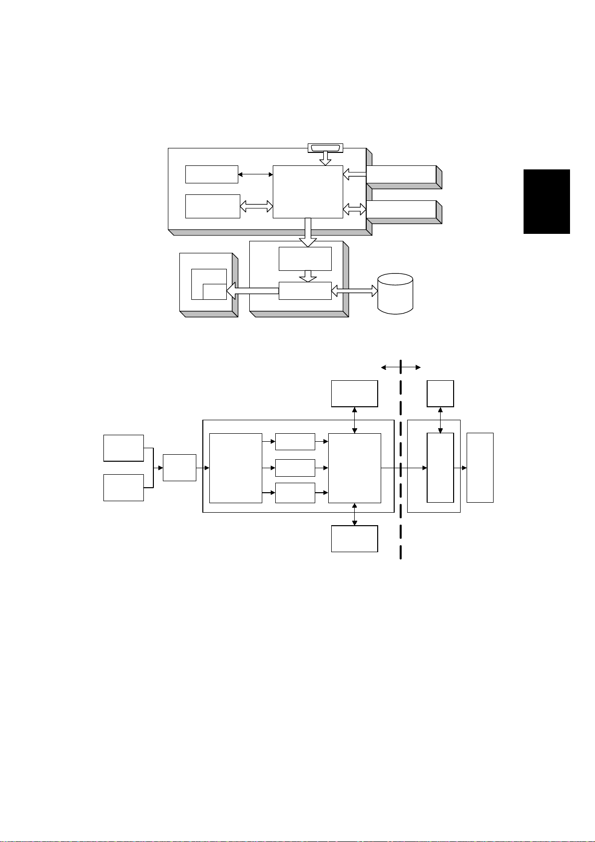
2.2 IMAGE PRINTING
Parallel Interface, from PC
Printer Controller
NIB
Parallel
Buffer
CPU
Resident
RAM
LD Unit
GAVD
FCI
Co-processor
Intelligent
Personality
Selection
SBICU
Co-processor
IPU
GA1
PCL-5e
PCL-6
Post
script
DRAM SIMM
Resident
RAM
Image Data
Generation
NIB
Detailed
Descriptions
HDD
A852D502.WMF
Base EnginePrinter Controller
HDD
SBICU
IPU LD
DRAM
SIMM
A852D503.WMF
The printer controller receives the print data from the computer through the parallel
or network interface port. The co-processor handles the image data but it only
makes a raster image. All image processing, such as edge smoothing and toner
saving, are done in the base engine.
The image data from a PC goes to the buffer in the resident RAM. Then, it goes to
the co-processor. The co-processor selects the printer language automatically,
then the co-processor generates the print data to match the selected printer
language. After generating the print data, the co-processor sends it to the LD unit
through the IPU on the SBICU board. At that time, the data is also sent to the hard
disk for multiple printing and sorting, as well as backup in case of paper jams.
2-3
Page 10
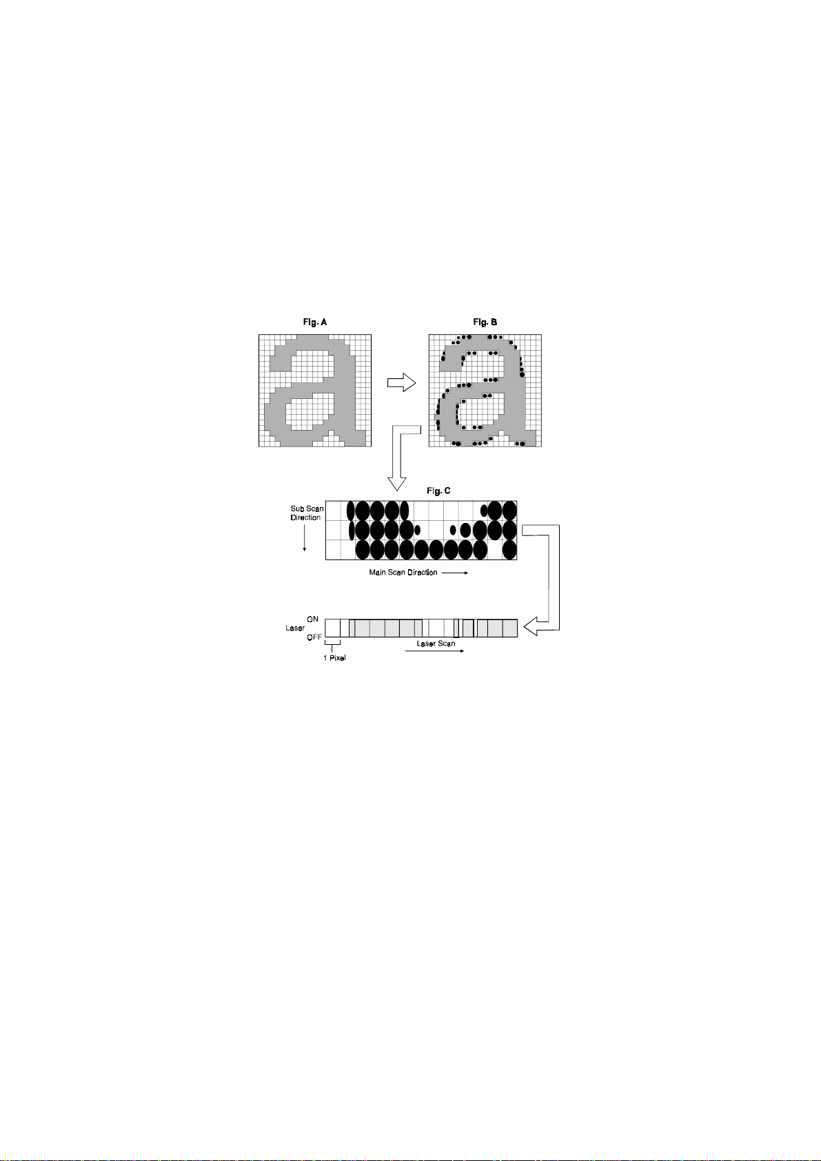
IMAGE DATA PROCESSING 28 January, 1999
2.3 IMAGE DATA PROCESSING
The FCI in the LD unit is responsible for edge smoothing and toner saving
functions.
The edge smoothing and toner saving modes can be switched on or off using the
printer user tool or the printer driver.
2.3.1 EDGE SMOOTHING
A850D504.WMF
Usually, binary picture processing generates jagged edge on characters as shown
in the above left illustration. The FCI reduces the edges of characters using edge
smoothing.
Whether or not the object pixel undergoes smoothing depends on the surrounding
image data. Smoothing for the object pixel is done by changing the laser pulse
position.
2.3.2 TONER SAVING MODE
Toner saving is done by reducing the number of black dots printed, not by varying
the development bias. In toner saving mode, the image data is filtered through a
matrix.
As a result of passing through the filter, less toner is used to create the latent
image on the drum, and black areas print as gray.
2-4
Page 11

28 January, 1999 FEATURES
2.4 FEATURES
2.4.1 SORTING
If “Collate” is turned on and a multicopy job is printed, the first copy of the job will
be printed directly. At the same time, the image data for the copy job is stored in
the hard disk of the main machine. When the main machine prints the next copy,
the next copy will be printed from the hard disk.
If the finisher is not installed, the rotate sort feature can be used. The image is
rotated by the SBICU, in the same way as image rotation for the copier.
2.4.2 DUPLEX PRINTING
Duplex printing is available with all output bin options but not all paper sizes (refer
to the specifications section of the copier manual). If a job specifies duplex but the
paper size to be used is not usable in the duplex unit, the job will be printed
simplex.
Duplex printing is available in two binding methods: Short-edge binding and Longedge binding.
In short-edge binding, when printing the second side of a page, the image may
require rotation. The image is rotated by the co-processor in the printer controller.
The co-processor corrects the image printing order for duplexing as follows.
•
Larger than A4 lengthwise/LT lengthwise (example 8 pages)
1st page – 3rd page – 2nd page – 5th page – 4th page – 7th page – 6th page –
8th page
Detailed
Descriptions
•
Up to A4 lengthwise/LT lengthwise (example 14 pages)
1st page – 3rd page – 5th page – 2nd page – 7th page – 4th page – 9th page –
6th page – 11th page – 8th page – 13th page – 10th page – 12th page – 14th
page
2-5
Page 12

FEATURES 28 January, 1999
2.4.3 STAPLING
Stapling is only available when the finisher is installed.
The finishers have the following stapling positions.
1) Upper left, diagonal
2) Upper right, diagonal
3) Left, two staples
4) Top, two staples
5) Right, two staples
6) Upper left, horizontal
7) Upper right, horizontal
8) Upper left, vertical
9) Upper right, vertical
Depending on the paper orientation, the image may have to be rotated. This image
rotation is done by the co-processor in the printer controller.
There is a limit for the number of sheets which can be stapled by finisher. If a job
that specifies stapling has more than this number of sheets, it will not be stapled.
2.4.4 PUNCHING
Punching is only available when the punch unit is installed with the finisher. The
number of holes depends on the type of punching unit. The punching unit has only
one available position, so the relationship between the punching position and the
printed image depends on the paper feeding orientation and imaging. The
punching positions are defined as follows.
1) Left
2) Top
3) Right
2-6
Page 13

28 January, 1999 FEATURES
2.4.5 JAM RECOVERY
If the jam recovery feature is on and a paper jam occurs, the controller will reprint
all pages for which a feed-out indication has not been received from the main
machine. In usual cases, all image data from the controller will be sent to the hard
disk on the main machine, When a jam occurs, the recovery data will be sent f rom
the hard disk on the main machine.
2.4.6 AUTO TRAY SELECT
When “Auto Select” is selected with the printer driver, the printer searches for a
tray that contains the specified size of normal plain paper. The search starts from
the LCT, and when a tray that contains the specified size of paper is found, the
printer starts printing and feeds paper from that tray. The search sequence is as
follows.
LCT – 1st tray – 2nd tray – 3rd tray – LCT
Detailed
Descriptions
The default setting for the current tray is LCT. If the LCT is not installed, the default
is the 1st tray.
2.4.7 POWER ON SELF DIAGNOSTICS
When the controller is turned on, it performs a self diagnostic sequence of tests
automatically. If any errors were de tected, an error message will be displayed on
the operation panel.
Test Items
Devices always tested
•
Co-processor
•
Flash ROM
•
Resident RAM
•
NVRAM
•
Engine I/F
Devices tested when they are installed
•
DRAM SIMM
•
PS DIMM I/F
•
HDD I/F
•
Network interface board I/F
2-7
Page 14

FEATURES 28 January, 1999
2.4.8 DOCUMENT SERVER
The Document Server enables to save documents in the mainframe memory
(HDD), then can be edited and printed as operator want.
There are two ways to save documents.
•
Sending data from the computer
•
Scanning originals from the document feeder (ADF), or the exposure glass of
the machine
There are three featurs.
•
Prepare the documents operator want to save.
•
Save the documents.
The documents are saved in the mainframe memory.
•
Print the documents.
Operator can print any of the saved documents with any desired settings at
any time.
2-8
Page 15
28 January, 1999 HARD DISK
2.5 HARD DISK
Two hard disks are used for the printer functions. One is connected to the printer
controller (Printer HDD). The o ther is in the main machine (Engine HDD).
2.5.1 PRINTER HDD
When the main power switch is turned on after the printer HDD is installed, the
machine asks you to format the hard disk in the printer mode.
If you press the “Continue” button, the machine formats the hard disk. At this time,
two partitions will be made on the hard disk. One is for PCL and the other is for
PostScript (fonts and macros only).
If you press the “Cancel” button, the machine determines that there is no optional
printer hard disk.
Detailed
Descriptions
2.5.2 ENGINE HDD
The hard disk in the main machine is used for copy, printer and document server
functions. Therefore, the hard disk has three partitions: for copier, printer, and
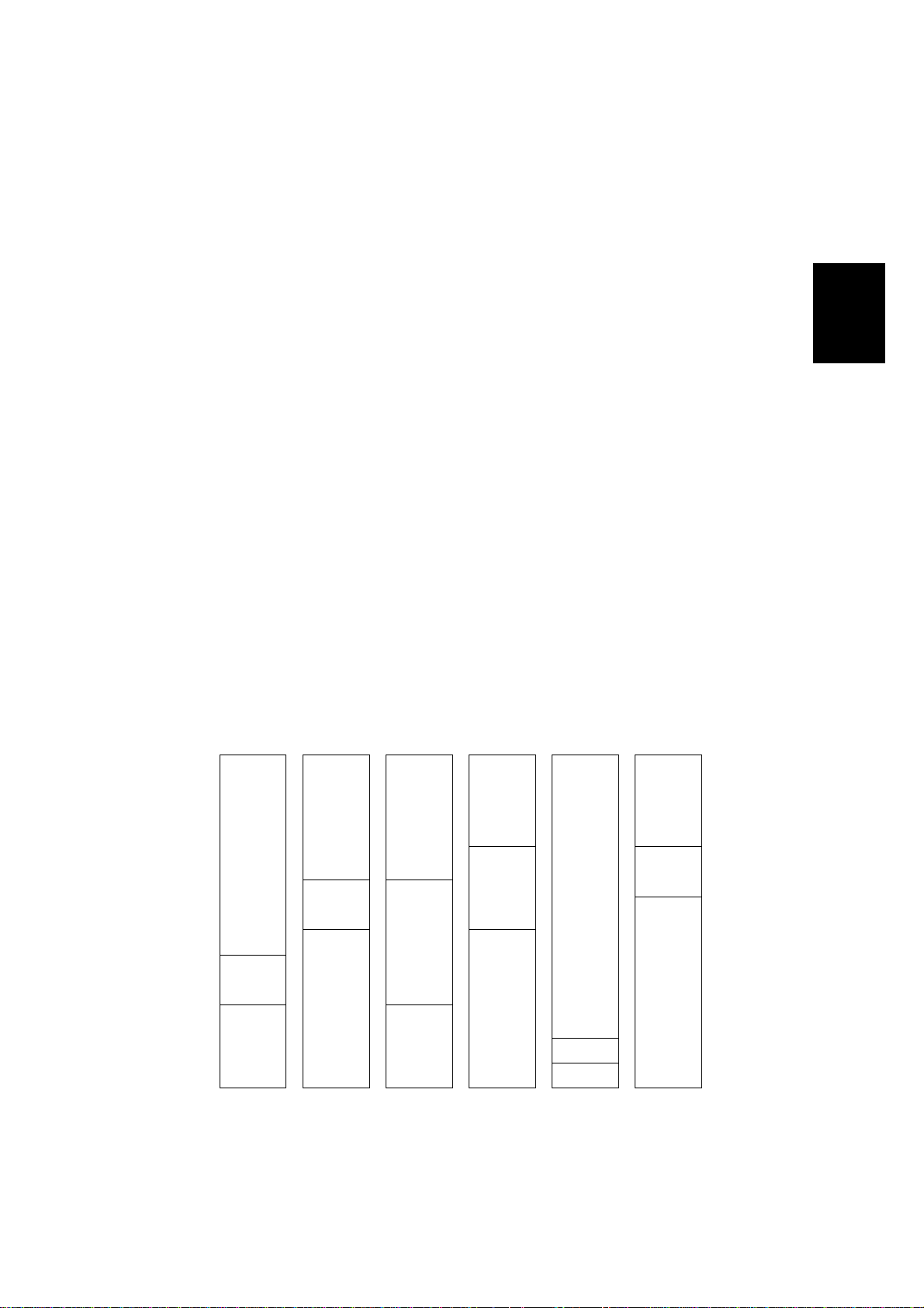
document server (one of the copier features). The sizes of the partitions depends
on the setting of “System Settings – Count Manager – Memory Allocation”, as
shown below.
OMB
1650 MB
Copy
Priority
(Default)
Copier
1050 MB
Printer
200 MB
Document
Server
400 MB
Document
Server
Priority
Copier
650 MB
Printer
200 MB
Document
Server
800 MB
Printer
Priority
Copier
650 MB
Printer
600 MB
Document
Server
400 MB
Min. Memory
for Copier
Copier
450 MB
Printer
400 MB
Document
Server
800 MB
Max. Memory
for Copier
Copier
1450 MB
Document Server
100 MB
Document Server
100 MB
Max. Mem.
for Doc.
Server
Copier
450 MB
Printer
200 MB
Document
Server
1000 MB
2-9
A850D505.WMF
Page 16

28 January, 1999 PRI NTER CONTROLLER
3. INSTALLATION PROCEDURE
3.1 PRINTER CONTROLLER
3.1.1 ACCESSORY CHECK
Check the accessories in the box against the following list.
No. Description Q’ty
1. Controller Box Cover 1 2 Cable Clamp 1 3 Key Top - Copy/Printer/Document Server 1 4 Tapping Screw – M4 x 8 3 5 Tapping Screw – M3 x 6 6 6 Ferrite Core 1 7 Installation Procedure 1
Installation
3-1
Page 17

PRINTER CONTROLLER 28 January, 1999
3.1.2 INSTALLATION PROCEDURE
[A]
[B]
[D]
[C]
A852I501.WMF
[F]
[E]
A852I502.WMF
ø
CAUTION
Unplug the copier power cord before starting the following procedure.
[G]
1. Disconnect the ADF connector [A].
2. Remove the upper rear cover [B] (2 screws [C]).
3. Remove the bracket [D] (2 screws).
4. Remove the cable folder [E] (1 screw).
5. Stretch the flat cable [F].
6. Thread the flat cable through the ferrite core [G].
NOTE:
The ferrite core drops easily, so bend the end of cable as shown in the
diagram on the next page.
3-2
Page 18

28 January, 1999 PRI NTER CONTROLLER
[B]
[C]
[B]
[G]
[F]
[A]
A852I504.WMF
[H]
[D]
[I]
[J]
Installation
[E]
A852I500.WMF
A852I505.WMF
7. Install the controller box [A] (3 screws).
8. Attach the flat cable [B] to the ferrite core [C].
9. Connect the flat cable [D] as shown (1 connector).
10. Connect the cable [E] and attach the clamp [F] (1 connector and 1 screw)
11. Install the cover [G] (5 screws).
12. Remove the key top cover [H] of the operation panel.
13. Install the key top [I] and the key top cover [J] on the operation panel as shown.
3-3
Page 19

PRINTER CONTROLLER 28 January, 1999
14. Make sure that the parallel cable is not connected to the controller and turn the
machine on, then check the setting of the following copier SP mode.
•
SP5-907: Plug & Play Brand Name and Production Name Setting – select the
correct one.
•
Sp5-811: Machine Serial Number-make sure that this is stored.
15. If the customer wishes to expand the hard disk space in the main machine for
use by the printer, change the setting of “Memory Allocation” (User Tools –
System Settings – Count. Manager – Memory Allocation) to “Printer Priority”.
16. Print the Printer Configuration Page (User Tools – Printer Features – Test –
Print Configuration page) to check the printer controller connection.
17. If the parallel cable is going to be connected, turn off the machine first and
connect the parallel cable, then turn the machine back on again.
NOTE:
If the Plug & Play Brand Name setting is changed, perform the power on
cycle twice to create a valid new Brand Name, prior to connecting the
printer cable to the PC.
3-4
Page 20

28 January, 1999 HARD DISK DRIVE
3.2 HARD DISK DRIVE
3.2.1 INSTALLATION PROCEDURE
[B]
[A]
Installation
A853I501.WMF
[C]
[E]
A853I503.WMF
ø
CAUTION
Unplug the copier power cord before starting the following procedure.
NOTE:
When this hard disk drive a nd the printer controller (A852) are installed at
the same time, skip step 1 to 6.
[D]
1. Disconnect the ADF connector [A].
2. Remove the upper rear cover [B] (2 screws [C]).
3. Remove the cover [D] (5 screws).
4. Disconnect the cable [E] (1 connector, 1 clamp).
3-5
Page 21

HARD DISK DRIVE 28 January, 1999
[F]
A853I504.WMF
[H]
A853I505.WMF
5. Remove the controller box [F] (3 screws, 1 connector, 1 ferrite core).
NOTE:
The ferrite core drops off easily.
[G]
6. Remove the controller cover [G] (12 screws).
7. Remove the controller board [H] (7 screws).
3-6
Page 22

28 January, 1999 HARD DISK DRIVE
[B]
[C]
[A]
Installation
A853I502.WMF
8. Attach the HDD brackets [A] to the hard disk drive [B] as shown (2 screws
each).
9. Connect the cable [C] to the hard disk drive.
10. Attach the hard disk drive to the printer controller (4 screws, 1 connector).
11. Install the printer controller board in the controller box.
12. Install the controller box in the main mach ine (refer to the Printer Controller
Installation Procedure).
13. After turning on the main switch and pressing the printer key, the machine asks
you to format the hard disk drive.
3-7
Page 23

POSTSCRIPT KIT 28 January, 1999
3.3 POSTSCRIPT KIT
3.3.1 INSTALLATION PROCEDURE
[B]
[A]
[E]
A853I501.WMF
[C]
A866I500.WMF
[F]
A866I501.WMF
ø
CAUTION
Unplug the copier power cord before starting the following procedure.
[D]
NOTE:
When this hard disk and the printer controller (A852) are installed at the
same time, skip steps 1 to 3.
14. Disconnect the ADF connector [A].
15. Remove the upper rear cover [B] (2 screws [C]).
16. Remove the cover [D] (5 screws).
17. Install the PostScript board [E] as shown.
18. Attach the PostScript decal [F] to the front cover as shown.
3-8
Page 24

28 January, 1999 NETWORK INTERFACE BOARD
3.4 NETWORK INTERFACE BOARD
3.4.1 INSTALLATION PROCEDURE
[B]
[A]
Installation
[C]
A853I501.WMF
ø
CAUTION
[E]
A853I503.WMF
Unplug the copier power cord before starting the following procedure.
NOTE:
When this network interface board and the printer controller (A852) are
installed at the same time, skip step 1 to 6.
1. Disconnect the ADF connector [A].
2. Remove the upper rear cover [B] (2 screws [C]).
[D]
3. Remove the cover [D] (5 screws).
4. Disconnect the cable [E] (1 connector, 1 clamp).
3-9
Page 25

NETWORK INTERFACE BOARD 28 January, 1999
[F]
A853I504.WMF
[H]
A249I553.WMF
5. Remove the controller box [F] (3 screws, 1 connector, 1 ferrite core).
NOTE:
The ferrite core drops off easily.
6. Remove the controller cover [G] (12 screws).
7. Remove the controller board [H] (7 screws).
3-10
[G]
Page 26

28 January, 1999 NETWORK INTERFACE BOARD
[E]
[A]
[G]
[C]
[B]
[F]
A855I502.WMF
[D]
[I]
[H]
A855I513.WMF
8. Attach two spacers [A] to the printer controller board [B] (1 screw each).
9. Remove the cover bracket [C] (2 screws).
10. Install the network interface board [D] as shown (2 screws [E] in the accessory
box, 2 screws [F] were used for the cover bracket [C]).
11. Connect the cable [G] to both the network interface board and printer controller
as shown.
Installation
12. Install the printer controller board in the controller box.
13. Install the controller box in the main mach ine (refer to the Printer Controller
Installation Procedure).
14. Attached the ferrite core [H] to the STP cable [I] as shown.
3-11
Page 27

DRAM SIMM 28 January, 1999
3.5 DRAM SIMM
3.5.1 REQUIRED SPECIFICATION CHECK
Before installing the DRAM SIMM, check tha t it satisfies the requirements below.
Type PC Compatible
Number of bins 72 pins
Access speed 70 ns or faster
Capacity 8, 16, or 32 MB
Parity Any OK
3.5.2 INSTALLATION PROCEDURE
– For A229 copier –
[B]
[A]
A853I501.WMF
[C]
ø
CAUTION
Unplug the copier power cord before starting the following procedure.
1. Disconnect the ADF connector [A].
2. Remove the upper rear cover [B] (2 screws [C]).
3-12
Page 28

28 January, 1999 DRAM SIMM
[F]
[D]
Installation
[E]
A853I503.WMF
[G]
A852V505.WMF
3. Remove the cover [D] (5 screws).
4. Disconnect the cable [E] (1 connector, 1 clamp).
5. Disconnect the flat cable [F] (1 connector, 1 ferrite core).
NOTE:
The ferrite core drops off easily.
6. Remove the controller cover [G] (12 screws).
3-13
Page 29

DRAM SIMM 28 January, 1999
[E]
A850I503.WMF
7. Install the DRAM [H], as shown.
NOTE:
Make sure that DRAM SIMM is installed properly.
3-14
Page 30

28 January, 1999 CONNECTING THE INTERFACE CABLES
3.6 CONNECTING THE INTERFACE CABLES
3.6.1 PARALLEL INTERFACE
An IEEE1284 compatible printer cable is required to connect the printer controller
to a host PC parallel port.
3.6.2 NETWORK INTERFACE
A STP (Shielded Twisted Pair) cable with RJ45 connectors is required to connect
the Network Interface Board to the computer network. (The cable should be
Category/Type 5 or better.) After hardware setup, the network setup should be
done by the user. The setup procedure is described in the NIB manual.
3.7 CHECKING THE CONNECTION
Installation
3.7.1 CONNECTION BETWEEN PRINTER CONTROLLER (and
related options; PostScript ROM, DRAM SIMM, Hard Disk
Drive, NIB) AND ENGINE.
1. Plug in the power cord and turn on the main and operation switches.
2. Enter the printer user mode.
1) Press the User Tool key.
2) Press the Printer Features button.
3. Print out the printer configuration page.
1) Select the List Print tab.
2) Press the Configuration Page button to print the configuration page. The
machine prints the printer configuration page automatically.
NOTE:
The printer configuration page is similar to that shown on the next page.
For more detailed information about the operation panel settings, refer to
the operation manual.
3-15
Page 31

CHECKING THE CONNECTION 28 January, 1999
CONFIGURATION MENU
RESOLUTION = 600
Printer Configuration Page
AUTO CONTINUE = ON
SMOOTHING = ON
PCL MENU
ORIENTATION = PORTRAIT
FORM LENGTH = 60 LINES
FONT SOURCE = INTERNAL
FONT NUMBER = 0
POINT SIZE = 12.00
PITCH = 10.00
SYMBOL SET = ROMAN-8
POSTSCRIPT MENU
PRINT ERRORS = OFF
FEEDER MENU
PAGE SIZE = LETTER
PAPER TRAY = AUTO
AUTO TRAY CHANGE = ON
BYPASS PAPER TYPE =
DUPLEX = OFF
BINDING = LONG
SEPARATION = OFF
STAPLE = OFF
PUNCH = OFF
PARALLEL MENU
EMULATION = AUTO
BIDIRECTION = ON
I/O TIMOUT = 30
CONFIGURATION MENU
RESOLUTION = 600
AUTO CONTINUE = ON
SMOOTHING = ON
AUTOCONT TIMEOUT = 30
NETWORK MENU
I/O TIMEOUT = 30
TCP/IP SETTING
IP ADDRESS = 131.100.100.111
SUBNET MASK = 255.255.255.0
GATEWAY ADDRESS = 131.100.100.1
PRINTER DETAILS
MODEL:
MANUFACTURER:
MACHINE S/N: 00000010200
SERVICE PHONE: 00-0000-0000
FIRMWARE LEVELS:
Controller 1.15
PeerlessPrint5-E V 1.4.10 98/05/06
PeerlessPrintXL V 1.1.10 98/05/06
PS 1.05
PRINTER OPTIONS
Printer Hard Disk Drive
Adobe Postscript
Network Interface Board
PAPER HANDLING OPTIONS
MSU Installed
Tandem Tray 1
Standard Tray 2
Internal LCT Tray 3
Manual Paper Tray
Large Capacity Tray
Duplex Unit
9 Bin Mailbox Unit
Finisher 3000
Punch Unit, 2 Hole
TOTAL MEMORY = 72 MB
AUTOCONT TIMEOUT = 30
NETWORK MENU
[C]
I/O TIMEOUT = 30
TCP/IP SETTING:
IP ADDRESS = 131.100.100.111
SUBNETMASK = 255.255.255.0
GATEWAY ADDRESS = 131.100.100.1
PRINTER DETAILS
MODEL:
MANUFACTURER:
MACHINE S/N: 00000010200
SERVICE PHONE: 00-0000-0000
[D]
FIRMWARE LEVELS:
Controller 1.15
PeerlessPrint5-E V 1.4.10 98/05/06
PeerlessPrintXL V 1.1.10 98/05/06
PS 1.05
PRINTER OPTIONS:
[A]
Printer Hard Disk Drive
Adobe Postscript
Network Interface Board
PAPER HANDLING OPTIONS:
MSU Installed
Tandem Tray 1
Standard Tray 2
Internal LCT Tray 3
Manual Paper Tray
Peerless Print is a trademark of Peerless System Corporation.
Adobe, PostScript, the Adobe logo and the Postscript logo are the trademarks
of Adobe System Incorporated.
A852I504.WMF
Large Capacity Tray
Duplex Unit
9 Bin Mailbox Unit
Finisher 3000
Punch Unit, 2 Hole
[B]
TOTAL MEMORY = 72 MB
A852I505.WMF
Check the following:
•
For the printer controller board, confirm that the machine prints the printer
configuration page.
•
For the hard disk drive and PS kit, confirm that the configuration page includes
them in the “Printer Options” section [A].
•
For DRAM SIMM, confirm that “Total Memory” [B] printed on the configuration
page shows the correct amount of memory in the machine (including the 8 MB
on board and the SIMM).
•
For the NIB, confirm that the configuration page includes the “Network Menu”
section [C] and includes the network interface board in the “Printer Options”
section [A].
•
For the firmware version, check “Firmware Levels” [D].
If any problem occurs with the above checks, reinstall the printer controller and
other options. Then set up the machine again and redo the test.
3-16
Page 32

28 January, 1999 CHECKING THE CONNECTION
3.7.2 CONNECTION BETWEEN MAIN CONTROLLER BOARD AND
THE NETWORK INTERFACE BOARD
There are two ways to check the connection between the main controller board
and the network interface board.
1. To check “Network Menu” on the configuration page.
2. To check the Network Interface Board Status Sheet with the network
information that is printed automatically after power on.
Print the Network Interface Board Status Sheet
Whenever the main switch is turn ed on, the machine prints the network interface
board status sheet automatically.
NOTE:
If any problem occurs with the above check, reinstall the printer controller and other
options. Then set up the machine again and redo the test.
If the machine does not print the status sheet, check the Network menu in
the printer user tools.
Installation
3-17
Page 33

28 January, 1999 GENERAL CAUTION
4. SERVICE TABLE
4.1 GENERAL CAUTION
Do not turn off the machine or switch the controller off-line when the data LED is
blinking or is lit, or the data which has been sent to the contro ller will be lost. If you
need to do this, ask the customer for consent.
4.2 SERVICE PROGRAM MODE
4.2.1 SERVICE PROGRAM ACCESS PROCEDURE
The service program access procedure, such as “Entering Service Program (SP)
Mode” and “Exiting SP Mode” is the same procedure as for copier, as follows.
Entering SP mode
#
→
.
→
-
→
4
→
$
(hold it for more than 3 seconds.)
Exiting SP mode
Press the “Back” and “Exit” keys until the standby mode display appears.
4.2.2 SERVICE PROGRAM MODE TABLES
No. Description Function
01 Flash System From Parallel Downloads the printer controller firmware
from a P C throug h the parallel po r t.
02 Flash System From PCMCIA Downloads the printer controller firmware
using an IC card through the PCMCIA port.
03 Flash Postscript From Parallel
04 Flash Postscript From PCMCIA Downloads the PostScript firmware using an
05 Copy Flash ROM Copies the printer controller firmware
06 Format Disk Formats the hard disk drive
07 Print Job Log Data Prints the print/job count log page
08 Print Error Log Data Prints the printer error log page
09 Clear Job Log Counter Clears the print/job counter
10 Clear Error Log Data Clears the error log counter
11 Parallel Loop Back Test Performs the parallel loop back test
Downloads the PostScript firmware from a
PC through the parallel port.
IC card through the PCMCIA port.
between ROM DIMM and printer controller
Tables
Service
4-1
Page 34

DOWNLOADING NEW FIRMWARE 28 January, 1999
4.3 DOWNLOADING NEW FIRMWARE
New firmware for the printer controller and PostScript can be downloaded from a
PC through the parallel cable and from a flash memory card through the PCMCIA
port.
4.3.1 FIRMWARE UPDATE USING A FLASH MEMORY CARD
(SP02 AND 04)
1. Prepare a flash memory card that has been programmed with the latest
firmware.
NOTE:
•
Start Address – 000000h
•
Length – 3FFFFFh
2. Turn off the machine, remove the cover [A], and insert the flash memory card
[B] into the slot so that the “A” side of the card faces the front of the machine.
When you program a flash memory card with a firmware file, use the
following parameter settings.
[A]
[B]
A852M501.WMF
3. Turn on the machine and enter the printer SP mode.
4. Select the Flash tab.
5. Press “Flash System From PCMCIA” button or “Flash PostScript From
PCMCIA” button depending on the firmware type.
6. Press “Yes” in reply to the confirmation message. Firmware download will take
several minutes.
7. After new firmware has been downloaded successfully, turn off the machine,
remove the card from the slot, and turn the machine back on.
8. Print the “Printer Configuration Page” to check the new firmware version ([User
Tools] – [Printer Features] – [List Print tab] – [Configuration Page]).
The firmware version number is printed in the “Printer Details” section of the
configuration page.
4-2
Page 35

28 January, 1999 DOWNLOADING NEW FIRMWARE
4.3.2 FIRMWARE UPDATE FROM PARALLEL PORT
1. Prepare the latest firmware file and Fcopy.exe on a host computer.
2. Turn off the machine, connect the host computer using a parallel cable, and
turn the machine back on.
3. Enter the printer SP mode.
4. Select the Flash tab.
5. Press “Flash System from Parallel” button or “Flash Postscript From Para llel”
button depending on the firmware type.
6. Press “Yes” in reply to the confirmation message.
7. On the host computer, start MS-DOS Prompt and type the following command.
Either
C:\> FCOPY path\filename
or
C:\> COPY /b path\filename port
CAUTION:
Do not turn off the machine while “Downloading New System Software”
is displayed on the LCD, even if FCOPY has finished in the MS-DOS
Prompt.
8. After new firmware has been downloaded successfully, turn off the machine,
disconnect the printer cable if necessary, and turn the machine back on.
9. Print the “Printer Configuration Page” to check the new firmware version ([User
Tools] – [Printer] – [List Print] – [Configuration Page]).
The firmware version number is printed in the “Printer Details” section of the
configuration page.
4.3.3 FORMATING THE HARD DISK
This function is used to format the printer hard disk. If the hard disk is formatted,
the stored data (downloaded fonts and macros) will be erased. So, when
performing this function, ask the customer for consent. After this operation, advise
the customer to restore their data, if necessary.
1. Enter the printer SP mode.
2. Select the Flash tab.
Tables
Service
3. Press “Format Disk” button.
4. Press “Yes” in reply to the confirmation message. Hard disk formatting will take
several minutes.
5. After confirming that formatting was successful, turn the machine off and back
on again.
4-3
Page 36

DOWNLOADING NEW FIRMWARE 28 January, 1999
4.3.4 COPY FLASH ROM
There are two functions; one is to copy the printer controller firmware from the
ROM DIMM to the printer controller, the other is the opposite way.
Download from ROM DIMM to printer controller
When downloading the printer controller firmware from either the flash memory
card or a PC was not successful and the printer controller does not start up, the
controller firmware cannot be downloaded from the flash memory card or a PC to
recover the machine. However, the firmware can be downloaded from ROM DIMM
using this function, using the following procedure.
[A]
CS0
TB1
CS1
CN1
Printer Controller
CS0
TB1
CS1
CS1
TB1
CS0
TB1
IC41
CS1
TB1
CS0
IC10IC9
ROM DIMM
A850M500.WMF
TB1
[B]
TB2
1. Remove the printer controller.
2. Change the position of the TB1 jumper [A] on the controller from CS0 to CS1.
3. Change the position of the TB1 jumper [B] on the ROM DIMM that contains the
controller firmware from CS 1 to CS0.
4. Install the ROM DIMM on the controller.
CAUTION:
Make sure to install the correct ROM DIMM in the PostScript SIMM.
5. Install the printer controller and turn on the machine.
6. Enter the printer SP mode and press “Copy Flash ROM” button.
7. Press “Yes” in reply to the confirmation message.
8. After downloading is successful, turn off the machine and remove the printer
controller then remove the ROM DIMM a s well.
9. Reposition the jumpers on the printer controller and ROM DIMM.
10. Reinstall the printer controller then turn on the machine.
11. Check that the printer controller starts up.
4-4
Page 37

28 January, 1999 DOWNLOADING NEW FIRMWARE
Download from the controller to ROM DIMM
CAUTION:
1. Remove the printer controller.
2. Install the ROM DIMM on the controller.
3. Install the printer controller and turn on the machine.
4. Enter the printer SP mode and press “Copy Flash ROM” button.
5. Press “Yes” in reply to the confirmation message.
6. After downloading is successful, turn off the machine and remove the printer
controller then remove the ROM DIMM a s well.
7. Reinstall the printer controller then turn on the machine.
Never perform this function if the PostScript ROM SIMM is installed on
the controller. Otherwise, the controller firmware will be copied to the
PostScript kit. Take out the PostScript ROM SIMM and install a blank
one.
4.3.5 PARALLEL LOOP BACK TEST (SP11)
1. Plug the loop back connector into the
parallel port of the printe r.
2. Enter the printer SP mode then press
“Parallel Loop Back Test” button.
3. Press “Yes” in reply to the
confirmation message. The result of
the test will be displayed on the
operation panel.
Pin No.
1
2
3
4
5
6
7
8
9
10
11
12
13
14
15
16
17
18
19
20
21
22
23
24
25
26
27
28
29
30
31
32
33
34
35
36
Signal Name
/STROBE
DATA_1
DATA_2
DATA_3
DATA_4
DATA_5
DATA_6
DATA_7
DATA_8
/ACK
BUSY
PE
SELECT
/AUTOFD
NC
GND
GND
PLH
GND
GND
GND
GND
GND
GND
GND
GND
GND
GND
GND
GND
/INIT
/FAULT
NC
NC
NC
/SELECTION
Tables
Service
4-5
A850D501.WMF
Page 38

USER PROGRAM MODE 28 January, 1999
4.4 USER PROGRAM MODE
A user program (UP) mode is available for printer features as well as for copy and
fax. Press the User Tool button to access it.
4.4.1 UP MODE TABLE (PRINTER FEATURES)
NOTE:
The function of each UP mode is explained in the Printer Reference
section of the operating instructions.
1. PCL
2. Postscript 1. Print Errors
3. Paper Feed
4. Parallel
5. Network
6. Configuration
7. List Print
8. Reset Select
1. Orientation
2. Form Length
3. Font Source
4. Font Number
5. Font Size
6. Font Pitch
7. Symbol Set
1. Paper Size
2. Tray Priority
3. Auto Tray Switching
4. Bypass Paper Type
1. Duplex
2. Sort
3. Staple
4. Punch
1. Printer Language
2. Bi-direction
3. I/O Timeout
1. I/O Timeout
2. IP Address
3. Subnet Mask
4. Gateway Address
1. Resolution
2. Auto Continue
3. Edge Smoothing
4. Continue Timeout
1. PS Font List
2. PCL Font List
3. PS Demo Page
4. PCL Demo Page
5. Configuration Page
1. Job Reset
2. Menu Reset
3. System Reset
4-6
Page 39

28 January, 1999 DIP SWITCHES/JUMPER PINS/LEDS
4.5 DIP SWITCHES/JUMPER PINS/LEDS
4.5.1 DIP SWITCHES
SW2:
No. Function On OFF
1 Destination for firmware
downloading
2
3
4 Operation mode
NOTE:
Source for firmware
downloading
The functions of DIP switches no.1, 2, and 3 are enabled when changing
the setting of no.4 to the off position. However,
settings
(keep them all on). Always do the firmware downloading using SP
mode.
To flash ROM
(No.2, 3)
On, On: From Host PC
On, Off: From flash memory card
Off, On: From ROM SIMM
Off, Off: From flash ROM
Normal operation
To ROM SIMM
Programming firmware
do not change the default
4.5.2 JUMPER PINS
TB1:
Function CS0 CS1
Bank setting for resident flash
ROM
Bank setting for flash
ROM is “0”.
Bank setting for flash
ROM is “1”.
TB2
Function UN-PROT PROT
Not used Do not change this setting. Keep at “UN-PROT”.
4.5.3 LEDS
Symbol Function
PWR This LED turns on when +5 V is supplied to the printer controller.
LED2
LED3
LED4
LED5
Refer to section 6.2 (LEDs) for more detail .
Tables
Service
4-7
Page 40

28 January, 1999 PRINTER CONTROLLER BOARD
5. REPLACEMENT AND ADJUSTMENT
ø
CAUTION
Turn off the main power switch and unplug the machine before attempting
any of the procedures in this section.
5.1 PRINTER CONTROLLER BOARD
[B]
[A]
A853I501.WMF
[C]
[E]
1. Disconnect the ADF connector [A].
2. Remove the upper rear cover [B] (2 screws [C]).
3. Remove the cover [D] (5 screws).
4. Disconnect the cable [E] (1 connector, 1 clamp).
A853I503.WMF
[D]
Adjustment
Replacement
5-1
Page 41

PRINTER CONTROLLER BOARD 28 January, 1999
[F]
[H]
A853I504.WMF
[G]
A853I505.WMF
5. Remove the controller box [F] (3 screws, 1 connector, 1 ferrite core).
NOTE:
The ferrite core drops off easily.
6. Remove the controller cover [G] (12 screws).
7. Remove the controller board [H] (7 screws).
5-2
Page 42

28 January, 1999 PRINTER CONTROLLER BOARD
[I]
A850R506.WMF
8. Remove the optional hard disk, network interface board, PS kit, and DRAM
SIMMs if they are installed (see their replacement procedures).
9. Remove the NVRAM [I] from the old printer controller and install it on the new
printer controller.
10. Install the options on the new printer controller.
Adjustment
Replacement
5-3
Page 43

HARD DISK 28 January, 1999
5.2 HARD DISK
[B]
[C]
[A]
A850R504.WMF
1. Remove the printer controller (see Printer Controller).
2. Dismount the hard disk [A] with bracket and IDE cable from the printer
controller (4 screws).
3. Remove the brackets [B] (2 screws each).
4. Disconnect the IDE cable [C].
5.3 NETWORK INTERFACE BOARD
[A]
[B]
A850R503.WMF
1. Remove the printer controller (see Printer Controller).
2. Disconnect the cable [A] from the printer controller and network interface board.
3. Remove the network interface board [B] (4 screws).
5-4
Page 44

28 January, 1999 NETWORK INTERFACE BOARD
5.3.1 POSTSCRIPT ROM BOARD AND DRAM SIMM
[B]
[A]
1. Remove the printer controller (see Printer Controller).
2. Remove the PS ROM board [A].
A850R505.WMF
3. Remove the DRAM SIMMs [B].
Adjustment
Replacement
5-5
Page 45

28 January, 1999 ERROR MESSAGES
6. TROUBLESHOOTING
6.1 ERROR MESSAGES
If an error occurred, the error LED lights (red light with the printer key) and an error
message is displayed on the LCD.
Copy
Document Server
Printer
A852T501.WMF
Service call (SC) codes
SC No. Description / Definition Possible Cause
Functional problems (Self diagnostic error) Printer controller board
SC2000
SC2001
SC2002
A diagnostic error occurred at power on. The
controller has a hardware problem.
Functional problems (Debug trap error)
An error has occurred in the controller. The
controller has a software problem.
Functional problems (Exception error) Printer controller board
An error has occurred in the controller. The
controller has a software or hardware problem.
defective.
The controller software
has a problem.
defective.
Trouble-
shooting
6-1
Page 46

ERROR MESSAGES 28 January, 1999
Other messages
The following errors might need assistance from service.
Error Message Condition Possible Cause
Printer HDD Error.
Press Reset to cancel
current job.
Parallel Communication
Error.
Please set up
communication
parameters in parallel
menu. Press Reset to
cancel current job.
Print overrun.
Press Reset to cancel
current job, or press
Continue to print.
Memory overflow.
Press Reset to cancel
current job.
A hard disk error was
detected during downloading
the macro or fonts.
Parallel communication error
occurred during a print job
via the parallel port.
This error occurred when a
file was being printed in
banding mode. A complex
page may not have enough
time to image a band while
the engine is printing the
previous page.
This error occurred during
printing.
The language has sent a file
that is too complex to
interpret in the available
memory.
• Printer HDD defective
• Printer controller
defective
• An item in the parallel
menu was set
incorrectly
• Parallel cable defective
• Printer controller
defective
• Insufficient memory
• A complex page is
printed
• The DRAM SIMM board
is defective
• The controller is
defective
• Insufficient memory
• A complex page is
printed
• The DRAM SIMM is
board defective
• The controller is
defective
6-2
Page 47

28 January, 1999 LEDS
6.2 LEDS
6.2.1 LOCATION
Four LEDs (LED2 to LED5) are located near SW2 on the printer controller. They
indicate display the progress of the self test, and errors and status conditions.
TB2
PWR
LED2
LED3
LED4
LED5
SW2
A850T500.WMF
6.2.2 LED CODE TABLE
Self diagnostic
The following LED table is for the self diagnostic function. When an error occurs
during the self diagnostic test, all four LEDs blink then indicate the error as shown
in the following table.
e.g.) RAM error:
All LEDs on (1 s) → off (1 s) → on (1 s) → off (1 s) → LED4 on (5 s) → from the
beginning.
1 = LED is lit, 0 = LED is off
LEDs
LED2 LED3 LED4 LED5
0 0 0 1 ROM error
0 0 1 0 RAM (resident, SIMM) error:
0 0 1 1 NVRAM error:
0 1 0 1 Fatal error
0 1 1 0 Debug trap error:
Description
note 1)
note 1)
note 2)
Trouble-
shooting
NOTE:
1) SC2000 is also displayed.
2) SC2002 is also displayed.
6-3
Page 48

LEDS 28 January, 1999
Controller Firmware Copy/Download
During controller firmware copying and downloading, the following LED status will
be indicated.
1 = LED is lit, 0 = LED is off, 1/0 = LED is blinking
LEDs
LED2 LED3 LED4 LED5
1 0 0 0 Data downloading
01/00 0Erasing
1/0 1/0 1 0 Progr amm ing
0001Verifying
1 0 0 1 Insufficient RAM error
1 0 1 0 Veri fy failure
1 0 1 1 Download failure (check sum error)
1 1 0 0 Erase failure
1 1 0 1 Download failure (other error)
1 1 1 1 Copy/download success
Description
6-4
 Loading...