

Ricoh SP4100N Diagram

G176/G177/G176L
SERVICE MANUAL
003037MIU


SERVICE MANUAL
G176/G177/G176L


G176/G177/G176L
SERVICE MANUAL
003037MIU


It is the reader's responsibility when discussing the information contained
within this document to maintain a level of confidentiality that is in the best
interest of Ricoh Corporation and its member companies.
NO PART OF THIS DOCUMENT MAY BE REPRODUCED IN ANY
FASHION AND DISTRIBUTED WITHOUT THE PRIOR
PERMISSION OF RICOH CORPORATION.
All product names, domain names or product illustrations, including
desktop images, used in this document are trademarks, registered
trademarks or the property of their respective companies.
They are used throughout this book in an informational or editorial fashion
only and for the benefit of such companies. No such use, or the use of
any trade name, or web site is intended to convey endorsement or other
affiliation with Ricoh products.
© 2007 RICOH Corporation. All rights reserved.


WARNING
The Service Manual contains information
regarding service techniques, procedures,
processes and spare parts of office equipment
distributed by Ricoh Corporation. Users of this
manual should be either service trained or
certified by successfully completing a Ricoh
Technical Training Program.
Untrained and uncertified users utilizing
information contained in this service manual to
repair or modify Ricoh equipment risk personal
injury, damage to property or loss of warranty
protection.
Ricoh Corporation

LEGEND
PRODUCT CODE COMPANY
G176 P7031n LP131n SP 4100N MLP31n
G177 P7035n LP136n SP 4110N MLP36n
G176L P7031nL LP131nL Aficio SP 4100NL MLP31nL
GESTETNER LANIER RICOH SAVIN
DOCUMENTATION HISTORY
REV. NO. DATE COMMENTS
*
1 5/2008 G176L Addition
03/2007 Original Printing


G176/G177/G176L
TABLE OF CONTENTS
INSTALLATION
1. INSTALLATION .......................................................................1-1
1.1 INSTALLATION REQUIREMENTS.......................................................1-1
1.1.1 ENVIRONMENT ..........................................................................1-1
1.1.2 MACHINE LEVEL ........................................................................1-2
1.1.3 REQUIRED SPACE.....................................................................1-2
1.1.4 POWER SUPPLY ........................................................................1-2
1.2 MACHINE INSTALLATION ...................................................................1-3
1.3 DATA OVERWRITE SECURITY UNIT INSTALLATION .......................1-4
1.3.1 INSTALLATION ...........................................................................1-4
1.3.2 CHECKING AND COMPLETING THE INSTALLATION ..............1-5
PREVENTIVE MAINTENANCE
2. PREVENTIVE MAINTENANCE ...............................................2-1
2.1 USER MAINTENANCE .........................................................................2-1
2.2 SERVICE MAINTENANCE ...................................................................2-2
REPLACEMENT AND ADJUSTMENT
3. REPLACEMENT AND ADJUSTMENT ....................................3-1
3.1 GENERAL.............................................................................................3-1
3.1.1 PRECAUTIONS ON DISASSEMBLY ..........................................3-1
3.1.2 RELEASING PLASTIC LATCHES...............................................3-2
3.1.3 AFTER SERVICING THE MACHINE...........................................3-3
3.2 SPECIAL TOOLS..................................................................................3-4
3.3 COVERS...............................................................................................3-5
3.3.1 FRONT COVER...........................................................................3-5
3.3.2 UPPER COVER...........................................................................3-5
SM i G176/G177/G176L

3.3.3 BY-PASS TRAY UNIT .................................................................3-6
3.3.4 EXTERIOR COVERS ..................................................................3-6
3.4 LASER UNIT .........................................................................................3-7
3.4.1 CAUTION DECAL LOCATIONS ..................................................3-7
3.4.2 POLYGON MIRROR MOTOR .....................................................3-7
3.4.3 LASER SYNCHRONIZATION DETECTOR.................................3-8
3.4.4 LASER UNIT................................................................................3-9
3.4.5 LASER DIODE UNIT .................................................................3-10
3.4.6 LASER BEAM PITCH ADJUSTMENT .......................................3-10
3.5 TRANSFER ROLLER .........................................................................3-13
3.6 TONER END SENSOR.......................................................................3-14
3.7 FUSING ..............................................................................................3-15
3.7.1 FUSING UNIT ............................................................................3-15
3.7.2 HOT ROLLER AND FUSING LAMP ..........................................3-16
3.7.3 PRESSURE ROLLER................................................................3-18
3.7.4 THERMISTOR AND THERMOSTAT .........................................3-18
3.7.5 HOT ROLLER STRIPPERS.......................................................3-19
3.8 PAPER FEED .....................................................................................3-20
3.8.1 PAPER FEED ROLLER.............................................................3-20
3.8.2 FRICTION PAD..........................................................................3-21
3.9 BY-PASS TRAY ..................................................................................3-22
3.10 PRINTER CONTROLLER BOARD ...................................................3-23
3.11 ENGINE BOARD...............................................................................3-24
3.12 MAIN MOTOR...................................................................................3-25
3.13 CLUTCHES.......................................................................................3-26
3.14 PSU, HVPS.......................................................................................3-27
3.15 COOLING FAN .................................................................................3-28
TROUBLESHOOTING
4. TROUBLESHOOTING .............................................................4-1
4.1 SERVICE CALL CONDITIONS .............................................................4-1
4.1.1 SUMMARY...................................................................................4-1
4.1.2 SC CODE DESCRIPTIONS.........................................................4-2
4.2 ERROR MESSAGES ..........................................................................4-18
4.3 GENERAL TROUBLESHOOTING ......................................................4-25
G176/G177/G176L ii SM

4.3.1 IMAGE ADJUSTMENT ..............................................................4-25
Registration Adjustment ................................................................4-25
Parallelogram Image Adjustment ..................................................4-25
4.3.2 ELECTRICAL DEFECTS ...........................................................4-26
Fuses ............................................................................................4-28
4.3.3 SKEW ADJUSTMENT ...............................................................4-29
4.3.4 STREAKS IN THE SUB SCAN DIRECTION..............................4-29
4.3.5 MISCELLANEOUS PROBLEMS................................................4-30
SERVICE TABLES
5. SERVICE TABLES...................................................................5-1
5.1 SERVICE PROGRAM MODE ...............................................................5-1
5.1.1 SERVICE PROGRAM MODE: OVERVIEW.................................5-1
Entering the Service Mode ..............................................................5-1
Setting a Service Program...............................................................5-2
Exiting Service Mode.......................................................................5-2
5.2 PRINTER CONTROLLER SERVICE MODE ........................................5-3
5.2.1 SERVICE MODE MENU ("1. SERVICE MENU") .........................5-3
5.2.2 BIT SWITCH PROGRAMMING ...................................................5-3
5.3 PRINTER ENGINE SERVICE MODE ...................................................5-4
5.3.1 SERVICE MODE TABLE .............................................................5-4
SP1-xxx: Feed.................................................................................5-4
SP2-xxx: Drum ..............................................................................5-10
SP3-xxx: Process ..........................................................................5-12
SP5-xxx: Mode ..............................................................................5-14
SP7-xxx: Data Log ........................................................................5-56
SP8XXX: Data Log 2.....................................................................5-71
5.4 FIRMWARE UPDATE .........................................................................5-82
5.4.1 TYPE OF FIRMWARE ...............................................................5-82
5.4.2 PRECAUTIONS .........................................................................5-82
Handling SD Cards........................................................................5-82
Upload/Download ..........................................................................5-83
Network Connection ......................................................................5-83
5.4.3 MACHINE FIRMWARE UPDATE ..............................................5-83
5.5 NVRAM DATA UPLOAD/DOWNLOAD...............................................5-85
SM iii G176/G177/G176L

5.5.1 UPLOADING NVRAM DATA .....................................................5-85
5.5.2 DOWNLOADING NVRAM DATA...............................................5-86
5.6 SD CARD APPLICATION MOVE........................................................5-88
5.6.1 OVERVIEW................................................................................5-88
5.6.2 MOVE EXEC..............................................................................5-88
5.6.3 UNDO EXEC..............................................................................5-89
5.7 CONTROLLER SELF TEST AT POWER-ON.....................................5-91
5.8 MENU MODE......................................................................................5-92
5.9 CONTROLLER BOARD DIP SWITCHES ...........................................5-98
DETAILED DESCRIPTIONS
6. DETAILS ..................................................................................6-1
6.1 OVERVIEW...........................................................................................6-1
6.1.1 MECHANICAL COMPONENT LAYOUT......................................6-1
6.1.2 PAPER PATH ..............................................................................6-2
6.2 BOARD STRUCTURE ..........................................................................6-3
6.2.1 BLOCK DIAGRAM.......................................................................6-3
6.2.2 CONTROLLER BOARD...............................................................6-4
6.3 PRINTING PROCESS ..........................................................................6-6
6.3.1 OVERVIEW..................................................................................6-6
6.3.2 LASER EXPOSURE ....................................................................6-7
Overview .........................................................................................6-7
Automatic Power Control (APC) ......................................................6-8
LD Safety Mechanisms ...................................................................6-9
6.3.3 CARTRIDGE OVERVIEW..........................................................6-10
6.3.4 DRUM CHARGE........................................................................6-10
6.3.5 DEVELOPMENT........................................................................6-11
Toner Supply and Development ....................................................6-11
Toner Density Control ...................................................................6-12
6.3.6 TONER END DETECTION ........................................................6-13
Overview .......................................................................................6-13
Toner End Sensor .........................................................................6-13
Main Motor Rotation Count............................................................6-14
Toner Overflow Prevention............................................................6-14
Summary.......................................................................................6-15
G176/G177/G176L iv SM

6.4 PAPER FEED .....................................................................................6-18
6.4.1 OVERVIEW................................................................................6-18
6.4.2 PAPER TRAY ............................................................................6-20
Tray Extension ..............................................................................6-20
Paper Lift.......................................................................................6-21
Paper Feed and Registration.........................................................6-21
Paper Size Detection.....................................................................6-22
Paper End Detection .....................................................................6-23
Remaining Paper Detection...........................................................6-23
6.4.3 BY-PASS TRAY.........................................................................6-24
6.5 IMAGE FUSING AND PAPER EXIT ...................................................6-25
6.5.1 OVERVIEW................................................................................6-25
6.5.2 FUSING DRIVE .........................................................................6-26
6.5.3 FUSING ENTRANCE AND GUIDE SHAFT ...............................6-26
6.5.4 PRESSURE ROLLER................................................................6-27
6.5.5 NEW FUSING UNIT DETECTION .............................................6-28
6.5.6 FUSING TEMPERATURE CONTROL.......................................6-29
Overheat Protection ......................................................................6-30
6.5.7 PAPER EXIT..............................................................................6-31
6.5.8 ENERGY SAVER MODE...........................................................6-32
6.6 CONTROLLER FUNCTIONS..............................................................6-33
SPECIFICATIONS
7. SPECIFICATIONS....................................................................7-1
7.1 BASIC SPECIFICATIONS ....................................................................7-1
7.1.1 GENERAL SPECIFICATIONS.....................................................7-1
7.1.2 EXTERNAL OPTIONS.................................................................7-4
7.1.3 PAPER SIZES .............................................................................7-5
Plain Paper......................................................................................7-5
Envelope .........................................................................................7-6
Custom............................................................................................7-6
Envelopes........................................................................................7-7
7.1.4 OPERATING ENVIRONMENT ....................................................7-8
7.1.5 OPERATION PANEL LED SPECIFICATIONS ..........................7-10
7.2 CONTROLLER SPECIFICATIONS.....................................................7-11
SM v G176/G177/G176L

7.2.1 CONTROLLER BOARD.............................................................7-11
7.2.2 PRINTING FUNCTIONS............................................................7-12
7.2.3 PRINTER DRIVERS ..................................................................7-13
7.2.4 SUPPORTED ENVIRONMENTS...............................................7-16
Windows Environments.................................................................7-16
Notes.............................................................................................7-17
Mac OS Environments ..................................................................7-17
Notes.............................................................................................7-17
UNIX Environment.........................................................................7-18
Novell Netware ..............................................................................7-18
SAP R/3 Environment ...................................................................7-19
7.2.5 CONTROLLER INTERFACE SPECIFICATIONS ......................7-20
7.2.6 SUPPORTED UTILITIES...........................................................7-22
Bundled Utilities.............................................................................7-22
Optional Utilities ............................................................................7-22
7.3 MACHINE CONFIGURATION ............................................................7-23
7.3.1 SYSTEM COMPONENTS..........................................................7-23
G893 DUPLEX UNIT AD1000
SEE SECTION G893 FOR DETAILED TABLE OF CONTENTS
G894 PAPER FEED UNIT TK1030 &
G362 ENVELOPE FEEDER TYPE 400
SEE SECTION G894/G362 FOR DETAILED TABLE OF CONTENTS
G176/G177/G176L vi SM
INSTALLATION
PREVENTIVE MAINTENANCE
G894 PAPER FEED UNIT TK1030/G362 ENVELOPE
FEEDER TYPE 400
REPLACEMENT AND ADJUSTMENT
TROUBLESHOOTING
TAB
POSITION 1
TAB
POSITION 2
TAB
POSITION 3
TAB
POSITION 4
SERVICE TABLES
G893 DUPLEX UNIT AD1000
DETAILED DESCRIPTIONS
SPECIFICATIONS
TAB
POSITION 5
TAB
POSITION 6
TAB
POSITION 7
TAB
POSITION 8


Read This First
Safety, Conventions, Trademarks
Safety
PREVENTION OF PHYSICAL INJURY
1. Before disassembling or assembling parts of the printer and peripherals, make sure
that the printer power cord is unplugged.
2. The wall outlet should be near the printer and easily accessible.
3. Note that some components of the printer and the paper tray unit are supplied with
electrical voltage even if the main power switch is turned off.
4. If any adjustment or operation check has to be made with exterior covers off or open
while the main switch is turned on, keep hands away from electrified or mechanically
driven components.
5. The inside and the metal parts of the fusing unit become extremely hot while the printer
is operating. Be careful to avoid touching those components with your bare hands.
6. To prevent a fire or explosion, keep the machine away from flammable liquids, gases,
and aerosols.
HEALTH SAFETY CONDITIONS
Toner and developer are non-toxic, but if you get either of them in your eyes by accident, it
may cause temporary eye discomfort. Try to remove with eye drops or flush with water as
first aid. If unsuccessful, get medical attention.
OBSERVANCE OF ELECTRICAL SAFETY STANDARDS
The printer and its peripherals must be installed and maintained by a customer service
representative who has completed the training course on those models.
SAFETY AND ECOLOGICAL NOTES FOR DISPOSAL
1. Do not incinerate toner bottles or used toner. Toner dust may ignite suddenly when
exposed to an open flame.
2. Dispose of used toner, developer, and organic photoconductors in accordance with
local regulations. (These are non-toxic supplies.)
3. Dispose of replaced parts in accordance with local regulations.
4. When keeping used lithium batteries in order to dispose of them later, do not put more
than 100 batteries per sealed box. Storing larger numbers or not sealing them apart
may lead to chemical reactions and heat build-up.
! The controller board in this machine contains a lithium battery.
! The danger of explosion exists if a battery of this type is incorrectly replaced.
Replace only with the same or an equivalent type of battery recommended by the
manufacturer.
! Dispose of batteries in accordance with the manufacturer's instructions and local
laws and regulations.
LASER SAFETY
The Center for Devices and Radiological Health (CDRH) prohibits the repair of laser-based
optical units in the field. The optical housing unit can only be repaired in a factory or at a
location with the requisite equipment. The laser subsystem is replaceable in the field by a
qualified Customer Engineer. The laser chassis is not repairable in the field. Customer
engineers are therefore directed to return all chassis and laser subsystems to the factory or
service depot when replacement of the optical subsystem is required.
! Use of controls, or adjustment, or performance of procedures other than those
specified in this manual may result in hazardous radiation exposure.
! Turn off the main switch before attempting any of the procedures in the Laser Unit
section. Laser beams can seriously damage your eyes.
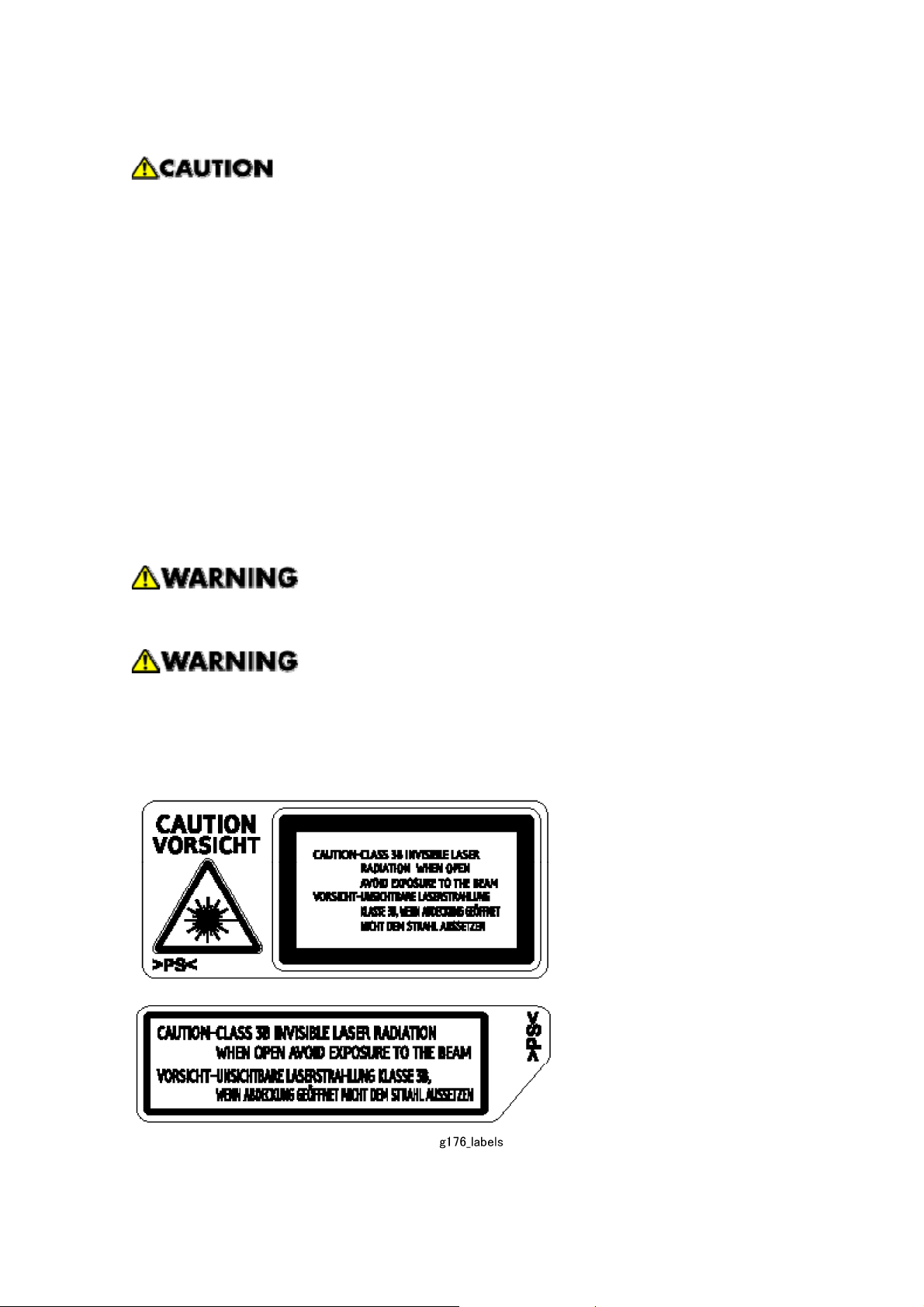
Caution Labels
Conventions and Trademarks
Conventions
Symbol What it means
☛
!
"
#
$
%
Refer to section number
See Core Tech Manual for details
Screw
Connector
E-ring
C-ring
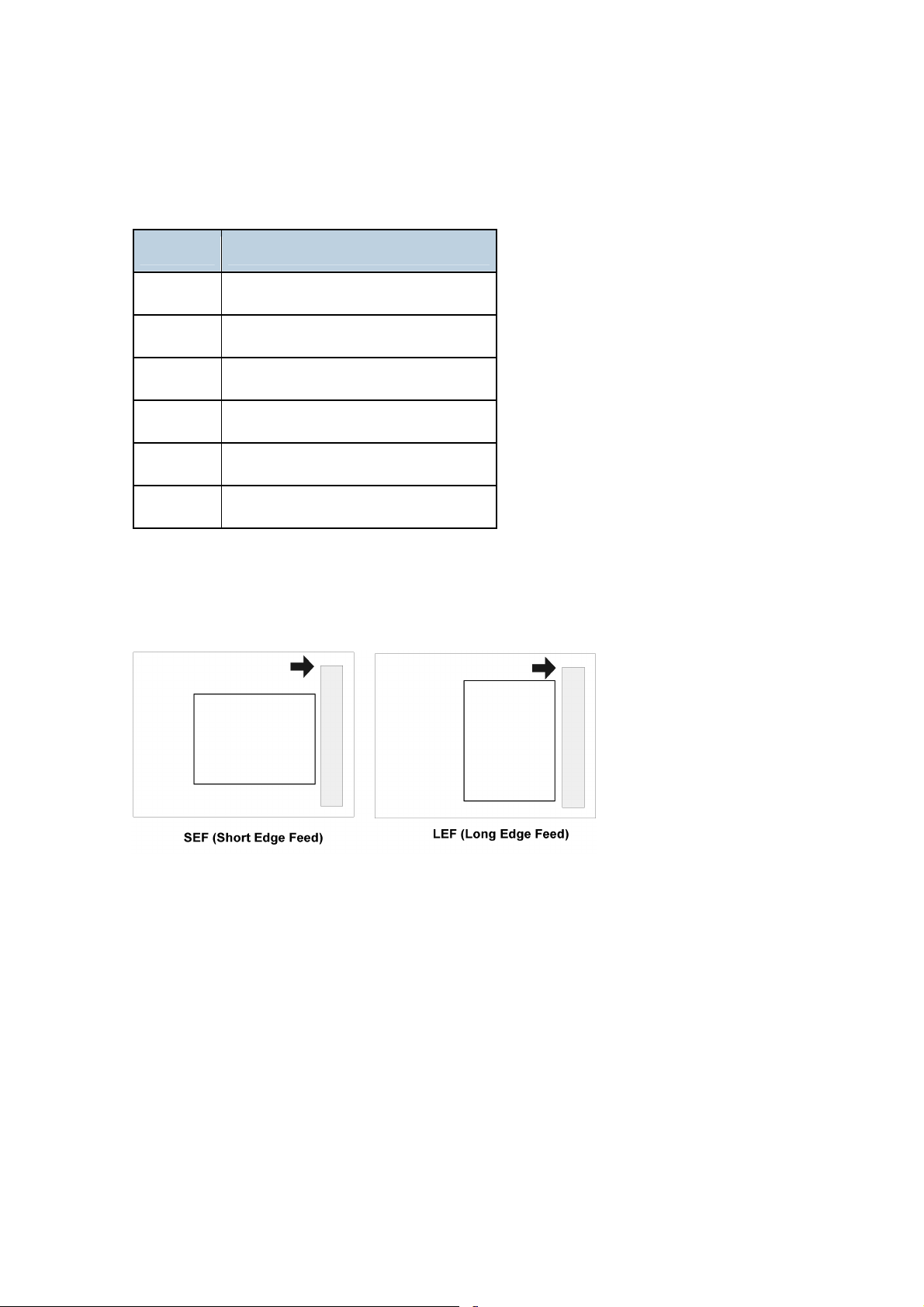
The following notations are used in text to describe the direction of paper feed: lengthwise
and sideways. The annotations “SEF” and “LEF” denote “Short Edge Feed” and “Long
Edge Feed". (The arrows indicate the direction of paper feed.)
Trademarks
Microsoft®, Windows®, and MS-DOS® are registered trademarks of Microsoft Corporation
in the United States and /or other countries.
®
PostScript
®
PCL
Ethernet
PowerPC
Other product names used herein are for identification purposes only and may be
trademarks of their respective companies. We disclaim any and all rights involved with
those marks. This manual uses several symbols and some simple abbreviations.
is a registered trademark of Adobe Systems, Incorporated.
is a registered trademark of Hewlett-Packard Company.
®
is a registered trademark of Xerox Corporation.
®
is a registered trademark of International Business Machines Corporation.


INSTALLATION
SECTION 1 INSTALLATION REVISION HISTORY
Page Date Added/Updated/New
None

1. INSTALLATION
1.1 INSTALLATION REQUIREMENTS
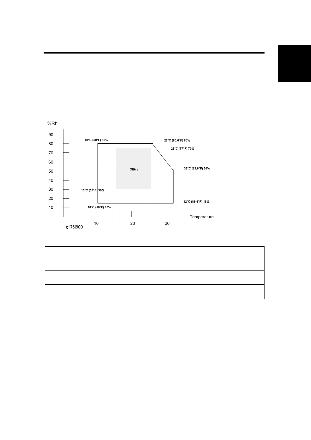
1.1.1 ENVIRONMENT
Installation Requirements
Installation
Temperature/Humidity
Ranges:
Ambient Illumination: Less than 2000 lux (do not expose to direct sunlight).
Ventilation: 3 times/hr/person
1. Avoid areas that are exposed to sudden temperature changes. This includes:
Areas directly exposed to cool air from an air conditioner.
Areas directly exposed to heat from a heater.
2. Do not install this machine in an area where it will be exposed to corrosive gases.
3. Do not install the machine at locations over 2,500 m (8,125 ft.) above sea level.
4. Put the machine on a strong and level base. Inclination on any side should not exceed
5 mm.
5. Do not put the machine where it may be subjected to strong vibrations.
Acceptable: 10C (50F) 15% to 27C (80.6F) 80%
Recommended (Office): 15C (59F) 30% to 25C (77F) 70%
SM 1-1 G176/G177/G176L
Installation Requirements
1.1.2 MACHINE LEVEL
Front to back: Within 5 mm. (0.2 inches) of level.
Right to left: Within 5 mm. (0.2 inches) of level.
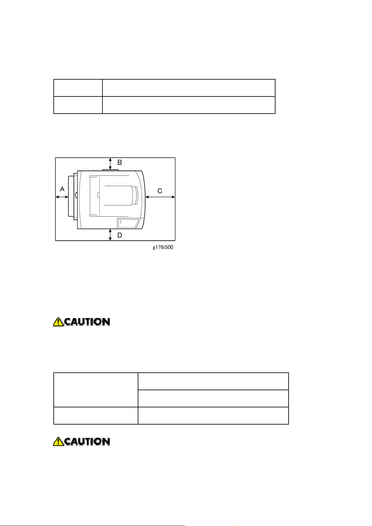
1.1.3 REQUIRED SPACE
Place the machine near the power source, providing the clearance as shown below:
A: Over 10 cm (4 inches)
B: Over 10 cm (4 inches)
C: Over 40 cm (15.8 inches)
D: Over 10 cm (4 inches)
1.1.4 POWER SUPPLY
Make sure the plug is firmly inserted in the outlet.
Avoid multi-wiring.
Be sure to ground the machine.
NA: 120 volts, 60 Hz
Input voltage level
EU: 220-240 volts, 50 Hz/60 Hz
Permitted voltage Fluctuation: ±10 %
Never place anything on the power cord.
G176/G177/G176L 1-2 SM
1.2 MACHINE INSTALLATION
Machine Installation
Refer to the following sections of the Operating Instructions for installation details for all
models.
Installing the Printer Unit: Quick Installation Guide.
Main unit
Connecting the machine to a computer: Quick Installation Guide
Paper Feed Unit G894
Envelope Feeder G362
Duplex Unit G893
Memory Unit Type C 128 MB G331
Memory Unit Type C 256 MB G332
Hardware Guide,
Options
Hard Disk Drive Type 2650 M311
IEEE 802.11b interface Unit Type H G813 *1
Section 2
Installation
IEEE 802.11b Interface Unity Type I G874 *1
Gigabit Ethernet Board Type A G874 *1
VM Card Type D G874
Data Storage Card Type A G874
Data Overwrite Security Unit Type E G874 See next section of this
For more about drivers and other software, see Section 1 of the Software
Drivers
Guide.
*1 These units cannot be installed at the same time.
manual.
SM 1-3 G176/G177/G176L
Data Overwrite Security Unit Installation
1.3 DATA OVERWRITE SECURITY UNIT
INSTALLATION
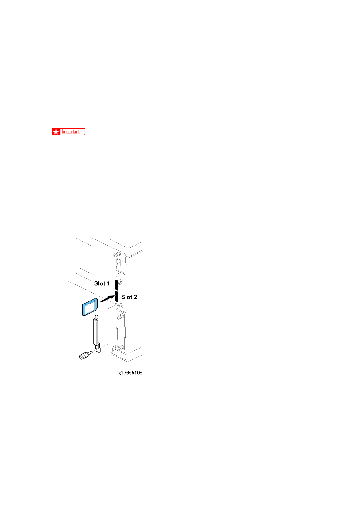
1.3.1 INSTALLATION
The correct number and type for this installation is Type E. Do not attempt to install
any other type (Type C, Type D, for example).
The SD card that holds the DOS application must always reside in SD card slot C2.
(This can be the original SD or another SD card where the DOS (Data Overwrite
Security) application has been moved with SP5873.)
1. If the machine is on, turn off the main power switch.
2. Disconnect the network cable.
3. Turn the main power switch on.
4. Turn the operation switch and main power switch off.
5. Remove the SD card slot cover (x1).
6. Insert the DOS SD card into Slot 2.
7. Reconnect the network cable, if the network is connected to the copier.
8. Turn the main power switch on.
9. Enter the SP mode and do SP5878 and push [#Enter] to enable the DOS application.
10. Go out of the SP mode, turn the operation switch off, then turn the main power switch
off.
G176/G177/G176L 1-4 SM
 Loading...