

Page 1

N.T. 3323A
JA0C
Features of the Scénic JA0C fitted
with F4R engine
For all parts not dealt with in this Technical Note, refer to Workshop Repair Manual MR 312
77 11 294 602
"The repair methods given by the manufacturer in this document are based on the
technical specifications current when it was prepared.
The methods may be modified as a result of changes introduced by the manufacturer
in the production of the various component units and accessories from which his
vehicles are constructed."
MARCH 2000
© RENAULT 2000
EDITION ANGLAISE
All copyrights reserved by Renault.
Copying or translating, in part or in full, of this document or use of the service part
reference numbering system is forbidden without the prior written authority of Renault.
Page 2

Contents
LIFTING
02
Underbody lifts 02-1
07
VALUES AND SETTINGS
Capacities - Grades 07-1
Accessories belt tension 07-3
Procedure for tensioning the timing belt 07-4
Tightening the cylinder head 07-26
Tyres and wheels 07-27
Brakes 07-28
Underbody height 07-29
Front axle angle checking values 07-30
Rear axle angle checking values 07-31
ENGINE AND PERIPHERALS
10
Identification 10-1
Oil pressure 10-2
Engine - gearbox assembly 10-3
Sump 10-10
TOP AND FRONT OF ENGINE
11
Timing belt 11-1
Cylinder head gasket 11-9
Page
ANTIPOLLUTION
14
Fuel vapour rebreathing 14-1
16
STARTING - CHARGING
Alternator 16-1
Starter motor 16-3
INJECTION
17
Technical specifications 17-1
Immobiliser function 17-2
Injection/Air conditioning diagram 17-3
Idle speed correction 17-4
Richness regulation 17-5
Adaptive richness correction 17-7
Camshaft dephaser 17-8
Central coolant management GCTE 17-9
Computer 17-10
Features of the "On Board Diagnostic"
system 17-11
Illumination conditions of the "On Board
Diagnostic" light 17-12
Fault finding conditions 17-13
Combustion misfire fault finding 17-14
Catalytic converter fault finding 17-15
Oxygen sensor fault finding 17-16
Page
FUEL MIXTURE
12
Technical specifications 12-1
Air filter unit 12-4
Inlet manifold 12-5
Injector holder shims 12-6
Exhaust manifold 12-8
COOLING SYSTEM
19
Filling - bleeding 19-1
Diagram 19-2
Radiator 19-3
Water pump 19-4
Suspended engine mounting 19-5
Fuel tank 19-6
Catalytic converter 19-9
Page 3

Contents
CLUTCH
20
Mechanism - Plate 20-1
21
MANUAL GEARBOX
Identification 21-1
Ratios 21-1
Capacity - Lubricants 21-2
Gearbox (Removal - Refitting) 21-3
Differential cover seal 21-10
th
5
gear housing seal 21-12
FINAL DRIVE
26
General - Identification 26-1
Final drive (Removal - Refitting) 26-2
Viscous coupling 26-5
Tapered torque seal 26-6
Input shaft seal 26-8
Transverse driveshaft seal 26-10
Final drive differential cover seal 26-13
TRANSMISSION
29
Page
FRONT AXLE
31
Sub-frame 31-1
33
REAR AXLE
Stabiliser bar 33-1
Shock absorber 33-2
Spring 33-3
Rear suspension arm 33-5
Wheel bearing 33-8
Sub-frame 33-10
STEERING
36
Power assisted steering rack 36-1
Retractable shaft 36-5
MECHANICAL ELEMENT CONTROLS
37
Exploded view 37-1
Clutch transmitter cylinder 37-2
Clutch receiver cylinder 37-4
Clutch control pipes 37-6
Page
Transverse driveshaft 29-1
Longitudinal driveshaft 29-4
ELECTRONICALLY CONTROLLED
38
HYDRAULIC SYSTEM
BOSCH ABS 38-1
Page 4
102
LIFTING
LIFTING
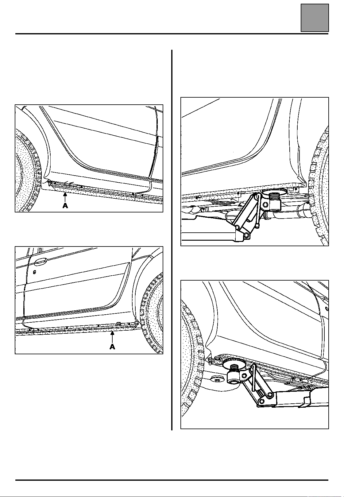
Underbody lifts
Underbody lifts
In order to position the lifting pads under the body
flange, the edges of the valance protector (A) have to
be removed by unclipping them.
Rear protector
02
POSITION OF THE LIFTING PADS
Front
Front protector
18111R
18109S
Rear
18112R
02-1
18110S
Page 5
VALUES AND SETTINGS
VALUES AND SETTINGS
107
Components
Petrol engine
(oil)
Capacity in
litres
(approx.)*
For oil
changes
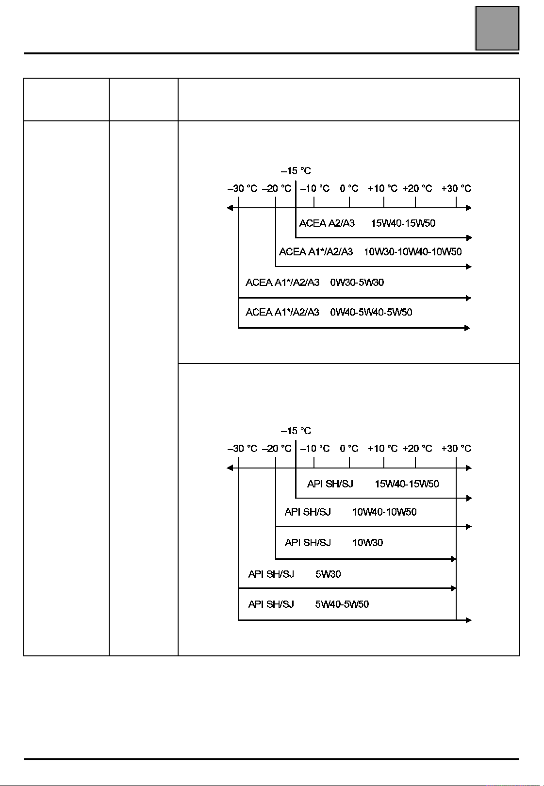
Capacities - Grades
Capacities - Grades
Grade
Countries in the European Union and Turkey
PETROL
07
F4R
4.4
4.55 (1)
Standard ACEA A1-98
* Oil for fuel economy
Other countries
When the lubricants specified for the countries of the European Union are not
available, the following specifications should be used:
PETROL
* Adjust using a dipstick
(1) After replacing the oil filter
Oil for fuel economy:
Standard API SJ-IL SAC GF2
07-1
Page 6

VALUES AND SETTINGS
Components
Gearbox JC7 3.3
Final drive SD1 0.8
Cooling circuit
F4R
Capacity in
litres
7.9
Capacities - Grades
Grade Special notes
All countries: TRANSELF TRX 75 W 80 W
(Standards API GL5 or MIL-L 2105 G or D)
TRANSELF 80 W 90
(to be ordered from ELF)
Glacéol RX
(type D)
Protection to - 20 ˚C ± 2 ˚C for warm, moderate
and cold climates.
Protection to - 37˚C ± 2˚C for very cold climates.
07
07-2
Page 7
WITH
AIRCONDITIONING
VALUES AND SETTINGS
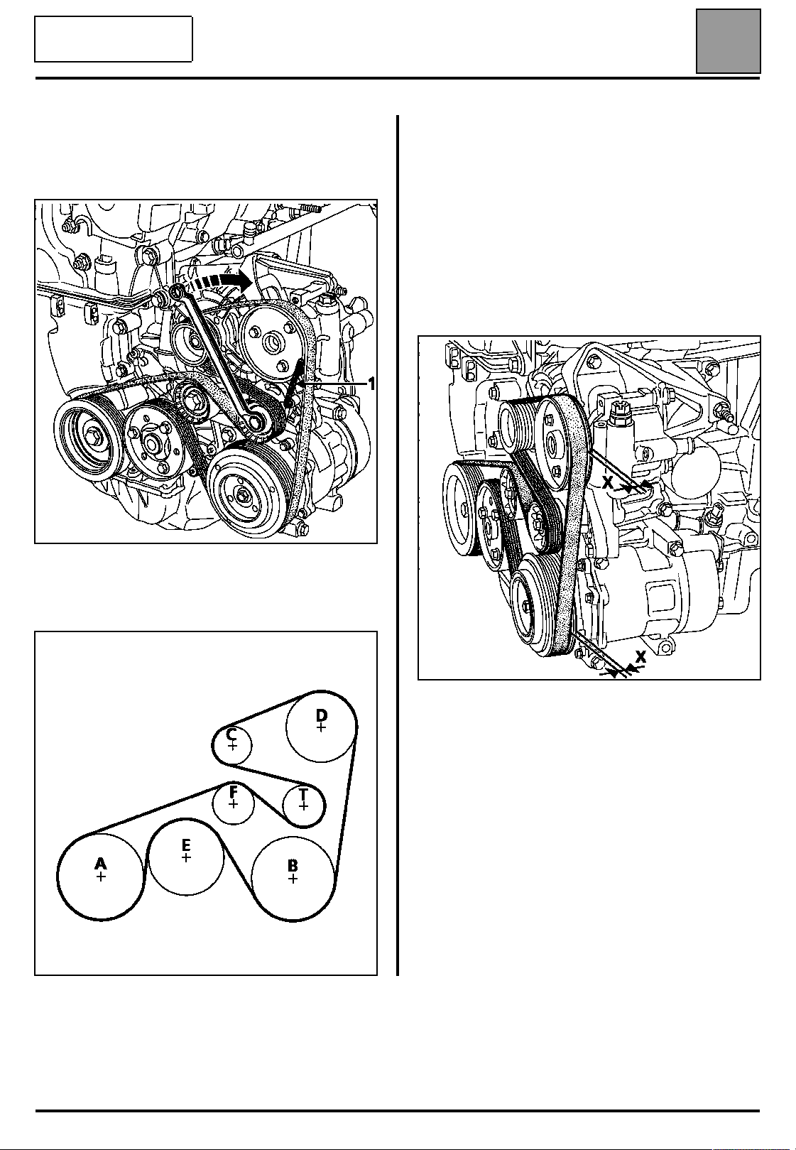
Accessories belt tension
Accessories belt tension
07
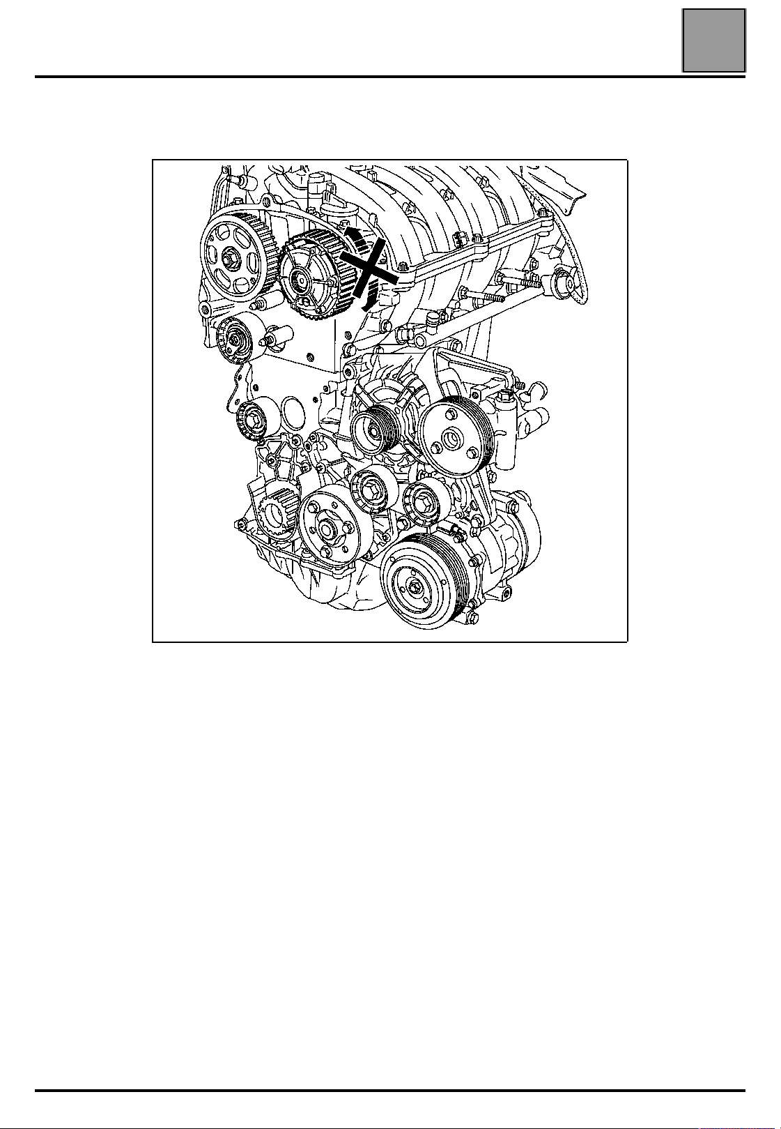
To remove the belt, pivot the automatic belt tensioner
in the direction shown below using a 13 mm angled
ring spanner. Tighten the tensioning roller using a
6 mm Allen key (1).
A Crankshaft
B Air conditioning compressor
C Alternator
D Assisted steering pump
E Water pump
F Fixed roller
T Automatic tensioning roller
When refitting the belt, it is essential to ensure that
the tooth (X) inside the pulleys (timing side)
remains "free".
ALTERNATOR, POWER STEERING AND AIR
CONDITIONING
15111R
15110R
The engine must be turned through two
revolutions in order to position the belt correctly.
15304R
07-3
Page 8

VALUES AND SETTINGS
Timing belt tensioning procedure
Timing belt tensioning procedure
SPECIAL TOOLING REQUIRED
Mot. 799-01 Tool for immobilising pinions on
the toothed timing belt
Mot. 1054 Top Dead Centre pin
Mot. 1453 Engine support
Mot. 1496 Tool for setting the camshaft
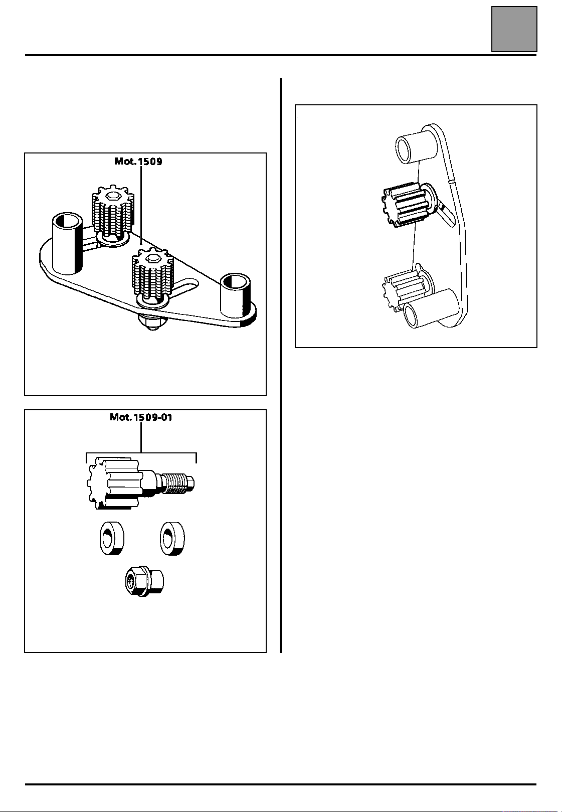
Mot. 1509 Tool for locking the camshaft
pulleys
Mot. 1509-01 Addition to Mot. 1509
Mot. 1517 Tool for fitting inlet camshaft seals
EQUIPMENT REQUIRED
Angular tightening spanner
07
There are two distinct procedures for setting the
timing.
WARNING: the lower timing cover must be fitted
before the crankshaft accessories pulley.
st
1
PROCEDURE
The first procedure is used for replacing all
components which require the exhaust camshaft
pulley and the inlet camshaft dephaser to be
slackened.
During this operation, the following must be
replaced:
– the nut of the exhaust camshaft pulley,
– the bolt of the inlet camshaft dephaser,
– the seal of the camshaft dephaser,
– the seal of the dephaser blanking plate.
07-4
Page 9
VALUES AND SETTINGS
Timing belt tensioning procedure
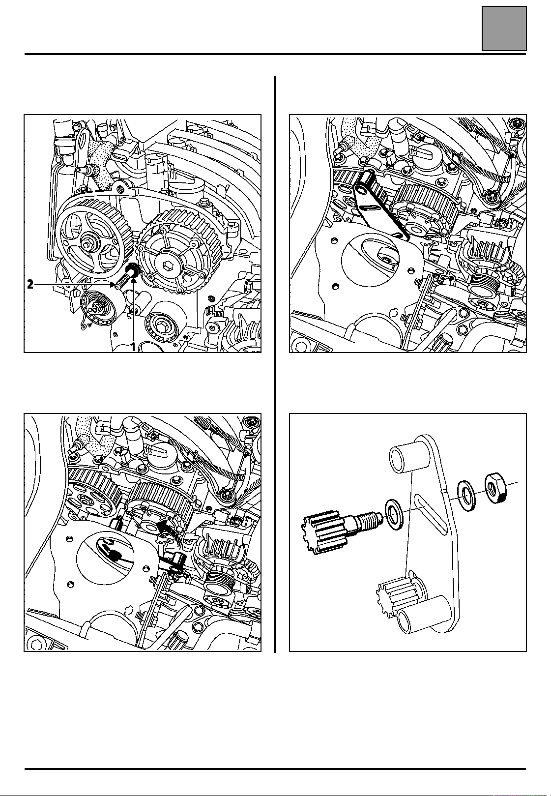
Method for slackening the exhaust camshaft
pulley and the inlet camshaft dephaser.
The operation is performed using tools Mot. 1509
and Mot. 1509-01.
07
Remove the upper toothed pinion from the bracket.
15865R
16017S
16014R
07-5
Page 10
VALUES AND SETTINGS
Timing belt tensioning procedure
Fit:
– the spacer (1) of tool Mot. 1509-01 on the stud (2),
07
Pivot tool Mot. 1509 until the position shown on the
diagram below is reached.
16019R
– tool Mot. 1509 as shown on the diagram below, by
adjusting the position of the engine using engine
support Mot. 1453.
17719-1S
Fit:
– the pinion of tool Mot. 1509-01 (using the two
washers and the nut of tool Mot. 1509),
17719-2S
16018S
07-6
Page 11
VALUES AND SETTINGS
Timing belt tensioning procedure
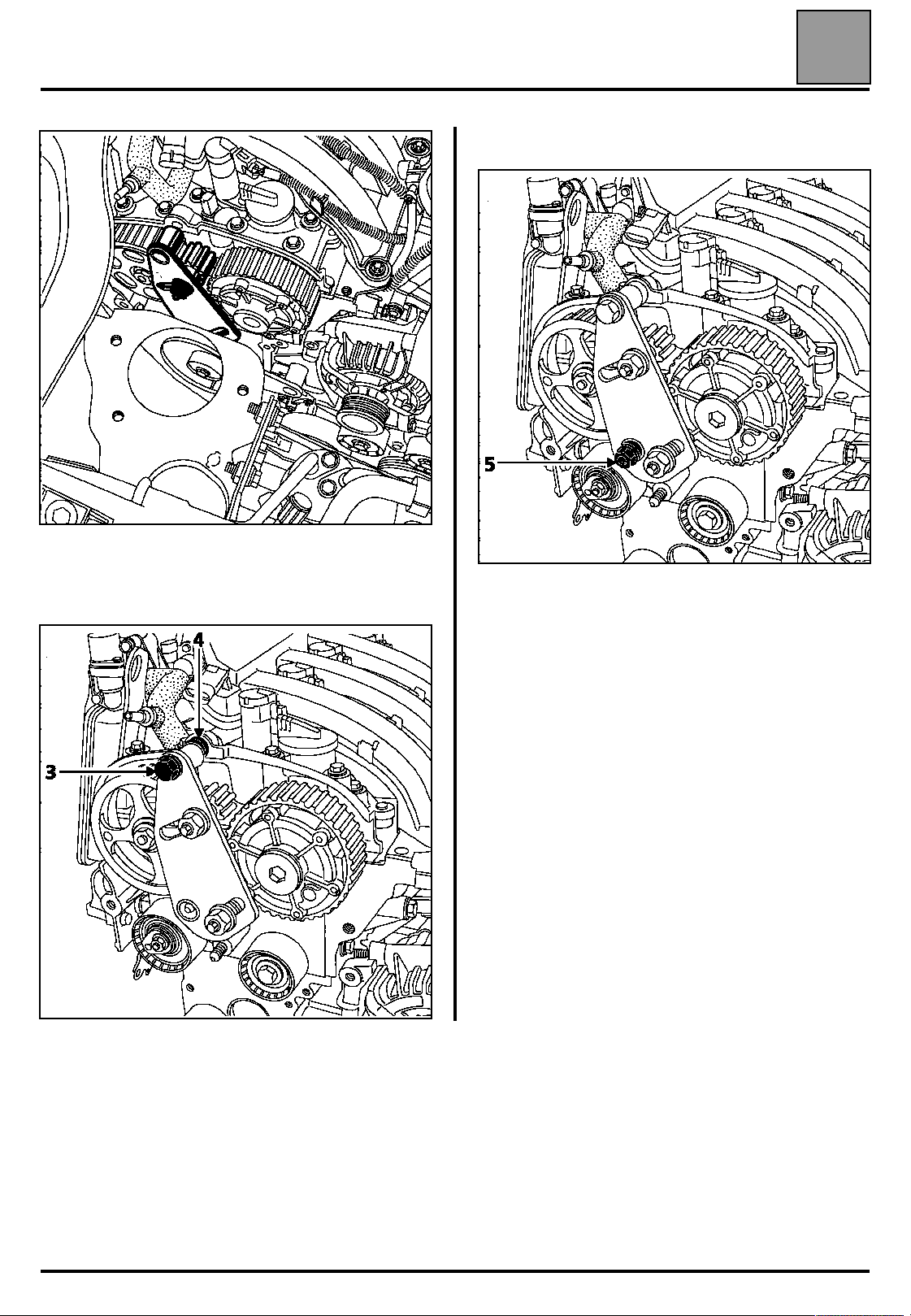
– the shouldered nut (5) of tool Mot. 1509-01.
17719S
07
– the upper bolt (3) whilst positioning the spacer (4) of
tool Mot. 1509-01 between the tool and the camshaft
bearing cap housing (do not lock the bolt).
16019-2R
16019-3R
07-7
Page 12
VALUES AND SETTINGS
Timing belt tensioning procedure
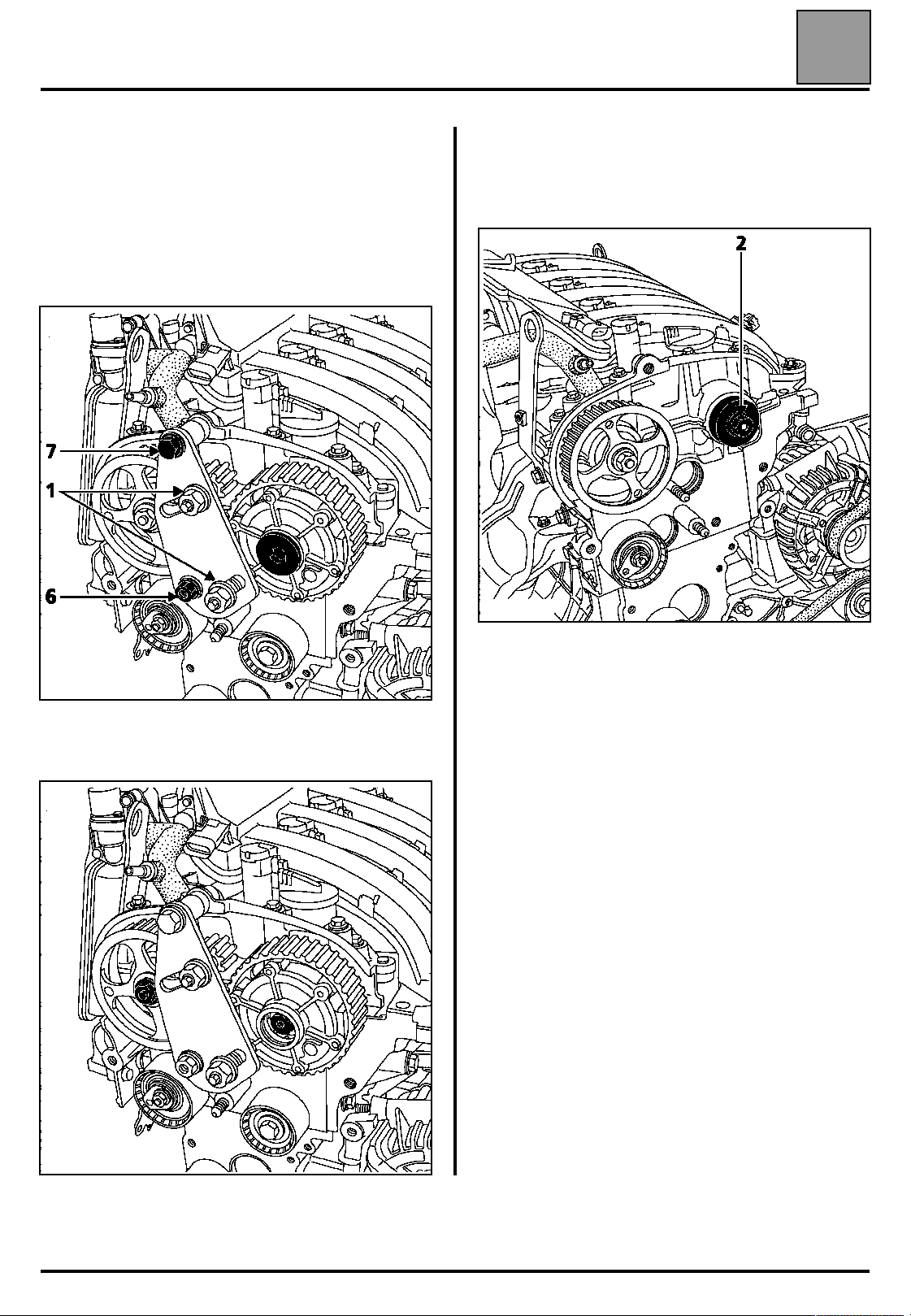
Tighten the shouldered nut (6) and the bolt (7), then
bring the pinions of tool Mot. 1509 into contact with the
camshaft pulleys by tightening the nuts (1) to a torque
of 8 daN.m.
Remove:
– the blanking plate of the inlet camshaft dephaser
using a 14 mm Allen key,
07
Replacing the inlet camshaft dephaser seal
Fit the seal of the inlet camshaft dephaser using tool
Mot. 1517 and the old bolt (2).
– the nut of the exhaust camshaft pulley,
– the bolt of the inlet camshaft dephaser.
16015-1R
NOTE: to use tool Mot. 1517, the hole must be
modified to a diameter of 13 mm.
16019-4R2
16019-5S
07-8
Page 13
VALUES AND SETTINGS
Timing belt tensioning procedure
Adjusting the timing
WARNING:
it is essential to degrease the end of the crankshaft (timing side), the
bore and the bearing faces of the timing pinion, the bearing faces of the
accessories pulley and the ends of the camshafts (timing side), the
bores and the bearing faces of the exhaust camshaft pulley and the inlet
camshaft dephaser; to prevent there being any slip between the timing,
the crankshaft, the exhaust camshaft pulleys and the inlet dephaser,
which may damage the engine.
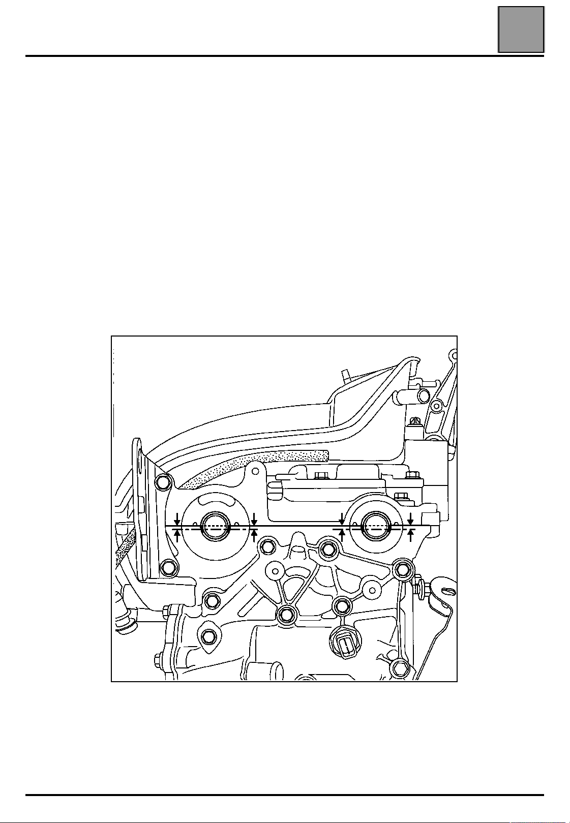
NOTE:
to make it easier to position the grooves horizontally, position the pulley and
dephaser, then tighten the old nut of the pulley and the old bolt of the
dephaser to a torque of 1.5 daN.m MAXIMUM.
Check that the pistons are positioned at mid-stroke (to prevent any
contact between the valves and the pistons).
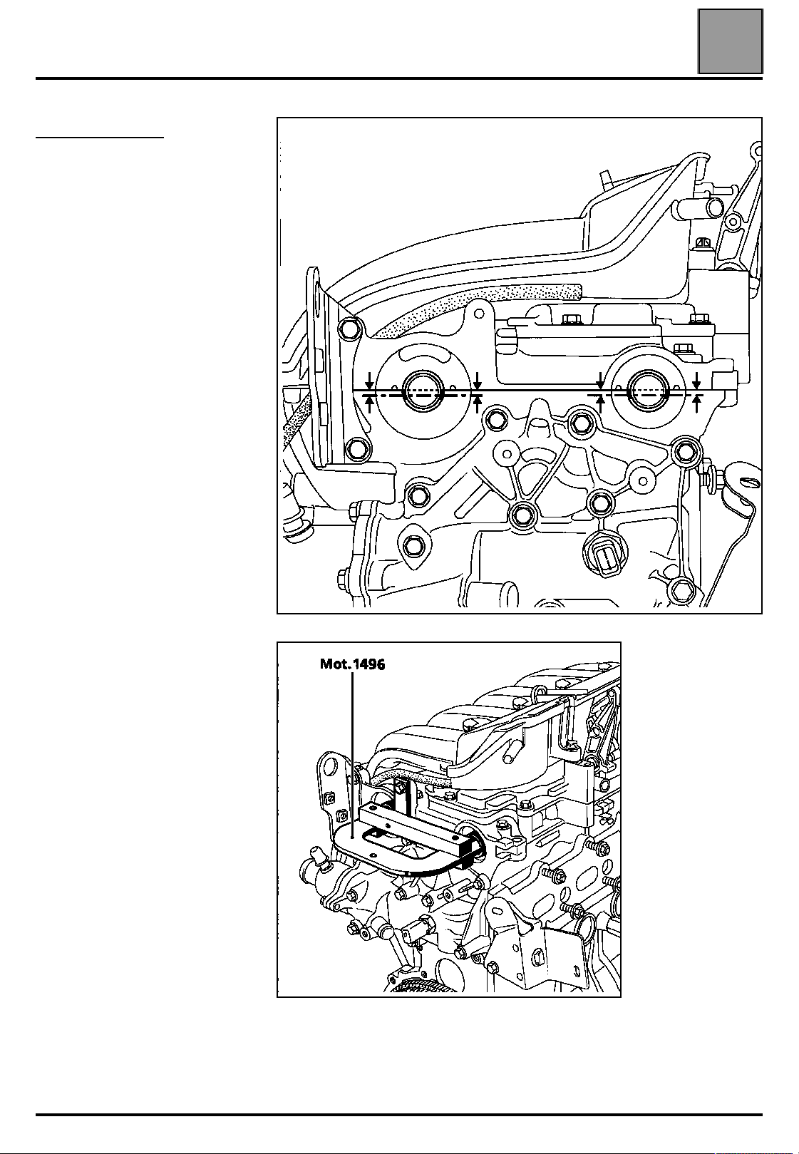
Position the grooves of the camshafts horizontally as shown in the diagram
below (rotating the camshafts using tool Mot. 799-01 if necessary).
07
07-9
15106-1S
Page 14

VALUES AND SETTINGS
Timing belt tensioning procedure
Check that the ring of the camshaft dephaser is correctly locked (no rotation
of the ring to the left or to the right).
07
07-10
Page 15
VALUES AND SETTINGS
Timing belt tensioning procedure
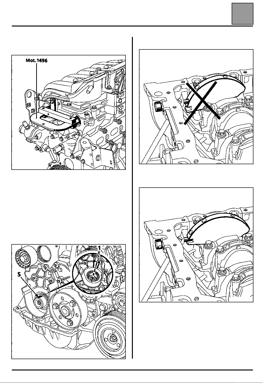
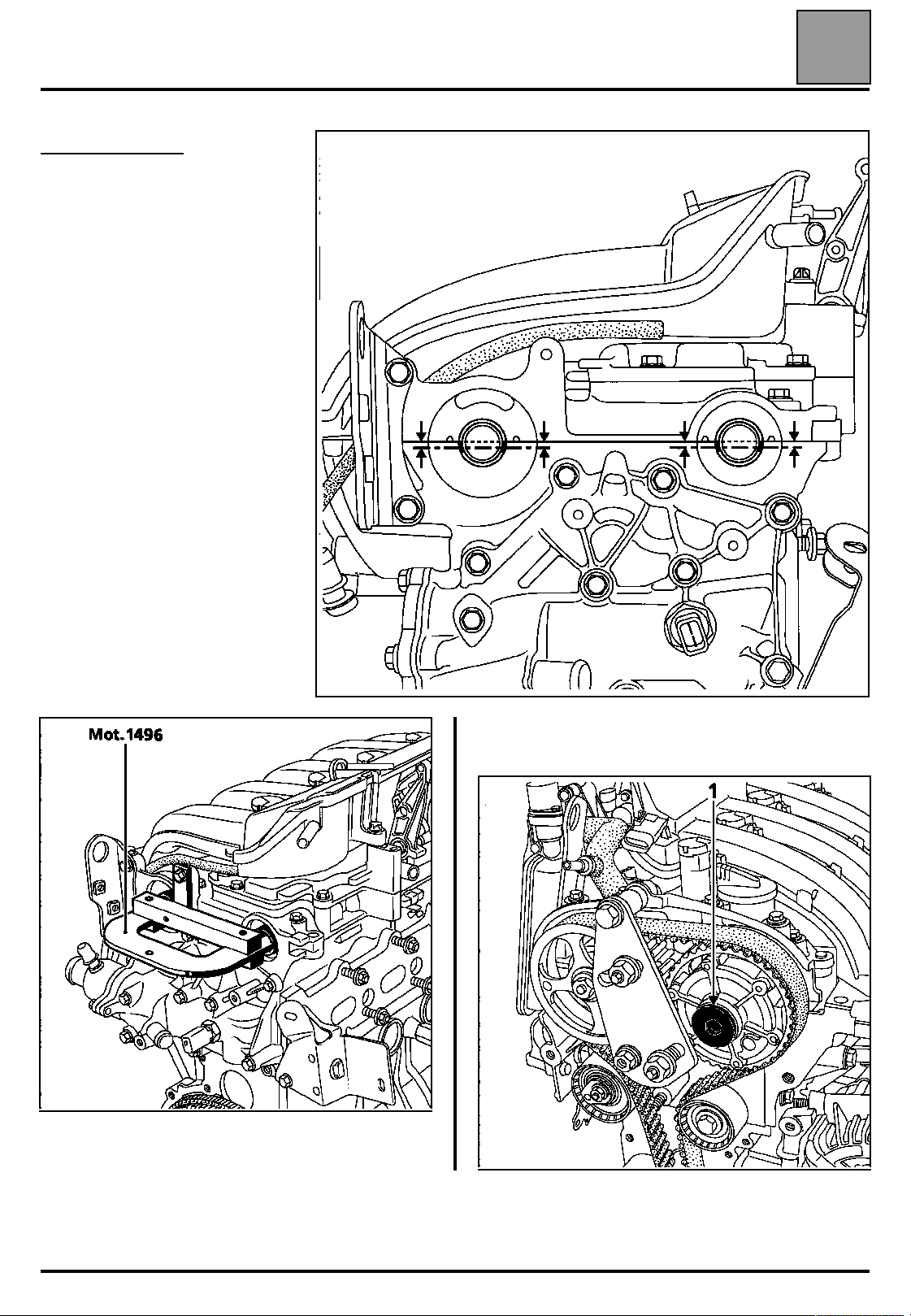
Position tool Mot. 1496, onto the ends of the
camshafts.
07
Incorrect position
15104R
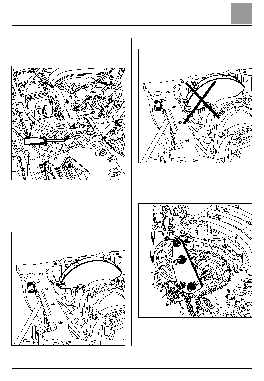
Remove the old nut from the pulley, the old bolt
from the dephaser and replace them with a new
nut and bolt (leave a clearance of 0.5 - 1 mm
between the nut or the bolt and the camshaft
pulleys).
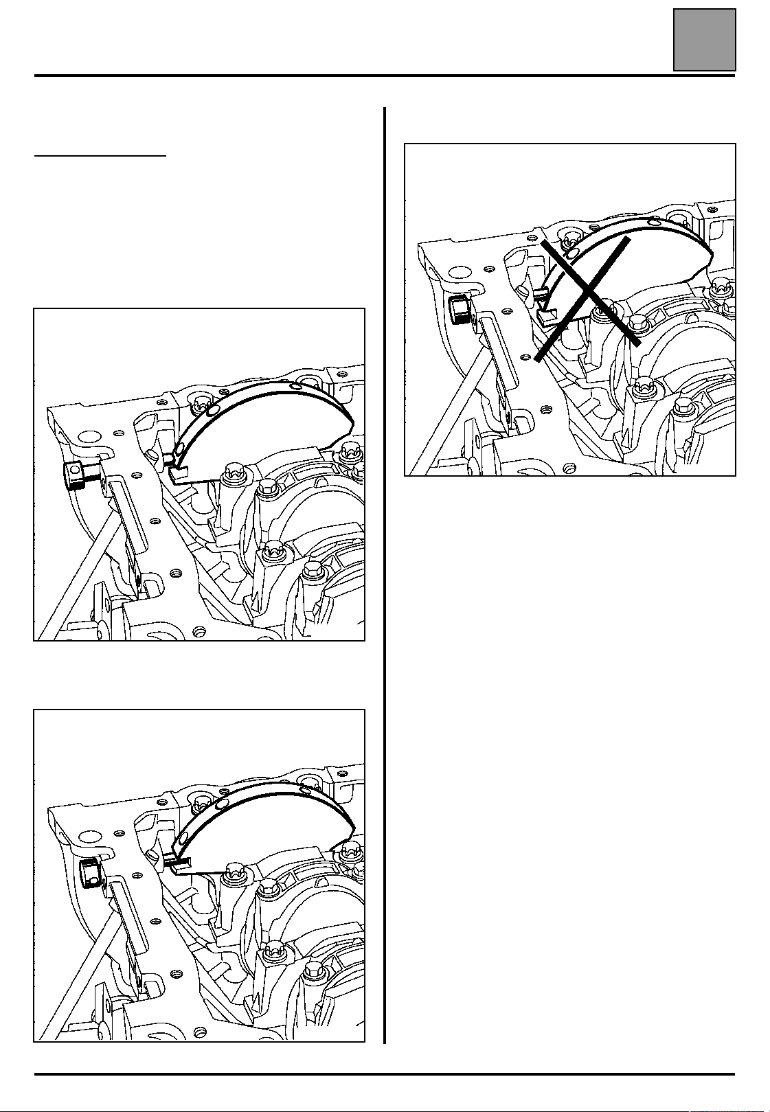
Ensure that the crankshaft is correctly pinned at
Top Dead Centre and not in the balancing hole
(groove (5) of the crankshaft must be positioned in
the middle of the two webs (1) of the crankshaft
closure panel).
15163S
Pinned crankshaft
15114-1R
15163-1S
07-11
Page 16
VALUES AND SETTINGS
Timing belt tensioning procedure
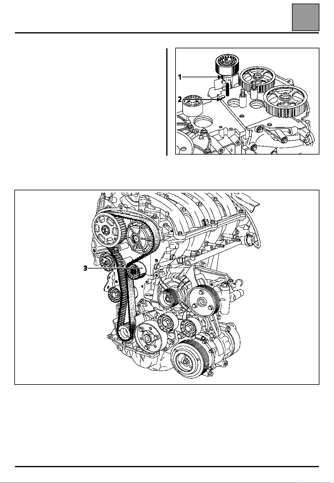
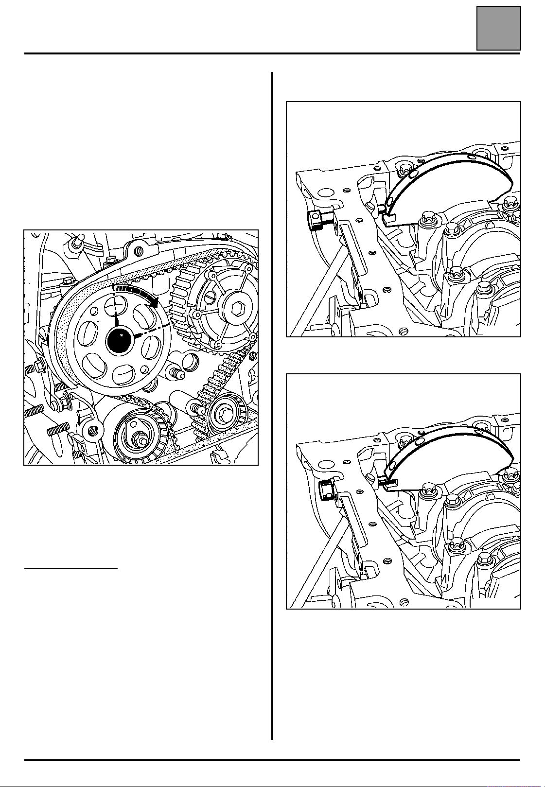
When replacing the timing belt, the tensioning and
fixed rollers must be replaced.
Ensure that the lug (1) of the tensioning roller is
correctly positioned in the groove (2).
Refit:
– the timing belt,
– the fixed roller (3) tightening the mounting bolt to a torque of 4.5 daN.m,
07
15201R
– the lower timing cover without tightening the bolts,
– the crankshaft accessories pulley, pre-tightening the bolt (without locking the bolt, clearance of 2 - 3 mm
between the bolt and the pulley).
NOTE:
– the crankshaft accessories pulley bolt can be reused if the length under its head does not exceed 49.1 mm
(otherwise replace it),
– do not oil the new bolt. However, when reusing the bolt, it must be oiled on the threads and under the head.
07-12
Page 17
VALUES AND SETTINGS
Timing belt tensioning procedure
Belt tension
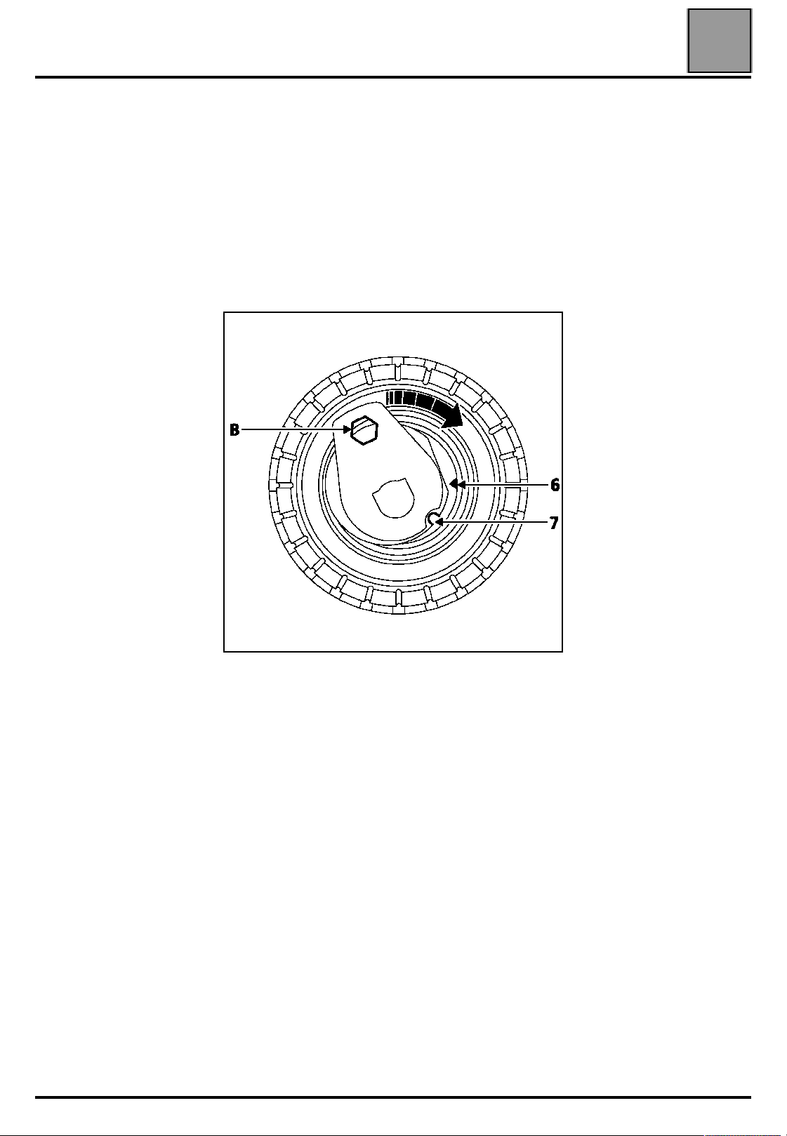
Check that there is always a clearance
of 0.5 - 1 mm between the nut, the bolt and the
camshaft pulleys.
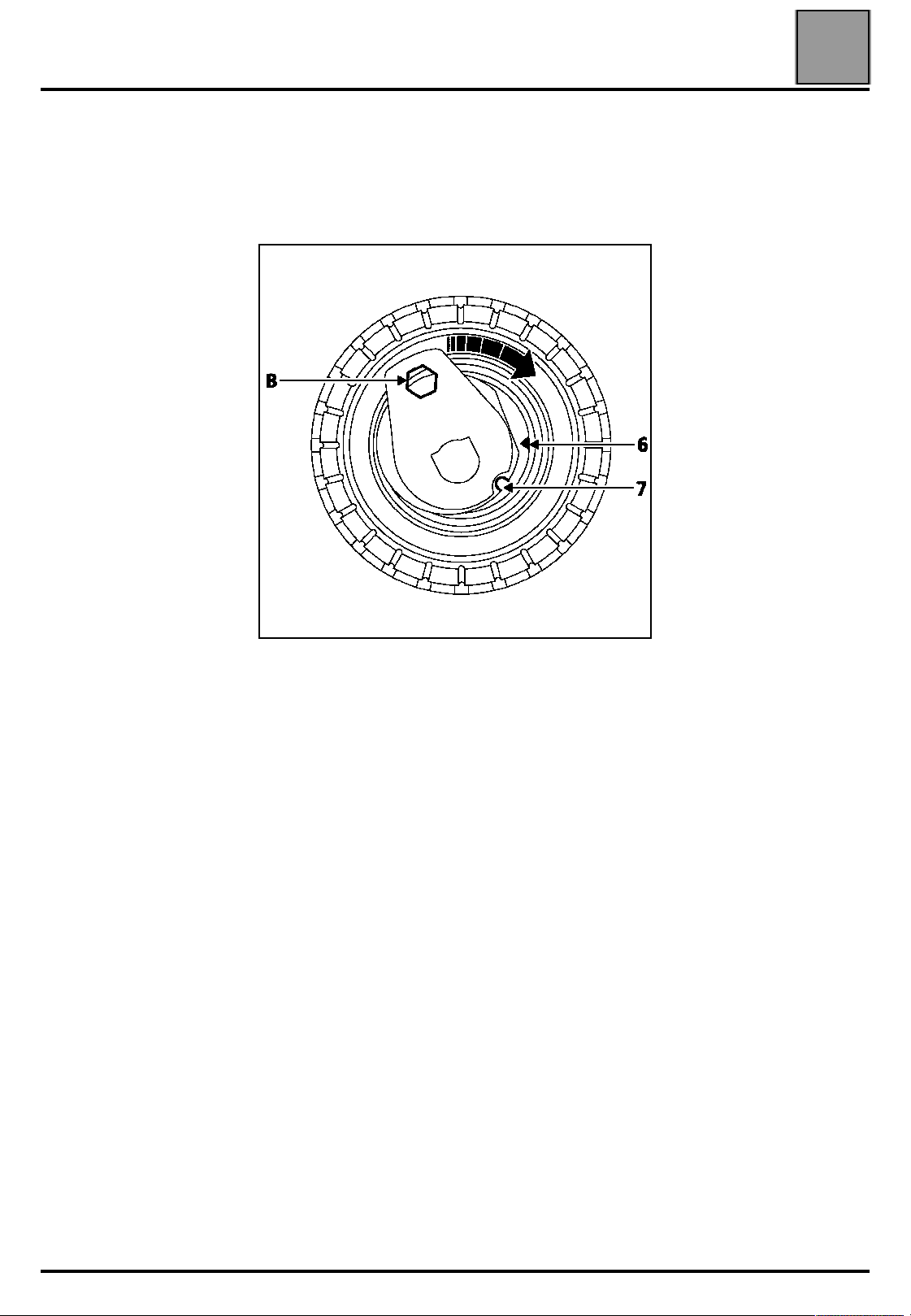
NOTE: do not rotate the tensioning roller in an
anti-clockwise direction.
Align the references (6) and (7) of the tensioning roller
using a 6 mm Allen key at (B).
07
15256R
Pre-tighten the nut of the tensioning roller to a torque
of 0.7 daN.m.
Rotate the timing through six revolutions in a
clockwise direction (timing side) using the exhaust
pulley using tool du Mot. 799-01.
NOTE: check that the nut and the bolt of the camshaft
pulleys do not touch their respective pulleys. To do
this, from time to time, push the camshaft pulleys
against the camshafts.
Alight the references (6) and (7) if necessary,
slackening the nut of the tensioning roller by a
maximum of one turn whilst holding it with a 6 mm
Allen key. Then tighten the nut finally to a torque of
2.8 daN.m.
Tighten the bolt of the accessories crankshaft pulley to
a torque of 2 daN.m (Top Dead Centre pin still
positioned in the crankshaft).
07-13
Page 18
VALUES AND SETTINGS
Timing belt tensioning procedure
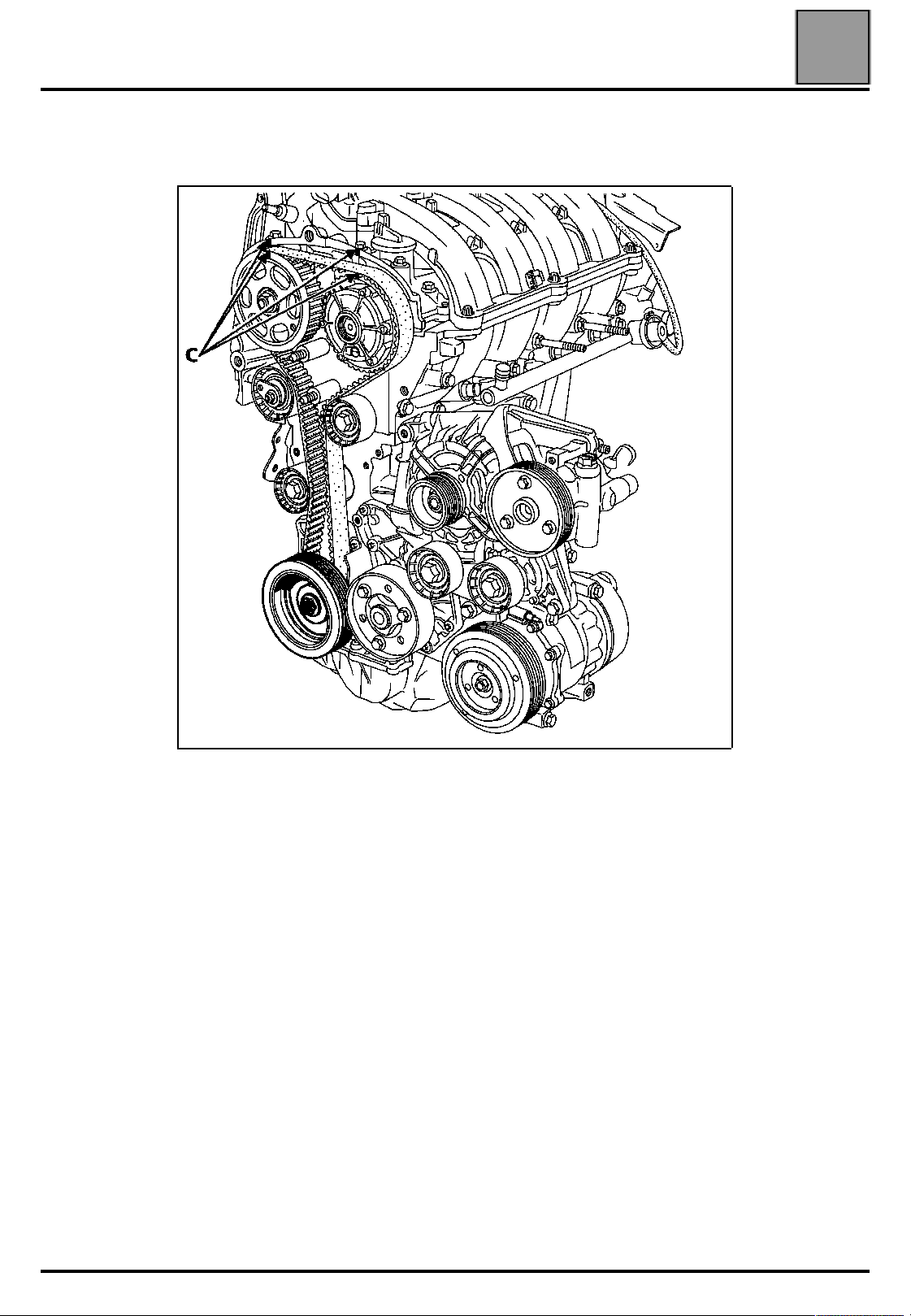
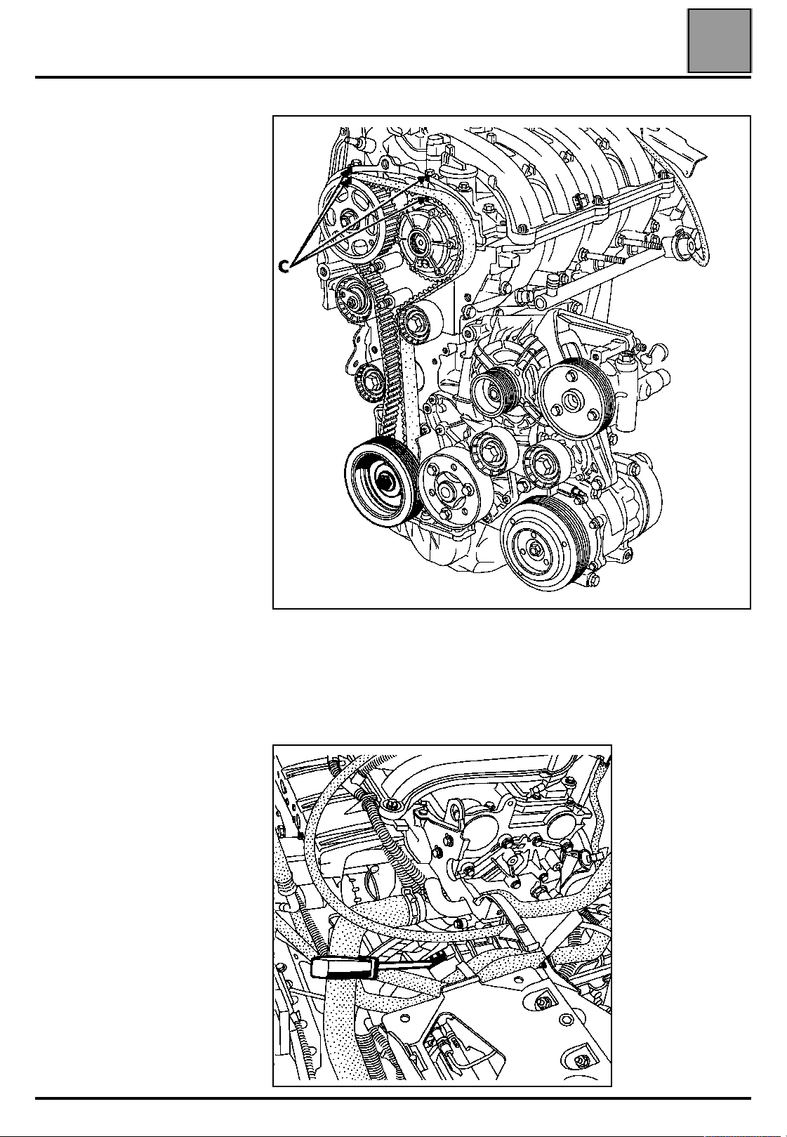
Mark a reference (C) using a pencil between the camshaft pulleys and the
camshaft bearing cap housing.
07
REMOVE THE TOP DEAD CENTRE PIN.
15815-8R
07-14
Page 19
VALUES AND SETTINGS
Timing belt tensioning procedure
Lock the flywheel using a large screwdriver, then turn
the bolt of the accessories crankshaft pulley though an
angle of 115˚ ± 15˚.
07
Incorrect position
17786S
Pin the crankshaft using the references made
previously between the camshaft pulleys and the
camshaft bearing cap housing. These references must
be aligned, which will ensure that the pin is in the
pinning hole and not in the crankshaft balancing hole.
Correct position
15163S
Fit the tool for locking the camshaft pulleys Mot. 1509
fitted with the additional tool Mot. 1509-01.
Follow the same procedure as when removing.
15163-1S
16019-6S
07-15
Page 20
VALUES AND SETTINGS
Timing belt tensioning procedure
Tighten the new bolt of the inlet camshaft dephaser to
a torque of 10 daN.m.
Tighten the new nut of the exhaust camshaft pulley to
a torque of 3 daN.m, then turn through an angle of
90˚ (representing 1/4 of a turn of the nut).
NOTE: as it is not possible to tighten this nut
angularly using the angular tightening spanner,
this operation will be made easier by making
reference points on the pulley and on the nut.
07
Before pinning
17715S
Remove tool Mot. 1496 for setting the camshaft, tool
Mot. 1509 for locking the camshaft pulleys and tool
Mot. 1054, the Top Dead Centre pin.
Checking the timing and the tension
Checking the tension:
Rotate the crankshaft through two revolutions in a
clockwise direction (timing side), and before the end of
the two revolutions (in other words, before the
previously made references are aligned), insert the
Top Dead Centre pin (so as to be between the
balancing hole and the pinning hole) then put the
timing in its setting point.
15163-2S
Pinned crankshaft
15163-1S
Remove the Top Dead Centre pin.
Check that the references of the tensioning roller are
correctly aligned, otherwise repeat the tensioning
procedure. To do this, slacken the nut of the tensioning
roller by a maximum of one turn whilst holding it with a
6 mm Allen key.
07-16
Align the references of the tensioning roller and tighten
the nut finally to a torque of 2.8 daN.m.
Page 21
VALUES AND SETTINGS
Timing belt tensioning procedure
Checking the timing
Ensure that the references of the
tensioning roller are in the correct
position before checking the setting
of the timing.
Fit the Top Dead Centre pin (check
that the references made previously
on the camshaft pulleys are aligned).
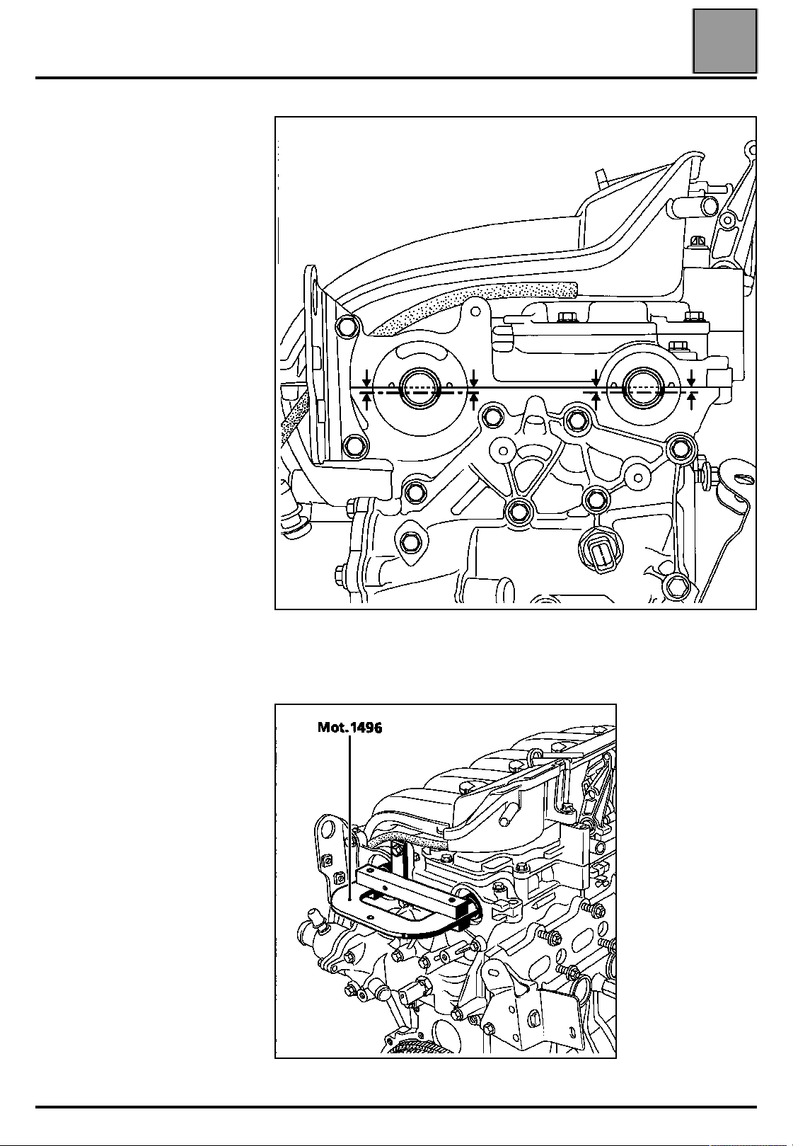
Fit (without forcing) tool Mot. 1496 for
setting the camshaft (the camshaft
grooves must be horizontal and offset
towards the bottom). If the tool cannot
be inserted, the timing setting and
tensioning procedure must be
repeated.
07
15104R
15106-1S
Refit the blanking plate (1) (fitted with a new seal) of
the dephaser tightening it to a torque of 2.5 daN.m
07-17
16019-7R
Page 22
VALUES AND SETTINGS
Timing belt tensioning procedure
2nd PROCEDURE
The second procedure is used for
replacing all components located
on the front of the timing which do
not require the exhaust camshaft
pulley and the inlet camshaft
dephaser to be slackened.
Adjusting the timing
WARNING: it is essential to
degrease the end of the
crankshaft, the bore of the
crankshaft pinion and the bearing
faces of the crankshaft pulley to
prevent any slip between the
timing and the crankshaft which
may damage the engine.
Position the grooves of the camshafts
using tool Mot. 799-01 as shown in
the diagram opposite.
07
Position tool Mot. 1496, onto the ends of the
camshafts.
15106-1S
07-18
15104R
Page 23

VALUES AND SETTINGS
Timing belt tensioning procedure
Ensure that the crankshaft is correctly pinned at
Top Dead Centre and not in the balancing hole
(groove (5) of the crankshaft must be positioned in
the middle of the two webs (1) of the crankshaft
closure panel).
07
Pinned crankshaft
15114-1R
15163-1S
Incorrect position
07-19
15163S
Page 24
VALUES AND SETTINGS
Timing belt tensioning procedure
Check that the ring of the camshaft dephaser is correctly locked (no
rotation of the ring to the left or to the right).
07
15815-6S
07-20
Page 25

VALUES AND SETTINGS
Timing belt tensioning procedure
When replacing the timing belt, the timing
tensioning and fixed rollers must be replaced.
Ensure that the lug (1) of the tensioning roller is
correctly positioned in the groove (2).
Refit:
– the timing belt,
– the fixed roller (3) tightening the mounting bolt to a torque of 4.5 daN.m,
07
15201R
– the lower timing cover without tightening the bolts,
– the crankshaft accessories pulley, pre-tightening the bolt (without locking the bolt, clearance of 2 - 3 mm
between the bolt and the pulley).
NOTE:
– the crankshaft accessories pulley bolt can be reused if the length under its head does not exceed 49.1 mm
(otherwise replace it),
– do not oil the new bolt. However, when reusing the bolt, it must be oiled on the threads and under the head.
07-21
Page 26
VALUES AND SETTINGS
Timing belt tensioning procedure
NOTE: do not rotate the tensioning roller in an
anti-clockwise direction.
Align the references (6) and (7) of the tensioning roller
using a 6 mm Allen key at (B).
07
15256R
Pre-tighten the nut of the tensioning roller to a torque
of 0.7 daN.m.
Tighten the bolt of the accessories crankshaft pulley to
a torque of 2 daN.m (Top Dead Centre pin Mot. 1054
still positioned in the crankshaft).
07-22
Page 27
VALUES AND SETTINGS
Timing belt tensioning procedure
Mark a reference (C) on the ring of
the inlet camshaft dephaser and the
exhaust pulley in relation to the
camshaft bearing cap housing.
07
Remove tool Mot. 1496 for setting the camshaft as
well as the Top Dead Centre pin, tool Mot. 1054.
Tighten the crankshaft pulley bolt to an angle of
115˚± 15˚, locking the flywheel using a large
screwdriver.
15815-8R
07-23
17786S
Page 28
VALUES AND SETTINGS
Timing belt tensioning procedure
Checking the timing and the tension
Checking the tension:
Rotate the crankshaft through two revolutions in a
clockwise direction (timing side). Before the end of the
two revolution (in other words, half a tooth before
the previously made references are aligned), insert
the crankshaft Top Dead Centre pin (so as to be
between the balancing hole and the pinning hole) then
put the timing in its setting point.
07
Incorrect position
Correct position
15163S
Remove the Top Dead Centre pin, tool Mot. 1054.
Check that the references of the tensioning roller are
correctly aligned, otherwise repeat the tensioning
procedure. To do this, slacken the nut of the tensioning
roller by a maximum of one turn whilst holding it with a
6 mm Allen key.
15163-2S
Align the references of the tensioning roller and tighten
the nut finally to a torque of 2.8 daN.m.
15163-1S
07-24
Page 29
VALUES AND SETTINGS
Timing belt tensioning procedure
Checking the timing:
Ensure that the references of the
tensioning roller are in the correct
position before checking the setting
of the timing.
Fit the Top Dead Centre pin (check
that the references made previously
on the camshaft pulleys are aligned).
Fit (without forcing) tool Mot. 1496 for
setting the camshaft (the camshaft
grooves must be horizontal and offset
towards the bottom). If the tool cannot
be inserted, the timing setting and
tensioning procedure must be
repeated.
07
15104R
15106-1S
07-25
Page 30
VALUES AND SETTINGS
Tightening the cylinder head
Tightening the cylinder head
METHOD FOR TIGHTENING THE CYLINDER HEAD
The bolts can be reused if the length under the head does not exceed 118.5 mm (otherwise, replace all the
bolts).
Method for tightening the cylinder head
REMINDER: in order to tighten the bolts correctly, use a syringe to remove any oil which may have entered the
cylinder head mounting bolt holes.
Do not oil the new bolts. However, when reusing the bolts, they must be oiled.
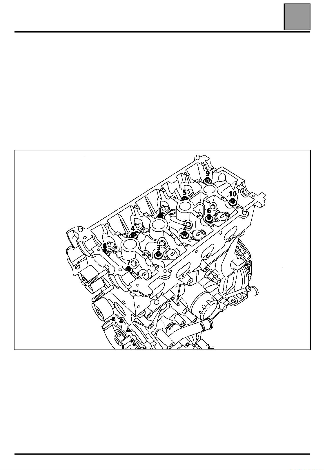
Tighten all the bolts to 2 daN.m in the order recommended below.
07
Check that all the bolts are correctly tightened to 2 daN.m then, bolt by bolt, tighten to an angle of 165˚ ± 6˚.
Do not tighten the cylinder head bolts after applying this procedure.
07-26
15153-1R
Page 31

VALUES AND SETTINGS
Tyres and wheels
Tyres and wheels
Type Rim Tyres
JA0C 6.5 J 16 215/65 R 16 T 2 2
(1) During motorway use with full load.
Tightening torque of the wheel nuts: 10.5 daN.m
Rim run-out: 1.2 mm
07
Cold inflation pressure
(in bars) (1)
Front Rear
07-27
Page 32

VALUES AND SETTINGS
Type
JA0C 24 21.8 11 9.5
Maximum disc warp: 0.07 mm
Brakes
Brakes
Disc thickness
(in mm)
Front Rear
Front Front Normal Max.
Drum diameters or disc thicknesses (in mm)
07
Lining thicknesses (in mm) (including backing)
Type
New Min. New Min.
JA0C 18 6 15 5
Brake fluidFront Rear
SAE J1703
DOT 4
07-28
Page 33

VALUES AND SETTINGS
MEASUREMENT POINTS
Underbody height
Underbody height
07
Dimension H5 is measured from the axis of the
suspension arm.
16368R
07-29
17764R
Page 34

VALUES AND SETTINGS
CASTOR
CAMBER
Front axle angle checking values
Front axle angle checking values
ANGLES VALUES
5˚30′
4˚20′ ±30′
3˚50′
Max. right/left
difference = 1˚
- 0˚00′
- 0˚15′ ±30′
- 0˚30′
POSITION OF
FRONT AXLE
H5-H2 = 60 mm
H5-H2 = 80 mm
H5-H2 = 100 mm
H1-H2 = 100 mm
H1-H2 = 105 mm
H1-H2 = 110 mm
07
ADJUSTMENT
NOT
ADJUSTABLE
NOT
ADJUSTABLE
PIVOT
PARALLELISM
Max. right/left
difference = 1˚
13˚15′
13˚40′ ±30′
14˚00′
Max. right/left
difference = 1˚
(for 2 wheels)
toe-out
+ 0˚8′ ± 3′
+ 0.8 mm ± 0.3 mm
H1-H2 = 100 mm
H1-H2 = 105 mm
H1-H2 = 110 mm
UNLADEN
NOT
ADJUSTABLE
Adjusted by
rotating track
rod sleeves
1 turn= 30′
(3 mm)
POSITION FOR TIGHTENING RUBBER BUSHES
- UNLADEN -
07-30
Page 35

VALUES AND SETTINGS
Rear axle angles checking values
Rear axle angles checking values
ANGLES VALUES
CAMBER
- 0˚55′ ± 15′ UNLADEN
PARALLELISM
(for 2 wheels)
- 25′ ± 25′
Clamp
POSITION OF
REAR AXLE
UNLADEN
07
ADJUSTMENT
NOT
ADJUSTABLE
Adjustable by
eccentric
POSITION FOR TIGHTENING
RUBBER BUSHES
- 2.5 mm ± 2.5 mm
-
UNLADEN
Vehicle with
wheels on the
ground
-
07-31
Page 36

ENGINE AND PERIPHERALS
ENGINE AND PERIPHERALS
110
Identification
Identification
Vehicle type Engine Gearbox
JA0C F4R 744 JC7 1998 82.7 93 9.8/1
Section to be consulted: Mot. F4 and N.T. 3200A.
Capacity
3
)
(cm
Bore
(mm)
Stroke
(mm)
10
Compression
ratio
10-1
Page 37

ENGINE AND PERIPHERALS
Oil pressure
Oil pressure
SPECIAL TOOLING REQUIRED
Mot. 836-05 Kit for checking oil pressure
ESSENTIAL SPECIAL TOOLING
22 mm long socket or pipe spanner
CHECKING
The oil pressure should be checked when the engine
is warm (approximately 80° C).
Contents of kit Mot. 836-05.
10
USE
B + F
Connect the pressure gauge in place of the oil
pressure switch.
Oil pressure
Idling 1 bar
3 000 rpm 3 bar
10-2
87363R1
Page 38

ENGINE AND PERIPHERALS
Engine and gearbox assembly
Engine and gearbox assembly
SPECIAL TOOLING REQUIRED
Mot. 1294-01 Tool for removing windscreen
wiper arms
Mot. 1040-01 Dummy sub-frame for removing
and refitting engine and gearbox
assembly
Mot. 1159 Tool for maintaining engine on
subframe
Mot. 1202 -01
Mot. 1202 -02
Mot. 1233-01 Threaded rods for lowering the
Mot. 1448 Long nose pliers for hose clips
Mot. 1453 Engine support tool
Pliers for hose clips
sub-frame
10
TIGHTENING TORQUES (in daN.m)
Sub-frame front mounting bolts 6.2
Sub-frame rear mounting bolts 10.5
Mounting bolt for front right suspended
mounting cover to engine
Movement limiter mounting bolt 6.2
Mounting nut for rubber engine mounting
pad on front left-hand side member support 6.2
Shock absorber base bolts 18
Brake caliper mounting bolt 4
Steering shaft yoke bolt 3
Sub-frame - side member tie-rod bolts 3
Clutch bleed screw 1
Track rod end nut 3.5
Wheel bolts 9
REMOVAL
Put the vehicle on a two post lift. Refer to Section 02
"Underbody lift" for positioning the lifting pads.
6.2
Remove:
– the battery,
– the engine undertray.
Drain:
– the cooling circuit through the bottom hose of the
radiator,
– the gearbox and the engine (if necessary),
– the coolant circuit (if fitted) using filling equipment.
During this operation, the vehicle must be secured
to the lift with a strap to prevent it from becoming
unbalanced.
Refer to Technical Note 2988A for the strap
positioning procedure.
14893S
10-3
Page 39

ENGINE AND PERIPHERALS
Engine and gearbox assembly
Remove:
– the front wheels along with the mudguard,
– the sub-frame and body tie-rods,
– the mountings (A), as well as the rivets (B) and
remove the lower part of the bumper.
10
– the heat shield (C) as well as the mountings of the
precatalytic converter on the catalytic converter
(secure the exhaust pipe to the body),
17703R
– the mountings (2) of the longitudinal driveshaft and
secure it to the body,
– the gear control (3),
17595R
– the track rod ends,
– the brake calipers (as well as the ABS sensors, if
fitted) and secure them to the suspension springs,
– the shock absorber base bolts,
– the upper mountings of the stabiliser bar tie-rods and
slacken the lower mountings,
– the mountings (1) of the tie-rods,
17537R1
17704R1
– the horns,
– the two mountings of the power assisted steering
hoses on the right hand side of the sub-frame,
– the nut and the eccentric bolt of the steering shaft
yoke, after pushing back the guard.
10-4
Page 40

ENGINE AND PERIPHERALS
Engine and gearbox assembly
SPECIAL NOTES FOR VEHICLES FITTED WITH A
DRIVER'S AIRBAG
WARNING
In order to eliminate any risk of damaging the
rotary switch under the steering wheel, observe
the recommendations below:
Before the steering column and the steering
●
rack are uncoupled, the steering wheel MUST
be immobilised for the duration of the
operation with the wheels straight using a
"steering wheel locking tool".
If there is any doubt regarding the correct
●
alignment of the rotary switch the steering
wheel must be removed so that the alignment
procedure described in the "AIRBAG" section
can be applied.
REMINDER: in this case, only qualified
personnel who have received training may carry
out the operation.
10
– the closure panel of the plenum chamber,
11036R2
– the shock absorber cap protectors,
– the accelerator cable,
– the clutch receiver by removing the clip (C),
Disconnect:
– the oxygen sensor from the catalytic converter
(under the body),
– the connector of the pressure switch.
Unclip the power steering reservoir and release it.
Remove:
– the air resonator,
– the windscreen wiper arms using tool Elé. 1294-01,
– the front grilles,
17707R
– the brake servo vacuum pipe,
– the pipe as well as the connector on the canister,
11020R
10-5
Page 41

ENGINE AND PERIPHERALS
Engine and gearbox assembly
– the hoses on the heater radiator,
– the upper hose of the cooling radiator,
– the battery mounting,
– the mountings of the expansion bottle and release it,
– the relay plate at (5) and disconnect the
connectors (6), (7), (8) and (9) as well as the fuse
holder,
10
Fit the engine retaining tool Mot. 1453 ensuring that
the strap is correctly positioned.
13932R
Remove the suspended engine mounting cover.
16668R1
– the connectors of the fan unit,
– the earth strap on the bulkhead,
– the fuel pipe on the injection rail and unclip it from the
lower valve timing cover,
– the mountings of the air conditioning hoses (if
fitted) on the compressor and the dehydration
canister.
NOTE: plugs must be fitted onto the hoses and
pressure relief valve to prevent moisture from entering
the circuit.
10-6
Page 42

ENGINE AND PERIPHERALS
Engine and gearbox assembly
Insert a wooden block between the gearbox and the
sub-frame.
Remove the nut (1), then tap it with a copper hammer
to release the suspended engine mounting stud.
10
15960R
Fit tool Mot. 1040-01 under the engine sub-frame.
Fit the two tools Mot. 1159 as shown below.
17720R
98755R1
Lower the lift until the tool touches the ground.
Remove the sub-frame mounting bolts and take out
the engine and gearbox assembly by lifting the body.
NOTE: for any operation requiring the engine, gearbox
and sub-frame assembly to be separated, take care to
mark the position of tool Mot. 1159 on the sub-frame.
10-7
Page 43

ENGINE AND PERIPHERALS
Engine and gearbox assembly
REFITTING
Features of the clutch receiver when separating
the engine and gearbox
NB: to avoid damaging the receiver, do not coat
the gearbox output shaft with grease.
NB: to avoid leaks, replace the receiver after
replacing the clutch mechanism.
Add brake fluid to the reservoir.
Bleed the circuit using the bleed screw (D) located on
the link on the receiver.
10
The alignment of the sub-frame with the body will be
made easier by positioning two threaded rods
Mot. 1233-01 in the two front mountings of the subframe on the body.
When lowering the body onto the engine - gearbox
assembly, ensure that the catalytic converter is
refitted.
Tighten the sub-frame mounting bolts to a torque of:
– 6.2 daN.m at the front,
– 10.5 daN.m at the rear.
17707R2
Refill the brake fluid.
IMPORTANT: tighten the bleed to the correct torque
(1 daN.m).
10-8
Page 44

ENGINE AND PERIPHERALS
Engine and gearbox assembly
NOTE:
– bolt (A) is longer than (B) and has a washer,
– follow the tightening order as shown below, ensuring that the reinforcement
mountings (C) are tightened at the same time.
10
Refer to section 19 "Suspended engine mounting" for the tightening
torques of the engine - gearbox supports.
Refitting is the reverse of removal.
Refit the heat shields correctly.
Apply Loctite FRENBLOC to the brake calliper mounting bolts before fitting
and tighten them to the correct torque.
Press the brake pedal several times to bring the pistons into contact with the
brake pads.
Fill:
– the engine and gearbox with oil (if necessary),
– the cooling circuit and bleed it (see section 19 "Filling - bleeding").
Fill the coolant circuit using the filling equipment (if fitted).
10-9
Page 45

ENGINE AND PERIPHERALS
SPECIAL TOOLING REQUIRED
Mot. 1233-01 Threaded rods for lowering the
sub-frame
TIGHTENING TORQUES (in daN.m)
Sub-frame front mounting bolts 6.2
Sub-frame rear mounting bolts 10.5
Sump bolts 1.4
Steering shaft yoke bolt 3
Lower ball joint mounting bolt 6
Engine tie bar bolt 6.2
Sub-frame - side member tie-rod bolts 3
Wheel bolts 9
Sump
Sump
10
Remove:
– the lower ball joint mountings as well as the track rod
ends,
– the sub-frame and body tie-rods,
– the lower mountings of the bumper as well as those
of the left hand mudguard,
– the gear control on the gearbox side,
– the horns,
– the bolt (3), and slacken the engine tie-bar bolt (2),
without removing it,
– the mountings (1) of the tie-rods,
REMOVAL
Put the vehicle on a two post lift. Refer to Section 02
"Underbody lift" for positioning the lifting pads.
Disconnect the battery.
Remove the engine undertray.
Drain the engine.
Remove:
– the front wheels along with the right hand mudguard,
– the nut and the eccentric bolt of the steering shaft
yoke, after pushing back the guard.
WARNING
In order to eliminate any risk of damaging the
rotary switch under the steering wheel, observe
the recommendations below:
Before the steering column and the steering
●
rack are uncoupled, the steering wheel MUST
be immobilised for the duration of the
operation with the wheels straight using a
"steering wheel locking tool".
If there is any doubt regarding the correct
●
alignment of the rotary switch the steering
wheel must be removed so that the alignment
procedure described in the "AIRBAG" section
can be applied.
17537R1
– the upper mountings of the stabiliser bar tie-rod and
slacken the lower mountings,
REMINDER: in this case, only qualified
personnel who have received training may carry
out the operation.
10-10
Page 46

ENGINE AND PERIPHERALS
Sump
– the sub-frame mounting bolts, inserting the threaded rods Mot. 1233-01 as you go.
Release the electrical harness from the sub-frame (left hand side).
Progressively lower the sub-frame using the threaded rods Mot. 1233-01 until the
dimension X
= 7 cm is reached.
1
10
Remove the sump.
10-11
Page 47

ENGINE AND PERIPHERALS
Sump
REFITTING
Put a drop of RHODORSEAL 5661 at (A) (on either
side of bearing N˚ 1), and at (B) (at the intersection of
the crankshaft closure panel and the cylinder block).
10
15159-2R
Refit the sump with a new seal, pre-tightening it to a
torque of 0.8 daN.m, then tighten it finally to a torque
of 1.4 daN.m in the order recommended below.
10-12
15195R
Page 48

TOP AND FRONT OF ENGINE
TOP AND FRONT OF ENGINE
111
Timing belt
Timing belt
SPECIAL TOOLING REQUIRED
Mot. 799 -01 Tool for immobilising pinions on the
toothed timing belt
Mot. 1054 TDC setting pin
Mot. 1453 Engine support tool
Mot. 1487 Tool for fitting inlet camshaft
sealing plug
Mot. 1488 Tool for fitting exhaust camshaft
sealing plug
Mot. 1496 Tool for setting the camshaft
Elé. 1294-01 Tool for removing windscreen wiper
arms
ESSENTIAL SPECIAL TOOLING
Angular tightening spanner
11
TIGHTENING TORQUES (In daN.m and/or °)
Fixed roller bolt 4.5
Crankshaft pulley bolt 2 + 135˚ ± 15˚
Tensioning roller nut 2.8
Mounting bolt for front right hand
suspended engine mounting cover on
engine 6.2
Mounting bolt for the movement limiter of
the front right hand suspended engine
mounting 6.2
Wheel bolts 9
REMOVAL
Put the vehicle on a 2 post lift. Refer to Section 02
"Underbody lift" for positioning the lifting pads.
Remove:
– the front right wheel as well as the mudguard,
– the windscreen wiper arms using tool Elé. 1294-01,
– the front grilles,
11020R
– the closure panel of the plenum chamber,
11 - 1
Page 49

TOP AND FRONT OF ENGINE
Timing belt
– the protector of the right hand shock absorber cap,
11036R2
Position the engine support, tool Mot. 1453 with the
retaining straps.
11
– the accessories belt (see Section 07 "Accessories
belt tension"),
– the plate (3) on the side member,
Remove:
– the suspended engine mounting cover and the
movement limiter,
15837R
– the upper radiator mountings.
Disconnect the connectors (4)
Unclip:
– the electrical harness on the upper timing cover and
separate the assembly,
– the petrol pipe on the intermediate timing housing.
13932R
11 - 2
16669R1
Page 50

TOP AND FRONT OF ENGINE
Timing belt
Remove:
– the camshaft sealing plugs,
11
– the Top Dead Centre pin plug.
15105S
11 - 3
15102-1S
Page 51

TOP AND FRONT OF ENGINE
Timing belt
Adjusting the timing
Rotate the engine in a clockwise direction (timing side) so as to position the
camshaft grooves towards the bottom in an almost horizontal position as
shown on the diagram below. Then insert the Top Dead Centre pin Mot. 1054
so as to be between the balancing hole and the crankshaft setting groove.
11
15163-2S
15106S
11 - 4
Page 52

TOP AND FRONT OF ENGINE
Timing belt
Rotate the engine slightly in the same direction, inserting the pin Mot. 1054
to the setting point.
The grooves of the camshafts must, at the setting point, be horizontal and
offset towards the bottom as shown on the diagram below.
11
15106-1S
Correct position Incorrect position (the pin is in the balancing hole).
15163-1S
15163S
11 - 5
Page 53

TOP AND FRONT OF ENGINE
Timing belt
Remove:
– the crankshaft pulley, locking the flywheel using a
screwdriver,
11
– the intermediate timing housing (1),
– the upper housing (2).
17786S
11 - 6
15815-1R
Page 54

TOP AND FRONT OF ENGINE
Timing belt
Slacken the timing belt by undoing the nut (1) of the tensioning roller.
To remove the timing belt, remove the fixed roller (2) and take care not to
drop the crankshaft pinion (as this does not have a key).
Remove the crankshaft timing pinion.
11
11 - 7
Page 55

TOP AND FRONT OF ENGINE
Timing belt
WARNING: it is essential to degrease the end of
the crankshaft, the bore of the crankshaft pinion
and the bearing faces of the crankshaft pulley to
prevent the timing slipping which may damage the
engine.
REFITTING
When replacing the timing belt, the timing
tensioning and fixed rollers must be replaced.
Refit:
– the timing belt (it is essential to follow the method
described in Section 07 "Tensioning the timing
belt"),
– the accessories belt (see Section 07 "Procedure for
tensioning the accessories belt"),
– the plug of the Top Dead Centre pin, applying a drop
of RHODORSEAL 5661 onto the thread,
– the new sealing plugs:
of the inlet camshaft (Mot. 1487),
●
of the exhaust camshaft (Mot. 1488).
●
11
14890R
– the right hand suspended engine mounting by
tightening it to the correct torque (see Section 19
"Suspended engine mounting").
11 - 8
Page 56

TOP AND FRONT OF ENGINE
Cylinder head gasket
Cylinder head gasket
SPECIAL TOOLING REQUIRED
Mot. 799-01 Tool for locking pinions for
toothed timing belt
Mot. 1054 TDC setting pin
Mot. 1159 Tool for securing engine
Mot. 1202-01
Mot. 1202-02
Mot. 1448 Long nose pliers for hose clips
Mot. 1453 Engine support
Mot. 1487 Tool for fitting inlet camshaft
Mot. 1488 Tool for fitting exhaust camshaft
Mot. 1496 Tool for setting the camshaft
Hose clip pliers
sealing plug
sealing plug
11
Mot. 1509
Mot. 1509-01
Mot. 1512 Tool for fitting exhaust camshaft
Mot. 1513 Tool for fitting the camshaft
Mot. 1517 Tool for fitting inlet camshaft
ESSENTIAL SPECIAL TOOLING
Tool for testing cylinder head
Cylinder head testing equipment
Tool for locking the camshaft
pulleys
seal
dephaser solenoid valve seal
seals
Angular tightening spanner
11 - 9
Page 57

TOP AND FRONT OF ENGINE
Cylinder head gasket
TIGHTENING TORQUES (In daN.m and/or°)
Fixed roller bolt 4.5
Crankshaft pulley bolt 2 + 135˚ ± 15˚
Tensioning roller nut 2.8
Exhaust camshaft pulley nuts 3 + 90˚
Camshaft dephaser bolts 10
Cylinder head bolts 1.2
Oil decanter bolts 1.3
Mounting bolt for front right hand
suspended engine mounting cover on
engine 6.2
Mounting bolt for the movement limiter of
the front right hand suspended engine
mounting 6.2
11
99024R2
Lower inlet manifold bolts 2.1
Coil bolts 1.3
Inlet manifold bolts 0.9
Throttle body bolts 1.5
Air filter unit bolt 0.9
Wheel bolts 9
REMOVAL
Put the vehicle on a 2 post lift. Refer to Section 02
"Underbody lift" for positioning the lifting pads.
Remove:
– the timing belt (see method described in section 11,
"Timing belt").
– the engine undertray.
Drain the cooling circuit (through the lower radiator
hose).
15960R
Remove the two power assisted steering hoses on the
right hand side of the sub-frame,
Position the tools Mot. 1159 as shown below:
11-10
Page 58

TOP AND FRONT OF ENGINE
Cylinder head gasket
Insert a wooden block between the gearbox and the
sub-frame.
Remove the engine support tool Mot. 1453.
Method for slackening the exhaust camshaft
pulley and the inlet camshaft dephaser.
The operation is performed using tools Mot. 1509
and Mot. 1509-01.
11
Preparation of tool Mot. 1509
Remove the upper toothed pinion from the bracket.
15865R
16017S
Fit:
– the spacer (1) of tool Mot. 1509-01 on the stud (2),
16014R
16019R
11-11
Page 59

TOP AND FRONT OF ENGINE
Cylinder head gasket
– tool Mot. 1509 as shown on the diagram below, by
adjusting the position of the engine using engine
support Mot. 1453.
11
Fit:
– the pinion of tool Mot. 1509-01 (reusing the two
washers and the nut of tool Mot. 1509),
17719-2S
Pivot tool Mot. 1509 until the position shown on the
diagram below is reached.
16018S
17719S
17719-1S
11-12
Page 60

TOP AND FRONT OF ENGINE
Cylinder head gasket
– the upper bolt (3) whilst positioning the spacer (4) of
tool Mot. 1509-01 between the tool and the camshaft
bearing cap housing (do not lock the bolt).
11
Tighten the shouldered nut (6) and the bolt (7), then
bring the pinions of tool Mot. 1509 into contact with the
camshaft pulleys by tightening the nuts (1) to a torque
of 8 daN.m.
Remove:
– the blanking plate of the inlet camshaft dephaser
using a 14 mm Allen key,
– the shouldered nut (5) of tool Mot. 1509-01.
16019-2R
16019-4R2
– the nut of the exhaust camshaft pulley,
– the bolt of the inlet camshaft dephaser.
16019-3R
16019-5S
11-13
Page 61

TOP AND FRONT OF ENGINE
Cylinder head gasket
Remove:
– the accelerator cable,
– the power steering reservoir from its support and
release it,
– the injection rail protector,
– the fuel supply pipe on the injection rail and release it.
Disconnect:
– the connector (3) as well as those of the coils,
– the vacuum pipe from the brake servo on the inlet
manifold,
– the air housing at (4).
11
15212S
14843R
NOTE: be careful of the vacuum outlet going from the
inlet manifold to the brake servo. The manifold has to
be replaced if this outlet is broken.
Move the air filter unit to the right in order to remove it.
The air filter unit can pass between the windscreen
aperture, the engine and the brake servo.
11-14
Page 62

TOP AND FRONT OF ENGINE
Cylinder head gasket
Remove:
– the stays (A),
11
17706R2
11-15
Page 63

TOP AND FRONT OF ENGINE
Cylinder head gasket
– the mountings of the catalytic converter, release it from the exhaust manifold and secure it to the exhaust pipe,
– the throttle body at (5),
– the oxygen sensor connector of the catalytic converter,
– the lifting bracket (6),
– the air distributor,
11
15149R
11-16
Page 64

TOP AND FRONT OF ENGINE
– the coils,
– the oil decanter,
Cylinder head gasket
11
15150-1S
11-17
Page 65

TOP AND FRONT OF ENGINE
Cylinder head gasket
– the lifting bracket on the flywheel side,
– the bolts of the cylinder head cover then release it vertically by tapping on
the "lugs" at (1) using a copper hammer and lever it using a screwdriver at
(2) (protect the screwdriver to avoid damaging the aluminium surfaces).
11
11-18
Page 66

TOP AND FRONT OF ENGINE
Cylinder head gasket
– the camshafts as well as the valve rockers,
– the hoses on the cylinder head water outlet housing
as well as the coolant temperature sensor connector,
– the mountings of the electrical harness bracket at
(10),
11
14889R1
11-19
Page 67

TOP AND FRONT OF ENGINE
– the cylinder head.
Cylinder head gasket
11
CLEANING
It is very important not to scratch the gasket faces
of all aluminium components.
Use the Décapjoint product to dissolve any part of the
gasket which remains attached.
It is recommended that gloves are worn during the
following operation:
apply the product to the part to be cleaned; wait for
about ten minutes, then remove it using a wooden
spatula.
We must draw your attention to the care which
must be taken during this operation, to prevent
any foreign bodies from being introduced into the
oil channels (channels located in the cylinder
block and in the cylinder head).
15153-1S
CHECKING THE GASKET FACE
Check that there is no gasket face bow.
Maximum deformation: 0.05 mm.
No regrinding of the cylinder head is permitted.
Check the cylinder head for cracks.
11-20
Page 68

TOP AND FRONT OF ENGINE
Cylinder head gasket
REFITTING
When dismantling and refitting the cylinder head,
please comply with the following points:
– It is important to re-prime the hydraulic tappets
as these may become drained after a long time.
To check whether they need repriming, press the
top of the tappet at (A) with your thumb and if the
tappet piston can be pressed down, submerge
the tappet in a container filled with diesel then
refit them.
11
14499R2
11-21
Page 69

TOP AND FRONT OF ENGINE
Cylinder head gasket
– Check:
that the exhaust heat shield is correctly positioned between the oxygen sensor and the manifold (so as
●
to prevent a chimney effect which might destroy the wiring of the upstream sensor),
the alignment (A) between the lower inlet manifold and the cylinder head (timing side), ensuring that the
●
tabs (B) are correctly touching those of the cylinder head cover.
11
The lower inlet manifold must be tightened to a torque
of 2.1 daN.m.
Position the pistons at mid-stroke to prevent any
contact with the valves when refitting the camshafts.
Position the cylinder head gasket then the cylinder
head.
Check the bolts then tighten the cylinder head (see
Section 07 "Tightening the cylinder head").
15148R
15154S
11-22
Page 70

TOP AND FRONT OF ENGINE
Cylinder head gasket
Refit:
– the valve rockers,
– the camshafts by oiling the bearings.
WARNING: do not put oil on the gasket face of the
cylinder head cover.
The camshafts can be identified by the pulley
mountings.
Detail of the pulley mountings:
F exhaust camshaft,
G inlet camshaft.
11
15152R
11-23
Page 71

TOP AND FRONT OF ENGINE
Cylinder head gasket
Position the grooves of the camshafts as shown in the diagram below.
11
NOTE: the gasket faces must be clean, dry and
free from grease (avoid finger marks).
Apply Loctite 518 using a stipple roller to the gasket
face of the cylinder head cover until it turns reddish in
colour.
15106-1S
14517S
11-24
Page 72

TOP AND FRONT OF ENGINE
Cylinder head gasket
Fit the cylinder head cover tightening it to the correct torque.
Tightening procedure
Assembly
Operation n˚ 1 22-23-20-13 - 0.8
Operation n˚ 2
Operation n˚ 3 - 22-23-20-13 -
Operation n˚ 4 22-23-20-13 - 1.2
Bolt tightening
order
1 to 12
14 to 19
21 and 24
Bolt slackening
order
- 1.2
Tightening torques
11
(in daN.m)
11-25
14497-4R1
Page 73

TOP AND FRONT OF ENGINE
Cylinder head gasket
NOTE: the gasket faces must be clean, dry and free from grease (avoid
finger marks).
Apply Loctite 518 using a stipple roller to the gasket face of the oil decanter
until it turns reddish in colour.
14516S
11
Fit the oil decanter and tighten it to a torque of 1.3 daN.m in the recommended order.
11-26
15150-1R
Page 74

TOP AND FRONT OF ENGINE
Cylinder head gasket
The seal of the control solenoid valve is replaced using
tool Mot. 1513.
11
16016R
11-27
Page 75

TOP AND FRONT OF ENGINE
Cylinder head gasket
Refit:
– the coils, tightening them to a torque of 1.3 daN.m,
– the inlet manifold (fitted with new seals), tightening it to a torque of 0.9 daN.m in the recommended order,
11
– the throttle body, tightening the bolts (A) to a torque of 1.5 daN.m,
– the air filter unit, tightening the bolts to a torque of 0.9 daN.m,
15149R1
11-28
Page 76

TOP AND FRONT OF ENGINE
Cylinder head gasket
Replacing the camshaft seals
Fit the seal of the exhaust camshaft dephaser using
tool Mot. 1512, using the old nut (1).
11
Adjusting the timing
WARNING: it is essential to degrease the tip of the
crankshaft, the bore of the timing pinion, the
bearing faces of the pulley as well as the ends of
the camshafts (timing side) and the bores of the
camshaft pinions to prevent the timing from
slipping which may damage the engine.
Refit:
– the timing belt (the method described in Section 07
"Timing belt tensioning procedure" must be
complied with),
– the accessories belt (see Section 07 "Accessories
belt"),
– the new sealing plugs:
of the inlet camshaft (Mot. 1487),
●
of the exhaust camshaft (Mot. 1488).
●
16015R
Fit the seal of the inlet camshaft dephaser using tool
Mot. 1517 and the old bolt (2).
16015-1R
NOTE: to use tool Mot. 1517, the hole must be
modified to a diameter of 13 mm.
14890R
– the right hand suspended engine mounting by
tightening it to the correct torque (see Section 19
"Suspended engine mounting").
Refitting is the reverse of removal.
Fill and bleed the cooling circuit, (see section 19
"Filling and Bleeding").
11-29
Page 77

FUEL MIXTURE
FUEL MIXTURE
112
Specifications
Specifications
Engine
Vehicle Gearbox
Type Suffix
JA0C JC7 F4R 744 82.7 93 1998 9.8/1
Engine
Engine
speed
Type Index CO (%) (1)
(rpm)
Bore
(mm)
Stroke
(mm)
Tests at idle speed*
Pollutant emission **
CO
(%)
2
Cubic
capacity
3
(cm
)
HC (ppm) Lambda (λ)
Ratio
Catalytic
converter
◊ C79
◊ C134
(minimum octane
Euro 2000
Fuel***
rating)
12
Depollution
standard
F4R 744 750 0.5 max 14.5 min 100 max 0.97<λ<1.03 Unleaded (OR 95)
(1) at 2500 rpm, CO must be a maximum of 0.3
At a coolant temperature greater than 80 ˚C and after a coolant engine speed of 2 500 rpm, for about
*
30 seconds. Test to be carried out after return to idle speed.
For legal values refer to your country specification.
**
***
OR 91 unleaded compatible.
Temperature in °C (± 1°)- 10 25 50 80 110
Air Temperature Sensor
Type "Negative Temperature
Coefficient" Resistance in Ohms
Air Temperature Sensor
Type "Negative Temperature
Coefficient" Resistance in Ohms
10 450 to 8 525 2 120 to 1 880 860 to 760 - -
- 2 360 to 2 140 770 to 850 275 to 290 112 to 117
12-1
Page 78

FUEL MIXTURE
Specifications
DESCRIPTION BRAND/TYPE SPECIAL NOTES
Computer
Injection - Sequential multipoint
Stepper motor PHILIPS Resistance: 53 ± 5 Ω at ambient temperature
Throttle potentiometer CTS
Magnetic sensor
(TDC and engine speed)
SIEMENS
"SIRIUS"
ELECTRIFIL
or
SIEMENS
90 tracks
Incorporate in throttle housing
Track resistance: 1 200 ± 240 Ω
Cursor resistance < 1 050 Ω
Track PL PF
A - B
A - C
B - C
Incorporated connector
Resistance = 200 to 270 Ω
1, 250 Ω
1, 245 Ω
2, 230 Ω
1, 250 Ω
2, 230 Ω
1, 245 Ω
12
Canister solenoid valve SAGEM
Injector
Air sensor JAEGER
Coolant sensor JAEGER
Pressure sensor
Pinking sensor SAGEM
Oxygen sensors
(Upstream and Downstream)
MAGNETI-
MARELLI PICO
DELCO
ELECTRONICS
BOSCH
Integrated into the canister
Resistance: 26 ± 4 Ω at 23 ˚C
Resistance: 14.5 Ω
Start of leak: 0.7 cm
CTN (see table)
Resistance: 2 500 Ω at 20 ˚C
CTN (see table)
Resistance: 3 500 Ω at 20 ˚C
Piezoelectric type
Replace the seal each time it is removed
Piezoelectric type
Tightening torque: 2 daN.m
Heater resistance
R ≈ 9 Ω at ambient temperature
Rich mixture = 840 mV ± 70
Lean mixture = 20 mV ± 50
3
/min maxi
12-2
Page 79

FUEL MIXTURE
Specifications
DESCRIPTION BRAND/TYPE SPECIAL NOTES
NIPPONDENSO
Ignition coil'
SAGEM
Spark plugs
Inlet manifold pressure - At idling speed: 300 ± 40 mb
Exhaust counter-pressure -
RC 82 YCL
(Champion)
Primary resistance: 0.48 - 0.52 Ω
Secondary resistance: 5.8 - 8.5 KΩ
Primary resistance: 0.52 - 0.56 Ω
Secondary resistance: 9 - 12.5 KΩ
Tightening torque: 2.5 to 3 daN.m
1 500 rpm.
3 000 rpm
4 500 rpm.
5 500 rpm.
upstream of the
pre-catalytic
converter
30
108
211
321
12
downstream of
the pre-catalytic
converter
23
84
153
266
Submerged feed pump
Pressure regulator -
Camshaft dephaser solenoid
valve
Coolant pressure sensor. -
BOSCH
or WALBRO
AISIN
Flow read: 80 - 100 litres/hour min.
Regulated pressure
Circuit without return: 3.5 ± 0.2 bars
"All or nothing" solenoid valve
Resistance: 7.1 ± 0.5 Ω
For air conditioning computer incorporated into injection
computer operation
12-3
Page 80

FUEL MIXTURE
Air filter unit.
Air filter unit.
SPECIAL TOOLING REQUIRED
Elé. 1294-01 Tool for removing windscreen
wiper arms
TIGHTENING TORQUES (in daN.m)
Air filter unit bolt 0.9
REMOVAL
Disconnect the battery.
Remove:
– the windscreen wiper arms using tool Elé. 1294-01,
– the plenum chamber panel,
12
– the air resonator,
– the brake servo vacuum pipe (manifold side),
– the mounting bolts of the air filter unit (3).
– the bulkhead plate,
11020R
11036R2
14843R1
Disconnect:
– the actuator (1),
– the fuel vapour rebreathing pipe (2).
Move the air filter unit to the right in order to remove it.
The air filter unit can pass between the windscreen
aperture, the engine and the brake servo.
REFITTING
Refitting is the reverse of removal.
NOTE: be careful of the vacuum outlet going from the
exhaust manifold to the brake servo. The inlet manifold
has to be replaced if this outlet is broken.
12-4
Page 81

FUEL MIXTURE
Inlet manifold
Inlet manifold
TIGHTENING TORQUES (in daN.m)
Manifold bolts 1
Air filter unit bolt 0.9
Throttle body bolts 1.5
REMOVAL
Disconnect the battery.
Remove the air filter unit (see Section 12 Fuel mixture
"Air filter unit").
Disconnect:
– the throttle potentiometer,
– the pressure sensor,
– the pencil coils,
– the air temperature sensor,
– the accelerator cable,
– the dephaser solenoid valve.
12
REFITTING
Refitting is the reverse of removal.
NOTE: use the recommended tightening order and the
tightening torque of the inlet manifold and throttle body
bolts.
If necessary, replace the seals of the manifold and the
throttle body.
Remove:
– the two mounting bolts of the throttle body (A),
– the bolts of the inlet manifold.
12-5
15149R1
Page 82

FUEL MIXTURE
Injector holder shim
Injector holder shim
TIGHTENING TORQUES (in daN.m)
Injector holder shim 2.1
Rail bolts 0.9
Inlet manifold bolts 1
REMOVAL
Disconnect the battery.
Remove:
– the inlet manifold (see Section 12 Fuel mixture "Inlet
manifold"),
– the injection rail protection,
– the flange of the injection harness.
Disconnect:
– the fuel inlet and return pipes (1) and (2) or the fuel
inlet pipe (depending on version),
– the regulator vacuum pipe (depending on version),
– the injectors.
12
Remove the front right hand mudguard.
Secure the automatic tensioner of the accessories
belt.
Remove the belt.
WARNING: all removed belts must be replaced. To do
this, refer to the method in Section 07 "Accessories
belt tension".
Remove:
– the assisted steering pump pulley,
– the three mounting bolts of the assisted steering
pump.
14844R5
Move aside the assisted steering pump, without
removing the pipes.
Remove the mounting bolts and the injector holder
shim.
14503R1
12-6
Page 83

FUEL MIXTURE
Injector holder shim
REFITTING
Replace the seal.
Check the alignment (at A) between the lower inlet manifold and the cylinder head, ensuring that the
distributor is touching (at B) the cylinder head cover.
12
Refitting is the reverse of removal.
Use the correct tightening torque for the mountings nuts and bolts of the shim.
Replace the accessories belt, see section 07 "Accessories belt tension".
15148R
12-7
Page 84

FUEL MIXTURE
Exhaust manifold
Exhaust manifold
SPECIAL TOOLING REQUIRED
Mot. 1495 Tool for removing and refitting
TIGHTENING TORQUES (in daN.m))
Upstream oxygen sensor 4.5
Manifold bolts 1.8
Three point flange nut 2
Heat shield bolts, 1
REMOVAL
Put the vehicle on a 2 post lift. Refer to Section 02
"Underbody lift" for positioning the lifting pads.
12
the upstream oxygen sensor.
Disconnect the battery.
Remove the air filter unit (see Section 12 Fuel mixture
"Air filter unit").
Disconnect and remove the oxygen sensor (1) using
tool Mot. 1495.
Remove the upper heat shield of the exhaust manifold.
Disconnect the exhaust downpipe.
15099R
Move the exhaust pipe backwards without removing it.
Position a block on the sub-frame to support the exhaust downpipe and
avoid damaging the hose which would require the catalytic converter to be
replaced.
12-8
Page 85

FUEL MIXTURE
Exhaust manifold
Remove the flange (A) between the exhaust manifold
and the cylinder block.
12
17706R
Release the manifold by pivoting it through 45˚, then
remove it from the side.
12-9
Page 86

FUEL MIXTURE
Exhaust manifold
REFITTING
Refitting is the reverse of removal.
NOTE: check that the heat shield is correctly positioned between the oxygen
sensor and the manifold (so as to prevent a chimney effect which might
destroy the wiring of the oxygen sensor).
Replace the gaskets of the manifold and of the three point mounting.
Use the correct order and tightening torque for the mountings nuts of the
manifold.'
WARNING: all damaged heat shields must be replaced to prevent the risk of
fire.
12
12-10
15101R1
Page 87

ANTIPOLLUTION
ANTIPOLLUTION
114
Fuel vapour rebreathing
Fuel vapour rebreathing
BASIC DIAGRAM OF THE CIRCUIT
14
97393-1R1
Inlet manifold
1
Recycling solenoid valve
2
Fuel vapour absorber with solenoid valve
3
Fuel tank
4
Breather
M
CANISTER PURGE CONDITIONS
The canister bleed solenoid valve is controlled by
track 4 of the computer when:
– the coolant temperature is greater than 55 ˚C,
– the air temperature is greater than 10 ˚C,
– the engine is not idling,
– a given load threshold is reached,
– the throttle potentiometer position is not at No Load,
The opening cyclic ratio of the canister bleed solenoid
valve can be viewed using the diagnostic tool, by
consulting the "Canister bleed solenoid valve OCR"
parameter.
The solenoid valve is closed for a value less than
1.5 %.
14-1
Page 88

STARTING - CHARGING
STARTING - CHARGING
116
Alternator
Alternator
IDENTIFICATION
Type Engine Alternator Current
JA0C F4R 744 BOSCH 0124 415 007 (AC) 98 A
CHECKING
After 15 minutes warming up with a voltage of 13.5 volts.
Rpm. 98 Amps
16
2 000 63
3 000 86
4 000 95
16-1
Page 89

STARTING - CHARGING
Alternator
REMOVAL
Put the vehicle on a 2 post lift. Refer to Section 02
"Underbody lift" for positioning the lifting pads.
Disconnect the battery.
Remove:
– the front right wheel as well as the mudguard,
– the accessories belt (see Section 07 "Accessories
belt tension"),
– the power steering reservoir on the fan unit and
release it,
– the mounting of the power assisted steering pipe
on the multifunction support,
– the assisted steering pump pulley,
– the power steering pump from its support and
release it,
– the power steering pump mounting,
16
– the alternator by disconnecting the electrical
connections.
REFITTING
Refit in reverse order to removal.
Refer to Section 07 "Accessories belt tension" for
the tensioning process.
16-2
Page 90

STARTING - CHARGING
IDENTIFICATION
Starter
Starter
Type Engine Starter motor
JA0C F4R 744 BOSCH 0001 106 012
16
16-3
Page 91

STARTING - CHARGING
SPECIAL TOOLING REQUIRED
T. Av. 476 Ball joint extractor
TIGHTENING TORQUES (in daN.m)
Shock absorber base bolt 18
Brake caliper mounting bolt 4
Lower ball joint mounting bolt 6
Track rod end nut 3.5
Wheel bolts 9
REMOVAL
Starter
– the heat shield of the precatalytic converter as well
– the starter motor feed and disconnect the winding,
– the air resonator,
– the starter motor mounting bolts.
To remove the starter motor, move it towards the
rear (1) and rotate (2).
16
as that of the exhaust manifold,
Put the vehicle on a 2 post lift. Refer to Section 02
"Underbody lift" for positioning the lifting pads.
Disconnect the battery.
Remove:
– the front right wheel as well as the engine undertray,
– the hub assembly fitted with the right hand driveshaft
from the vehicle,
– the stay (A),
17705R
Then pivot the starter motor until the position shown
below is reached and remove it.
17706R
16-4
Page 92

STARTING - CHARGING
Starter
16
REFITTING
Proceed in the reverse order from removal.
Check for the presence of the centring dowel (B).
Refit the heat shields correctly.
16-5
Page 93

INJECTION
INJECTION
117
Specifications
Specifications
SPECIAL FEATURES OF THE MULTIPOINT DIRECT INJECTION FITTED IN THE F4R 744 ENGINE
SIEMENS "SIRIUS 32" 90-way computer controlling the injection and the ignition.
●
Multipoint injection operating in sequential mode without cylinder reference and camshaft position sensor. This
●
means the phasing is carried out by a software program from the TDC sensor.
Injection warning light on instrument panel not operational.
●
Installation of a specific injection warning light (OBD light "On Board Diagnostic") which is illuminated for three
●
seconds when the ignition is switched on. Its presence is due to the fact that the OBD "On Board Diagnostic" fault
finding system is fitted.
Special precautions relating to the engine immobiliser:
●
Adoption of a 2
Fuel circuit without return to the tank (the regulator is located on the pump and sender unit).
●
Idle speed:
●
– nominal idle speed 750 rpm.
nd
generation type engine immobiliser requiring a specific computer replacement method.
17
Idle speed corrected in line with:
●
– air conditioning,
– the information from the power assisted steering pressure switch,
– electric balance,
– the headed windscreen.
Maximum engine speeds:
●
– when the coolant temperature is less than 75 ˚C or depending on a timer.
– when the temperature is greater than 75˚ C,
– in reverse gear
Canister bleed solenoid valve controlled by Opening Cyclic Ratio (OCR) depending on engine operation.
●
Control of the fan assemblies and of the coolant temperature warning light on the instrument panel by the injection
●
computer.
Automatic configuration when the air conditioning is operating by exchanging signals between the computers.
●
Inlet camshaft dephaser controlled by a solenoid valve operated by the computer depending on engine operation
●
(engine speed / load).
Use of two oxygen sensors located upstream and downstream of the catalytic converter.
●
Injection computer controlling the air conditioning (the air conditioning computer is no longer fitted).
●
5900 rpm.
6000 rpm.
4300 rpm.
17-1
Page 94

INJECTION
Immobiliser function
Immobiliser function
This vehicle is fitted with an engine immobiliser controlled by a random rolling code key recognition system.
REPLACING AN INJECTION COMPUTER
The injection computers are supplied without a code but they can all be programmed with one.
When replacing the computer, the vehicle code must be programmed in and then a check must be made to ensure
that the immobiliser system is operational.
To do this, simply switch on the ignition for a few seconds without starting the engine then switch it off. With the
ignition off, the engine immobiliser function comes into operation after approximately 10 seconds (the red engine
immobiliser warning light flashes).
IMPORTANT:
With this engine immobiliser, the computer keeps its immobiliser code for life.
In addition, this system does not have a security code.
17
Consequently, it is forbidden to perform tests with computers borrowed from the stores or from another
vehicle which must then be returned.
It will no longer be possible to decode them.
17-2
Page 95

INJECTION
Injection/air conditioning management
Injection/air conditioning management
THE COMPRESSOR IS OF VARIABLE DISPLACEMENT TYPE
There is no air conditioning computer on this type of engine. The injection computer directly controls the clutch
compressor, taking into account the power absorbed by the compressor and the pressure of the coolant fluid in the
circuit.
The tracks used for the air conditioning function are:
– one wire from the injection computer to track 10. This wire conveys information authorising or forbidding operation
of the compressor,
– one wire from track 46 which conveys information on the Power Absorbed,
– one wire from tracks 82 and 83 to supply the coolant pressure sensor,
– one wire from track 18 of the pressure sensor for information sent to the injection computer.
When the air conditioning switch is activated, the injection computer authorises the clutch compressor according to
the parameters and adopts a fast idling speed. This speed may reach 900 rpm. according to the power absorbed by
the compressor and the coolant pressure.
WARNING: the value in the: "PR power absorbed" parameter is never equal to 0, regardless of the state of the
compressor. The minimum value read is 250 watts.
17
COMPRESSOR OPERATION PROGRAMMING
During certain operating phases, the diesel injection computer stops the compressor from functioning.
Engine start programming
After the engine is started, the compressor is prevented from functioning for 10 seconds.
Thermal protection programming
The compressor does not engage in cases where the coolant temperature is greater than + 115 °C.
17-3
Page 96

INJECTION
Idle speed correction
Idle speed correction
POWER STEERING PRESSURE SWITCH - INJECTION COMPUTER CONNECTION
The injection computer receives information from the power assisted steering pressostat and modifies the engine's
idling speed to 780 rpm.
ELECTRICAL CORRECTION DEPENDING ON BATTERY VOLTAGE AND ELECTRICAL BALANCE
The lower the battery voltage, the greater the correction. Correction of the engine speed is therefore variable. It
begins when the voltage drops to below 12.7 Volts. The idling speed may reach 900 rpm maximum.
CORRECTION OF THE IDLING SPEED DEPENDING ON HEATED WINDSCREEN OPERATION
If the coolant temperature is less than 60˚ C, the idling speed is set to 990 rpm.
NOTE: after starting from cold and operating for a long time at idling speed, there may be a sudden fall in engine
speed by around 80 rpm. This fall in engine speed is due to the presence of an automatic starting device.
17
ADAPTIVE IDLE SPEED CORRECTION
This correction is only effective if the coolant temperature is greater than 80 ˚C, 20 seconds after the engine is
started and if an idle regulation phase is in progress.
VALUES OF THE IDLING OPENING CYCLIC RATIO (OCR) AND ITS ADAPTIVE CORRECTION
PARAMETERS F4R 744 engines
Nominal idle speed Χ = 750 rpm.
Idling Opening Cyclic Ratio 5 % ≤ Χ ≤ 26 %
Adaptive idling opening cyclic ratio Limit:
– min: - 8 %
– max: + 8 %
Every time the engine is switched off the computer resets the stepper motor to its lower limit.
IMPORTANT: after erasing the computer memory, it is essential to start the engine then stop it to allow the stepper
motor to be reset. Start it again and let it run at idle speed so that the adaptive correction can take place.
17-4
Page 97

INJECTION
Richness regulation
Richness regulation
The F4P 744 (EURO 2000) engine with the "SIRIUS 32" computer is fitted with two oxygen sensors called the
upstream sensor and the downstream sensor.
HEATING OF THE SENSORS
The sensors are heated by the computer:
– when the engine is started for the upstream sensor.
– after a certain cartographic operation time which depends on the top dead centres and the coolant temperature at
no load for the downstream sensor.
Heating the oxygen sensors is stopped:
– when the vehicle speed is greater than 140 km/h, (value given for information),
– depending on the load or the engine speed (for the upstream sensor only).
UPSTREAM SENSOR VOLTAGE
Read the parameter "upstream sensor voltage" on the diagnostic tool: the value read represents the voltage
supplied to the computer by the oxygen sensor located upstream of the catalytic converter. It is expressed in
millivolts. When the engine is operating in a closed loop, the voltage must oscillate rapidly between two values:
– 100 ± 100 mV for a lean mixture,
– 800 ± 100 mV for a rich mixture.
17
The smaller the gap between the upper and lower values, the poorer the information from the sensor (the gap is
usually at least 500 mV).
NOTE: in case of a small gap, check the heating of the sensor.
DOWNSTREAM SENSOR VOLTAGE
Read the parameter "downstream oxygen sensor voltage" on the diagnostic tool: the value read represents the
voltage supplied to the computer by the oxygen sensor after the catalytic converter. It is expressed in millivolts.
The function of this sensor is to locate faults on the catalytic converter and to perform a second more precise check
of the richness (slow regulation loop). This function is activated only after the engine has been operating for a certain
time.
When the engine is operating in a closed loop, at stabilised speed, the voltage should vary within the range
600 mV ± 100.
When decelerating, the voltage should be less than 200 mV.
The voltage read on the diagnostic tool when idling should be ignored.
17-5
Page 98

INJECTION
Richness regulation
RICHNESS CORRECTION
The value given under the "richness correction" parameter on the diagnostic tool represents the average value of
richness corrections made by the computer depending on the richness of the burnt mixture as seen by the oxygen
sensor located upstream of the catalytic converter (the oxygen sensor actually analyses the oxygen content of the
exhaust gases).
The correction value has a mid-point of 128 and limits of 0 and 255:
– value less than 128: leaner mixture required,
– value greater than 128: richer mixture required.
ENTRY INTO RICHNESS REGULATION MODE
Richness regulation will start after a timed starting period if the coolant temperature is greater than 10 ˚C at no load
and if the oxygen sensor is ready (sufficiently warm).
The timed starting period, depending on coolant temperature, can vary between 20 and 192 seconds.
When richness regulation has not started the parameter value is 128.
17
Unlooping phase
When richness regulation is occurring, the operating phases when the computer ignores the voltage information
from the oxygen sensor are:
– at full load: = variable and greater than 128,
– during sharp acceleration: = variable and greater than 128,
– whilst decelerating with no load information (injection cut): = 128,
– in the event of an oxygen sensor fault: = 128.
DEFECT MODE IN THE EVENT OF AN OXYGEN SENSOR FAULT
If the voltage from the oxygen sensor is incorrect (varies only slightly or not at all) during richness regulation, the
computer will only enter defect mode if the fault has been present for 3 minutes. The fault will be memorised in this
case only. In this case, the "richness correction" parameter is 128.
If an oxygen sensor fault is present and recognised and if the fault has already been stored, the system enters the
open loop mode directly.
17-6
Page 99

INJECTION
Adaptive richness correction
Adaptive richness correction
PRINCIPLE
In loop phase the richness regulation corrects the injection time to obtain a metering as close as possible to a
richness of 1. The correction value is close to 128, with limits of 0 and 255.
The adaptive correction makes it possible to offset the injection map to realign the richness regulation around 128.
After reinitialising the computer (return to 128 of the adaptive corrections) a special road test must therefore be
carried out.
PARAMETERS F4R 744 engine
Operating adaptive richness 82 % ≤ Χ ≤ 224 %
Idle adaptive richness 32 % ≤ Χ ≤ 224 %
ROAD TEST
Conditions:
– engine warm (coolant temperature > 80˚ C),
– Do not exceed an engine speed of 4800 rpm
17
Pressure zones which must be passed through during the test'
Range n° 1
(mbars)
250 339 517 635 753 873
F4R 744
Average 325 Average 458 Average 576 Average 694 Average 813
Following this test the corrections will be operational.
The test must then be continued by driving normally, in a varied manner for 3 to 6 miles (5 to 10 km).
After the test, read the adaptive richness values. Initially 128, they may have changed. If not, repeat the test
ensuring that the test conditions are observed.
INTERPRETATION OF INFORMATION GATHERED DURING A ROAD TEST
In the case of a lack of fuel (injectors clogged, pressure and flow of fuel too low, etc), the richness regulation
increases to obtain a richness as close as possible to 1 and the adaptive richness correction increases until the
richness correction again fluctuates at around 128.
Range n° 2
(mbars)
Range n° 3
(mbars)
Range n° 4
(mbars)
Range n° 5
(mbars)
In the event of an excessive amount of fuel, the reasoning is reversed: the richness regulation decreases and the
adaptive richness correction also decreases to realign the richness correction at around 128.
17-7
Page 100

INJECTION
Camshaft dephaser
Camshaft dephaser
The camshaft dephaser (1) is located on the inlet camshaft. Its role is
to modify the valve timing. It is controlled in an all or nothing manner by
the injection computer via a solenoid valve (2) located on the cylinder
head cover.
17
The solenoid valve is in the closed position at rest. It
allows oil to flow through to control the dephaser
depending on engine operation:
– if the engine speed is between 1450 and 4300 rpm.
approximately,
– if the throttle potentiometer is in the full load position.
WARNING: a solenoid valve which is blocked open
leads to an unstable idle speed and too high a
pressure in the manifold at idling speed.
15200R
17-8
 Loading...