

Regency Sunrise L676S Installation Manual
L676 Sunrise
™
Gas Fireplace
Owners &
Installation Manual
MODELS: L676S-NG1 Natural Gas L676S-LP1 Propane
WARNING:
If the information in these instructions are not followed exactly,
a fi re or explosion may result causing property damage,
personal injury or loss of life.
FOR YOUR SAFETY
Do not store or use gasoline or other fl ammable vapors and
liquids in the vicinity of this or any other appliance.
Installation and service must be performed by a qualifi ed
installer, service agency or the gas supplier.
Tested by:
Installer: Please complete the details on the back cover
and leave this manual with the homeowner.
Homeowner: Please keep these instructions for future reference.
918-758c
FPI FIREPLACE PRODUCTS INTERNATIONAL LTD. 6988 Venture St., Delta, BC Canada, V4G 1H4
www.regency-fi re.com
FOR YOUR SAFETY
What to do if you smell gas:
Do not try to light any appliance
Do not touch any electrical switch:
do not use any phone in your
building.
Immediately call your gas supplier
from a neighbour's phone. Follow
the gas supplier's instructions.
If you cannot reach your gas
supplier, call the fi re department.
02/06/09

WARNING
HOT GLASS
CAUSE BURNS
DO NOT TOUCH
UNTIL COOLED
NEVER
TO TOUCH GLASS
CHILDREN AND ADULTS SHOULD BE ALERTED TO
THE HAZARDS OF HIGH SURFACE TEMPERATURES,
ESPECIALLY THE FIREPLACE GLASS, AND SHOULD
ST AY AWA Y TO AVOID BURNS OR CLOTHING IGNITION.
ALLOW CHILDREN
WILL
GLASS

To the New Owner:
Congratulations!
You are the owner of a state-of-the-art Gas Fireplace by REGENCY®. The L676S has been
designed to provide you with all the warmth and charm of a fi replace at the fl ick of a switch.
The model L676S has been approved by Warnock Hersey for both safety and effi ciency. As
it also bears our own mark, it promises to provide you with economy, comfort and security
for many trouble free years to follow. Please take a moment now to acquaint yourself with
these instructions and the many features of your Regency
MANUFACTURED MOBILE HOME REQUIREMENTS
INFORMATION FOR MOBILE/MANUFACTURED HOMES AFTER FIRST SALE
This Regency® product has been tested and listed by Warnock Hersey as a Direct Vent Wall Furnace to the following standards:
VENTED GAS FIREPLACE HEATERS ANSI Z21.88a-2007 / CSA 2.33a-2007 and GAS-FIRED APPLIANCES FOR USE AT HIGH
ALTITUDES CAN / CGA 2.17-M91.
This Direct Vent System Appliance must be installed in accordance with the manufacturer's installation instructions and the Manufactured
Home Construction and Safety Standard, Title 24 CFR, Part 3280, or the current Standard of Fire Safety Criteria for Manufactured
Home Installations, Sites, and Communities ANSI/NFPA 501A, and with CAN/CSA Z240-MH Mobile Home Standard in Canada.
®
Fireplace.
This appliance installation must comply with the manufacturer's installation instructions and local codes, if any. In the absence of
local codes follow the current National Fuel Gas Code, ANSI Z223.1 and the current National Electrical Code ANSI/NFPA 70 in the
U.S.A., and the current CAN/CGA B149 Gas Installation Code and the current Canadian Electrical Code CSA C22.1 in Canada.
This appliance comes equipped with a dedicated #8 Ground Lug for attachment of the ground wire to the steel chassis as applicable
to local codes.
The appliance, when installed, must be electrically grounded in accordance with local codes or, in the absence of local codes, with
the National Electrical Code, ANSI/NFPA 70, or the Canadian Electrical Code, CSA C22.1.
This appliance may only be installed in an aftermarket permanently located, manufactured (U.S.A only) or mobile home, where not
prohibited by local codes.
This appliance can only be used with the type of gas indicated on the rating plate. This appliance is not convertible for use with
other gases, unless a certifi ed kit is used. (Kit# 526-969)
Ensure that structural members are not cut or weakened during installation.
2
Regency® L676S Direct Vent Gas Fireplace

TABLE OF CONTENTS
SAFETY LABEL
Copy of Safety Decal .....................................................4
REQUIREMENTS
MA Code - CO Detector ................................................5
UNIT DIMENSIONS
Unit Dimensions ..........................................................6
INSTALLATION
Important Message ......................................................7
Before You Start .............................................................7
General Safety Information ............................................7
Installation Checklist ......................................................7
Manufactured Mobile Home Requirements ...................8
Locating Your Gas Fireplace ..........................................8
Heatwave Duct Kit ........................................................8
Heat Release Kit ...........................................................8
Finished Floor ................................................................8
Clearances ....................................................................9
Mantel Clearances .......................................................10
Mantel Leg Clearances ................................................10
Framing & Finishing .....................................................11
Unit Assembly Prior To Installation ..............................14
Top Standoff Assembly ........................................14
Side Nailing Strips ...............................................14
Finishing Template .......................................................14
Venting Introduction .....................................................14
Vent Restrictor Position ...............................................15
Exterior Vent Termination Requirements .....................16
Venting Arrangements ................................................17
Horizontal Termination (Flex) ...............................17
Rigid Pipe Venting Systems .........................................18
Basic Horizontal & Vertical Terminations .............16
5” x 8” Rigid Pipe Cross Reference Chart ...................19
Venting Arrangements ................................................21
Allowable Horizontal Terminations .......................21
Allowable Vertical Terminations ............................24
Unit Installation with Horizontal Termination ................25
Unit Installation with Vertical Termination ....................26
Unit Installation ............................................................27
Horizontal Termination w/Flex Vent System .........27
High Elevation ..............................................................28
Gas Line Installation ....................................................28
Pilot Adjustment ...........................................................28
Gas Pipe Pressure Testing ..........................................28
SIT 820 Valve Description ...........................................28
Aeration Adjustment ....................................................29
Wiring Diagram ...........................................................29
Conversion from NG to LP...........................................30
Panel Installation..........................................................32
Glass Crystal or Optional Ceramic Stones
Installation on Burner .................................................34
Faceplate & Door Frame Installation ..........................35
OPERATING INSTRUCTIONS
Operating Instructions .................................................36
Matching Remote Control & Receiver Code ................36
Lighting Procedure ......................................................36
Shutdown Procedure ...................................................36
First Fire ......................................................................36
Normal Operating Sounds of Gas Appliances .............37
Copy of Lighting Plate Instructions ..............................37
MAINTENANCE
Maintenance Instructions ............................................38
General Vent Maintenance ..........................................38
Thermopile / Thermocouple .........................................38
Glass Gasket ...............................................................38
Door Glass Replacement ............................................38
DC Spark Box Battery Replacement ...........................39
DC Spark Box Replacement ........................................39
Valve Tray Replacement ..............................................40
PARTS LIST
Main Assembly ............................................................41
Burner Assembly ........................................................43
WARRANTY
The Warranty: Limited Lifetime ...................................47
Regency® L676S Direct Vent Gas Fireplace 3
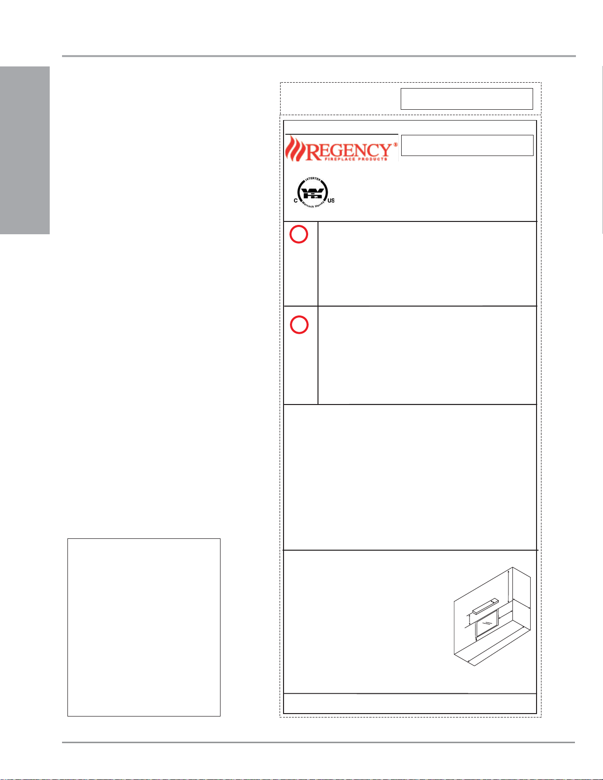
SAFETY LABEL
This is a copy of the label that accompanies
each L676S-NG1 and L676S-LP1 Direct Vent
Gas Fireplace. We have printed a copy of the
contents here for your review.
NOTE: Regency
improved. Check the label on the unit and if
there is a difference, the label on the unit is
the correct one.
INSTALLATION
®
units are constantly being
342
DO NOT REMOVE THIS LABEL / NE PAS ENLEVER CETTE ETIQUETTE
`
342
Serial No. / No de serie
Listed: VENTED GAS FIREPLACE HEATER
Model/Modele:
L676S-NG1
Min. Supply Pressure 5“ WC (1.25 kpa)
Low Setting Man. Pressure 1.6" WC (0.39 kpa)
Max. Manifold Pressure 3.5" WC (0.87 kpa)
Orifice Size #37 DMS
Minimum Input 19,500 Btu/h (5.71 )
Maximum Input 29,000 Btu/h (8.49 kW)
Model/Modele:
L676S-LP1
Min. Supply Pressure 12" WC (2.98 kpa)
Low Setting Man. Pressure 6.4" WC (1.59 kpa)
Max. Manifold Pressure 10" WC (2.49 kpa)
Orifice Size #53 DMS
Minimum Input 21,000 Btu/h (6.15 kW)
Maximum Input 26,000 Btu/h (7.61 kW)
Tested to: ANSI Z21.88a-2007/
CAN/CGA-2.17-M91
Certified for / Certifiée pour: CANADA AND U.S.A.
WN # 16074
NATURAL GAS FIREPLACE: MODEL L676S-NG1
Factory Equipped For Altitude 0-4500ft. (0-1372m)
PROPANE GAS FIREPLACE: MODEL L676S-LP1
Factory Equipped For Altitude 0-4500ft. (0-1372m)
CSA 2.33a-2007,
kW
For the State of Massachusetts, installation
and repair must be done by a plumber or
gasfi tter licensed in the Commonwealth of
Massachusetts.
For the State of Massachusetts, fl exible
connectors shall not exceed 36 inches in
length.
For the State of Massachusetts, the appliances individual manual shut-off must be a
t-handle type valve.
The State of Massachusetts requires the
installation of a carbon monoxide alarm in
accordance with NFPA 720 and a CO alarm
with battery back up in the same room where
the gas appliance is installed.
This appliance must be installed in accordance with the manufacturer’s installation
instructions and with local codes, if any; if none, follow the current ANSI Z223.1 in
For Manufactured Home Installation: This Direct Vent System Appliance must be
installed in accordance with the manufacturer's installation instructions and
COPY OF SAFETY DECAL
Manufactured Home Construction and Safety Standard Title 24 CFR, Part 3280, or the
current Standard for Fire Safety Criteria for Manufactured Home Installation, Sites, and
Communities ANSI/NFPA501A, and with CAN/CSAZ240 MHMobile Home Standard in
Canada.
This appliance is only for use with the type of gas indicated on the rating plate and may
be installed in an aftermarket, permanently located, manufactured (mobile) home
where not prohibited by local codes. See owner's manual for details. This appliance is
not convertible foruse with othergases, unless acertified kit isused (Kit #526-969).
Certified for usewith Heat Wave(Kit #946-556).
For use withglass doors certifiedwith the applianceonly.
Minimum Clearances to Combustibles from Fireplace Opening
Side Walls *A 14-3/4" (375mm)
Ceiling B 52" (813mm)
Min. Mantel Height C 16-1/2" (419mm)
Max. Mantel Depth **D 13” (330mm)
Alcove Width E 84" (2134mm)
Alcove Depth F 36" (914mm)
Finished Floor G 3” (76mm)
Refer to Manual for complete Clearance Details
* Alcove side wall must have a min. of 14-3/4” (375mm) clearance on one side.
** Mantel depth taken at 26-1/2” (673mm) from front facing.
VENTED GAS FIREPLACE HEATER
the USA or the current CAN 1-B149 in Canada.
This vented gas fireplace heater is not for use with air filters.
Electrical Supply: 6.0 VDC
NOT FOR USE WITH SOLID FUEL
C
FPI Fireplace Products International Ltd., Delta BC, CANADA
MADE IN CANADA / FABRIQUE AU CANADA
B
D
G
F
A
E
918-760
44
Regency® L676S Direct Vent Gas Fireplace

REQUIREMENTS
MA Code - CO Detector
(for the State of Massachusetts only)
5.08: Modifications to NFPA-54, Chapter 10
(2) Revise 10.8.3 by adding the following additional requirements:
(a) For all side wall horizontally vented gas fueled equipment installed in every dwelling, building or structure used in whole or in part for
residential purposes, including those owned or operated by the Commonwealth and where the side wall exhaust vent termination is less than
seven (7) feet above finished grade in the area of the venting, including but not limited to decks and porches, the following requirements shall
be satisfied:
1. INSTALLATION OF CARBON MONOXIDE DETECTORS. At the time of installation of the side wall horizontal vented gas fueled
equipment, the installing plumber or gasfitter shall observe that a hard wired carbon monoxide detector with an alarm and battery back-up is
installed on the floor level where the gas equipment is to be installed. In addition, the installing plumber or gasfitter shall observe that a battery
operated or hard wired carbon monoxide detector with an alarm is installed on each additional level of the dwelling, building or structure
served by the side wall horizontal vented gas fueled equipment. It shall be the responsibility of the property owner to secure the services of
qualified licensed professionals for the installation of hard wired carbon monoxide detectors
a. In the event that the side wall horizontally vented gas fueled equipment is installed in a crawl space or an attic, the hard wired carbon
monoxide detector with alarm and battery back-up may be installed on the next adjacent floor level.
b. In the event that the requirements of this subdivision can not be met at the time of completion of installation, the owner shall have a period of
thirty (30) days to comply with the above requirements; provided, however, that during said thirty (30) day period, a battery operated carbon
monoxide detector with an alarm shall be installed.
INSTALLATION
2. APPROVED CARBON MONOXIDE DETECTORS. Each carbon monoxide detector as required in accordance with the above provisions
shall comply with NFPA 720 and be ANSI/UL 2034 listed and IAS certified.
3. SIGNAGE. A metal or plastic identification plate shall be permanently mounted to the exterior of the building at a minimum height of eight
(8) feet above grade directly in line with the exhaust vent terminal for the horizontally vented gas fueled heating appliance or equipment. The
sign shall read, in print size no less than one-half (1/2) inch in size, "GAS VENT DIRECTLY BELOW. KEEP CLEAR OF ALL
OBSTRUCTIONS".
4. INSPECTION. The state or local gas inspector of the side wall horizontally vented gas fueled equipment shall not approve the installation
unless, upon inspection, the inspector observes carbon monoxide detectors and signage installed in accordance with the provisions of 248 CMR
5.08(2)(a)1 through 4.
(b) EXEMPTIONS: The following equipment is exempt from 248 CMR 5.08(2)(a)1 through 4:
1. The equipment listed in Chapter 10 entitled "Equipment Not Required To Be Vented" in the most current edition of NFPA 54 as adopted by
the Board; and
2. Product Approved side wall horizontally vented gas fueled equipment installed in a room or structure separate from the dwelling, building or
structure used in whole or in part for residential purposes.
(c) MANUFACTURER REQUIREMENTS - GAS EQUIPMENT VENTING SYSTEM PROVIDED. When the manufacturer of Product
Approved side wall horizontally vented gas equipment provides a venting system design or venting system components with the equipment, the
instructions provided by the manufacturer for installation of the equipment and the venting system shall include:
1. Detailed instructions for the installation of the venting system design or the venting system components; and
2. A complete parts list for the venting system design or venting system.
(d) MANUFACTURER REQUIREMENTS - GAS EQUIPMENT VENTING SYSTEM NOT PROVIDED. When the manufacturer of a
Product Approved side wall horizontally vented gas fueled equipment does not provide the parts for venting the flue gases, but identifies
"special venting systems", the following requirements shall be satisfied by the manufacturer:
1. The referenced "special venting system" instructions shall be included with the appliance or equipment installation instructions; and
2. The "special venting systems" shall be Product Approved by the Board, and the instructions for that system shall include a parts list and
detailed installation instructions.
(e) A copy of all installation instructions for all Product Approved side wall horizontally vented gas fueled equipment, all venting instructions,
all parts lists for venting instructions, and/or all venting design instructions shall remain with the appliance or equipment at the completion of
the installation.
Regency® L676S Direct Vent Gas Fireplace 55
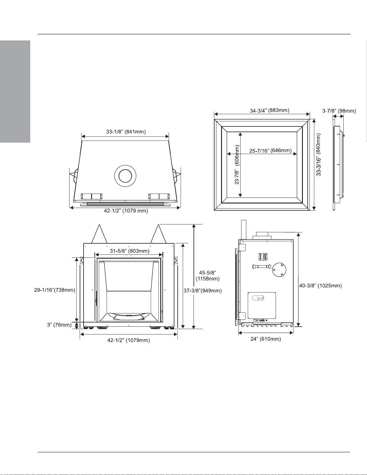
UNIT DIMENSIONS
INSTALLATION
66
Regency® L676S-1 Direct Vent Gas Fireplace
INSTALLATION
IMPORTANT MESSAGE
SAVE THESE
INSTRUCTIONS
The L676S Direct Vent Fireplace must be
installed in accordance with these instructions.
Carefully read all the instructions in this manual
fi rst. Consult the "authority having jurisdiction"
to determine the need for a permit prior to
starting the installation. It is the responsibility of
the installer to ensure this fi replace is installed
in compliance with manufacturers instructions
and all applicable codes.
BEFORE YOU START
Safe installation and operation of this appliance
requires common sense, however, we are
required by the Canadian Safety Standards
and ANSI Standards to make you aware of
the following:
INSTALLATION AND REPAIR SHOULD
BE DONE BY AN AUTHORIZED
SERVICE PERSON. THE APPLIANCE
SHOULD BE INSPECTED BEFORE
USE AND AT LEAST ANNUALLY BY A
PROFESSIONAL SERVICE PERSON.
MORE FREQUENT CLEANING MAY
BE REQUIRED DUE TO EXCESSIVE
LINT FROM CARPETING, BEDDING
MATERIAL, ETC. IT IS IMPERATIVE
THAT CONTROL COMPARTMENTS,
BURNERS AND CIRCULATING AIR
PASSAGEWAYS OF THE APPLIANCE
BE KEPT CLEAN.
DUE TO HIGH TEMPERATURES, THE
APPLIANCE SHOULD BE LOCATED
OUT OF TRAFFIC AND AWAY FROM
FURNITURE AND DRAPERIES.
WARNING: FAILURE TO INSTALL THIS
APPLIANCE CORRECTLY WILL VOID
YOUR WARRANTY AND MAY CAUSE
A SERIOUS HOUSE FIRE.
CHILDREN AND ADULTS SHOULD BE
ALERTED TO THE HAZARDS OF HIGH
SURFACE TEMPERATURES, ESPECIALLY THE FIREPLACE GLASS, AND
SHOULD STAY AWAY TO AVOID BURNS
OR CLOTHING IGNITION.
YOUNG CHILDREN SHOULD BE
CAREFULLY SUPERVISED WHEN
THEY ARE IN THE SAME ROOM AS
THE APPLIANCE.
CLOTHING OR OTHER FLAMMABLE
MATERIAL SHOULD NOT BE PLACED
ON OR NEAR THE APPLIANCE.
GENERAL SAFETY
INFORMATION
1) The appliance installation must conform
with local codes or, in the absence of local
codes, with the current Canadian or National
Gas Codes, CAN1-B149 or ANSI Z223.1
Installation Codes.
2) The appliance when installed, must be electrically grounded in accordance with local
codes, or in the absence of local codes with
the current National Electrical Code, ANSI/
NFPA 70 or CSA C22.1 Canadian Electrical
Code.
3) See general construction and assembly
instructions. The appliance and vent should
be enclosed.
4) This appliance must be connected to the
specifi ed vent and termination cap to the
outside of the building envelope. Never vent
to another room or inside a building. Make
sure that the vent is fi tted as per Venting
instructions.
5) Inspect the venting system annually for
blockage and any signs of deterioration.
6) Venting terminals shall not be recessed into
a wall or siding.
7) Any safety glass removed for servicing
must be replaced prior to operating the
appliance.
8) To prevent injury, do not allow anyone who
is unfamiliar with the operation to use the
fi replace.
9) Wear gloves and safety glasses for protection
while doing required maintenance.
10) Be aware of electrical wiring locations in
walls and ceilings when cutting holes for
termination.
11) Under no circumstances should this
appliance be modifi ed. Parts that have to
be removed for servicing should be replaced
prior to operating this appliance.
12) Installation and any repairs to this appliance
should be done by an authorized service
person. A professional service person should
be called to inspect this appliance annually.
Make it a practice to have all of your gas
appliances checked annually.
13) Do not slam shut or strike the glass door.
14) Under no circumstances should any solid
fuels (wood, paper, cardboard, coal, etc.)
be used in this appliance.
15) The appliance area must be kept clear and
free of combustible materials, (gases and
other fl ammable vapours and liquids).
Emissions from burning wood or gas could
contain chemicals known to the State of
California to cause cancer, birth defects or
other reproductive harm.
INSTALLATION
CHECKLIST
1) Locate appliance
a) Room location (Refer to "Locating Your
Gas fi replace" section)
b) Clearances to Combustibles (Refer to
"Clearances" section)
c) Mantle Clearances (Refer to "Mantel
Clearances" section)
d) Framing & Finishing Requirements
(Refer to "Framing & Finishing"
section)
e) Venting Requirements (Refer to
"Venting" section)
2) Assemble Top and Side Standoffs (Refer to
"Unit Assembly Prior to Installation).
3) Install batteries; four "AA" batteries in the
wall mounted receiver; three "AAA" batteries
in the remote control and one "AA" battery
into the DC Sparker(p.36). (Refer to remote
control manual for operating instructions).
4) Convert to propane if desired (Refer to
"Conversion from NG to LP" section).
5) Slide unit into place.
6) Install vent (Refer to "Venting Arrangement"
sections).
7) Make gas connections (Refer to "Gas Line
Installation section).
8) Test the pilot (Refer to "Pilot Adjustment"
section).
INSTALLATION
Regency® L676S Direct Vent Gas Fireplace 7
INSTALLATION
9) Test Gas Pressure (Refer to "Gas Pipe Pres-
sure Testing" section).
10) Install standard and optional features. Refer
to the following sections:
a) Inside Panels
b) Glass Crystals or Ceramic Stones
c) Remote Control - refer to "Matching
Remote Handset & Control Box
ID Code" section.
d) Outer Faceplate
INSTALLATION
11) Final check.
Before leaving this unit with the customer, the
installer must ensure that the appliance is fi ring
correctly and operation fully explained to
customer.
This includes:
1) Clocking the appliance to ensure the correct
fi ring rate (rate noted on label 29,000 (NG)
Btu/h, 26,000 (LP) Btu/h) after burning
appliance for 15 minutes.
2) If required, adjusting the primary air to ensure
that the fl ame does not carbon. First allow
the unit to burn for 15-20 min. to stabilize.
CAUTION: Any alteration to the product that
causes sooting or carboning that results
in damage is not the responsibility of the
manufacturer.
MANUFACTURED
MOBILE HOME
ADDITIONAL
REQUIREMENTS
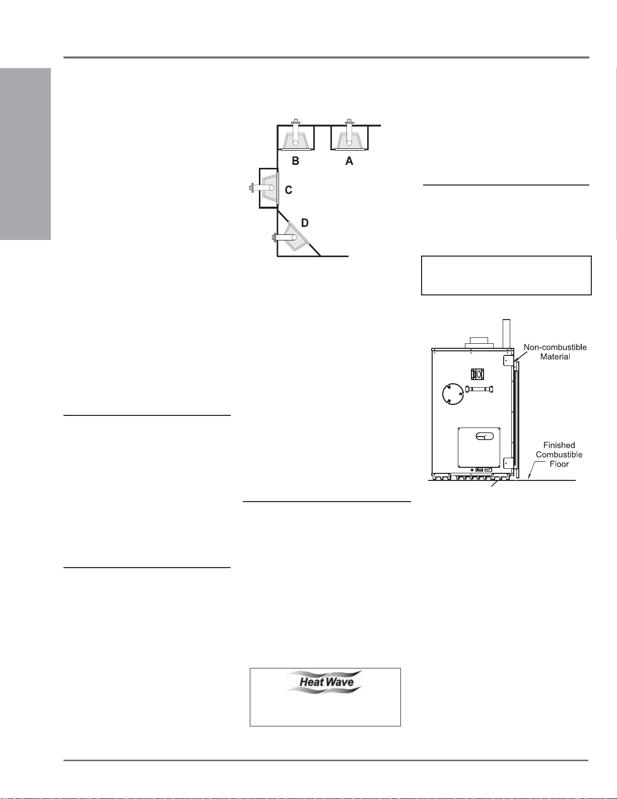
3) The L676S Direct Vent Gas Fireplace can
be installed in a recessed position or framed
out into the room as in A, B, C and D. See
Diagram 1.
A) Flat on Wall
B) Flat on Wall Corner
C) Recessed into
Wall/Alcove
D) Corner
Diagram 1
4) This appliance is Listed for bedroom
installations using the standard Remote
(millivolt thermostat system). Some areas
may have further requirements, check local
codes before installation.
5) The L676S Direct Vent Gas Fireplace
is approved for alcove installations, see
"Clearances" section for details.
6) We recommend that you plan your installation
on paper using exact measurements for
clearances and floor protection before
actually installing this appliance. Have an
authorized inspector, dealer, or installer
review your plans before installation.
Note: For vent terminations refer to
"Exterior Vent Termination Locations"
section.
HEAT RELEASE KIT
The Heat Release Kit expels warm air from the
fi replace to the outside of the building, allowing
the fi replace to be operated with less heat entering
the room. The kit may be used on either the left
or right side.
See Heat Release installation manual for complete
details and clearances from side only.
FINISHED FLOOR
The maximum height that combustible fl oor can
be brought above the base of the unit is 0".
Note: If fi nished fl oor is any higher than the
base of the unit, the facepate will not
fi t into place.
1) Ensure that structural members are not cut
or weakened during installation.
2) Ensure proper grounding using the #8
ground lug provided. See "Wiring Diagram"
section.
LOCATING YOUR
GAS FIREPLACE
1) When selecting a location for your fi replace,
ensure that the clearances are met.
2) The appliance must be installed on a fl at,
solid, continuous surface (e.g. wood, metal,
concrete). This may be the fl oor, or raised up
on a platform to enhance its visual impact.
The appliance must be installed on a metal
or wood panel extending the full width and
depth of the appliance.
8
HEATWAVE
DUCT KIT
The HeatWave Air Duct Kit increases the
effectiveness of your fi replace by dispersing
warm air from the fi replace to remote locations
in the same room or other rooms in your home.
Up to two kits may be installed on the fi replace.
Please Note: Only 1 HeatWave kit may be
operated at one time.
See HeatWave installation manual for complete
details and clearances from side only.
The HeatWave Duct Kit has different
clearance and framing requirements,
check the HeatWave manual for details.
Regency® L676S Direct Vent Gas Fireplace
CLEARANCES
INSTALLATION
The clearances listed below are Minimum distances unless otherwise stated:
A major cause of chimney related fi res is failure to maintain required clearances (air space) to combustible materials. It is of the greatest
importance that this fi replace and vent system be installed only in accordance with these instructions.
The top, back and sides of the fi replace are defi ned by
standoffs. The metal ends of the standoff may NOT be
Caution Requirements
recessed into combustible construction.
Clearance to Combustibles from:
Back 0" (0mm)
Side 0" (0mm)
Floor 0" (0mm)
to ceiling
52” (1321mm)
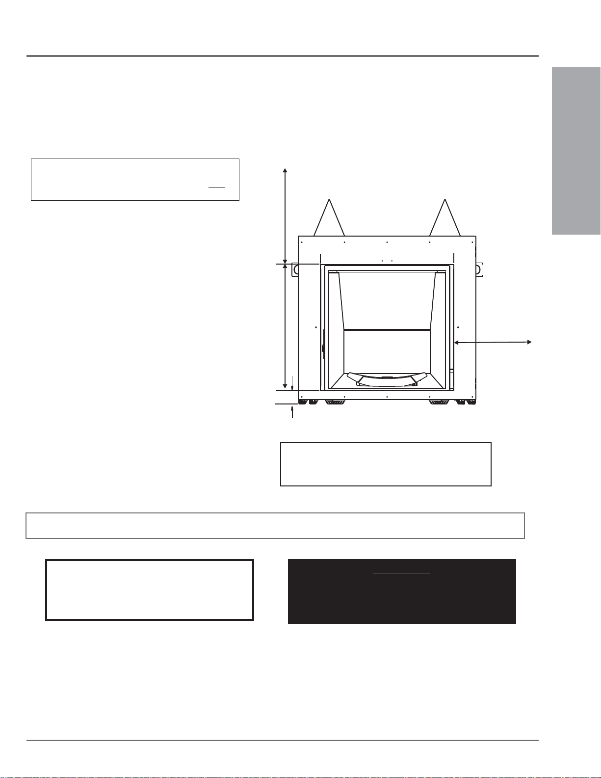
“NON-COMBUSTIBLE FACING”
Minimum Clearance from Top of Front Facing:
Mantel min. 16-1/2" (419mm)
Ceiling 52" (813mm) from top of front facing
Side Wall to Unit:
14-3/4"* (375mm)
Horizontal Vent Clearances to Combustibles:
Top 3" (76mm)
Side 2" (51mm)
Bottom 2" (51 mm)
28-1/16” (713mm)
14-3/4”
(375mm)
INSTALLATION
Vertical Vent Clearances to Combustibles:
All Sides 2" (51mm)
Alcove Clearances:
Min. Depth 36" (914mm)
Min. Width* 84" (2134mm)
Min. Height 84" (2032mm)
* Alcove side wall must have a minimum of 14-3/4" (375mm) clearance on one side.
3”
(76mm)
NOTE: Only materials such as, but not limited to durarock,
wonderboard and concrete board may be put on the front face
of this appliance. See specifi c requirements under "Framing
and Finishing" section.
IMPORTANT: One set of inner panels must be installed (see P 32). The operation of this unit without inner panels is prohibited.
Fire hazard is an extreme risk
WARNING
if these clearances (air space) to combustible materials
are not adhered to. It is of greatest importance that this
fi replace and vent system be installed only in
accordance with these instructions.
If converting this unit to LP, it is highly recommened
the conversion be done BEFORE the unit is slid into
position for ease of conversion. See "Conversion
from NG to LP" section for instructions.
IMPORTANT
Regency® L676S Direct Vent Gas Fireplace 9
INSTALLATION
4"
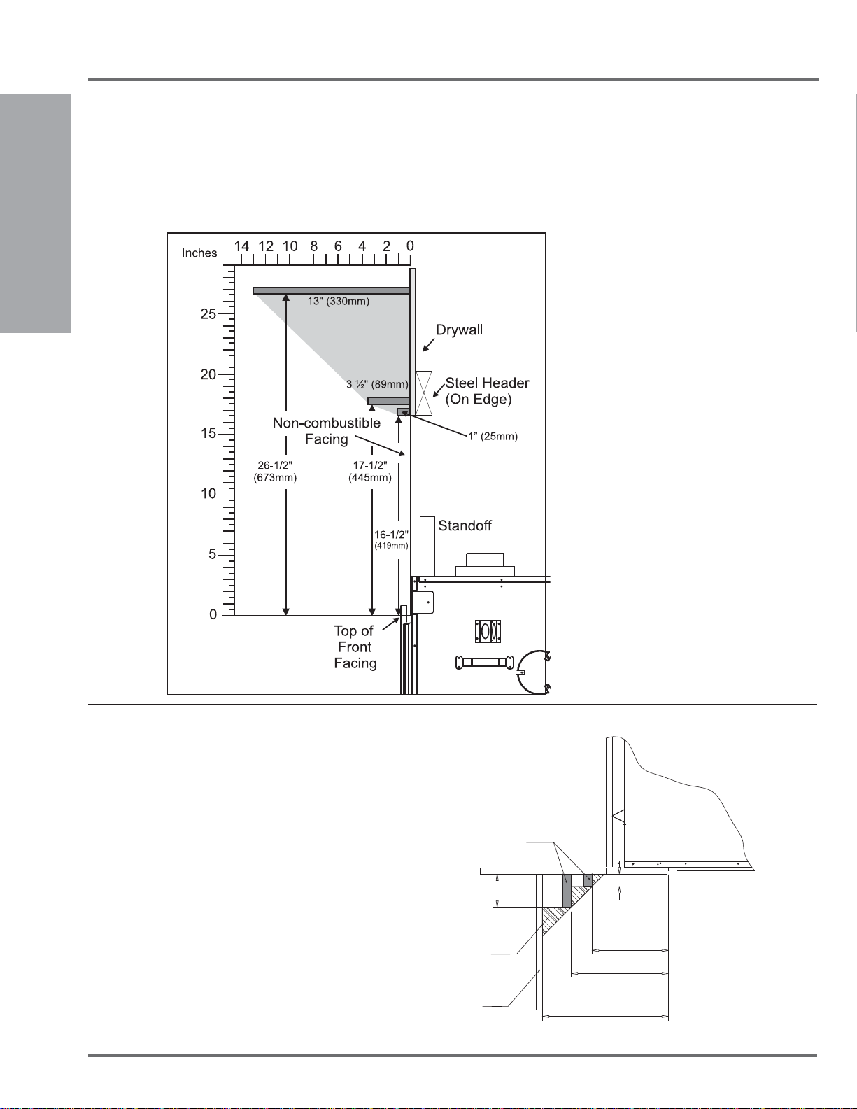
MANTEL CLEARANCES
Because of the extreme heat this fi replace emits, the mantel clearances are critical. Combustible mantel clearances from top of front facing
are shown in the diagram below.
Note: A non-combustible mantel may be installed at a lower height if the framing is made of metal studs covered with a non-combustible
board.
INSTALLATION
Note: Ensure the paint that is used
on the mantel and the facing is
"heat resistant" or the paint may
discolour.
Combustible mantel leg clearances as per diagram:
10
MANTEL LEG CLEARANCES
MANTEL LEG
Allowable mantel
leg projection
Side wall
L676S UNIT
1.5"
9” (229mm)
11” (279mm)
14-3/4” (375mm)
Regency® L676S Direct Vent Gas Fireplace
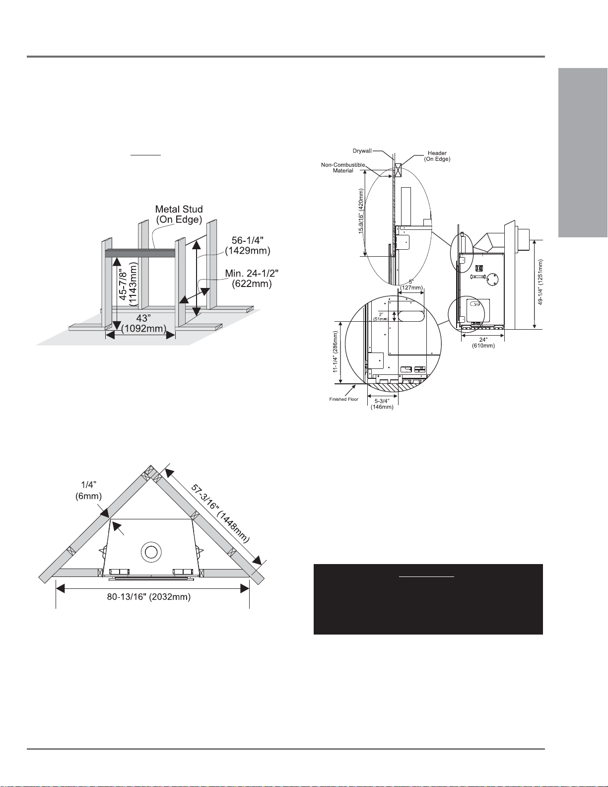
FRAMING
INSTALLATION
1) Frame in the enclosure for the unit with framing material. The framed
opening for the assembled kit is 45-7/8" high x 43" wide x 24-1/2"
deep (1143mm x H 1092mm W x 622mm D). See Diagram 1. Also
see Diagram 2 for corner installations.
IMPORTANT: Header must be metal stud. All other framing may
be of combustible type such as 2x4 / 2x6 framing materials.
Diagram 1
Framing
Note: The 24-1/2" fl ush framing depth (and the corner
framing installation) are based upon 1/2" drywall around
the perimeter of the fi replace on all three sides.
Note: When constructing the framed opening, please ensure
there is access to install the gas lines when the unit is
installed. See Diagram 3 for details.
Diagram 3
2) For exterior walls, insulate the enclosure to the same degree
as the rest of the house, apply vapour barrier and drywall, as
per local installation codes. (Do not insulate the fi replace
itself.)
INSTALLATION
3) The unit does not have to be completely enclosed in a chase.
You must maintain clearances from the vent to combustible
materials: See "Clearances" section. Combustible materials
can be laid against the side and back standoffs and the stove
base.
IMPORTANT
If converting this unit to LP, it is highly recommened the
conversion be done BEFORE the unit is slid into position
for ease of conversion. See "Conversion from NG to LP"
Diagram 2
Regency® L676S Direct Vent Gas Fireplace 11
section for instructions.
INSTALLATION
47-5/8"
(1209mm)
6-7/16"
(163mm)
3"
(76mm)
32-1/16”
(814mm)
15-9/16"
(392mm)
29-1/16”
(738mm)
31-5/8"
(803mm)
44-1/2"
(1130mm)
Non-combustible
Material
Non-combustible Material
Non-combustible
Material
Non-combustible
Material
Metal
Stud
Finished Floor
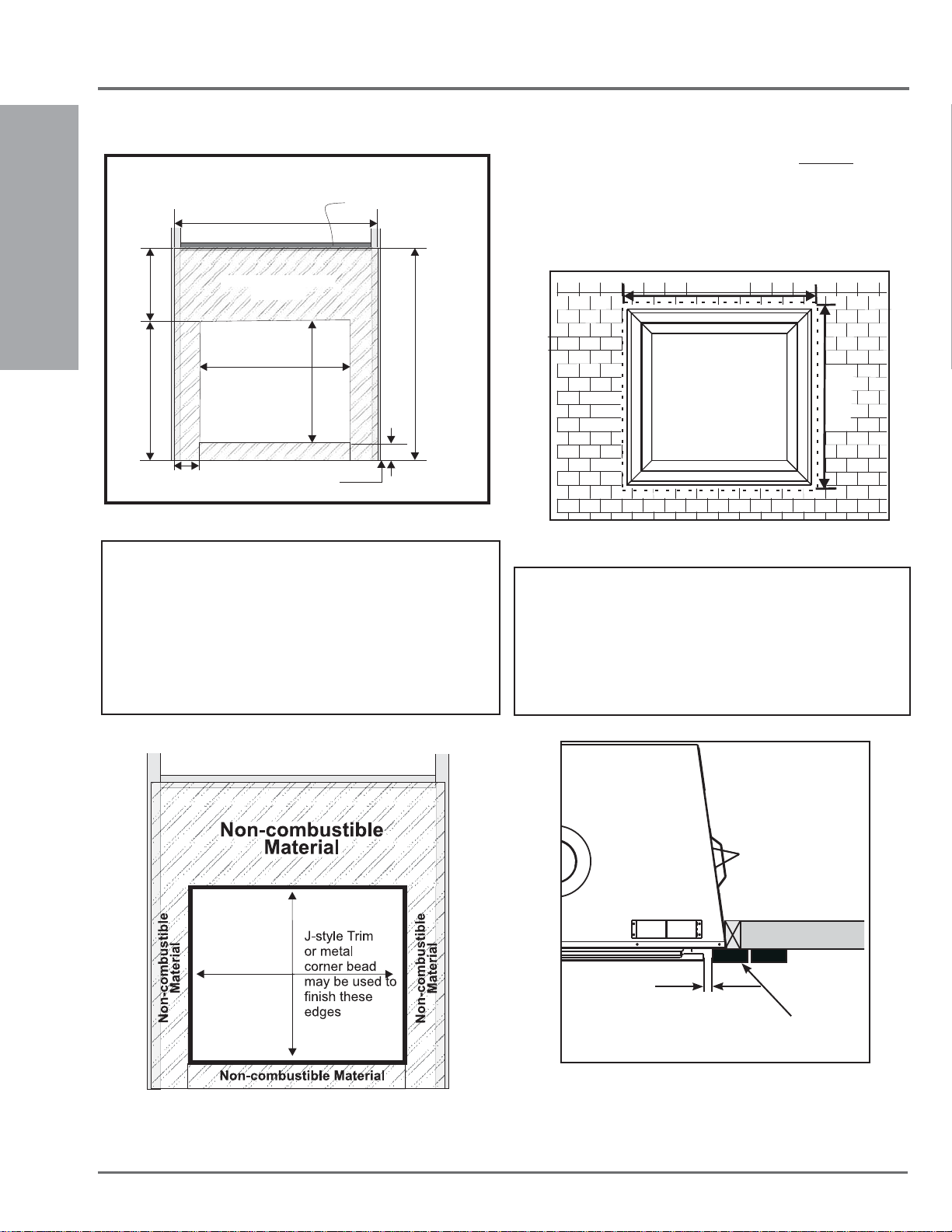
NON-COMBUSTIBLE REQUIREMENTS
FINISHING
1) Finishing material such as tile, river rock, etc. must not protrude
beyond the front facing fl anges on all 4 sides of the fi rebox opening.
2) If material such as brick, stone, etc. extends past the faceplate depth,
when fi nishing around the faceplate, the minimum opening dimension
noted below (Diagram 3) must be adhered to - to ensure the faceplate
can be removed.
INSTALLATION
Diagram 1
Note: All non-combustible facing material should butt up cleanly to
the fl anges around the fi rebox opening.
Rough edges may be visible, from an angle, through the 1/2" gap
behind the faceplate.
To obtain a clean edge, facing material edges may be fi nished
with a J-style trim or metal cornerbead (both materials available
at your local building or hardware outlet) see diagram 2.
Important: Materials used must be NON-COMBUSTIBLE
36 -1/4”
34 -9/16”
Diagram 3
Important:
A 3/4" gap must be maintained all around the outer edge of
the faceplate and the edge of any fi nishing material thicker than
1-1/4" (see diagram 4).
This gap is required to facilitate the installation of the faceplate and
to ensure the removal of the faceplate for service access.
12
Diagram 2
3/4"
Finishing Material
(thickness + 1-1/4")
Diagram 4
Regency® L676S Direct Vent Gas Fireplace
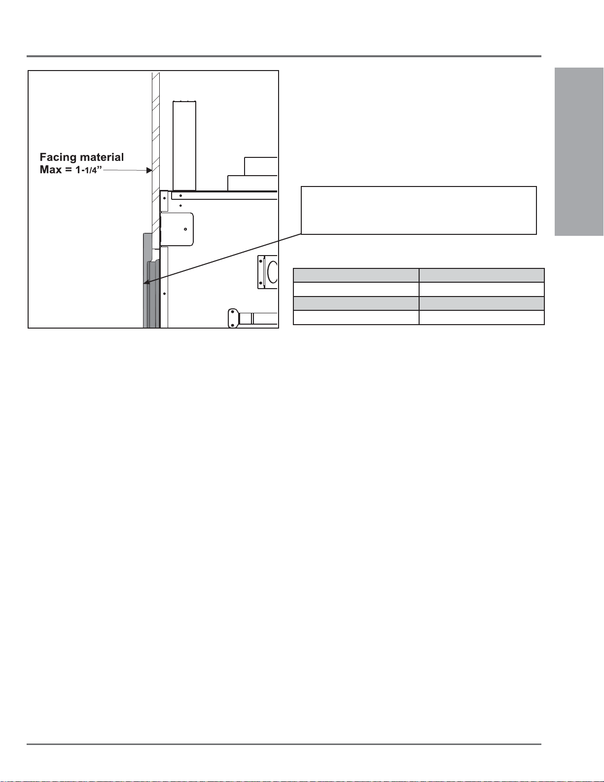
INSTALLATION
To accommodate various thicknesses of facing material - the
faceplate is adjustable to a maximum of 1-1/4" and a minimum
of 1/2" .
See chart below and page 35 for detailed instructions.
Finished Facing Thickness Faceplate Adjustment
1/2" Factory Setting
1/2" - 7/8" (or less) Adjusted to + 3/8"
7/8" - 1-1/4" (or less) Adjusted to + 3/4"
INSTALLATION
Diagram 5
Regency® L676S Direct Vent Gas Fireplace 13
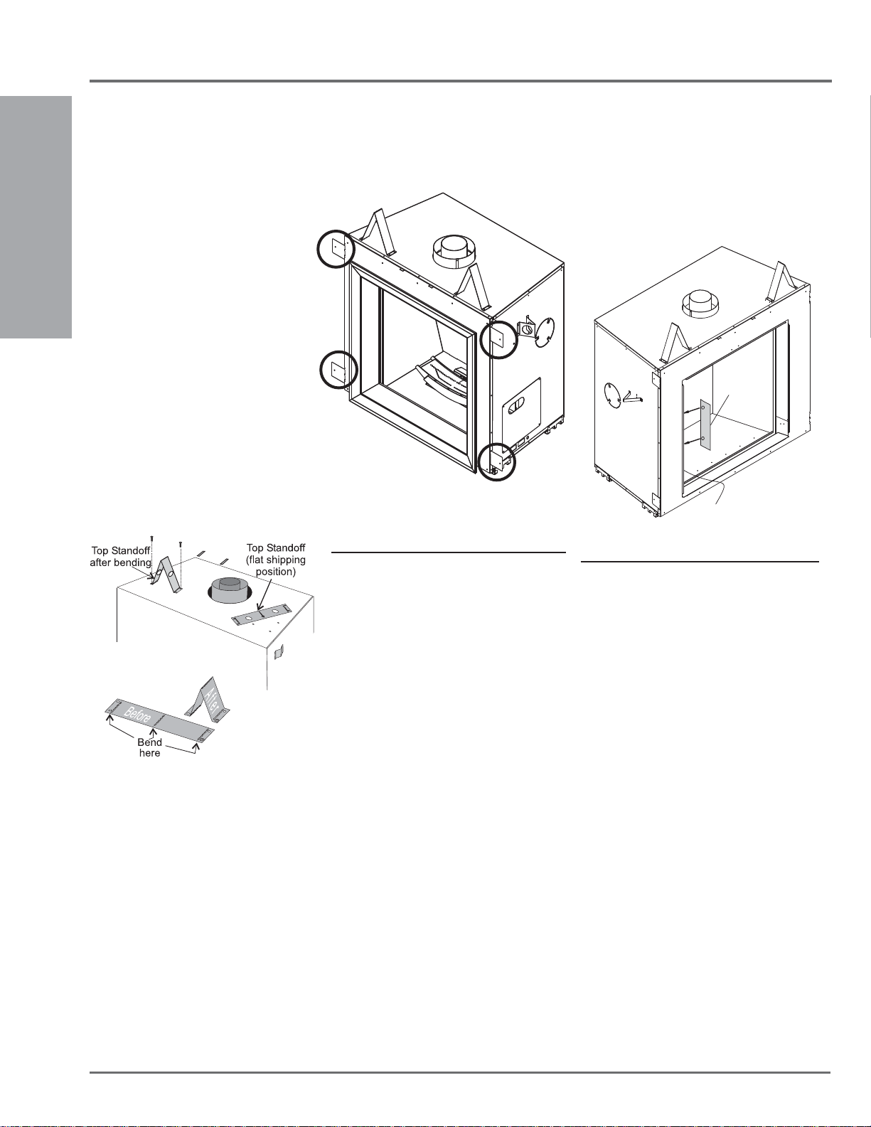
INSTALLATION
UNIT ASSEMBLY
PRIOR TO
INSTALLATION
The Top Facing Support, the Side Nailing Str ips
and the 2 Top Standoffs must be correctly
positioned and attached to the top before unit
is slipped into position.
INSTALLATION
TOP STANDOFF ASSEMBLY
The top standoffs are shipped in a fl at position
and must be folded into shape and attached.
1) Remove the standoffs from the fi replace
top.
2) Take each standoff and bend into the correct
shape. Bend up at the bend lines until the
screw holes in the standoff and the prepunched screw holes on the fi replace top
line up.
3) Attach the standoff securely to the top
with 2 screws per standoff (on opposite
corners).
SIDE NAILING STRIPS
The side nailing strips come attached to the unit.
There are 2 plates on each side, one on the top
and bottom that can be folded out as required.
Side Nailing Strips shown folded out.
The Finishing Template uses two magnets to
attach itself to the fl ange on the left or right side
of the unit (see diagram below). Install the facing
material up to the outside edge (when facing the
unit) of the fi nishing template. This template
may be discarded after the facing material has
been installed.
Finishing
Template
Left Side Flange
FINISHING TEMPLATE
In order to maintain a clean face; the L676S
allows for a 1/8” in overlap of fi nishing material,
such as rock or tile, on both the left and right
hand sides of the unit (top and bottom sides do
not allow for an overlap), this overlap must not
be exceeded or the glass door will no longer
open properly.
Non-combustible wall board is installed up to the
fl anges on all sides of the unit. When installing
any additional facing material use the Finishing
Template (included with the unit) to ensure
that the fi nishing material does not exceed the
allowable overlap.
VENTING
INTRODUCTION
The L676S uses the "balanced fl ue" technology
Co Axial system. The inner liner vents products
of combustion to the outside while the outer liner
draws outside combustion air into the combustion
chamber thereby eliminating the need to use
heated room air for combustion and losing warm
room air up the chimney.
Note: These fl ue pipes must not be connected
to any other appliance.
The gas appliance and vent system must be
vented directly to the outside of the building,
and never be attached to a chimney serving a
separate solid fuel or gas burning appliance.
Each direct vent gas appliance must use it's own
separate vent system. Common vent systems
are prohibited.
14
Regency® L676S Direct Vent Gas Fireplace
 Loading...