


THE TEMPERATURE
CONTROLLER
MODEL TCU INSTRUCTION MANUAL
INTRODUCTION
The Temperature Control Unit (TCU) is a multi-purpose series of industrial control products that are field-programmable for solving various applications. This series of products is built around the concept that the end user has the capability to program different personalities and functions into the unit in order to adapt to different indication and control requirements.
The TCU unit, which you have purchased, has the same high quality workmanship and advanced technological capabilities that have made Red Lion Controls the leader in today’s industrial market.
Red Lion Controls has a complete line of industrial indication and control equipment, and we look forward to servicing you now and in the future.
C UR L US LISTED
IND. CONT. EQ.
51EB
CAUTION: Read complete instructions prior to installation
and operation of the unit.
CAUTION: Risk of electric shock.
Table of Contents
GENERAL DESCRIPTION · · · · · · · · · · · · · · · · · · · · · · · · · · · · · · · · · · · · · · · · · · · · · · · · · · · · · · · 1
SAFETY SUMMARY · · · · · · · · · · · · · · · · · · · · · · · · · · · · · · · · · · · · · · · · · · · · · · · · · · · · · · · · · 2
INSTALLATION & CONNECTIONS · · · · · · · · · · · · · · · · · · · · · · · · · · · · · · · · · · · · · · · · · · · · · · · · · 3
Installation Environment · · · · · · · · · · · · · · · · · · · · · · · · · · · · · · · · · · · · · · · · · · · · · · · · · · · · · · · 3 Standard Unit Installation · · · · · · · · · · · · · · · · · · · · · · · · · · · · · · · · · · · · · · · · · · · · · · · · · · · · · · 3 NEMA 4X/IP65 Unit Installation · · · · · · · · · · · · · · · · · · · · · · · · · · · · · · · · · · · · · · · · · · · · · · · · · 3 Unit Removal Procedure · · · · · · · · · · · · · · · · · · · · · · · · · · · · · · · · · · · · · · · · · · · · · · · · · · · · · · 5 Removing Bezel Assembly · · · · · · · · · · · · · · · · · · · · · · · · · · · · · · · · · · · · · · · · · · · · · · · · · · · · 5 Installing Bezel Assembly · · · · · · · · · · · · · · · · · · · · · · · · · · · · · · · · · · · · · · · · · · · · · · · · · · · · · · 5 Output Modules · · · · · · · · · · · · · · · · · · · · · · · · · · · · · · · · · · · · · · · · · · · · · · · · · · · · · · · · · · · · · 6
Output Module Restrictions · · · · · · · · · · · · · · · · · · · · · · · · · · · · · · · · · · · · · · · · · · · · · · · · · · 6 Installing Output Modules · · · · · · · · · · · · · · · · · · · · · · · · · · · · · · · · · · · · · · · · · · · · · · · · · · · 6
Typical Connections · · · · · · · · · · · · · · · · · · · · · · · · · · · · · · · · · · · · · · · · · · · · · · · · · · · · · · · |
6 |
Select Input Sensor Type · · · · · · · · · · · · · · · · · · · · · · · · · · · · · · · · · · · · · · · · · · · · · · · · · · · · · |
7 |
Select AC Power (115/230 VAC) |
· · · · · · · · · · · · · · · · · · · · · · · · · · · · · · · · · · · · · · · · · · · · · · · · 7 |
|||
EMC INSTALLATION GUIDELINES · · · · · · · · · · · · · · · · · · · · · · · · · · · · · · · · · · · · · · · · · · · · · · 8 |
||||
Wiring Connections |
· · · · · · · · · · · · · · · · · · · · · · · · · · · · · · · · · · · · · · · · · · · · · · · · · · · · · · · · · · 8 |
|||
Signal Wiring · · · · · · · · · · · · · · · · · · · · · · · · · · · · · · · · · · · · · · · · · · · · · · · · · · · · · · · · · · · · 9 |
||||
Valve Positioner Wiring |
· · · · · · · · · · · · · · · · · · · · · · · · · · · · · · · · · · · · · · · · · · · · · · · · · · · 10 |
|||
Linear DC Output Wiring |
· · · · · · · · · · · · · · · · · · · · · · · · · · · · · · · · · · · · · · · · · · · · · · · · · · · 10 |
|||
Second Analog Input Wiring · · · · · · · · · · · · · · · · · · · · · · · · · · · · · · · · · · · · · · · · · · · · · · · · 10 |
||||
Heater Current Monitor Wiring |
· · · · · · · · · · · · · · · · · · · · · · · · · · · · · · · · · · · · · · · · · · · · · · 11 |
|||
Program Disable Or User Input Wiring · · · · · · · · · · · · · · · · · · · · · · · · · · · · · · · · · · · · · · · · · 11 |
||||
AC Power Wiring |
· · · · · · · · · · · · · · · · · · · · · · · · · · · · · · · · · · · · · · · · · · · · · · · · · · · · · · · · 11 |
|||
FRONT PANEL DESCRIPTION |
· · · · · · · · · · · · · · · · · · · · · · · · · · · · · · · · · · · · · · · · · · · · · · · · · · 12 |
|||
Button Functions · · · · · · · · · · · · · · · · · · · · · · · · · · · · · · · · · · · · · · · · · · · · · · · · · · · · · · · · · · · 12 |
||||
OPERATION OVERVIEW · · · · · · · · · · · · · · · · · · · · · · · · · · · · · · · · · · · · · · · · · · · · · · · · · · · · · · · 13 |
||||
Controller Power-up |
· · · · · · · · · · · · · · · · · · · · · · · · · · · · · · · · · · · · · · · · · · · · · · · · · · · · · · · · · 13 |
|||
Controller Power Down · · · · · · · · · · · · · · · · · · · · · · · · · · · · · · · · · · · · · · · · · · · · · · · · · · · · · · · 13 |
||||
Process Start-up · · · · · · · · · · · · · · · · · · · · · · · · · · · · · · · · · · · · · · · · · · · · · · · · · · · · · · · · · · · 13 |
||||
Manual (User) & Automatic Operation |
· · · · · · · · · · · · · · · · · · · · · · · · · · · · · · · · · · · · · · · · · · 13 |
|||
Remote And Local Setpoint Operation |
· · · · · · · · · · · · · · · · · · · · · · · · · · · · · · · · · · · · · · · · · · · 14 |
|||
i
Configuration Of Parameters · · · · · · · · · · · · · · · · · · · · · · · · · · · · · · · · · · · · · · · · · · · · · · · · · · 15 Parameter Entry · · · · · · · · · · · · · · · · · · · · · · · · · · · · · · · · · · · · · · · · · · · · · · · · · · · · · · · · · · · · 16 Normal Display Mode · · · · · · · · · · · · · · · · · · · · · · · · · · · · · · · · · · · · · · · · · · · · · · · · · · · · · · · · 16 Modifying A Secondary Display Parameter From The Front Panel · · · · · · · · · · · · · · · · · · · · · · · 16
UNPROTECTED PARAMETER MODE · · · · · · · · · · · · · · · · · · · · · · · · · · · · · · · · · · · · · · · · · · · · · 17
Unprotected Parameter Mode Reference Table · · · · · · · · · · · · · · · · · · · · · · · · · · · · · · · · · · · · 17 Protected Parameter Mode Reference Table · · · · · · · · · · · · · · · · · · · · · · · · · · · · · · · · · · · · · · 19
PROTECTED PARAMETER MODE · · · · · · · · · · · · · · · · · · · · · · · · · · · · · · · · · · · · · · · · · · · · · · · · 19 Front Panel Program Disable · · · · · · · · · · · · · · · · · · · · · · · · · · · · · · · · · · · · · · · · · · · · · · · · · · · 20
Models With User Input |
· · · · · · · · · · · · · · · · · · · · · · · · · · · · · · · · · · · · · · · · · · · · · · · · · · · · · · 20 |
||
Models With Program Disable |
· · · · · · · · · · · · · · · · · · · · · · · · · · · · · · · · · · · · · · · · · · · · · · · · · 20 |
||
HIDDEN FUNCTION MODE |
· · · · · · · · · · · · · · · · · · · · · · · · · · · · · · · · · · · · · · · · · · · · · · · · · · · · · 21 |
||
Hidden Function Mode Reference Table · · · · · · · · · · · · · · · · · · · · · · · · · · · · · · · · · · · · · · · · · · 21 |
|||
CONFIGURATION PARAMETER MODULES · · · · · · · · · · · · · · · · · · · · · · · · · · · · · · · · · · · · · · · · 22 |
|||
Input Module (1- In) |
· · · · · · · · · · · · · · · · · · · · · · · · · · · · · · · · · · · · · · · · · · · · · · · · · · · · · · · · · 22 |
||
Input Type (type) |
· · · · · · · · · · · · · · · · · · · · · · · · · · · · · · · · · · · · · · · · · · · · · · · · · · · · · · · · 22 |
||
Temperature Scale (SCAL) |
· · · · · · · · · · · · · · · · · · · · · · · · · · · · · · · · · · · · · · · · · · · · · · · · · 22 |
||
Temperature Resolution (dCPt) · · · · · · · · · · · · · · · · · · · · · · · · · · · · · · · · · · · · · · · · · · · · · · 22 Input Signal Filter and Display Update Rate (FLtr) · · · · · · · · · · · · · · · · · · · · · · · · · · · · · · · · 22 Input Sensor Correction Constants (SPAN & SHFt) · · · · · · · · · · · · · · · · · · · · · · · · · · · · · · · 23 Setpoint Limit Values (SPLO & SPHI) · · · · · · · · · · · · · · · · · · · · · · · · · · · · · · · · · · · · · · · · · 23 Setpoint Ramp Rate (SPrP) · · · · · · · · · · · · · · · · · · · · · · · · · · · · · · · · · · · · · · · · · · · · · · · · 23 User Input · · · · · · · · · · · · · · · · · · · · · · · · · · · · · · · · · · · · · · · · · · · · · · · · · · · · · · · · · · · · · · 24 Heater Current Monitor Scaling (HCur) (Optional) · · · · · · · · · · · · · · · · · · · · · · · · · · · · · · · · 24
Output Module (2-OP) · · · · · · · · · · · · · · · · · · · · · · · · · · · · · · · · · · · · · · · · · · · · · · · · · · · · · · · 25 Time Proportioning Cycle Time (CYCt) · · · · · · · · · · · · · · · · · · · · · · · · · · · · · · · · · · · · · · · · 25 Output Control Action (OPAC) · · · · · · · · · · · · · · · · · · · · · · · · · · · · · · · · · · · · · · · · · · · · · · · 25 Output Power Limits (OPLO & OPHI) · · · · · · · · · · · · · · · · · · · · · · · · · · · · · · · · · · · · · · · · · 25 Sensor Fail Preset Power (OPFL) · · · · · · · · · · · · · · · · · · · · · · · · · · · · · · · · · · · · · · · · · · · · 25 Output Power Dampening (OPdP) · · · · · · · · · · · · · · · · · · · · · · · · · · · · · · · · · · · · · · · · · · · · 26 ON/OFF Control Hysteresis Band (CHYS) · · · · · · · · · · · · · · · · · · · · · · · · · · · · · · · · · · · · · · 26 Auto-Tune Dampening Code (tcod) · · · · · · · · · · · · · · · · · · · · · · · · · · · · · · · · · · · · · · · · · · · 26 Linear DC Analog Output (ANAS, ANLO, ANHI, ANdb, ANUt) (Optional) · · · · · · · · · · · · · · · 27
Lockouts Module (3-LC) · · · · · · · · · · · · · · · · · · · · · · · · · · · · · · · · · · · · · · · · · · · · · · · · · · · · · · 28
ii
Lower Display Lockouts (SP, OP, HCur, IN-2, dEv, UdSP) · · · · · · · · · · · · · · · · · · · · · · · · · 28 Protected Mode Lockouts (Code, PID, PID2, rtbS & AL) · · · · · · · · · · · · · · · · · · · · · · · · · · · 28 Hidden Mode Lockouts (ALrS, trnF, tUNE and SPSL) · · · · · · · · · · · · · · · · · · · · · · · · · · · · · 28
Alarm Module (4-AL) (Optional) |
· · · · · · · · · · · · · · · · · · · · · · · · · · · · · · · · · · · · · · · · · · · · · · · · 29 |
||
Alarm Action (Act1, Act2) |
· · · · · · · · · · · · · · · · · · · · · · · · · · · · · · · · · · · · · · · · · · · · · · · · · · 29 |
||
Second Analog Input Alarm · · · · · · · · · · · · · · · · · · · · · · · · · · · · · · · · · · · · · · · · · · · · · · · · · 29 |
|||
Heater Break Alarm (HcUr) |
· · · · · · · · · · · · · · · · · · · · · · · · · · · · · · · · · · · · · · · · · · · · · · · · · 29 |
||
Valve Fail Alarm (VFAL) |
· · · · · · · · · · · · · · · · · · · · · · · · · · · · · · · · · · · · · · · · · · · · · · · · · · · 29 |
||
Alarm Reset (rSt1, rSt2) |
· · · · · · · · · · · · · · · · · · · · · · · · · · · · · · · · · · · · · · · · · · · · · · · · · · · 33 |
||
Alarm Standby Delay (Stb1, Stb2) · · · · · · · · · · · · · · · · · · · · · · · · · · · · · · · · · · · · · · · · · · · · 33 |
|||
Alarm Value (AL-1, AL-2) |
· · · · · · · · · · · · · · · · · · · · · · · · · · · · · · · · · · · · · · · · · · · · · · · · · · 33 |
||
Alarm Hysteresis (AHYS) |
· · · · · · · · · · · · · · · · · · · · · · · · · · · · · · · · · · · · · · · · · · · · · · · · · · 34 |
||
Cooling Output Module (5-02) (Optional) |
· · · · · · · · · · · · · · · · · · · · · · · · · · · · · · · · · · · · · · · · · 34 |
||
Cooling Cycle Time (CYC2) |
· · · · · · · · · · · · · · · · · · · · · · · · · · · · · · · · · · · · · · · · · · · · · · · · 34 |
||
Cooling Relative Gain (GAN2) · · · · · · · · · · · · · · · · · · · · · · · · · · · · · · · · · · · · · · · · · · · · · · · 34 |
|||
Heat-Cool Overlap/Deadband (db-2) |
· · · · · · · · · · · · · · · · · · · · · · · · · · · · · · · · · · · · · · · · · · 34 |
||
Serial Communications Module (6-SC) (Optional) · · · · · · · · · · · · · · · · · · · · · · · · · · · · · · · · · · · 35 Baud Rate (bAUd) · · · · · · · · · · · · · · · · · · · · · · · · · · · · · · · · · · · · · · · · · · · · · · · · · · · · · · · · 35 Parity Bit (PArb) · · · · · · · · · · · · · · · · · · · · · · · · · · · · · · · · · · · · · · · · · · · · · · · · · · · · · · · · · 35 Address Number (Addr) · · · · · · · · · · · · · · · · · · · · · · · · · · · · · · · · · · · · · · · · · · · · · · · · · · · 35 Abbreviated or Full Transmission (Abrv) · · · · · · · · · · · · · · · · · · · · · · · · · · · · · · · · · · · · · · · 35 Print Rate (PrAt) · · · · · · · · · · · · · · · · · · · · · · · · · · · · · · · · · · · · · · · · · · · · · · · · · · · · · · · · · 35 Print Options (PoPt) · · · · · · · · · · · · · · · · · · · · · · · · · · · · · · · · · · · · · · · · · · · · · · · · · · · · · · 36
Second Analog Input Module (7-2n) (Optional) · · · · · · · · · · · · · · · · · · · · · · · · · · · · · · · · · · · · · 36 Operation mode (OPEr) · · · · · · · · · · · · · · · · · · · · · · · · · · · · · · · · · · · · · · · · · · · · · · · · · · · 36 Square Root Linearization (root) · · · · · · · · · · · · · · · · · · · · · · · · · · · · · · · · · · · · · · · · · · · · · 36 Decimal Point Position (dPt2) · · · · · · · · · · · · · · · · · · · · · · · · · · · · · · · · · · · · · · · · · · · · · · · 37 Second Analog Input Scaling Points (dSP1, INP1, dSP2, INP2) · · · · · · · · · · · · · · · · · · · · · · 37 Signal Input Values (INP1 & INP2) · · · · · · · · · · · · · · · · · · · · · · · · · · · · · · · · · · · · · · · · · · · 37 Local/Remote Setpoint Transfer Modes (SPtr) · · · · · · · · · · · · · · · · · · · · · · · · · · · · · · · · · · · 38 Secondary Output Power Dampening (OPd2) · · · · · · · · · · · · · · · · · · · · · · · · · · · · · · · · · · · 38
Valve Positioner Module (8-VP) · · · · · · · · · · · · · · · · · · · · · · · · · · · · · · · · · · · · · · · · · · · · · · · · 38 Valve Position 1 And Valve Position 2 (VPS1, VPS2) · · · · · · · · · · · · · · · · · · · · · · · · · · · · · 38 Valve Update Time (VUdt) (Position And Velocity Mode) · · · · · · · · · · · · · · · · · · · · · · · · · · · 39
iii
Valve Position Deadband (VPdb) (Position Mode) · · · · · · · · · · · · · · · · · · · · · · · · · · · · · · · · 39 Valve Fail Time Alarm (VFAL) (Position Mode) · · · · · · · · · · · · · · · · · · · · · · · · · · · · · · · · · · 39 Valve Motor Open Time And Valve Motor Close Time (VOPt, VCLt) (Velocity mode) · · · · · · 39 Valve Minimum On Time (VONt)(Velocity Mode) · · · · · · · · · · · · · · · · · · · · · · · · · · · · · · · · · 39 Factory Service Operations Module (9-FS) · · · · · · · · · · · · · · · · · · · · · · · · · · · · · · · · · · · · · · · · 39 Reference Table: Configuration Parameter Module · · · · · · · · · · · · · · · · · · · · · · · · · · · · · · · · · · 40
Configure Module 1 - Input Parameters (1-IN) · · · · · · · · · · · · · · · · · · · · · · · · · · · · · · · · · · · 40 |
||
Configure Module 2 - Output Parameters (2-OP) |
· · · · · · · · · · · · · · · · · · · · · · · · · · · · · · · · · 41 |
|
Configure Module 3 - Lockout Parameters (3-LC) |
· · · · · · · · · · · · · · · · · · · · · · · · · · · · · · · · 42 |
|
Configure Module 4 - Alarms (4-AL) · · · · · · · · · · · · · · · · · · · · · · · · · · · · · · · · · · · · · · · · · · 43 |
||
Configure Module 5 - Cooling Parameters (5-O2) |
· · · · · · · · · · · · · · · · · · · · · · · · · · · · · · · · 44 |
|
Configure Module 6 |
- Serial Communications (6-SC) · · · · · · · · · · · · · · · · · · · · · · · · · · · · · · 45 |
|
Configure Module 7 |
- Second Analog Input (7-2N) · · · · · · · · · · · · · · · · · · · · · · · · · · · · · · · · 46 |
|
Configure Module 8 |
- Valve Positioner (8-VP) · · · · · · · · · · · · · · · · · · · · · · · · · · · · · · · · · · · 46 |
|
Configure Module 9 |
- Factory Service Operations (9-FS) · · · · · · · · · · · · · · · · · · · · · · · · · · · 47 |
|
RS485 SERIAL COMMUNICATIONS INTERFACE · · · · · · · · · · · · · · · · · · · · · · · · · · · · · · · · · · · · 48 |
||
Communication Format · · · · · · · · · · · · · · · · · · · · · · · · · · · · · · · · · · · · · · · · · · · · · · · · · · · · · · 48 |
||
Sending Commands And Data · · · · · · · · · · · · · · · · · · · · · · · · · · · · · · · · · · · · · · · · · · · · · · · · · 48 |
||
Output Status · · · · · · · · · · · · · · · · · · · · · · · · · · · · · · · · · · · · · · · · · · · · · · · · · · · · · · · · 49 |
||
Receiving Data · · · · · · · · · · · · · · · · · · · · · · · · · · · · · · · · · · · · · · · · · · · · · · · · · · · · · · · · · · · · 51 |
||
Terminal Emulation Program For IBM® PC · · · · · · · · · · · · · · · · · · · · · · · · · · · · · · · · · · · · · · · · 53 Serial Connections · · · · · · · · · · · · · · · · · · · · · · · · · · · · · · · · · · · · · · · · · · · · · · · · · · · · · · · · · · 54 Terminal Descriptions · · · · · · · · · · · · · · · · · · · · · · · · · · · · · · · · · · · · · · · · · · · · · · · · · · · · · 54 Connecting To A Host Terminal · · · · · · · · · · · · · · · · · · · · · · · · · · · · · · · · · · · · · · · · · · · · · 56 Troubleshooting Serial Communications · · · · · · · · · · · · · · · · · · · · · · · · · · · · · · · · · · · · · · · · · · 56
HEATER CURRENT MONITOR OPTION · · · · · · · · · · · · · · · · · · · · · · · · · · · · · · · · · · · · · · · · · · · 57 VALVE POSITION OPTION · · · · · · · · · · · · · · · · · · · · · · · · · · · · · · · · · · · · · · · · · · · · · · · · · · · · · 58
Position Mode Valve Control · · · · · · · · · · · · · · · · · · · · · · · · · · · · · · · · · · · · · · · · · · · · · · · · · · 58 Velocity Mode Valve Control · · · · · · · · · · · · · · · · · · · · · · · · · · · · · · · · · · · · · · · · · · · · · · · · · · · 59
SECOND ANALOG INPUT OPTION · · · · · · · · · · · · · · · · · · · · · · · · · · · · · · · · · · · · · · · · · · · · · · · 60
Remote Setpoint · · · · · · · · · · · · · · · · · · · · · · · · · · · · · · · · · · · · · · · · · · · · · · · · · · · · · · · · · · · 60 Temperature Ratio Control · · · · · · · · · · · · · · · · · · · · · · · · · · · · · · · · · · · · · · · · · · · · · · · · · 60 Temperature Remote Setpoint Slave Control · · · · · · · · · · · · · · · · · · · · · · · · · · · · · · · · · · · · 60 Cascade Control · · · · · · · · · · · · · · · · · · · · · · · · · · · · · · · · · · · · · · · · · · · · · · · · · · · · · · · · · · · 60
iv
External Cascade Control · · · · · · · · · · · · · · · · · · · · · · · · · · · · · · · · · · · · · · · · · · · · · · · · · · 61 Internal Cascade Control · · · · · · · · · · · · · · · · · · · · · · · · · · · · · · · · · · · · · · · · · · · · · · · · · · 62
PID CONTROL · · · · · · · · · · · · · · · · · · · · · · · · · · · · · · · · · · · · · · · · · · · · · · · · · · · · · · · · · · · · · · · 63
Proportional Band · · · · · · · · · · · · · · · · · · · · · · · · · · · · · · · · · · · · · · · · · · · · · · · · · · · · · · · · · · 63 Integral Time · · · · · · · · · · · · · · · · · · · · · · · · · · · · · · · · · · · · · · · · · · · · · · · · · · · · · · · · · · · · · · 63 Derivative Time · · · · · · · · · · · · · · · · · · · · · · · · · · · · · · · · · · · · · · · · · · · · · · · · · · · · · · · · · · · · 64 Output Power Offset (Manual Reset) · · · · · · · · · · · · · · · · · · · · · · · · · · · · · · · · · · · · · · · · · · · · 64
PID Adjustments |
· · · · · · · · · · · · · · · · · · · · · · · · · · · · · · · · · · · · · · · · · · · · · · · · · · · · · · · · · · · 64 |
ON/OFF CONTROL |
· · · · · · · · · · · · · · · · · · · · · · · · · · · · · · · · · · · · · · · · · · · · · · · · · · · · · · · · · · · 66 |
AUTO-TUNE · · · · · · · · · · · · · · · · · · · · · · · · · · · · · · · · · · · · · · · · · · · · · · · · · · · · · · · · · · · · · · · · · 68 |
|
Initiate Auto-Tune |
· · · · · · · · · · · · · · · · · · · · · · · · · · · · · · · · · · · · · · · · · · · · · · · · · · · · · · · · · · 69 |
Auto-Tune Of Heat/Cool Systems · · · · · · · · · · · · · · · · · · · · · · · · · · · · · · · · · · · · · · · · · · · · · · · 69 Auto-Tune Of Internal Cascade Controllers · · · · · · · · · · · · · · · · · · · · · · · · · · · · · · · · · · · · · · · 69 Auto-Tune Of External Cascade Systems (Remote Setpoint) · · · · · · · · · · · · · · · · · · · · · · · · · · 70
APPENDIX “A” - Application Examples · · · · · · · · · · · · · · · · · · · · · · · · · · · · · · · · · · · · · · · · · · · 71
Plastics Extruder Application · · · · · · · · · · · · · · · · · · · · · · · · · · · · · · · · · · · · · · · · · · · · · · · · · · 71 Temperature Control Programming Example · · · · · · · · · · · · · · · · · · · · · · · · · · · · · · · · · · · · · · 72
APPENDIX “B” - SPECIFICATIONS AND DIMENSIONS · · · · · · · · · · · · · · · · · · · · · · · · · · · · · · · 73 APPENDIX “C” - TROUBLESHOOTING · · · · · · · · · · · · · · · · · · · · · · · · · · · · · · · · · · · · · · · · · · · · 78
Output Leakage Current · · · · · · · · · · · · · · · · · · · · · · · · · · · · · · · · · · · · · · · · · · · · · · · · · · · 80
APPENDIX “D” - MANUAL TUNING · · · · · · · · · · · · · · · · · · · · · · · · · · · · · · · · · · · · · · · · · · · · · · · 81
Open Loop Step Response Method · · · · · · · · · · · · · · · · · · · · · · · · · · · · · · · · · · · · · · · · · · · · · 81 Closed Loop Cycling Method · · · · · · · · · · · · · · · · · · · · · · · · · · · · · · · · · · · · · · · · · · · · · · · · · · 82
APPENDIX “E” - CALIBRATION · · · · · · · · · · · · · · · · · · · · · · · · · · · · · · · · · · · · · · · · · · · · · · · · · · 83
Calibration Check · · · · · · · · · · · · · · · · · · · · · · · · · · · · · · · · · · · · · · · · · · · · · · · · · · · · · · · · · · · 83
mV Reading Check |
· · · · · · · · · · · · · · · · · · · · · · · · · · · · · · · · · · · · · · · · · · · · · · · · · · · · · · · · · 83 |
|
Thermocouple Cold Junction Temperature Check · · · · · · · · · · · · · · · · · · · · · · · · · · · · · · · · · · · 83 |
||
RTD Ohms Reading |
· · · · · · · · · · · · · · · · · · · · · · · · · · · · · · · · · · · · · · · · · · · · · · · · · · · · · · · · · 83 |
|
Linear DC Output Check |
· · · · · · · · · · · · · · · · · · · · · · · · · · · · · · · · · · · · · · · · · · · · · · · · · · · · · 83 |
|
Second Input Check |
· · · · · · · · · · · · · · · · · · · · · · · · · · · · · · · · · · · · · · · · · · · · · · · · · · · · · · · · · 84 |
|
Heater Current Monitor Check · · · · · · · · · · · · · · · · · · · · · · · · · · · · · · · · · · · · · · · · · · · · · · · · · 84 |
||
Second Analog Input Check · · · · · · · · · · · · · · · · · · · · · · · · · · · · · · · · · · · · · · · · · · · · · · · · · · · 84 |
||
Valve Positioner Check |
· · · · · · · · · · · · · · · · · · · · · · · · · · · · · · · · · · · · · · · · · · · · · · · · · · · · · · 84 |
|
v
Calibration · · · · · · · · · · · · · · · · · · · · · · · · · · · · · · · · · · · · · · · · · · · · · · · · · · · · · · · · · · · · · · · · 84 Configure Step 9 - Factory Service Operations (9-Fs) · · · · · · · · · · · · · · · · · · · · · · · · · · · · · 84 Millivolt Calibration (Cal) · · · · · · · · · · · · · · · · · · · · · · · · · · · · · · · · · · · · · · · · · · · · · · · · · · · 85 Thermocouple Cold Junction Calibration (CJC) · · · · · · · · · · · · · · · · · · · · · · · · · · · · · · · · · · 85 RTD Ohms Calibration (rtd) · · · · · · · · · · · · · · · · · · · · · · · · · · · · · · · · · · · · · · · · · · · · · · · · · 85 Analog Output Calibration (ANCL) · · · · · · · · · · · · · · · · · · · · · · · · · · · · · · · · · · · · · · · · · · · · 85 Second Analog Input Calibration (2CAL) · · · · · · · · · · · · · · · · · · · · · · · · · · · · · · · · · · · · · · · 86 Second Analog Input (Remote Setpoint) · · · · · · · · · · · · · · · · · · · · · · · · · · · · · · · · · · · · · · · 86 Heater Current Monitor · · · · · · · · · · · · · · · · · · · · · · · · · · · · · · · · · · · · · · · · · · · · · · · · · · · · 86 Motorized Valve Positioner · · · · · · · · · · · · · · · · · · · · · · · · · · · · · · · · · · · · · · · · · · · · · · · · · 86
APPENDIX “F”- USER PARAMETER VALUE CHART · · · · · · · · · · · · · · · · · · · · · · · · · · · · · · · · · 87 APPENDIX “G” ORDERING INFORMATION · · · · · · · · · · · · · · · · · · · · · · · · · · · · · · · · · · · · · · · · 90
vi
GENERAL DESCRIPTION
The TCU Controller accepts signals from a variety of temperature sensors (thermocouple or RTD elements), precisely displays the process temperature, and provides an accurate output control signal (time proportional, linear, or valve positioning) to maintain a process at the desired control point. A comprehensive set of easy to use steps allows the controller to solve various application requirements.
The controller can operate in the PID control mode for both heating and cooling. On-demand auto-tune establishes the tuning constants. The PID tuning constants may be fine-tuned by the operator at any time and locked out from further modification. The controller employs a unique overshoot suppression feature that allows the quickest response without excessive overshoot. The unit can be transferred to operate in the manual mode, providing the operator with direct control of the output. The controller can also be programmed to operate in the ON/OFF control mode with adjustable hysteresis.
Dual 4-digit displays allow viewing of the process temperature and setpoint simultaneously. Front panel indicators inform the operator of the controller and output status. Replaceable and interchangeable output modules (Relay, SSR Drive, or Triac) can be installed for the main control output, alarm output(s), cooling output, and Valve Positioner outputs.
Optional dual alarms can be configured to activate according to a variety of actions (Absolute HI or LO, Deviation HI or LO, Band IN or OUT, Heater Break, and Valve Fail Detect) with adjustable hysteresis. A standby feature suppresses the output during power-up until the temperature stabilizes outside the alarm region. An optional secondary output is available (for processes requiring cooling) that provides increased control accuracy and response.
A linear 4 to 20 mA or 0 to 10 VDC output signal is available to interface with actuators, chart recorders, indicators, or other controllers. The type of Linear DC output is determined by the model ordered. (See Ordering Information, page 90, for available models.) The output signal can be digitally scaled and selected to transmit one of the following: % output power, process temperature value, process temperature value deviation or setpoint value. For Linear DC control applications, the adjustable output demand dampening, output deadband, and output update time parameters expand the versatility of the TCU to final control devices.
The optional Heater Current Monitor serves as a digital ammeter for heater current monitoring. Used with current transformer accessory (CT005001), this display is integrated within the controller. An alarm event output can be programmed to signal when the heater or heater control devices have failed, before damage to process material occurs. The Heater Break Alarm triggers under two conditions:
1.The main output (OP1) is “on” and the heater current is below the heater current alarm value, indicating an aged or failed heater.
2.Output (OP1) is “off” and the heater current is more than 10% of the alarm value, indicating a shorted heater control device or other problem.
The optional Motorized Valve Positioner directly controls the position of a
valve by the use of twin outputs (open and close) to control the direction of motor rotation. The motor position defines the opening position at the valve. Two control modes are possible: position control, which makes use of the slidewire feedback signal supplied with the positioner and velocity control, in which no slidewire feedback signal is used. Parameters are provided to adjust the operation of the valve. These include:
-Valve activity hysteresis
-Valve update time
-Variable control dampening
-Slidewire signal fail action
-Adjustable valve position limits
The Valve Positioner TCU achieves tight process control; yet minimizes unnecessary valve activity. An alarm event output or display alarm can be programmed under loss of slidewire feedback or under valve fail detection.
The optional Second Analog Input (0 to 20 mA DC) can be configured as a Remote Setpoint signal or as a Secondary Process signal. Configuration of the Second Analog Input as a Remote Setpoint signal allows ratio control, master setpoint/multiple slave operation, and the ability to cascade the TCU with another controller (External Cascade). Configuration of the Second Input as a Secondary Process signal allows operation as a two-process cascade controller within a single unit (Internal Cascade). In either control mode, parameters are provided to scale, configure, communicate and monitor the activity of both analog inputs. A square law linearizer function can be used to linearize signals derived from flow transmitters.
1
The optional RS485 multi-drop serial communication interface provides two-way communication between a TCU unit and other compatible equipment such as a printer, a programmable controller, or a host computer. In multi-point applications the address number of each unit on the line can be programmed from zero to ninety nine. Up to thirty-two units can be installed on a single pair of wires. The Setpoint value, % Output Power, Setpoint Ramp Rate, etc. can be interrogated or changed, by sending the proper command code via serial communications. Alarm output(s) may also be reset via the serial communications interface option. A programmable User Input is available with RS485, Valve Position, Heater Current Monitor, and Second Analog Input models. The User Input can be programmed to perform a variety of controller functions.
An optional NEMA 4X/IP65 rated bezel is available for wash down applications and similar environments, when properly installed. Modern surface-mount technology, in-house assembly and testing, and high immunity to noise interference makes the controller extremely reliable in industrial environments.
SAFETY SUMMARY
All safety related regulations, local codes and instructions that appear in the manual or on equipment must be observed to ensure personal safety and to prevent damage to either the instrument or equipment connected to it. If equipment is used in a manner not specified by the manufacturer, the protection provided by the equipment may be impaired.
Do not use the TCU to directly command motors, valves, or other actuators not equipped with safeguards. To do so, can be potentially harmful to persons or equipment in the event of a fault to the unit. An independent and redundant temperature limit indicator with alarm outputs is strongly recommended. The indicators should have input sensors and AC power feeds independent from other equipment.
2
INSTALLATION & CONNECTIONS
Installation Environment
The unit should be installed in a location that does not exceed the maximum operating temperature and provides good air circulation. Placing the unit near devices that generate excessive heat should be avoided.
Continuous exposure to direct sunlight may accelerate the aging process of the bezel.
The bezel should be cleaned only with a soft cloth and neutral soap product. Do NOT use solvents.
Do not use tools of any kind (screwdrivers, pens, pencils, etc.) to operate the keypad of the unit.
Standard Unit Installation
Prepare the panel cutout to the dimensions shown in Figure 1, Panel Installation & Removal. Remove the panel latch and cardboard sleeve from the unit and discard the cardboard sleeve. The unit should be installed with the bezel assembly in place. Insert the unit into the panel cutout. While holding the front of the unit in place, push the panel latch over the rear of the unit so that the tabs of the panel latch engage in the slots on the case. The panel latch should be engaged in the farthest forward slots possible. Tighten the screws evenly until the unit is snug in the panel.
NEMA 4X/IP65 Unit Installation
The optional NEMA 4X/IP65 TCU Controller is designed to provide a watertight seal in panels with a minimum thickness of 1/8 inch. The unit meets NEMA 4X/IP65 requirements for indoor use, when properly installed. The units are intended to be mounted into an enclosed panel. Prepare the panel cutout to the dimensions shown in Figure 1, Panel Installation & Removal. Carefully apply the adhesive side of the panel gasket to the panel cutout. Remove the panel latch and cardboard sleeve from the unit. Discard the cardboard sleeve. The unit should be installed with the bezel assembly in place and the bezel screws tightened slightly. Insert the unit into the panel cutout. While holding the front of the unit in place, push the panel latch over the rear of the unit so that the tabs of the panel latch engage in the slots on the case. The panel latch should be engaged in the farthest forward slot possible. To achieve a proper seal, tighten the latch screws evenly until the unit is snug in the panel (Torque to approximately 7 in-lbs [79N-cm]). Do NOT over-tighten the screws.
Note: The installation location of the controller is important. Be sure to keep it away from heat sources (ovens, furnaces, etc.), away from direct contact with caustic vapors, oils, steam, or any other process by-products in which exposure may affect proper operation.
Caution: Prior to applying power to the controller, the internal AC power selector switch must be set. Damage to the controller may occur if the switch is set incorrectly.
3

Figure 1, Panel Installation & Removal
4

Unit Removal Procedure
To remove a NEMA 4X/IP65 or standard unit from the panel, first unscrew and remove the panel latch screws. Insert flat blade screwdrivers between the latch and the case on the top and bottom of the unit, so that the latches disengage from the grooves in the case. Push the unit through the panel from the rear.
Removing Bezel Assembly
The bezel assembly, shown in Figure 2, must be removed from the case to install or replace output modules, to select the input sensor type, or to set the 115/230 VAC selector switch. Disconnect power to the unit and to the output control circuits to eliminate the potential shock hazard when removing the bezel assembly. To remove a standard bezel assembly (without bezel securing screws), press the latch under the lower bezel lip and withdraw the bezel assembly. To remove the sealed NEMA 4X/IP65 bezel assembly, loosen the two bezel securing screws until a slight “click” is felt (the screws are retained in the bezel) and withdraw the assembly.
Caution: The bezel assembly contains electronic circuits that are damaged by static electricity. Before removing the assembly, discharge stray static electricity on your body by touching an earth ground point. It is also important that the bezel assembly be handled only by the bezel itself. Additionally, if it is necessary to handle a circuit board, be certain that hands are free from dirt, oil, etc., to avoid circuit contamination that may lead to malfunction. If it becomes necessary to ship the unit for repairs, place the unit in its case before shipping it.
Installing Bezel Assembly
To install the standard bezel assembly, insert the assembly into the case until the bezel latch snaps into position.
To install the NEMA 4X/IP65 bezel assembly, insert the assembly into the case and tighten the bezel screws uniformly until the bezel contacts the case and then turn each screw another half turn to insure a watertight seal (do not over-tighten screws).
Caution: When substituting or replacing a bezel assembly, be certain that it is done with the same model using the same Output Modules. Damage to the controller may result if the unit’s output modules are not the same. A NEMA 4X/IP65 and a standard bezel assembly are NOT interchangeable.
Figure 2, Bezel Assembly
5

Output Modules
The main control, optional Alarm, optional Cooling output and optional Valve Position control output sockets must be fitted with the appropriate output module. Output modules are shipped separately and must be installed by the user.
Output Module Restrictions
With some models, the Alarm outputs and Valve Position outputs share the same common terminal. When using these models, the same type of output modules are usually installed in these positions.
Installing Output Modules
To install an output module into the controller, remove the bezel assembly from the case (See Removing Bezel Assembly, page 5). Locate the correct output module socket (OP1, AL1, or AL2/OP2, see Figure 6, Hardware, or label outside of case) and plug the output module into the socket. No re-programming is required. If changing an output module type, be sure the appropriate output interface wiring changes are made. Re-install the bezel assembly when complete.
Note: For Valve Positioner models, the circuit board markings have the following meaning:
AL1 - Open Output AL2/OP2 - Close Output OP1 - Alarm #1 Output
OUTPUT MODULE “OUTPUT ON” STATE
Relay |
Normally open contact is closed. |
Logic/SSR Drive |
Source is active. |
Triac |
Solid state switch is closed. |
Typical Connections
Figure 3, Relay Module
Relay:
Type: Form-C
Rating: 5 Amps @ 120/240 VAC or 28 VDC (resistive load), 1/8 HP @ 120 VAC (inductive load).
Life Expectancy: 100,000 cycles at maximum load rating. (Decreasing load and/or increasing cycle time, increases life expectancy).
Figure 4, Logic/SSR Drive Module
Logic/SSR Drive:
Type: Non-isolated switched DC, 12 VDC typical Drive: 45 mA Max. Can drive multiple SSR Power Units.
6

Figure 5, Triac Module
Triac:
Type: Isolated, Zero Crossing Detection.
Rating:
Voltage: 120/240 VAC.
Max. Load Current: 1 amp @ 35°C 0.75 amp @ 50°C
Min. Load Current: 10 mA
Off State Leakage Current: 7 mA maximum @ 60 Hz Operating Frequency: 20 to 400 Hz
Protection: Internal Transient Snubber, Fused.
Select Input Sensor Type
The input sensor type (Thermocouple or RTD) must be selected by an internal hardware jumper to match the programmed input sensor type. The jumper is located inside the case on a small accessory circuit board near the rear of the unit on the main circuit board (see Figure 6, Hardware, or label on outside of case).
Select AC Power (115/230 VAC)
The AC power to the unit must be selected for either 115 VAC or 230 VAC. The selector switch is located inside the case near the rear of the unit on the main circuit board (see Figure 6, Hardware, or label on inside or outside of case). The unit is shipped from the factory with the switch in the 230 VAC position.
Caution: Damage to the controller may occur if the AC selector switch is set incorrectly.
7
Figure 6, Hardware
EMC INSTALLATION GUIDELINES
Although this unit is designed with a high degree of immunity to ElectroMagnetic Interference (EMI), proper installation and wiring methods must be followed to ensure compatibility in each application. The type of electrical noise, source or coupling method into the unit may be different for various installations. In extremely high EMI environments, additional measures may be needed. The unit becomes more immune to EMI with fewer I/O connections. Cable length, routing and shield termination are very important and can mean the difference between a successful or a troublesome installation. Listed below are some EMC guidelines for successful installation in an industrial environment.
1.The unit should be mounted in a metal enclosure, which is properly connected to protective earth.
2.Use shielded (screened) cables for all Signal and Control inputs. The shield (screen) pigtail connection should be made as short as possible. The connection point for the shield depends somewhat upon the application. Listed below are the recommended methods of connecting the shield, in order of their effectiveness.
a.Connect the shield only at the panel where the unit is mounted to earth ground (protective earth).
b.Connect the shield to earth ground at both ends of the cable, usually when the noise source frequency is above 1 MHz.
c.Connect the shield to common of the unit and leave the other end of the shield unconnected and insulated from earth ground.
3.Never run Signal or Control cables in the same conduit or raceway with AC power lines, conductors feeding motors, solenoids, SCR controls, and heaters, etc. The cables should be run in metal conduit that is properly grounded. This is especially useful in applications where cable runs are long and portable two-way radios are used in close proximity or if the installation is near a commercial radio transmitter.
4.Signal or Control cables within an enclosure should be routed as far away as possible from contactors, control relays, transformers, and other noisy components.
5.In extremely high EMI environments, the use of external EMI suppression devices, such as ferrite suppression cores, is effective. Install them on Signal and Control cables as close to the unit as possible. Loop the cable through the core several times or use multiple cores on each cable for additional protection. Install line filters on the power input cable to the unit to suppress power line interference. Install them near the power entry point of the enclosure. The following EMI suppression devices (or equivalent) are recommended:
Ferrite Suppression Cores for signal and control cables: Fair-Rite # 0443167251 (RLC #FCOR0000)
TDK # ZCAT3035-1330A Steward #28B2029-0A0
Line Filters for input power cables: Schaffner # FN610-1/07 (RLC #LFIL0000) Schaffner # FN670-1.8/07
Corcom #1VR3
Note: Reference manufacturer’s instructions when installing a line filter.
6.Long cable runs are more susceptible to EMI pickup than short cable runs. Therefore, keep cable runs as short as possible.
7.Switching of inductive loads produces high EMI. Use of snubbers across inductive loads suppresses EMI.
Snubbers:
RLC #SNUB0000
Wiring Connections
After the unit has been mechanically mounted, it is ready to be wired. All conductors should meet voltage and current ratings for each terminal. Also cabling should conform to appropriate standards of good installation, local codes and regulations. It is recommended that power supplied to the unit (AC or DC) be protected by a fuse or circuit breaker.
All wiring connections are made on a fixed terminal block. When wiring the unit, use the numbers on the label to identify the position number with the proper function. Strip the wire, leaving approximately 1/4" (6 mm) bare wire exposed (stranded wires should be tinned with solder). Insert the wire into the terminal and tighten the screw until the wire is clamped tightly. Each terminal can accept up to two, 18-gauge wires. Wire each terminal block in this
8

Signal Wiring
When connecting the thermocouple or RTD leads, be certain that the connections are clean and tight, refer to Figures 7 and 8 for terminal connections. If the thermocouple probe cannot be connected directly to the controller, thermocouple wire or thermocouple extension-grade wire must be used to extend the connection points (copper wire does not work). Always refer to the thermocouple manufacturer’s recommendations for mounting, temperature range, shielding, etc. For multi-probe temperature averaging applications, two or more thermocouple probes may be connected to the controller (always use the same type). Paralleling a single thermocouple to more than one controller is not recommended. Generally, the red wire from the thermocouple is negative and connected to the controller’s common.
RTD sensors are used where a higher degree of accuracy and stability is required than is obtained with thermocouples. Most RTD sensors available are the three wire type. The third wire is a sense lead for canceling the effects of lead resistance of the probe. Four wire RTD elements may be used by leaving one of the sense leads disconnected. Two wire RTD sensors connect between terminals #8 and #10. A sense wire connected to terminal #9, is required for operation. The sense wire can be connected in either of two ways:
A)Install a copper sense wire of the same wire gauge as the RTD leads. Connect one end of the sense wire at terminal #9, and connect the other end of the sense wire at the probe (on the terminal #8 side). Complete lead wire compensation is obtained. This is the preferred method.
B)Connect a shorting wire directly from terminal #9 to terminal #8, as shown in Figure 8, RTD Connection. A temperature offset error of 2.5°C/ohm of lead resistance exists. The error may be compensated for by programming a temperature offset.
Note: With extended cable runs, be sure the lead resistance is less than 10 ohms/lead.
Figure 7, Thermocouple Connection
Figure 8, RTD Connection
9
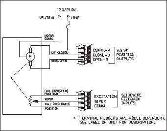
Valve Positioner Wiring
Units with Valve Positioner option have three output connections for controlling the valve motor and three input connections for slidewire feedback. The valve motor output connects to terminals labeled “Valve Position Outputs”, terminals 1, 2 and 3. See Figure 9, Valve Positioner Wiring for more details. Terminal 1 is the Valve motor supply common. Terminal 2 is the Valve Close or CW output. Terminal 3 is the Valve Open or CCW output. The valve motor common must be fused with a suitable value.
Figure 9, Valve Positioner Wiring
Although RC snubbers are employed inside the controller to suppress inductive “kicks” from the motor, it may be necessary to take further action to reduce noise effects:
1)Use Triac Output Modules wherever possible. The Triac device significantly reduces radiated EMI (Electromagnetic Interference).
The Triac Output Module also does not suffer from mechanical wear of the contacts.
2)Use RC snubbers directly across the valve motor.
3)Use a separate AC supply for the valve motor.
Where possible, the valve motor control outputs and the slidewire feedback input routing should be physically separated. Noise interference from the outputs could couple into the slidewire feedback inputs, disrupting proper operation.
The slidewire feedback inputs connect to the terminals labeled “Slidewire Feedback Inputs”. The terminal placement varies with each model, see the controller label for the actual terminals. For Velocity mode valve control the slidewire feedback inputs are not necessary.
In some cases, it may be desirable to have an independent valve position indicator. Red Lion Controls Model IMD1 can be wired in parallel with the slidewire input’s Wiper and Comm. terminals for this purpose. The approximate 0 to 0.9 V signal can be scaled to indicate percent valve position.
Linear DC Output Wiring
Units with Linear DC output option have two terminals to output a 4 to 20 mA or 0 to 10 VDC signal. The type of Linear DC output is determined by the model ordered. (See Ordering Information page 90, for available models.) These terminals are labeled “4-20 mA (or 0-10 VDC) Analog Output Option, Out+ and Out-”. The common of this output is isolated from thermocouple common , but is not isolated from the Second Analog Input Option common. For proper operation always keep these commons isolated.
Second Analog Input Wiring
Units with Second Analog Input option have two input terminals to receive a 4 to 20 mA signal. These terminals are labeled “Second Input, 4-20 mA+ and 4-20 mA-”. Terminal placement varies with model. See unit label for actual terminals. The common of this input is isolated from thermocouple common, but is not isolated from the Linear DC Output common. For proper operation always keep these commons isolated.
10
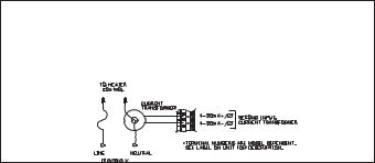
Heater Current Monitor Wiring
Units with Heater Current Monitor option have two input terminals to receive the output directly from a 100 mA current transformer.
Caution: Never connect a current transformer with a rating other than 100 mA.
These terminals are labeled “Second Input CT”, see Figure 10, Heater Current Wiring. Terminal placement varies with model. See controller label for actual terminals. There is no polarity observation for these inputs.
Figure 10, Heater Current Wiring
Program Disable Or User Input Wiring
Some models have Terminal #7 as the User Input, which is programmable for a variety of functions. Other models have Terminal #7 dedicated to the program disable function. Any form of mechanical switch may be connected to terminal #7. Sinking open collector logic with less than 0.7 V saturation may also be used (no pull-up resistance is necessary).
Note: Do not tie the commons of multiple units to a single switch. Use either a multiple pole switch for ganged operation or a single switch for each unit.
AC Power Wiring
Primary AC power is connected to the separate two position terminal block labeled AC. To reduce the chance of noise spikes entering the AC line and affecting the controller, an AC feed separate from that of the load should be used to power the controller. Be certain that the AC power to the controller is relatively “clean” and within the -15%, +10% variation limit. Connecting power from heavily loaded circuits or circuits that also power loads that cycle on and off, (contacts, relays, motors, etc.) should be avoided.
11
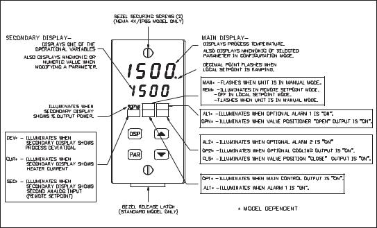
FRONT PANEL DESCRIPTION
The front panel bezel material is flame and scratch resistant, tinted plastic. An optional NEMA 4X/IP65 bezel version is available that meets NEMA 4X/IP65 requirements, when properly installed. There are two 4-digit LED displays, a red upper Main Display and a lower green Secondary Display.
There are up to six annunciators depending on options installed, with red backlighting, that illuminate to inform the operator of the controller and output status. See Figure 11, Front Panel for a description of the available annunciators.
Four front panel buttons are used to access different modes and parameters. The following is a description of each button.
Button Functions
DSP - In the normal operating mode, the Display (DSP) button
is used to select one of the operational parameters in the secondary display or the temperature unit’s (°F or °C). In the Configuration Parameter
Modes, pressing this button causes the unit to exit (escape) to the normal operating mode with no changes made to the selected parameter.
UP, DN - In the normal operating mode, the Up/Down buttons can be used to directly modify the setpoint value or % output power (manual mode only),
Figure 11, Front Panel
when viewed in the secondary display. Otherwise, the parameter must be called to alter the value.
PAR - The Parameter (PAR) button is used to access, enter the change, and scroll through the available parameters in any mode.
12
OPERATION OVERVIEW
Controller Power-up
Upon applying power, the controller delays control action and temperature indication for five seconds to perform several self-diagnostic tests and display basic controller information. Initially, the controller illuminates both displays and all annunciators to verify that all display elements are functioning. The controller then displays the programmed input sensor type in the main display (verify that the input select sensor jumper matches the programming). Concurrently, it displays the current revision number of the operating system software in the bottom display. The controller checks for correct internal operation and displays an error message (E-XX) if an internal fault is detected (see Troubleshooting, page 78, for further information).
Upon completion of this sequence, the controller begins control action by displaying the temperature and updating the outputs based upon the PID control calculation.
Controller Power Down
At power down, the steady state control value as well as all parameters and control modes are saved, to provide a quick and predictable temperature response on the next power-up.
When powering down the process, it is important to power down the controller at the same time. This prevents the reset action of the controller from shifting the proportional band while the temperature is dropping and prevents excessive overshoot on the next process start-up.
Process Start-up
After starting the process, the controller’s PID settings must be initially “tuned” to the process for optimum temperature control. Minimal tuning consists of adjusting the Proportional Band, Integral Time, and Derivative Time parameters to achieve the optimum response to a process disturbance. The controller can be tuned once, but must be re-tuned if the process has been changed significantly. Several options exist for tuning these parameters:
A)Use the controller’s built-in Auto-Tune feature (see Auto-Tune, page 68).
B)Use a manual tuning technique (see Manual Tuning, page 81).
C)Use a third party tuning software package (generally expensive and not always precise).
D) Use values based on control loop experience, calculated values or values from a similar process.
If the controller is a replacement, the PID settings from the unit being replaced may be used as good initial values. Be sure to consider any differences in the units and the PID settings when replacing. The PID settings may be fine tuned by using the techniques outlined in the PID Control section. After tuning the controller to the process, it is important to power the load and the controller at the same time for best start-up response.
Manual (User) & Automatic Operation
The controller can be transferred between Automatic control (closed loop; PID or ON/OFF control) and Manual control (open loop). In the Hidden Function Mode, the “trnf” parameter allows the operator to select the desired operating mode. To allow front panel switching between control modes, program the transfer (trnf) parameter to “Enbl” in the Lockout Module. The user input or RS485 serial interface option may also be used to perform the auto/manual transfer function, independent of the setting in the Lockout Module.
Manual operation provides direct control of the output(s) from 0 to +100%, or -100% to +100% if cooling output is installed. For Valve Positioner models with slidewire feedback, this mode allows manual valve positioning. The MAN (REM for Remote Setpoint models) annunciator flashes to indicate that the unit is in manual operation. When transferring the controller mode from/to automatic, the control power output(s) remain constant, exercising true “bumpless” transfer. When transferring from manual to automatic, the power initially remains steady but integral action corrects (if necessary) the closed loop power demand at a rate proportional to the Integral Time. The programmable high and low power limit values are ignored when the unit is in manual operation.
13
Remote And Local Setpoint Operation
The controller setpoint mode can be switched between Local Setpoint operation and Remote Setpoint operation. In the Hidden Function Mode, the “SPSL” parameter allows the operator to select the desired setpoint operating mode. To allow front panel switching between setpoint modes, program the setpoint select parameter (SPSL) to “Enbl” in the Lockout Module. The user input or RS485 serial interface option may also be used to perform the setpoint selection function, independent of the setting in the Lockout Module. Front panel annunciator REM is on for Remote setpoint operation and is off for Local setpoint operation. When transferring the controller mode from/to the setpoint modes, various controller response options are available (see SPtr parameter, page 38).
14

Configuration Of Parameters
As supplied from the factory, the controller parameters have been programmed to the values listed in the Programming Quick Reference Tables. The user must modify the values, if necessary, to suit the application.
Operation and configuration of the controller is divided into five distinct operational/programming modes to simplify the operation of the controller: Normal Display Mode, Unprotected Parameter Mode, Protected Parameter Mode, Hidden Function Mode, and Configuration Parameter Modules. See Figure 12, Operational/Programming Modes.
Figure 12, Operational/Programming Modes
15
Parameter Entry
The PAR button is used to select the desired parameter. To modify the parameter setting use the UP and DOWN buttons. Press PAR to enter the new value. The controller progresses to the next parameter. In a Configuration Parameter Module, pressing the DSP button causes the new value to be rejected, the controller displays “End”, and returns to the Normal Display Mode. For those parameters outside the Configuration Parameter Modules, the new value takes effect and is committed into controller memory WHILE the value is keyed in. The following is a list of commonly modified parameters:
Setpoint Output Power
Output Power Offset
Proportional Band Integral Time Derivative Time Proportional Band #2 Integral Time #2 Derivative Time #2
Directed Setpoint (Cascade) Ratio
Bias
Alarm 1 Value
Alarm 2 Value
Note: While in a Configuration Parameter Module, all new parameters are rejected and the old ones recalled if power is removed from the controller. If power is removed while modifying any parameter, be certain to check the parameter for the proper value.
Normal Display Mode
In the normal display mode, the process temperature is always displayed in the main display. By successively pressing the DSP button, one of these operational parameters can be viewed in the secondary display (model dependent):
Temperature Setpoint % Output Power Heater Current
Second Analog Input (Remote Setpoint) Temperature Setpoint Deviation Temperature Units Symbol (°F or °C).
Each of these displays can be independently locked out from appearing or from being modified by the user (see Lockouts Module, page 28). Only from the normal display mode can access be gained to the other modes (Unprotected, Protected, or Hidden).
Modifying A Secondary Display Parameter From The Front Panel
The controller must be in the normal display mode to modify the secondary display parameters. The Temperature Setpoint value and % output power (in manual mode) are the two parameters which may be modified. The other parameters are read-out values only.
Temperature Setpoint Value - Use the up and down arrow buttons to modify the setpoint value when viewed, if not locked. If locked, the setpoint can be changed in the unprotected mode when “SP” is viewed, independent of viewing in the secondary display. The setpoint value is confined to the programmable setpoint limit values (SPLO & SPHI, Input Module 1).
%Output Power - The % Output Power can only be changed when the unit is in the manual mode. See Manual (User) and Automatic Operations, page 13. The annunciator %PW lights, and the Manual annunciator flashes when viewed. Use the up and down arrow buttons to modify the % Output Power if not locked. If locked, the % output power can be changed in the unprotected mode when “OP” is viewed, independent of viewing in the secondary display. The % output power is not confined to the programmable output power limit values (OPLO & OPHI, Output Module 2).
16
UNPROTECTED PARAMETER MODE
The Unprotected Parameter Mode is accessed by pressing the PAR button from the normal display mode with program disable inactive. In this mode, the operator has access to the list of the most commonly modified controller parameters. At the end of the list, a configuration “access point” allows the operator to enter the configuration parameter modules. These modules allow access to the fundamental set-up parameters of the controller. When the program list has been scrolled through, the controller displays “End” and returns to the normal display mode. The unit automatically returns to the normal display mode if no action is taken.
Unprotected Parameter Mode Reference Table
|
|
Range and |
Description/ |
|
Display |
Parameter |
Units (Factory |
||
Comments |
||||
|
|
Setting Value) |
||
|
|
|
||
SP |
Temperature |
Confined to |
Appears only if setpoint value is |
|
|
Setpoint |
range of limits |
locked (LOC) or read only (rEd). |
|
|
|
SPLO, SPHI, 1 |
|
|
|
|
or 0.1 degree |
|
|
|
|
(0) |
|
|
OPOF |
%Output |
-99.9% to |
Appears only if integral time |
|
|
Power |
100% |
(Intt) = 0 and controller is in |
|
|
Offset |
(0.0) |
automatic mode. |
|
OP |
Output |
-99.9% to |
Appears only if controller is in |
|
|
Power |
100% |
user (manual) mode and % |
|
|
|
(0.0) |
output power is (LOC) or read |
|
|
|
|
only (rEd). This parameter is not |
|
|
|
|
limited to output power limits |
|
|
|
|
(OPLO & OPHI). |
|
Prop |
Proportional |
0.0 to 999.9% of |
0.0% is ON/OFF control. If using |
|
|
Band |
selected input |
ON/OFF mode, set control |
|
|
|
range |
hysteresis appropriately. |
|
|
|
(4.0) |
|
|
Intt |
Integral |
0 to 9999 sec. |
0 is off. This parameter does not |
|
|
Time |
(120) |
appear if proportional band = |
|
|
|
|
0.0%. |
|
dErt |
Derivative |
0 to 9999 sec. |
0 is off. This parameter does not |
|
|
Time |
(30) |
appear if proportional band = |
|
|
|
|
0.0%. |
|
Pb-2 |
Proportional |
0.0 to 999.9% of |
0.0% is ON/OFF control. |
|
|
Band #2 |
Scaled input |
Second Analog Input models |
|
|
(Secondary) |
range |
only. |
|
|
|
(4.0) |
|
|
It-2 |
Integral |
0 to 9999 sec. |
0 is off. This parameter does not |
|
|
Time #2 |
(0) |
appear if proportional band #2 = |
|
|
(Secondary) |
|
0.0%. Second Analog Input |
|
|
|
|
models only. |
17
|
|
Range and |
Description/ |
|
Display |
Parameter |
Units (Factory |
||
Comments |
||||
|
|
Setting Value) |
||
|
|
|
||
dt-2 |
Derivative |
0 to 9999 sec. |
0 is off. This parameter does not |
|
|
Time #2 |
(0) |
appear if proportional band #2 = |
|
|
(Secondary) |
|
0.0%. Second Analog Input |
|
|
|
|
models only. |
|
SP-2 |
Internal |
-999 to 9999 |
Second Analog Input models |
|
|
Cascade |
(N/A) |
only. Read only parameter. |
|
|
Directed |
|
|
|
|
Setpoint |
|
|
|
rtio |
Remote |
0.001 to 9.999 |
Second Analog Input models. |
|
|
Setpoint ratio |
(1.000) |
|
|
|
multiplier |
|
|
|
bIAS |
Remote |
0 to 9999 |
Second Analog Input models. |
|
|
Setpoint bias |
(0) |
|
|
|
offset |
|
|
|
AL-1 |
Alarm 1 |
-999 to 9999, 1 |
Alarm option models only. |
|
|
Value |
or 0.1 degree |
|
|
|
|
(0) |
|
|
AL-2 |
Alarm 2 |
-999 to 9999, 1 |
This parameter does not appear if |
|
|
Value |
or 0.1 degree |
the alarm option is not specified, |
|
|
|
(0) |
the cooling option is installed, or |
|
|
|
|
if locked (LOC). |
|
CNFP |
Configuration |
NO |
Return to normal display mode. |
|
|
Access |
|
Enter Configuration modules. |
|
|
Point |
1-IN |
Configure input parameters. |
|
|
|
2-OP |
Configure output parameters. |
|
|
|
3-LC |
Configure parameter lockouts. |
|
|
|
4-AL |
Configure alarm parameters (opt.) |
|
|
|
5-02 |
Configure cooling output (opt.) |
|
|
|
6-SC |
Configure serial communication |
|
|
|
|
parameters (optional) |
|
|
|
7-2N |
Configure second analog input |
|
|
|
|
parameters (optional) |
|
|
|
8-VP |
Configure valve positioner |
|
|
|
|
parameters (optional) |
|
|
|
9-FS |
Factory service operations |
|
|
|
|
(Qualified technicians only) |
|
End |
Unit returns |
____ |
Brief display message. |
|
|
to Normal |
|
|
|
|
Display Mode |
|
|
18
PROTECTED PARAMETER MODE
The Protected Parameter Mode is accessed from the normal display mode by pressing the PAR button with program disable active. In this mode, the operator has access to the list of the most commonly modified controller parameters that have been “unlocked” in the configuration parameter lockouts module. Depending on the code number entered in the lockout
Protected Parameter Mode Reference Table
|
|
Range and |
|
Display |
Parameter |
units (Factory |
Description/Comments |
|
|
Setting Value) |
|
Prop |
Proportional |
0.0 to 999.9% |
0.0% is ON/OFF control. If using |
|
Band |
of selected |
ON/OFF mode, set control |
|
|
input range |
hysteresis appropriately. This |
|
|
(4.0) |
parameter does not appear if |
|
|
|
locked (LOC). |
Intt |
Integral |
0 to 9999 sec. |
0 is off. This parameter does not |
|
Time |
(120) |
appear if proportional band = 0.0% |
|
|
|
or locked (LOC). |
dErt |
Derivative |
0 to 9999 sec. |
0 is off. This parameter does not |
|
Time |
(30) |
appear if proportional band = 0.0% |
|
|
|
or locked (LOC). |
Pb-2 |
Proportional |
0.0 to 999.9% |
0.0% is ON/OFF control. Second |
|
Band #2 |
of scaled input |
Analog Input models only. |
|
(Secondary) |
range |
|
|
|
(4.0) |
|
It-2 |
Integral |
0 to 9999 sec. |
0 is off. This parameter does not |
|
Time #2 |
(0) |
appear if proportional band #2= |
|
(Secondary) |
|
0.0%, or if locked (LOC). Second |
|
|
|
Analog Input models only. |
dt-2 |
Derivative |
0 to 9999 sec. |
0 is off. This parameter does not |
|
Time #2 |
(0) |
appear if proportional band #2= |
|
(Secondary) |
|
0.0%, or if locked (LOC). Second |
|
|
|
Analog Input models only. |
SP-2 |
Internal |
-999 to 9999 |
Second Analog Input models only. |
|
Cascade |
(N/A) |
Read only parameter. |
|
Directed |
|
|
|
Setpoint |
|
|
module, access to the unprotected parameter mode and hence, the configuration parameter modules is possible. The controller returns to the normal display mode if the unprotected mode and configuration modules cannot be accessed. This mode cannot be accessed if all parameters are locked out in Configuration Module 3.
|
|
Range and |
|
Display |
Parameter |
units (Factory |
Description/Comments |
|
|
Setting Value) |
|
rtio |
Remote |
0.001 to 9.999 |
Second Analog Input models only. |
|
setpoint |
(1.000) |
|
|
ratio |
|
|
|
multiplier |
|
|
bIAS |
Remote |
0 to 9999 |
Second Analog Input models only. |
|
setpoint |
(0) |
|
|
bias offset |
|
|
AL-1 |
Alarm 1 |
-999 to 9999 |
Alarm option models only. |
|
value |
1 or 0.1 degree |
|
|
|
(0) |
|
AL-2 |
Alarm 2 |
-999 to 9999 |
This parameter does not appear if |
|
value |
1 or 0.1 degree |
the alarm option is not specified, |
|
|
(0) |
the cooling option is installed, or if |
|
|
|
locked (LOC). |
Code |
Access |
0 to 250 |
To gain access to unprotected |
|
code to |
(0) |
mode, enter the same value for |
|
unprotected |
|
Code as entered in parameter |
|
mode |
|
lockouts. This parameter does not |
|
|
|
appear if zero is entered in code |
|
|
|
parameter lockout. |
End |
Unit returns |
|
Brief display message display |
|
to normal |
|
mode. |
|
display |
|
|
|
mode. |
|
|
19
Front Panel Program Disable
There are several ways to limit the programming of parameters from the front panel buttons. The settings of the parameters in the Lockout Module, the code number entered, and the state and/or function programmed for the User Input (Terminal #7) affect front panel access.
It is possible to have the program disable function on versions with the User Input, even if the User Input is not programmed for program disable (PLOC), by the use of a code number. Versions that do not have the User Input are dedicated to the program disable function.
The following charts describe the possible program disable settings depending on your model.
Models With User Input
User Input State |
Code Number |
Description |
Inactive or User |
0 |
Full access to all modes and |
Input not |
|
parameter modules. |
programmed for |
|
|
PLOC |
|
|
Active with User |
0 |
Access to protected parameter |
Input programmed |
|
mode only. Code number does not |
for PLOC |
|
appear. |
Active with User |
Any # between |
Access to protected parameter |
Input programmed |
1 & 250 |
mode. Correct programmed code |
for PLOC |
|
number allows access to |
OR |
|
unprotected parameter mode and |
User Input not |
|
configuration modules. |
programmed for |
|
|
PLOC |
|
|
Note: A universal code number 222 can be entered to gain access to the unprotected mode and configuration modules, independent of the programmed code number.
Models With Program Disable
Program Disable |
Code Number |
Description |
Inactive |
0 |
Full access to all modes and |
|
|
parameter modules. |
Active |
0 |
Access to protected parameter |
|
|
mode only. Code number does not |
|
|
appear. |
Active |
Any # between |
Access to protected parameter |
|
1 & 250 |
mode. Correct programmed code |
|
|
number allows access to |
|
|
unprotected parameter mode and |
|
|
configuration modules. |
Note: A universal code number 222 can be entered to gain access to the unprotected mode and configuration modules, independent of the programmed code number.
20
HIDDEN FUNCTION MODE
The Hidden Function Mode is only accessible from the normal display mode by pressing and holding the PAR button for three seconds. These functions must be unlocked in Configuration Module #3. Factory settings are locked. In this mode, these controller functions can be performed.
Local/Remote Setpoint Selection Automatic/Manual Transfer Initiate/Cancel Auto-tune
Reset Alarm Events
Each function may be “locked out” in the Configuration parameter lockouts module. The PAR button is used to scroll to the desired function and the up and down buttons are used to select the operation. Pressing the PAR button while the function is displayed executes the function, and returns the unit to the normal display mode. Pressing the DSP button exits this mode with no action taken. The unit automatically returns to the normal display mode if no action is taken.
Hidden Function Mode Reference Table
Display |
Parameter |
Range and Units |
Description/ |
(Factory Setting Value) |
Comments |
||
SPSL |
Select |
LOC - Local Setpoint |
Appears only for models |
|
Local or |
rE_t - Remote Setpoint |
with Second Analog Input. |
|
Remote |
(LOC) |
“SPtr” determines nature of |
|
Setpoint |
|
controller response. |
trnF |
Transfer |
Auto - Automatic control |
This step does not appear |
|
mode of |
User - Manual control |
if locked (LOC). Exits to |
|
operation |
(Auto) |
normal display mode if |
|
|
|
executed. |
tUNE |
Auto-tune |
Yes: starts the |
This step does not appear |
|
invocation |
auto-tune sequence. |
if locked (LOC) or exits to |
|
|
No: terminates the |
normal display mode if |
|
|
auto-tune sequence. |
executed. |
|
|
Prl - tune primary |
These parameters appear |
|
|
(Cascade) |
only if Second Analog |
|
|
SEC - tune secondary |
Input Internal Cascade is |
|
|
(Cascade) |
selected. |
|
|
(NO) |
|
ALrS |
Alarm reset |
UP key resets Alarm 1 |
This step does not appear |
|
|
DOWN key resets |
if alarm option not |
|
|
Alarm 2 |
installed, if locked (LOC) or |
|
|
|
previous step performed. |
21
CONFIGURATION PARAMETER MODULES
Accessible from the unprotected parameter mode, the configuration parameter modules allow the operator access to the controller’s fundamental set-up parameters. There are nine possible configuration stages that can be accessed. At the configuration stage access point “CNFP”, the operator uses the UP & DOWN arrow buttons to select the desired configuration parameter module. Press the PAR button to enter the module where the settings can be viewed or modified. The PAR button is used to scroll through the parameters and the UP and DOWN buttons are used to modify the parameter value. The PAR button enters the desired choice, advancing to the next parameter. The operator can press the DSP button to exit (escape) without modifying the parameter. The unit returns to the normal display mode. After the parameters in a module are viewed or modified, the unit returns to the configuration access point, allowing access to other modules.
Input Module (1- In)
The controller has several input set-up parameters that must be programmed prior to setting any other controller parameters.
Input Type (type)
Select from the list of various thermocouple and RTD sensors. Be sure to set the internal input select jumper to the appropriate position (TC or RTD, see Select Input Sensor Type, page 7, or the label on outside of case for location of jumper).
The following is a list of the possible sensors:
tc-t |
- |
Type T TC |
tc-E |
- |
Type E TC |
tc-J |
- |
Type J TC |
tc-k |
- |
Type K TC |
tc-r |
- |
Type R TC |
tc-S |
- |
Type S TC |
tc-B |
- |
Type B TC |
tc-N |
- |
Type N TC |
LIN |
- |
Linear mV display |
r385 |
- |
385 curve RTD |
r392 |
- |
392 curve RTD |
rLIN |
- |
Linear ohms display |
Temperature Scale (SCAL)
Select either degrees Fahrenheit (F) or degrees Celsius (C). If changed, be sure to check All parameters.
Temperature Resolution (dCPt)
Select either 1 or 0.1 degree resolution. If changed, be sure to check All parameters.
Input Signal Filter and Display Update Rate (FLtr)
Select the relative degree of input signal filtering and display update rate. The filter is an adaptive digital filter that discriminates between measurement noise and actual process changes. Therefore, the influence on step response time is minimal. If the signal is varying too greatly due to measurement noise, increase the filter value. Additionally, with large derivative times, control action may be too unstable for accurate control. Increase the filter value. Conversely, if the fastest controller response is desired, decrease the filter value.
The Auto-tune procedure sets the filter value appropriate to the process characteristics. Also see Output Power Dampening parameter (OPdP), page 26, for filtering the output.
Fltr- 0 to 4
0 = least input filtering
3= most input filtering
4= most input filtering and slower (2/sec) display update rate (outputs update at 10/sec rate)
22
 Loading...