


Bulletin No. PAXDP-K Drawing No. LP0578 Released 11/12
Tel +1 (717) 767-6511
Fax +1 (717) 764-0839 www.redlion.net
MODEL PAXDP – 1/8 DIN DUAL PROCESS INPUT METER
C UR L US LISTED
IND. CONT. EQ.
51EB
ACCEPTS TWO 4 - 20 mA OR 0 - 10 VDC INPUT SIGNALS
PROGRAMMABLE A/D CONVERSION RATE, 5 TO 105 READINGS PER SECOND
5-DIGIT 0.56" RED SUNLIGHT READABLE DISPLAY
VARIABLE INTENSITY DISPLAY
LINEARIZATION/SQUARE ROOT EXTRACTION INPUT RANGE
PROGRAMMABLE FUNCTION KEYS/USER INPUTS
9 DIGIT TOTALIZER (INTEGRATOR) WITH BATCHING
OPTIONAL CUSTOM UNITS OVERLAY W/BACKLIGHT
FOUR SETPOINT ALARM OUTPUTS (W/OPTION CARD)
COMMUNICATION AND BUS CAPABILITIES (W/OPTION CARD)
RETRANSMITTED ANALOG OUTPUT (W/OPTION CARD)
NEMA 4X/IP65 SEALED FRONT BEZEL
PC SOFTWARE AVAILABLE FOR METER CONFIGURATION
GENERAL DESCRIPTION
The PAXDP Dual Process Input Meter offers many features and performance capabilities to suit a wide range of industrial applications. Available in two models, AC or DC power, the meter has the capability to accept two, 4 to 20 mA or 0 to 10 VDC input signals. Each input signal can be independently scaled and displayed. In addition, a math function can be performed on the two signals, C + A + B, C - A - B, C + A - B, AB / C, CA / B, or C (A / B - 1). Any of the three meter values can have Alarms, Comms, and/or a Retransmitted Analog Output capability by simply adding optional cards. The optional plug-in output cards allow the opportunity to configure the meter for current applications, while providing easy upgrades for future needs.
The update rate of the meter is user selectable. This will help in those applications where a quick response from the meter is of the utmost importance. The rate can be adjusted from eight selections with a minimum of 5 updates/ second to a maximum of 105 updates/second.
The meters employ a bright 0.56" (14.2 mm) red sunlight readable LED display. The intensity of display can be adjusted from dark room applications up to sunlight readable, making it ideal for viewing in bright light applications.
The meters provide a MAX and MIN reading memory with programmable capture time. The capture time is used to prevent detection of false max or min readings which may occur during start-up or unusual process events.
The signal totalizer (integrator) can be used to compute a time-input product. This can be used to provide a readout of totalized flow, calculate service intervals of motors or pumps, etc. The totalizer can also accumulate batch operations.
The meter has four setpoint outputs, implemented on Plug-in option cards. The Plug-in cards provide dual FORM-C relays (5A), quad FORM-A (3A), or either quad sinking or quad sourcing open collector logic outputs. The setpoint alarms can be configured to suit a variety of control and alarm requirements.
Communication and Bus Capabilities are also available as option cards. The standard output is in Modbus Protocol. Any of the following option cards, RS232, RS485, DeviceNet, or Profibus can be used with the meter. Readout
values and setpoint alarm values can be controlled through the bus. Additionally, the meters have a feature that allows a remote computer to directly control the outputs of the meter.
A linear DC output signal is available as an optional Plug-in card. The card provides either 20 mA or 10 V signals. The output can be scaled independent of the input range and can track either the input, totalizer, max/min readings, or math calculation value.
Once the meters have been initially configured, the parameter list may be locked out from further modification in its entirety or only the setpoint values can be made accessible.
The meters have been specifically designed for harsh industrial environments. With NEMA 4X/IP65 sealed bezel and extensive testing of noise effects to CE requirements, the meter provides a tough yet reliable application solution.
SAFETY SUMMARY
All safety related regulations, local codes and instructions that appear in this literature or on equipment must be observed to ensure personal safety and to prevent damage to either the instrument or equipment connected to it. If equipment is used in a manner not specified by the manufacturer, the protection provided by the equipment may be impaired.
Do not use this unit to directly command motors, valves, or other actuators not equipped with safeguards. To do so can be potentially harmful to persons or equipment in the event of a fault to the unit.
CAUTION: Risk of Danger. |
CAUTION: Risk of electric shock. |
Read complete instructions prior to |
|
installation and operation of the unit. |
|
DIMENSIONS In inches (mm)
A |
8.8.8.8.8 V |
1.95 |
C |
||
B |
|
|
SP1 |
SP2 |
SP3 |
SP4 |
(49.5) |
DSP |
PAR F1 |
F2 |
RST |
|
|
3.80 |
|
.10 |
|
|
(96.5) |
|
(2.5) |
|
Note: Recommended minimum clearance (behind the panel) for mounting clip installation is 2.1" (53.4) H x 5.0" (127) W.
|
|
|
|
|
|
|
|
12 |
|
|
16 |
20 |
|
|
|
|
|
|
|
|
|
13 |
|
|
17 |
21 |
|
1.75 |
|
|
|
|
|
|
|
14 |
|
|
18 |
22 |
1.75 |
1 |
2 |
3 |
4 |
5 |
6 |
7 |
15 |
9 |
10 |
19 |
23 |
||
(44.5) |
8 |
11 |
25 |
(44.5) |
|||||||||
|
|
|
|
|
|
|
|
|
|
|
|
24 |
|
4.10 |
|
|
|
|
3.60 (91.4) |
|
|
||||||
(104.1) |
|
|
|
|
|
|
|||||||
|
|
|
|
|
|
|
|
|
|
|
|
|
|
1 |
|
|
|
|
|
|
|
|
|
|
|
|
|

Table Of Contents
Ordering Information . . . . |
. . . . . |
. |
2 |
Wiring the Meter. . . . . . . . . . . |
. |
6 |
General Meter Specifications . . |
. . . . . |
|
3 |
Reviewing the Front Buttons and Display.. |
. |
8 |
Accessories. . . . . . . . . . . . . . 4 |
Programming the Meter. . . . . . . . . . . . . . . |
. . |
. 9 |
|||
Optional Plug-In Cards. . . . |
. . . . . |
|
. 4 |
Factory Service Operations . . . . . . |
. |
27 |
Installing the Meter. . . . . |
. . . . . |
. |
5 |
Troubleshooting Guide . . . . . . . . |
. |
28 |
Setting the Jumpers . . . . . |
. . . . . |
|
. 5 |
Parameter Value Chart . . . . . . . . |
|
28 |
Installing Plug-In Cards. . . . |
. . . . . |
|
. 6 |
Programming Overview . . . . . . . . |
. 30 |
|
Ordering Information
Meter Part Numbers
PAX |
|
|
|
|
0 |
|
|
|
|
|
|
|
|
|
|
|
|
DP - Dual Process Input
0 - Red, Sunlight Readable Display
0 - 85 to 250 VAC
1 - 18 to 36 VDC, 24 VAC
Option Card and Accessories Part Numbers
TYPE |
MODEL NO. |
DESCRIPTION |
PART NUMBER |
|
|
|
Dual Setpoint Relay Output Card |
PAXCDS10 |
|
|
PAXCDS |
Quad Setpoint Relay Output Card |
PAXCDS20 |
|
|
|
|
||
|
Quad Setpoint Sinking Open Collector Output Card |
PAXCDS30 |
||
|
|
|||
|
|
Quad Setpoint Sourcing Open Collector Output Card |
PAXCDS40 |
|
|
|
|
|
|
|
|
RS485 Serial Communications Card with Terminal Block |
PAXCDC10 |
|
Optional |
|
Extended RS485 Serial Communications Card with Dual RJ11 Connector |
PAXCDC1C |
|
Plug-In |
|
|
|
|
|
RS232 Serial Communications Card with Terminal Block |
PAXCDC20 |
||
Cards |
PAXCDC |
|||
|
Extended RS232 Serial Communications Card with 9 Pin D Connector |
PAXCDC2C |
||
|
|
|||
|
|
DeviceNet Communications Card |
PAXCDC30 |
|
|
|
|
|
|
|
|
Profibus-DP Communications Card |
PAXCDC50 |
|
|
PAXCDL |
Analog Output Card |
PAXCDL10 |
|
|
PAXUSB |
PAX USB Programming Card (Not included in PAX product UL E179259 file) |
PAXUSB00 |
|
|
CBLUSB |
USB Programming Cable Type A-Mini B |
CBLUSB01 |
|
Accessories |
ICM8 |
Ethernet Gateway |
ICM80000 |
|
PAXLBK |
Units Label Kit Accessory |
PAXLBK10 |
||
|
||||
|
SFCRD * |
Crimson PC Configuration Software for Windows 98, ME, 2000 and XP |
SFCRD200 |
Notes:
1.For Modbus communications use RS485 Communications Output Card and configure communication ( ) parameter for Modbus.
2.Crimson® 2 software is available as a free download at http://www.redlion.net/
2

General Meter Specifications
1.DISPLAY: 5 digit, 0.56" (14.2 mm) variable intensity red sunlight readable (-19999 to 99999)
2.POWER: AC Versions:
AC Power: 85 to 250 VAC, 50/60 Hz, 21 VA
Isolation: 2300 Vrms for 1 min. to all inputs and outputs.
DC Versions: (Derate operating temperature to 40° C if three plug-in option cards or PAXCDC50 are installed.)
DC Power: 18 to 36 VDC, 13 W
AC Power: 24 VAC, ± 10%, 50/60 Hz, 16 VA
Isolation: 500 Vrms for 1 min. to all inputs and outputs (50 V working). Must use a Class 2 or SELV rated power supply
3.ANNUNCIATORS:
A - Programmable Display B - Programmable Display C - Programmable Display
SP1 - Setpoint alarm 1 is active SP2 - Setpoint alarm 2 is active SP3 - Setpoint alarm 3 is active SP4 - Setpoint alarm 4 is active
Units Label - Optional units label backlight
4.KEYPAD: 3 programmable function keys, 5 keys total
5.A/D CONVERTER: 16 bit resolution
6.UPDATE RATES:
A/D conversion rate: Adjustable 5.3 to 105 readings/sec.
Step response: (to within 99% of final readout value with digital filter disabled)
INPUT UPDATE RATE |
MAX. TIME (msec) |
5.3 |
770 |
7.5 |
560 |
16.7 |
260 |
19.8 |
220 |
20 |
220 |
30 |
150 |
105 |
60 |
Display update rate: adjustable 1 to 20 readings/sec.
Setpoint output on/off delay time: 0 to 3275 sec.
Analog output update rate: 0 to 10 sec
Max./Min. capture delay time: 0 to 3275 sec.
7.DISPLAY MESSAGES:
“OLOL” - Appears when measurement exceeds + signal range. “ULUL” - Appears when measurement exceeds - signal range “. . . .” - Appears when display values exceed + display range. “- . . .” - Appears when display values exceed - display range.
8.SENSOR INPUTS:
INPUT |
ACCURACY* |
ACCURACY* |
IMPEDANCE/ |
MAX |
DISPLAY |
|
CONTINUOUS |
||||||
(RANGE) |
(18 to 28°C) |
(0 to 50°C) |
COMPLIANCE |
RESOLUTION |
||
|
|
|
|
OVERLOAD |
|
|
±20 mA |
0.03% of |
0.12% of |
|
|
|
|
(-26 to |
24.6 ohm |
90 mA |
1 µA |
|||
reading +2 µA |
reading +3 µA |
|||||
26 mA) |
|
|
|
|
|
|
±10 VDC |
0.03% of |
0.12% of |
|
|
|
|
(-13 to |
500 Kohm |
50 V |
1 mV |
|||
reading +2 mV |
reading +3 mV |
|||||
13 VDC) |
|
|
|
|
|
*After 20 minute warm-up. Accuracy is specified in two ways: Accuracy over an 18 to 28°C and 10 to 75% RH environment; and accuracy over a 0 to 50°C and 0 to 85% RH (non-condensing environment). Accuracy over the 0 to 50°C range includes the temperature coefficient effect of the meter.
9.EXCITATION POWER:
Transmitter Power: 18 VDC, ±20%, unregulated, 70 mA max. per input channel.
10. LOW FREQUENCY NOISE REJECTION: Normal Mode: (digital filter off)
INPUT UPDATE RATE |
50 Hz ±1 Hz |
60 Hz ±1 Hz |
5.3 |
>90 dB |
>65 dB |
7.5 |
>60 dB |
>55 dB |
16.7 |
>100 dB |
>50 dB |
19.8* |
>60 dB |
>95 dB |
20 |
>55 dB |
>100 dB |
30 |
>20 dB |
>20 dB |
105 |
>20 dB |
>13 dB |
*Note: 19.8 Hz Input Rate provides best rate performance and simultaneous 50/60 Hz rejection.
Common Mode: >100 dB @ 50/60 ±1 Hz (19.8 or 20 Input Rate) 11. USER INPUTS: Three programmable user inputs
Max. Continuous Input: 30 VDC
Isolation To Sensor Input A Common: 500 Vrms for 1 min; Working Voltage: 50 V
Isolation To Sensor Input B Common: Not isolated.
INPUT STATE |
SINKING INPUTS |
SOURCING INPUTS |
|
22 KΩ pull-up to +5 V |
22 KΩ pull-down |
||
|
|||
Active |
VIN < 0.9 VDC |
VIN > 3.6 VDC |
|
Inactive |
VIN > 3.6 VDC |
VIN < 0.9 VDC |
Response Time: 20 msec. max.
Logic State: Jumper selectable for sink/source logic
12.TOTALIZER: Function:
Time Base: second, minute, hour, or day
Batch: Can accumulate (gate) input display from a user input Time Accuracy: 0.01% typical
Decimal Point: 0 to 0.0000 Scale Factor: 0.001 to 65.000
Low Signal Cut-out: -19,999 to 99,999
Total: 9 digits, display alternates between high order and low order readouts
13.CUSTOM LINEARIZATION:
Data Point Pairs: Selectable from 2 to 16
Display Range: -19,999 to 99,999
Decimal Point: 0 to 0.0000
14.MEMORY: Nonvolatile memory retains all programmable parameters and display values.
15.CERTIFICATIONS AND COMPLIANCES:
CE Approved
EN 61326-1 Immunity to Industrial Locations Emission EN 55011 Class A
IEC/EN 61010-1
UL Recognized Component: File #E179259 UL Listed: File #E137808
Type 4X Enclosure rating (Face only) IP65 Enclosure rating (Face only) IP20 Enclosure rating (Rear of unit)
Refer to EMC Installation Guidelines section of the bulletin for additional information.
16. ENVIRONMENTAL CONDITIONS:
Operating Temperature Range: 0 to 50°C (0 to 45°C with all three plug-in option cards installed)
Storage Temperature Range: -40 to 60°C
Vibration to IEC 68-2-6: Operational 5-150 Hz, 2 g Shock to IEC 68-2-27: Operational 25 g (10 g relay)
Operating and Storage Humidity: 0 to 85% max. RH non-condensing Altitude: Up to 2000 meters
17.CONNECTIONS: High compression cage-clamp terminal block Wire Strip Length: 0.3" (7.5 mm)
Wire Gage: 30-14 AWG copper wire Torque: 4.5 inch-lbs (0.51 N-m) max.
18.CONSTRUCTION: This unit is rated for NEMA 4X/IP65 outdoor use.
IP20 Touch safe. Installation Category II, Pollution Degree 2. One piece bezel/case. Flame resistant. Synthetic rubber keypad. Panel gasket and mounting clip included.
19. WEIGHT: 10.4 oz. (295 g)
3

Accessories
UNITS LABEL KIT (PAXLBK)
Each meter has a units indicator with backlighting that can be customized using the Units Label Kit. The backlight is controlled in the programming.
PROGRAMMING SOFTWARE
The Crimson® 2 (SFCRM2) software is a Windows® based program for configuring and updating the firmware of the PAXDP meter from a PC. Using the software makes programming the PAXDP meter easier and allows the user to save the PAXDP database in a PC file for future use. The software is available as a free download from Red Lion’s website.
The first time Crimson 2 software is run from the File menu, select “New” to display a dialog and select the PAXDP. The screen will display icons that
represent the various programming sections of the PAXDP. Double-click on an icon to configure the programming parameters pertaining to the selection. Tool Tip help is available for each of the program parameters. A PAX serial plug-in card or PAX USB programming card is required to program the meter using the software.
When communicating with Crimson 2 software, the PAXDP must be set in default configuration type of:
Communications Type: MODBUS RTU Baud Rate: 38400
Data Bit: 8 ParityBit: no
Meter Unit Address: 247
Optional Plug-in Output Cards
WARNING: Disconnect all power to the unit before installing Plug-in cards.
Adding Option Cards
The PAX and MPAX series meters can be fitted with up to three optional plugin cards. The details for each plug-in card can be reviewed in the specification section below. Only one card from each function type can be installed at one time. The function types include Setpoint Alarms (PAXCDS), Communications (PAXCDC), and Analog Output (PAXCDL). The plug-in cards can be installed initially or at a later date.
COMMUNICATION CARDS (PAXCDC)
A variety of communication protocols are available for the PAX and MPAX series. Only one of these cards can be installed at a time. Note: For Modbus communications use RS485 Communications Output Card and configure communication ( ) parameter for Modbus.
PAXCDC10 - RS485 Serial (Terminal) |
PAXCDC30 - DeviceNet |
PAXCDC1C - RS485 Serial (Connector) |
PAXCDC50 - Profibus-DP |
PAXCDC20 - RS232 Serial (Terminal) |
PAXUSB00 - USB (Mini B) |
PAXCDC2C - RS232 Serial (Connector) |
|
SERIAL COMMUNICATIONS CARD Type: RS485 or RS232
Communication Type: RLC Protocol (ASCII), Modbus RTU, and Modbus ASCII
Isolation To Sensor & User Input Commons: 500 Vrms for 1 min. Working Voltage: 50 V. Not Isolated from all other commons.
Baud: 300 to 38,400 Data: 7/8 bits
Parity: No, Odd or Even
Bus Address: Selectable 0 to 99 (RLC Protocol), or 1 to 247 (Modbus Protocol), Max. 32 meters per line (RS485)
Transmit Delay: Selectable for 0 to 0.250 sec (+2 msec min)
DEVICENET™ CARD
Compatibility: Group 2 Server Only, not UCMM capable Baud Rates: 125 Kbaud, 250 Kbaud, and 500 Kbaud
Bus Interface: Phillips 82C250 or equivalent with MIS wiring protection per DeviceNet™ Volume I Section 10.2.2.
Node Isolation: Bus powered, isolated node
Host Isolation: 500 Vrms for 1 minute (50 V working) between DeviceNet™ and meter input common.
PROFIBUS-DP CARD
Fieldbus Type: Profibus-DP as per EN 50170, implemented with Siemens SPC3 ASIC
Conformance: PNO Certified Profibus-DP Slave Device
Baud Rates: Automatic baud rate detection in the range 9.6 Kbaud to 12 Mbaud Station Address: 0 to 125, set by rotary switches.
Connection: 9-pin Female D-Sub connector
Network Isolation: 500 Vrms for 1 minute (50 V working) between Profibus network and sensor and user input commons. Not isolated from all other commons.
PAXUSB PROGRAMMING CARD
Type: USB Virtual Comms Port
Connection: Type mini B
Isolation To Sensor & User Input Commons: 500 Vrms for 1 min. Working Voltage: 50 V. Not Isolated from all other commons.
Baud Rate: 300 to 19.2k
Unit Address: 0 to 99; only 1 meter can be configured at a time
SETPOINT CARDS (PAXCDS)
The PAX and MPAX series has 4 available setpoint alarm output plug-in cards. Only one of these cards can be installed at a time. (Logic state of the outputs can be reversed in the programming.) These plug-in cards include:
PAXCDS10 - Dual Relay, FORM-C, Normally open & closed PAXCDS20 - Quad Relay, FORM-A, Normally open only PAXCDS30 - Isolated quad sinking NPN open collector PAXCDS40 - Isolated quad sourcing PNP open collector
DUAL RELAY CARD Type: Two FORM-C relays
Isolation To Sensor & User Input Commons: 2000 Vrms for 1 min. Working Voltage: 240 Vrms
Contact Rating:
One Relay Energized: 5 amps @ 120/240 VAC or 28 VDC (resistive load), 1/8 HP @120 VAC, inductive load
Total current with both relays energized not to exceed 5 amps
Life Expectancy: 100 K cycles min. at full load rating. External RC snubber extends relay life for operation with inductive loads
QUAD RELAY CARD Type: Four FORM-A relays
Isolation To Sensor & User Input Commons: 2300 Vrms for 1 min. Working Voltage: 250 Vrms
Contact Rating:
One Relay Energized: 3 amps @ 240 VAC or 30 VDC (resistive load), 1/10 HP @120 VAC, inductive load
Total current with all four relays energized not to exceed 4 amps
Life Expectancy: 100 K cycles min. at full load rating. External RC snubber extends relay life for operation with inductive loads
QUAD SINKING OPEN COLLECTOR CARD Type: Four isolated sinking NPN transistors.
Isolation To Sensor & User Input Commons: 500 Vrms for 1 min. Working Voltage: 50 V. Not Isolated from all other commons.
Rating: 100 mA max @ VSAT = 0.7 V max. VMAX = 30 V
QUAD SOURCING OPEN COLLECTOR CARD Type: Four isolated sourcing PNP transistors.
Isolation To Sensor & User Input Commons: 500 Vrms for 1 min. Working Voltage: 50 V. Not Isolated from all other commons.
Rating: Internal supply: 24 VDC ± 10%, 30 mA max. total External supply: 30 VDC max., 100 mA max. each output
ALL FOUR SETPOINT CARDS
Response Time: See update rates step response specification; add 6 msec (typical)for relay card
4

LINEAR DC OUTPUT (PAXCDL)
Either a 0(4)-20 mA or 0-10 V retransmitted linear DC output is available from the analog output plug-in card. The programmable output low and high scaling can be based on various display values. Reverse slope output is possible by reversing the scaling point positions.
PAXCDL10 - Retransmitted Analog Output Card
ANALOG OUTPUT CARD
Types: 0 to 20 mA, 4 to 20 mA or 0 to 10 VDC
Isolation To Sensor & User Input Commons: 500 Vrms for 1 min. Working Voltage: 50 V. Not Isolated from all other commons.
Accuracy: 0.17% of FS (18 to 28°C); 0.4% of FS (0 to 50°C)
Resolution: 1/3500
Compliance: 10 VDC: 10 KΩ load min., 20 mA: 500 Ω load max. Powered: Self-powered
Step Response: See update rates step response specification
Update time: See ADC Conversion Rate and Update Time parameter
1.0 Installing the Meter
Installation
The PAX meets NEMA 4X/IP65 requirements when properly installed. The unit is intended to be mounted into an enclosed panel. Prepare the panel cutout to the dimensions shown. Remove the panel latch from the unit. Slide the panel gasket over the rear of the unit to the back of the bezel. The unit should be installed fully assembled. Insert the unit into the panel cutout.
PANEL
BEZEL
LATCHING |
PANEL |
|
SLOTS |
||
LATCH |
||
|
LATCHING
TABS
PANEL
GASKET
PANEL
MOUNTING
SCREWS
While holding the unit in place, push the panel latch over the rear of the unit so that the tabs of the panel latch engage in the slots on the case. The panel latch should be engaged in the farthest forward slot possible. To achieve a proper seal, tighten the latch screws evenly until the unit is snug in the panel (Torque to approximately 7 in-lbs [79N-cm]). Do not over-tighten the screws.
Installation Environment
The unit should be installed in a location that does not exceed the maximum operating temperature and provides good air circulation. Placing the unit near devices that generate excessive heat should be avoided.
The bezel should be cleaned only with a soft cloth and neutral soap product. Do NOT use solvents. Continuous exposure to direct sunlight may accelerate the aging process of the bezel.
Do not use tools of any kind (screwdrivers, pens, pencils, etc.) to operate the keypad of the unit.
PANEL CUT-OUT
3.62 |
+-.00.03 |
|
|
|
|
||
(92 |
+-.0.8 ) |
|
|
+.02 |
|||
|
|
1.77-.00 |
|
|
|
(45 +-.0.5 ) |
|
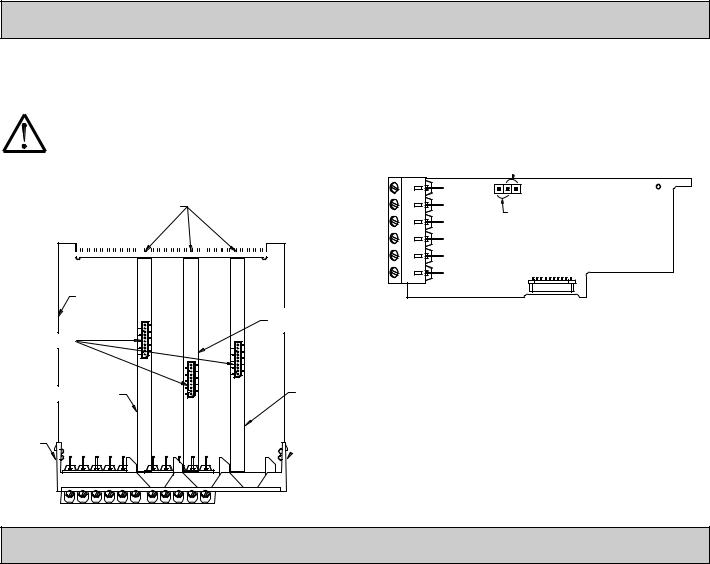
2.0 Setting the Jumpers
The meter has three jumpers that must be checked and/or changed prior to applying power. The following Jumper Selection Figures show an enlargement of the jumper area.
To access the jumpers, remove the meter base from the case by firmly squeezing and pulling back on the side rear finger tabs. This should lower the latch below the case slot (which is located just in front of the finger tabs). It is recommended to release the latch on one side, then start the other side latch.
Input Jumpers
These jumpers are used to select the proper input types, Voltage (V) or Current
(I). The input type selected in programming must match the jumper setting. See the Jumper Selection Figures for more details.
PAXDP Jumper Selection
JUMPER SELECTIONS
The  indicates factory setting.
INPUT A |
INPUT B |
|
|
|
|||||
VOLT/CURRENT |
VOLT/CURRENT |
USER INPUT |
|||||||
|
|
|
CURRENT (I) |
|
|
CURRENT (I) |
|
|
SINK |
|
|
||||||||
|
|
|
|
|
|
||||
|
|
|
VOLTAGE (V) |
|
|
VOLTAGE (V) |
|
|
SOURCE (SRC) |
|
|
|
|
|
|||||
Note: In the figures above, the text shown in parenthesis is printed on the circuit board to help with proper jumper positioning.
User Input Logic Jumper
This jumper selects the logic state of all the user inputs. If the user inputs are not used, it is not necessary to check or move this jumper.
FRONT DISPLAY
INPUT JUMPER LOCATIONS |
USER INPUT |
||
|
INPUT B |
||
(CURRENT) I |
JUMPER |
||
|
|||
|
LOCATION |
||
(VOLTAGE) V |
I |
||
|
|||
INPUT A |
V |
|
|
REAR TERMINALS
5
3.0 Installing Plug-In Cards
The plug-in cards are separately purchased optional cards that perform specific functions. These cards plug into the main circuit board of the meter. The plug-in cards have many unique functions when used with the PAX.
CAUTION: The plug-in card and main circuit board contain static sensitive components. Before handling the cards, discharge static charges from your body by touching a grounded bare metal object. Ideally, handle the cards at a static controlled clean workstation. Also, only handle the cards by the edges. Dirt, oil or other contaminants that may contact the cards can adversely affect circuit operation.
|
Alignment |
|
|
|
|
|||||
|
TOP VIEW |
|||||||||
|
|
|
Slots |
|
|
|
|
|
||
|
|
|
|
|
|
|
|
|
|
|
|
|
|
|
|
|
|
|
|
|
|
|
|
|
|
|
|
|
|
|
|
|
|
|
|
|
|
|
|
|
|
|
|
To Install:
1.With the meter removed from the case, locate the plug-in card connector for the card type to be installed. The types are keyed by position with different main circuit board connector locations. When installing the card, hold the meter by the rear terminals and not by the front display board.
If installing the Quad sourcing Plug-in Card (PAXCDS40), set the jumper for internal or external supply operation before continuing.
Internal Supply
 (18 V unregulated)
External Supply
(30 Vmax )
Main
Circuit
Board
Connectors
Serial
Communications
Card
Finger
Tab
Analog Output
Card
Setpoint
Output
Card
Finger
 Tab
Tab
2.Install the plug-in card by aligning the card terminals with the slot bay in the rear cover. Be sure the connector is fully engaged and the tab on the plug-in card rests in the alignment slot on the display board.
3.Slide the meter base back into the case. Be sure the rear cover latches fully into the case.
4.Apply the plug-in card label to the bottom side of the meter in the designated area. Do Not Cover the vents on the top surface of the meter. The surface of the case must be clean for the label to adhere properly.
4.0 Wiring the Meter
WIRING OVERVIEW
Electrical connections are made via screw-clamp terminals located on the back of the meter. All conductors should conform to the meter’s voltage and current ratings. All cabling should conform to appropriate standards of good installation, local codes and regulations. It is recommended that power supplied to the meter (DC or AC) be protected by a fuse or circuit breaker.
When wiring the meter, compare the numbers embossed on the back of the meter case against those shown in wiring drawings for proper wire position. Strip the wire, leaving approximately 0.3" (7.5 mm) bare lead exposed (stranded wires should be tinned with solder). Insert the lead under the correct screwclamp terminal and tighten until the wire is secure. (Pull wire to verify tightness.) Each terminal can accept up to one #14 AWG (2.55 mm) wire, two #18 AWG (1.02 mm), or four #20 AWG (0.61 mm).
EMC INSTALLATION GUIDELINES
Although this meter is designed with a high degree of immunity to ElectroMagnetic Interference (EMI), proper installation and wiring methods must be followed to ensure compatibility in each application. The type of the electrical noise, its source or the method of coupling into the unit may be different for various installations. Listed below are some EMC guidelines for successful installation in an industrial environment.
1.The meter should be mounted in a metal enclosure, which is properly connected to protective earth.
2.With use of the lower input ranges or signal sources with high source impedance, the use of shielded cable may be necessary. This helps to guard against stray AC pick-up. Attach the shield to the input common of the meter.
3.To minimize potential noise problems, power the meter from the same power branch, or at least the same phase voltage as that of the signal source.
4.Never run Signal or Control cables in the same conduit or raceway with AC power lines, conductors feeding motors, solenoids, SCR controls, and
heaters, etc. The cables should be run in metal conduit that is properly grounded. This is especially useful in applications where cable runs are long and portable two-way radios are used in close proximity or if the installation is near a commercial radio transmitter.
5.Signal or Control cables within an enclosure should be routed as far away as possible from contactors, control relays, transformers, and other noisy components.
6.In extremely high EMI environments, the use of external EMI suppression devices, such as ferrite suppression cores, is effective. Install them on Signal and Control cables as close to the unit as possible. Loop the cable through the core several times or use multiple cores on each cable for additional protection. Install line filters on the power input cable to the unit to suppress power line interference. Install them near the power entry point of the enclosure. The following EMI suppression devices (or equivalent) are recommended:
Ferrite Suppression Cores for signal and control cables: Fair-Rite # 0443167251 (RLC #FCOR0000)
TDK # ZCAT3035-1330A Steward #28B2029-0A0
Line Filters for input power cables:
Schaffner # FN2010-1/07 (RLC #LFIL0000) Schaffner # FN670-1.8/07
Corcom #1VR3
Note: Reference manufacturer’s instructions when installing a line filter.
7.Long cable runs are more susceptible to EMI pickup than short cable runs. Therefore, keep cable runs as short as possible.
8.Switching of inductive loads produces high EMI. Use of snubbers across inductive loads suppresses EMI.
Snubber: RLC#SNUB0000.
6

4.1 POWER WIRING
AC Power |
AC |
AC |
DC Power |
|||
Terminal 1: VAC |
Terminal 1: +VDC |
|||||
|
|
|
|
|||
Terminal 2: VAC |
1 |
2 |
Terminal 2: -VDC |
|||
|
|
|
|
|
|
|
DC+ |
|
DC- |
|||
1 |
|
|
|
|
|
|
|
2 |
|||
+ |
|
- |
|
||
|
|
||||
|
|
|
|
|
|
|
|
|
|
|
|
4.2 INPUT SIGNAL WIRING
Before connecting signal wires, the Input Range Jumper must be verified for proper position.
INPUT A SIGNAL WIRING
Voltage Signal
(self powered)
Terminal 4: -VDC
Terminal 5: +VDC
+18 V EXC. |
UNREG. COMM. |
INPUT A |
3 |
4 |
5 |
-+
10 VDC MAX.
Current Signal (self powered)
Terminal 4: -ADC Terminal 5: +ADC
COMM. |
INPUT A |
|
|||||
4 |
|
|
|
|
|
|
|
|
|
5 |
|
|
|||
- |
|
|
|
|
|
+ |
|
|
|
|
|
LOAD |
|
||
|
|
|
|
|
|
|
|
Current Signal (2 wire requiring excitation)
Terminal 3: +ADC
Terminal 5: -ADC
+18 V EXC. UNREG. COMM. |
INPUT A |
|
3 |
4 |
5 |
2WIRE
+TRANSMITTER -
Voltage/Current Signal (3 wire requiring excitation)
Terminal 3: +Volt supply Terminal 4: -ADC (common) Terminal 5: +ADC (signal)
+18 V EXC. UNREG. |
COMM. |
INPUT A |
||
3 |
4 |
|
|
|
5 |
|
|||
+Vs |
COMM. |
|
I/V |
|
|
|
|
|
|
3 WIRE TRANSMITTER
INPUT B SIGNAL WIRING
Voltage Signal |
Current Signal |
(self powered) |
(self powered) |
Terminal 7: -VDC |
Terminal 7: -ADC |
Terminal 8: +VDC |
Terminal 8: +ADC |
+18 V EXC. UNREG. COMM. |
INPUT B |
COMM. |
INPUT B |
|
|||||||
|
|
|
|
|
|
|
|
|
|
|
|
|
|
|
|
|
7 |
|
8 |
|
|
||
6 |
|
7 |
8 |
|
|||||||
|
- |
|
|
|
+ |
|
|||||
|
|
|
|
|
|
|
|
|
|||
|
|
|
|
|
|
|
|
|
|
|
|
|
- |
|
|
+ |
|
|
|
LOAD |
|
||
|
|
|
|
|
|
|
|
|
|
|
|
10 VDC MAX. |
|
|
|
|
|
|
|
||||
Current Signal (2 wire requiring excitation)
Terminal 6: +ADC
Terminal 8: -ADC
+18 V EXC. UNREG. COMM. |
INPUT B |
|
6 |
7 |
8 |
2WIRE
+TRANSMITTER -
Voltage/Current Signal (3 wire requiring excitation)
Terminal 6: +Volt supply Terminal 7: -ADC (common) Terminal 8: +ADC (signal)
|
+18 V EXC. UNREG. |
COMM. |
INPUT B |
||||
|
|
|
|
|
|
|
|
|
6 |
|
7 |
|
8 |
|
|
|
+Vs |
COMM. |
|
I/V |
|||
|
|
|
|
|
|
|
|
3 WIRE TRANSMITTER
CAUTION: Sensor Input B common is NOT isolated from user input common. In order to preserve the safety of the meter application, the sensor input common must be suitably isolated from hazardous live earth referenced voltages; or input common must be at protective earth ground potential. If not, hazardous live voltage may be present at the User Inputs and User Input Common terminals. Appropriate considerations must then be given to the potential of the user input common with respect to earth common; and the common of the isolated plug-in cards with respect to input common.
7

4.3 USER INPUT WIRING
Before connecting the wires, the User Input Logic Jumper should be verified for proper position. If not using User Inputs, then skip this section. Only the appropriate User Input terminal has to be wired.
Sinking Logic
Terminal 9: Connect external switching device between
Terminal 10-11:} appropriate User Input terminal and User Comm.
In this logic, the user inputs of the meter are internally pulled up to +5 V with 22 K resistance. The input is active when it is pulled low (<0 .9 V).
USER COMM. |
USER1 |
USER2 |
9 |
10 |
11 |
Sourcing Logic
Terminal 9: -VDC thru external switching device Terminal 10-11: + VDC thru external switching device
In this logic, the user inputs of the meter are internally pulled down to 0 V with 22 K resistance. The input is active when a voltage greater than 3.6 VDC is applied.
USER COMM. |
USER1 |
USER2 |
|
|
|
|
11 |
9 |
|
10 |
|
-+
V SUPPLY (30V max.)
4.4 |
SETPOINT (ALARMS) WIRING |
|
4.5 |
SERIAL COMMUNICATION WIRING See appropriate plug-in card bulletin for details. |
|
4.6 |
ANALOG OUTPUT WIRING |
|
5.0 Reviewing the Front Buttons and Display
Display |
A |
8.8.8.8.8 A |
Optional Custom |
||||
Legends* |
|||||||
C |
|
||||||
Readout |
B |
|
|
|
|
Units Overlay |
|
|
|
|
|
|
|||
|
|
S P1 |
S P2 |
S P3 |
S P4 |
Setpoint Alarm |
|
|
|
DSP |
PAR F1 |
F2 |
RST |
||
|
|
Annunciators |
|||||
|
|
|
|
|
|
||
KEY |
DISPLAY MODE OPERATION |
PROGRAMMING MODE OPERATION |
DSP |
Index display through main displays as programmed in |
Quit programming and return to display mode |
PAR |
Access parameter list |
Store selected parameter and index to next parameter |
F1 |
Function key 1; hold for 3 seconds for Second Function 1** |
Increment selected parameter value |
F2 |
Function key 2; hold for 3 seconds for Second Function 2** |
Decrement selected parameter value |
RST |
Reset (Function key)** |
Hold with F1 , F2 to scroll value by x1000 |
*Display Readout Legends may be locked out in Factory Settings.
**Factory setting for the F1, F2, and RST keys is NO mode.
8
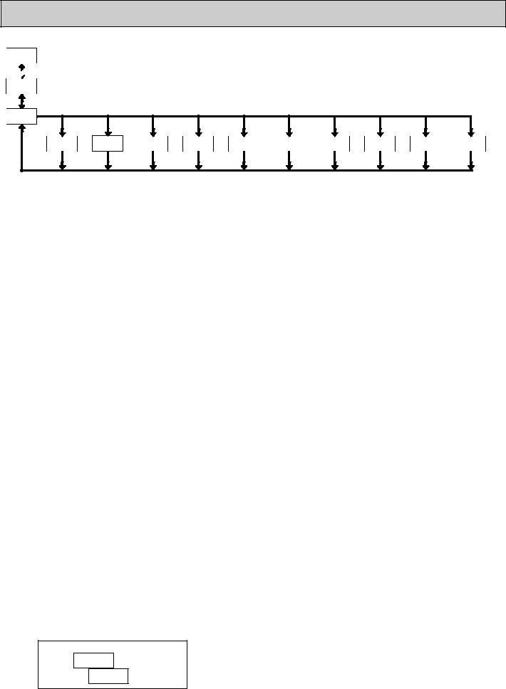
6.0 Programming the Meter
DISPLAY
MODE
PAR
OVERVIEW
PROGRAMMING MENU
NO
Pro
|
|
|
Display |
|
|
|
|
|
|
|
|
User Input/ |
Assignment/ |
|
|
|
|
|
|
Signal |
Signal |
Function |
Program |
Secondary |
Totalizer |
Setpoint* |
Serial* |
Analog* |
Factory |
Input A |
Input B |
Key |
Lock-out |
Function |
(Integrator) |
(Alarm) |
Communication |
Output |
Service |
Parameters |
Parameters |
Parameters |
Parameters |
Parameters |
Parameters |
Parameters |
Parameters |
Parameters |
Operations |
F1/F2 |
|
|
|
|
|
|
|
|
|
Keys |
|
|
|
|
|
|
|
|
|
PAR |
PAR |
PAR |
PAR |
PAR |
PAR |
PAR |
PAR |
PAR |
PAR |
1-InA |
1-Inb |
2-FNC |
3-LOC |
4-SEC |
5-tOt |
6-SPt |
7-SrL |
8-Out |
9-FCS |
* Only accessible with appropriate plug-in card.
DISPLAY MODE
The meter normally operates in the Display Mode. In this mode, the meter displays can be viewed consecutively by pressing the DSP key. The annunciators to the left of the display indicate which display is currently shown; A, B, or C. Each of these displays are programmable and can be locked from view through programming. (See Module 3.)
PROGRAMMING MODE
Two programming modes are available.
Full Programming Mode permits all parameters to be viewed and modified. Upon entering this mode, the front panel keys change to Programming Mode operations. This mode should not be entered while a process is running, since the meter functions and User Input response may not operate properly while in Full Programming Mode.
Quick Programming Mode permits only certain parameters to be viewed and/ or modified. When viewing parameters (SP1, etc), the front panel keys change to Programming Mode operations, and all meter functions continue to operate properly. Quick Programming Mode is configured in Module 3. The Display Intensity Level “ ” parameter is available in the Quick Programming Mode only when the security code is non-zero. For a description, see Module 9—Factory Service Operations. Throughout this document, Programming Mode (without Quick in front) always refers to “Full” Programming Mode.
PROGRAMMING TIPS
The Programming Menu is organized into ten modules (see above). These modules group together parameters that are related in function. It is recommended to begin programming with Module 1 and proceed through each module in sequence. Note that Modules 6 through 8 are only accessible when the appropriate plug-in option card is installed. If lost or confused while programming, press the DSP key to exit programming mode and start over. When programming is complete, it is recommended to record the meter settings on the Parameter Value Chart and lock-out parameter programming with a User Input or lock-out code. (See Modules 2 and 3 for lock-out details.)
FACTORY SETTINGS
Factory Settings may be completely restored in Module 9. This is a good starting point if encountering programming problems. Throughout the module description sections which follow, the factory setting for each parameter is shown below the parameter display. In addition, all factory settings are listed on the Parameter Value Chart following the programming section.
ALTERNATING SELECTION DISPLAY
In the module description sections which follow, the dual display with arrows appears for each programming parameter. This is used to illustrate the display alternating between the parameter (top display) and the parameter’s Factory Setting (bottom display). In most cases, selections or value ranges for the parameter will be listed on the right.
Indicates Program Mode Alternating Display
Parameter
Selection/Value
STEP BY STEP PROGRAMMING INSTRUCTIONS:
PROGRAMMING MODE ENTRY (PAR KEY)
The Programming Mode is entered by pressing the PAR key. If this mode is not accessible, then meter programming is locked by either a security code or a hardware lock. (See Modules 2 and 3 for programming lock-out details.)
MODULE ENTRY (ARROW & PAR KEYS)
Upon entering the Programming Mode, the display alternates between and the present module (initially ). The arrow keys (F1 and F2) are used to select the desired module, which is then entered by pressing the PAR key.
PARAMETER (MODULE) MENU (PAR KEY)
Each module has a separate parameter menu. These menus are shown at the start of each module description section which follows. The PAR key is pressed to advance to a particular parameter to be changed, without changing the programming of preceding parameters. After completing a module, the display will return to . From this point, programming may continue by selecting and entering additional modules. (See MODULE ENTRY above.)
PARAMETER SELECTION ENTRY (ARROW & PAR KEYS)
For each parameter, the display alternates between the parameter and the present selection or value for that parameter. For parameters which have a list of selections, the arrow keys (F1 and F2) are used to sequence through the list until the desired selection is displayed. Pressing the PAR key stores and activates the displayed selection, and also advances the meter to the next parameter.
NUMERICAL VALUE ENTRY (ARROW, RST & PAR KEYS)
For parameters which require a numerical value entry, the arrow keys can be used to increment or decrement the display to the desired value. When an arrow key is pressed and held, the display automatically scrolls up or scrolls down. The longer the key is held, the faster the display scrolls.
The RST key can be used in combination with the arrow keys to enter large numerical values. When the RST key is pressed along with an arrow key, the display scrolls by 1000’s. Pressing the PAR key stores and activates the displayed value, and also advances the meter to the next parameter.
PROGRAMMING MODE EXIT (DSP KEY or PAR KEY at )
The Programming Mode is exited by pressing the DSP key (from anywhere in the Programming Mode) or the PAR key (with displayed). This will commit any stored parameter changes to memory and return the meter to the Display Mode. If a parameter was just changed, the PAR key should be pressed to store the change before pressing the DSP key. (If power loss occurs before returning to the Display Mode, verify recent parameter changes.)
9
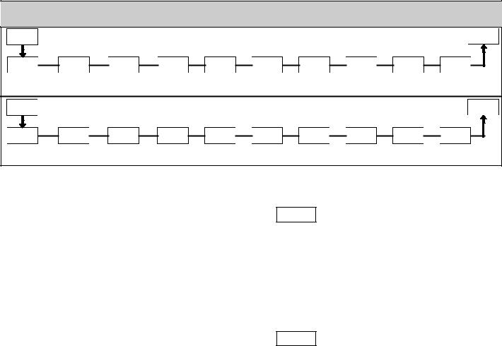
6.1 MODULE 1 - Signal Input Parameters
1-InA |
|
|
INPUT A PARAMETER MENU |
|
|
Pro |
|||
PAR |
|
|
|
|
|
|
|
|
|
rANgE |
rAtE |
dECPt |
round |
FILtr |
bANd |
PtS |
StYLE |
INP x |
dSP x |
Input |
Conversion |
Display |
Display |
Filter |
Filter |
Scaling |
Scaling |
Input x |
Display x |
Range |
Rate |
Decimal Point |
Rounding |
Setting |
Band |
Points |
Style |
Value |
Value |
1-Inb |
|
|
INPUT B PARAMETER MENU |
|
|
Pro |
|||
PAR |
|
|
|
|
|
||||
|
|
|
|
|
|
|
|
|
|
rANgE |
rAtE |
dECPt |
round |
FILtr |
bANd |
PtS |
StYLE |
INP x |
dSP x |
Input |
Conversion |
Display |
Display |
Filter |
Filter |
Scaling |
Scaling |
Input x |
Display x |
Range |
Rate |
Decimal Point |
Rounding |
Setting |
Band |
Points |
Style |
Value |
Value |
INPUT RANGE
|
SELECTION |
RANGE RESOLUTION |
|||
|
|
|
|
10.000 V |
|
|
|||||
|
20.000 mA |
||||
|
|
|
|||
|
|
|
|
±10.000 V - Square Root Extraction |
|
|
|
|
|
±20.000 mA - Square Root Extraction |
|
Select the input range that corresponds to the external signal. Before applying signal configure input jumper to match setting desired.
|
|
|
ADC CONVERSION RATE |
|
||
|
|
|
|
|
|
|
|
|
|
|
|
||
|
|
|
||||
|
|
|
|
|
||
Select the ADC conversion rate (conversions per second). The selection does not affect the display update rate, however it does affect setpoint and analog output response time. The default factory setting of 19.8 is recommended for most applications. Selecting a fast update rate may cause the display to appear very unstable.
|
|
|
DISPLAY DECIMAL POINT |
|
|
||
|
|
|
|
|
|
|
|
|
|
|
|
|
|
||
|
|
|
|
|
|
|
|
|
|
|
|
|
|
||
Select the decimal point location for the Input display. (The TOT display decimal point is a separate parameter.) This selection also affects , and parameters and setpoint values.
DISPLAY ROUNDING*
|
|
|
|
|
|
|
|
|
|
|
|
|
|
|
|
|
|
|||
|
|
|||||
|
|
|
|
|||
Rounding selections other than one, cause the Input Display to ‘round’ to the nearest rounding increment selected (ie. rounding of ‘5’ causes 121 to round to 120 and 124 to round to 125). Rounding starts at the least significant digit of the Input Display. Remaining parameter entries (scaling point values, setpoint values, etc.) are not automatically adjusted to this display rounding selection.
|
|
|
FILTER SETTING |
|
|
|
|
|
to seconds |
||
|
|
|
|
|
|
||
The input filter setting is a time constant expressed in tenths of a second. The filter settles to 99% of the final display value within approximately 3 time constants. This is an Adaptive Digital Filter which is designed to steady the Input Display reading. A value of ‘0’ disables filtering.
|
|
|
|
|
FILTER BAND* |
|
|
|
|
to display units |
The digital filter will adapt to variations in the input signal. When the variation exceeds the input filter band value, the digital filter disengages. When the variation becomes less than the band value, the filter engages again. This allows for a stable readout, but permits the display to settle rapidly after a large process change. The value of the band is in display units, independent of the Display Decimal Point position. A band setting of ‘0’ keeps the digital filter permanently engaged.
|
|
SCALING POINTS |
|
|
|
|
to |
Linear - Scaling Points (2)
For linear processes, only 2 scaling points are necessary. It is recommended that the 2 scaling points be at opposite ends of the input signal being applied. The points do not have to be the signal limits. Display scaling will be linear between and continue past the entered points up to the limits of the Input Signal Jumper position. Each scaling point has a coordinate-pair of Input Value ( ) and an associated desired Display Value ( ).
Square Root Extraction Input Range - Scaling Points (2)
The PAXDP can apply the square root function directly to the sensor signal by selecting the Square Root Extraction Input Range ( or ). When configured for Square Root Extraction, piecewise multipoint linearization is not required and only the first 2 scaling points are used. For proper operation the Display 1 ( ) value must be zero.
Nonlinear - Scaling Points (Greater than 2)
For non-linear processes, up to 16 scaling points may be used to provide a piece-wise linear approximation. (The greater the number of scaling points used, the greater the conformity accuracy.) The Input Display will be linear between scaling points that are sequential in program order. Each scaling point has a coordinate-pair of Input Value ( ) and an associated desired Display Value ( ). Data from tables or equations, or empirical data could be used to derive the required number of segments and data values for the coordinate pairs.
In the Crimson 2 (SFCRM2) software, several linearization equations are available. See the Accessories section for more information.
|
|
|
|
||
|
|
|
SCALING STYLE |
||
|
|
|
key-in data |
||
|
|
|
|
apply signal |
|
|
|
|
|||
|
|||||
|
|
||||
If Input Values and corresponding Display Values are known, the Key-in ( ) scaling style can be used. This allows scaling without the presence or changing of the input signal. If Input Values have to be derived from the actual input signal source or simulator, the Apply ( ) scaling style must be used.
* The decimal point position is dependent on the selection made in the “Display Decimal Point” parameter.
10
 Loading...