


Bulletin No. IFMR-J Drawing No. LP0341 Released 04/09
Tel +1 (717) 767-6511
Fax +1 (717) 764-0839 www.redlion.net
MODEL IFMR - DIN-RAIL SPEED SWITCH
SIMPLE ON-LINE TRIP FREQUENCY SETTING (USING ACTUAL
|
|
|
|
INPUT SIGNAL OR FREQUENCY GENERATOR) |
||
|
|
|
|
USER SETTABLE TRIP FREQUENCY FROM 0.1 Hz to 25 KHz |
||
|
|
|
|
OVER-SPEED, UNDER-SPEED, AND ZERO-SPEED DETECTION |
||
|
|
|
|
RELAY LATCHING, ALARM OVERRIDE, AND ALARM RESET |
||
|
|
|
|
FUNCTIONS |
||
|
|
|
|
PROGRAMMABLE INPUT CIRCUIT ACCEPTS OUTPUTS FROM |
||
|
|
|
|
A VARIETY OF SENSORS |
||
|
|
|
|
HYSTERESIS AND OFFSET FUNCTIONS AVAILABLE |
||
|
|
|
|
85 to 250 VAC and 9 to 32 VDC VERSIONS AVAILABLE |
||
|
|
|
|
INPUT AND RELAY STATUS INDICATION LED’S |
||
|
|
|
|
UL Recognized Component, |
||
|
|
|
|
File # E137808 |
||
|
|
|
|
|
|
|
|
|
|
|
|
|
|
DESCRIPTION |
The IFMR operates in one of six output modes, as selected by the user. The |
|||||
|
The Model IFMR accepts a frequency input, and controls a single relay |
programmable Minimum Response Time provides optimum response vs. input |
||||
(SPDT) based on the value of the input frequency. The Trip frequency can be |
filtering for any input frequency. The offset and hysteresis settings provide |
|||||
set to any value from 0.1 Hz to 25 KHz. The IFMR can be set to trip on |
flexible adjustment of the relay trip and release points. |
|||||
overspeed, or underspeed (including zero speed). Offset and hysteresis values |
The unit is equipped with a universal mounting foot for attachment to |
|||||
can be incorporated into the trip setting to eliminate output chatter. LED |
standard DIN style mounting rails, including top hat profile rail according to EN |
|||||
indicators for both the Input signal and the Relay status are provided. Two |
50 022 - 35 x 7.5 and 35 x 15, and G profile rail according to EN 50 035 - G32. |
|||||
separate input connections for external push-buttons are also provided. One |
SAFETY SUMMARY |
|||||
external input overrides the trip detection function, and holds the relay in the |
||||||
release state as long as the input is pulled to common. The other external input |
All safety related regulations, local codes and instructions that appear in the |
|||||
manual or on equipment must be observed to ensure personal safety and to |
||||||
clears a latched trip condition when pulled to common. |
||||||
prevent damage to either the instrument or equipment connected to it. If |
||||||
|
The IFMR utilizes a seven position DIP switch, a rotary switch, a push- |
|||||
|
equipment is used in a manner not specified by the manufacturer, the protection |
|||||
button and two indication LEDs to accomplish input circuit configuration, |
||||||
provided by the equipment may be impaired. |
||||||
operational parameter set-up, input signal, and relay status indication. The input |
||||||
WARNING: SPEED SWITCHES MUST NEVER BE USED AS |
||||||
circuitry is DIP switch selectable for a variety of sources. |
||||||
PRIMARY PROTECTION AGAINST HAZARDOUS OPERATING |
||||||
|
The indication LEDs are used during normal operation to display the input |
|||||
|
CONDITIONS. Machinery must first be made safe by inherent design, |
|||||
signal and relay status of the IFMR. These LEDs are also used to provide visual |
||||||
or the installation of guards, shields, or other devices to protect personnel in |
||||||
feedback to the user of the current parameter settings during parameter set-up. |
||||||
the event of a hazardous machine speed condition. The speed switch may be |
||||||
|
|
|
|
|||
|
|
|
|
installed to help prevent the machine from entering the unsafe speed. |
||
DIMENSIONS In inches (mm)
3.12 |
1.08 |
(79.2) |
(27.5) |
! |
ON |
.SRC |
LOGIC |
SINK |
MODE |
CFG2 |
CFG1 |
CFG0 |
.INSTRUCTIONS UP-SET FOR |
BULLETIN IFMR THE SEE |
|
|
|
|
9 |
0 |
1 |
|
|
|
|
|
|
|
|
8 |
|
2 |
|
|
|
|
|
|
|
7 |
|
|
3 |
|
|
|
|
|
|
|
|
6 |
5 |
4 |
|
|
|
|
|
|
|
|
|
|
|
|
|
||
|
|
|
.BULLETINIFMRTHESEE |
|
NOTMUSTDEVICETHISWARNING: PROTECTIONPRIMARYASUSEDBE OPERATINGHAZARDOUSAGAINST .CONDITIONSSPEED |
CONTROLSLIONRED .A.S.UINMADE.PAYORK, |
5W.550/60HZVAC250-85 |
|
COMM987 ~ |
OUT INPUT |
IN |
RESET |
ALARM |
AMP5 |
VACVAC |
120/240120/240 |
IFMR |
|||||||||
|
|
|
|
|
|
|
|
|
|
|
|
|
|
~ AC |
60mA |
+12V |
|
|
OVERRIDE |
ALARM |
AMP 5 |
|
|
|
|
|
|
|
|
|
|
|
|
|
|
|
|
|
|
10 |
|
|
|
|
4 |
|
|
|
|
|
|
||
|
|
|
|
|
|
|
|
|
|
|
|
|
|
|
|
|
1 |
|
|
|
|
|
||||
|
|
|
|
|
|
|
|
|
|
|
|
|
11 |
|
|
|
|
5 |
2 |
|
|
|
|
|
||
|
|
|
|
|
|
|
|
|
|
|
|
|
12 |
|
|
|
|
6 |
3 |
|
|
|
|
|
||
|
|
|
|
|
|
|
|
|
|
|
|
|
|
AC |
|
|
|
|
|
|
|
|
|
|
|
|
|
|
|
|
|
|
|
|
|
|
|
|
|
|
|
|
|
|
|
|
|
|
|
|
M1865G |
||
|
|
|
|
|
|
|
|
|
|
|
|
|
|
|
|
|
|
|
|
|
|
|
|
|
|
|
|
|
|
|
|
|
|
|
|
|
|
|
|
|
|
|
|
|
|
|
|
|
|
|
|
|
|
4.20 REF (106.7)
|
M1864G |
IN |
S |
|
T |
IFMR |
A |
T |
|
|
U |
OUT |
S |
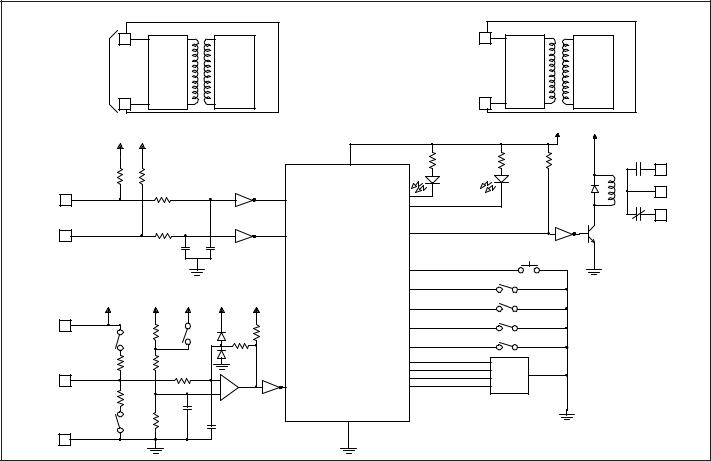
SPECIFICATIONS
1.POWER:
AC Powered Versions: 85 to 250 VAC; 48 to 62 Hz; 5.5 VA
DC Powered Versions: 9 to 32 VDC; 2.0 W
Power Up Current: Ip = 600 mA for 50 msec max.
2.SENSOR POWER: (AC version only) +12 VDC 25% @ 60 mA max.
3.OPERATING FREQUENCY RANGE: 0 Hz to 25 KHz
4.SIGNAL INPUT: DIP switch selectable to accept signals from a variety of sources, including switch contacts, outputs from CMOS or TTL circuits,
magnetic pickups, and all standard RLC sensors.
Current Sourcing: Internal 1 K pull-down resistor for sensors with current
sourcing output. (Max. sensor output current = 24 mA @ 24 V output.)
Current Sinking: Internal 3.9 K pull-up resistor for sensors with current sinking output. (Max. sensor current = 3 mA.)
Low Bias: Input trigger levers VIL = 0.25 V, VIH = 0.75 V; for increased sensitivity when used with magnetic pickups.
Hi Bias: Input trigger levels VIL = 2.5 V, VIH = 3.0 V; for logic level signals.
Max. Input Signal: ±90 V; 2.75 mA max. (with both Current Sourcing and Current Sinking resistors switched off).
CAUTION: Risk of Danger. Read complete instructions prior to installation and operation of the unit.
CAUTION: Risk of electric shock.
ORDERING INFORMATION
|
|
PART NUMBERS FOR AVAILABLE |
|
MODEL NO. |
DESCRIPTION |
SUPPLY VOLTAGES |
|
|
|
9 to 32 VDC |
85 to 250 VAC |
IFMR |
Speed Switch |
IFMR0036 |
IFMR0066 |
1
SPECIFICATIONS (Cont’d)
5.CONTROL INPUTS: Active low (VIL = 0.5 V max.) internally pulled up to 5
resistor (ISNK = 50 μA). Response Time = 1 msec.VDC through a 100 K
Alarm Reset: Unlatches the relay when pulled to common while the input frequency is in the release region.
Alarm Override: Causes the IFMR to unconditionally release the relay when pulled to common.
6.RELAY CONTACT OUTPUT: FORM “C” (SPDT) contacts max. rating. 5 A @ 120/240 VAC or 28 VDC (resistive load), 1/8 H.P. @ 120 VAC (inductive load). The operate time is 5 msec nominal and the release time is 3 msec nominal.
7.RELAY LIFE EXPECTANCY: 100,000 cycles at max. rating. (As load level decreases, life expectancy increases.)
8.ACCURACY: 0.1% of the trip frequency setting.
9.INPUT IMPEDANCE: 33 K min. with the sink and source DIP switches in the OFF positions. (See Block Diagram)
10.MINIMUM RESPONSE TIME: From 5 msec. +1 period to 10 sec. +1 period in ten steps (excluding relay operate time).
11.HYSTERESIS AND OFFSET: From 0.25% to 33.33% of Trip Frequency in nine steps. Hysteresis and/or Offset can also be set to 0 (Disabled).
12.INPUT AND POWER CONNECTIONS: Screw in terminal blocks
13.ISOLATION BREAKDOWN VOLTAGE (Dielectric Withstand):
2200 V between power & input, and power & output; 500 V between input
&output for 1 minute.
14.CERTIFICATIONS AND COMPLIANCES:
SAFETY
UL Recognized Component, File #E137808, UL508, CSA 22.2 No. 14 Recognized to U.S. and Canadian requirements under the Component Recognition Program of Underwriters Laboratories, Inc.
IECEE CB Scheme Test Certificate # UL1683A-176645/USA, CB Scheme Test Report # 97ME50135-042297
Issued by Underwriters Laboratories, Inc.
IEC 61010-1, EN 61010-1: Safety requirements for electrical equipment for measurement, control, and laboratory use, Part 1.
ELECTROMAGNETIC COMPATIBILITY |
|
|
|
Immunity to EN 50082-2 |
|
|
|
Electrostatic discharge |
EN 61000-4-2 |
Level 2; 4 Kv contact1 |
|
|
|
Level 3; 8 |
Kv air |
Electromagnetic RF fields |
EN 61000-4-3 |
Level 3; 10 V/m2 |
|
|
|
80 MHz - 1 GHz |
|
Fast transients (burst) |
EN 61000-4-4 |
Level 4; 2 |
Kv I/O |
|
|
Level 3; 2 |
Kv power |
RF conducted interference |
EN 61000-4-6 |
Level 3; 10 V/rms |
|
|
|
150 KHz - 80 MHz |
|
Power frequency magnetic fields EN 61000-4-8 |
Level 4; 30 A/m |
||
Emissions to EN 50081-2 |
|
|
|
RF interference |
EN 55011 |
Enclosure class A |
|
|
|
Power mains class A |
|
Notes:
1.This device was designed for installation in an enclosure. To avoid electrostatic discharge, precautions should be taken when the device is mounted outside an enclosure. When working in an enclosure (ex. making adjustments, setting switches, etc.) typical anti-static precautions should be observed before touching the unit.
2.For operation without loss of performance:
Unit is mounted on a rail in a metal enclosure (Buckeye SM7013-0 or equivalent) and I/O cables are routed in metal conduit connected to earth ground.
Refer to the EMC Installation Guidelines section of this bulletin for additional information.
15.ENVIRONMENTAL CONDITIONS: Operating Temperature: 0 to 50°C Storage Temperature: -40 to 80°C
Operating and Storage Humidity: 85% max. (non-condensing) from 0°C to 50°C.
Vibration according to IEC 68-2-6: Operational 5 to 150 Hz in X, Y, Z direction for 1.5 hours, 2 g’s.
Shock according to IEC 68-2-27: Operational 30 g’s (10 g relay), 11 msec in 3 directions.
Altitude: Up to 2000 meters
16.CONSTRUCTION: Case body is black, high impact plastic. Installation Category II, Pollution Degree 2
17.WEIGHT: 6 oz. (0.17 Kg)
|
|
|
|
|
|
|
BLOCK DIAGRAM |
|
|
|
|
|
|
|
|
|
AC VERSION |
|
|
|
+ |
10 |
DC VERSION |
|
|||
|
10 |
|
|
|
|
|
|
|
|
|
|||
|
AC |
|
|
|
|
|
|
|
|
|
|
|
|
|
POWER |
|
AC |
|
POWER |
|
|
|
9 to 32 VDC |
DC |
POWER |
|
|
|
85 to 250 |
|
SWITCHING |
SUPPLY |
|
|
|
SWITCHING |
SUPPLY |
|
|||
|
|
|
|
|
|
|
|
||||||
|
VAC |
|
CIRCUIT |
|
|
|
|
|
|
CIRCUIT |
|
|
|
|
12 |
|
|
|
|
|
|
- |
12 |
|
|
|
|
|
+5V |
+5V |
|
|
|
|
|
|
|
|
+5V |
+12V |
|
|
|
|
|
|
|
|
|
|
|
|
|
||
|
100K |
|
100K |
|
|
|
|
|
INPUT |
|
RELAY |
1 |
N.O. |
|
|
|
|
|
|
|
|
|
|
||||
|
|
|
|
|
|
|
|
|
(GREEN) |
|
(RED) |
|
|
ALARM |
|
|
10K |
|
|
|
ALARM |
INPUT LED |
|
|
|
2 |
COMM. |
4 |
|
|
|
|
|
|
|
|
|||||
OVERRIDE |
|
|
|
|
|
OVERRIDE |
RELAY LED |
|
|
|
|
|
|
|
|
|
|
|
|
|
|
|
|
|
3 |
N.C. |
|
|
|
|
|
|
|
|
|
|
|
|
|
||
ALARM |
|
|
10K |
|
|
|
ALARM |
RELAY |
|
|
|
|
|
6 |
|
|
|
|
|
|
|
|
|
|
|||
RESET |
|
|
|
|
|
RESET |
|
|
|
|
|
||
|
|
0.1µf |
|
0.1µf |
|
|
|
|
|
|
|
||
|
|
|
|
|
|
|
|
|
|
|
|
||
|
|
|
|
|
|
|
|
PUSH |
|
|
|
|
|
|
|
|
|
|
|
|
|
BUTTON |
|
|
|
|
|
|
|
|
|
|
|
|
|
INPUT |
|
S4 |
PUSH |
|
|
|
|
|
|
|
|
|
PROCESS |
|
MODE |
BUTTON |
|
|
|
(AC VERSION ONLY) |
|
|
|
|
|
|
|
S5 |
|
|
|
||
|
+12V |
|
+5V |
+5V |
+12V |
+12V |
CIRCUITRY |
|
|
|
|
|
|
SENSOR |
|
DIP |
CFG2 |
|
|
|
|||||||
|
|
|
|
|
|
|
|
|
|
|
|
||
|
|
|
|
|
|
|
SWITCH |
|
S6 |
|
|
|
|
SUPPLY |
|
|
|
|
|
|
|
|
|
|
|
||
|
|
|
|
|
|
|
INPUTS |
|
|
|
|
||
12 VDC |
7 |
|
54.9K |
S2 |
|
10K |
|
|
CFG1 |
|
|
|
|
S3 |
|
|
|
|
|
|
|
|
|||||
(60 mA) |
|
|
LOGIC |
392K |
|
|
|
|
S7 |
|
|
|
|
|
SINK |
|
|
|
|
|
|
|
|
||||
|
|
|
|
|
|
|
|
CFG0 |
|
|
|
||
|
|
3.9K |
8.06K |
|
|
|
|
|
|
|
|
|
|
INPUT |
|
|
|
33.2K |
|
|
|
BCD |
|
BCD |
|
|
|
SIGNAL |
8 |
|
|
|
+ |
|
INPUT |
INPUTS |
|
SWITCH |
|
|
|
|
|
|
|
- |
|
SIGNAL |
|
|
|
|
|
|
|
|
|
1K |
|
|
|
|
|
|
|
|
|
||
|
|
|
0.1µf |
|
|
|
|
|
|
|
|
||
|
|
|
|
|
|
|
|
|
|
|
|
|
|
|
|
S1 |
10.0K |
|
|
|
|
|
|
|
|
|
|
|
|
SRC |
|
470pf |
|
|
|
|
|
|
|
|
|
INPUT |
|
|
|
|
|
|
|
|
|
|
|
|
|
9 |
|
|
|
|
|
|
|
|
|
|
|
|
|
COMMON |
|
|
|
|
|
|
|
|
|
|
|
|
|
|
|
|
|
|
|
|
|
|
|
|
|
|
|
|
|
|
|
|
|
|
|
2 |
|
|
|
|
|
OVERVIEW
The Model IFMR continuously monitors the input signal and controls an output relay based on the frequency of the input signal, the chosen Operation Mode (Underspeed or Overspeed), and the Trip and Release points the user has selected. The green Input LED blinks at the rate of the input frequency. At about 100 Hz, the Input LED will appear to be solid on. At very low frequencies, the Input LED blinks slowly and may also appear to be solid on. A loss of signal may also cause the Input LED to remain on, depending on the DIP switch setup. In this case, the red Relay LED also turns on. The IFMR indicates the status of the relay with the Relay LED (Red). Whenever the relay is in the Trip state, the IFMR turns ON the Relay LED. In the Release state, the Relay LED is OFF.
For Overspeed detection, when the input frequency (averaged over the Minimum Response Time) exceeds the Trip point, the IFMR trips the relay. With the relay in the Trip condition, the input frequency must fall below the Release point for the relay to release.
For Underspeed detection, the relay trips when the input frequency (averaged over the Minimum Response Time) falls below the Trip point. The relay releases only after the input frequency has exceeded the Release point. Two of the Underspeed operating modes allow the machine or system that supplies the input signal to reach normal operating speed before the IFMR responds to an Underspeed condition. For Zero Speed applications, bear in mind that Zero Speed detection and Underspeed detection are identical.
The Minimum Response Time parameter sets the minimum update time of the output. The actual response time is the Minimum Response Time plus up to one full period of the input signal. The IFMR counts the negative edges occurring during the update time period, and computes the average frequency value for that time. This action filters out any high frequency jitter that may be present in the input signal. The longer the Minimum Response Time, the more filtering occurs.
The Offset value is added to the Trip Frequency to determine the Trip Point for Overspeed operation. For Underspeed operation the Trip point becomes the Trip Frequency minus the Offset value.
If No Hysteresis has been selected, the Trip and Release points are identical, which can lead to cycling or “chattering” of the relay at input frequencies hovering around the Trip point. If Hysteresis is selected, the Release point is set to the Trip point (including Offset) minus the Hysteresis value for Overspeed detection. For Underspeed detection, the Release point is set to the Trip point (including Offset) plus the Hysteresis value.
Two input pins (Alarm Override and Alarm Reset) are provided for the optional connection of push-buttons. The Alarm Override pin causes the IFMR to unconditionally Release the relay, regardless of the input frequency, or the state of the relay, when pulled to common. When the Alarm Override pin is released from common, the operation of the IFMR returns to normal, and the status of the relay is updated based on the input frequency.
The Alarm Reset pin is only active when the IFMR is in one of the Latch operation modes. With the Latch function selected, the relay “latches” into the Trip state whenever a Trip condition is detected. The relay remains latched until the Alarm Reset pin is pulled to common while the input frequency is in the Release region. The Alarm Reset pin is ignored while the input frequency is in the Trip region.
EMC INSTALLATION GUIDELINES
Although this unit is designed with a high degree of immunity to ElectroMagnetic Interference (EMI), proper installation and wiring methods must be followed to ensure compatibility in each application. The type of the electrical noise, source or coupling method into the unit may be different for various installations. The unit becomes more immune to EMI with fewer I/O connections. Cable length, routing, and shield termination are very important and can mean the difference between a successful installation or a troublesome installation.
Listed below are some EMC guidelines for successful installation in an industrial environment.
1.Use shielded (screened) cables for all Signal and Control inputs. The shield (screen) pigtail connection should be made as short as possible. The connection point for the shield depends somewhat upon the application.
Listed below are the recommended methods of connecting the shield, in order of their effectiveness.
a.Connect the shield only at the rail where the unit is mounted to earth ground (protective earth).
b.Connect the shield to earth ground at both ends of the cable, usually when the noise source frequency is above 1 MHz.
c.Connect the shield to common of the unit and leave the other end of the shield unconnected and insulated from earth ground.
2.Never run Signal or Control cables in the same conduit or raceway with AC power lines, conductors feeding motors, solenoids, SCR controls, and heaters, etc. The cables should be run in metal conduit that is properly grounded. This is especially useful in applications where cable runs are long and portable two-way radios are used in close proximity or if the installation is near a commercial radio transmitter.
3.Signal or Control cables within an enclosure should be routed as far away as possible from contactors, control relays, transformers, and other noisy components.
4.In very electrically noisy environments, the use of external EMI suppression devices, such as ferrite suppression cores, is effective. Install them on Signal and Control cables as close to the unit as possible. Loop the cable through the core several times or use multiple cores on each cable for additional protection. Install line filters on the power input cable to the unit to suppress power line interference. Install them near the power entry point of the enclosure. The following EMI suppression devices (or equivalent) are recommended:
Ferrite Suppression Cores for signal and control cables: Fair-Rite # 0443167251 (RLC #FCOR0000) TDK # ZCAT3035-1330A
Steward #28B2029-0A0 Line Filters for input power cables:
Schaffner # FN610-1/07 (RLC #LFIL0000) Schaffner # FN670-1.8/07
Corcom #1VR3
Note: Reference manufacturer’s instructions when installing a line filter.
5.Long cable runs are more susceptible to EMI pickup than short cable runs. Therefore, keep cable runs as short as possible.
WIRING CONNECTIONS
All conductors should meet voltage and current ratings for each terminal. Also cabling should conform to appropriate standards of good installation, local codes and regulations. It is recommended that power supplied to the unit (AC or DC) be protected by a fuse or circuit breaker.
POWER AND OUTPUT CONNECTIONS
AC Power
Primary power is connected to terminals 10 and 12 (labeled AC). For best results, the AC Power should be relatively “clean” and within the specified variation limits. Drawing power from heavily loaded circuits or from circuits that also power loads that cycle on and off, should be avoided.
DC Power
The DC power is connected to Terminals 10 and 12. The DC plus (+) is connected to Terminal 10 and the minus (-) is connected to Terminal 12. It is recommended that separate supplies be used for sensor power and unit power. Using the same supply for both will negate isolation between input and power.
Output Wiring
Terminals 1, 2, and 3 are used to connect to the relay output. Terminal 1 is the normally open contact. Terminal 3 is the normally closed contact, and Terminal 2 is the output relay common.
120/240 |
|
|
|
120/240 |
|
VAC |
|
|
|
VAC |
|
5 AMP |
1 |
2 |
3 |
5 AMP |
|
|
|
||||
ALARM |
4 |
5 |
6 |
ALARM |
|
OVERRIDE |
RESET |
||||
|
|
|
|||
|
|
IN |
|
|
|
|
|
OUT |
|
INPUT |
|
+12V |
|
|
|
||
7 |
8 |
9 |
COMM |
||
60mA |
|||||
|
|
|
|
||
~ |
10 |
11 |
12 |
~ |
|
AC |
|
|
|
AC |
3
 Loading...