

Page 1

ST60 Club
House Wind
Instrument
Owner’s
Handbook
Document number: 81148_4
Date: 1 April 2004
Page 2

Raymarine, ST60 and SeaTalk are trademarks of Raymarine Limited
© Handbook cont ents c opyright Raymarine Limited 2004
Page 3
Preface i
Preface
Important information
Safety notices
WARNING: Product installation & operation
This equipment must be installed and operated in accordance
with the Raymarine instructions provided. Failure to do so could
result in personal injury, damage to your property and/or poor
product performance.
WARNING: Electrical safety
Make sure you have switched off the power supply before you
start installing this product.
WARNING:
The ST60 Club House Wind is intended only for fixed, shore-based
use and is not suitable for use on boats.
EMC conformance
All Raymarine equipment and accessories are designed to the best industry
standards for use in the recreational marine environment.
The design and manufacture of Raymarine equipment and accessori es conform to
the appropriate Electromagnetic Compatibility (EMC) standards, but correct
installation is required to ensure that performance is not compromised.
Handbook information
To the best of our knowledge, the information in this handbook was correct when
it went to press. However, Raymarine cannot accept liability for any inaccuracies
or omissions it may contain.
In addition, our policy of continuous product improvement may change
specifications without n otice. Therefore, Raymarine cannot ac cept liability for any
differences between the product and the handbook.
Page 4

ii ST60 Club House Wind Instrument Owner’s Handbook
Page 5

Preface iii
Contents
Preface ......................................................................................................................i
Important information ..................................................................................... i
Safety notices .......................................................................................... i
EMC conformance ................................................................................... i
Handbook information ............................................................................ i
Contents................................................................................................... iii
Introduction .................................................................................................... v
Mounting options ........................................................................................... v
Parts supplied ................................................................................................ vi
Chapter 1: Operation & Maintenance ................................................................1
1.1 Getting started ....................................................................................... 1
Calibration requirements ....................................................................... 1
1.2 Normal operation ................................................................................... 1
Pointer ................................................................................................... 1
Digital display ........................................................................................ 1
Beaufort wind speed ........................................................................ 1
Maximum wind speed ..................................................................... 2
Wind speed alarms .......................................................................... 2
Switching alarms on and off ...................................................... 3
Setting alarm thresholds ............................................................ 3
Display illumination ............................................................................... 3
1.3 Maintenance .......................................................................................... 3
Servicing and safety ............................................................................... 3
Instrument ............................................................................................. 4
Transducer ............................................................................................. 4
Cabling ................................................................................................... 4
1.4 Troubleshooting ..................................................................................... 4
Preliminary procedures .......................................................................... 4
Fixing faults ............................................................................................ 5
Technical support ................................................................................... 5
World wide web ............................................................................... 5
Telephone help line .......................................................................... 5
Help us to help you ........................................................................... 5
Chapter 2: Installation .........................................................................................7
2.1 Planning your installation ...................................................................... 7
Site requirements ................................................................................... 7
Wind Vane ....................................................................................... 7
Instrument ....................................................................................... 8
EMC installation guidelines .................................................................... 9
Suppression ferrites ......................................................................... 9
Page 6

iv ST60 Club House Wind Instrument Owner’s Handbook
Connections to other equipment .................................................... 10
2.2 Installation procedure .......................................................................... 10
Unpacking ............................................................................................10
Fitting the instruments ......................................................................... 10
Surface mounting ...........................................................................11
Flush Mounting ..............................................................................12
Fitting the low-profile bezel ...................................................... 12
Flush mounting procedure ....................................................... 13
Bracket Mounting Kit .....................................................................14
Connections at the instrument ............................................................. 14
Power supply connections ..............................................................15
Linearization ......................................................................................... 16
Fitting the Wind Vane ...........................................................................16
Running transducer cable ...............................................................18
Chapter 3: Calibration ........................................................................................ 21
3.1 Introduction .......................................................................................... 21
EMC conformance ................................................................................21
3.2 User calibration .................................................................................... 21
Leaving User calibration .......................................................................22
3.3 Intermediate calibration .......................................................................22
3.4 Dealer calibration .................................................................................23
Response settings .................................................................................23
Wind speed ...........................................................................................23
Boat show mode ................................................................................... 25
Factory defaults ....................................................................................25
Leaving Dealer calibration .................................................................... 25
Page 7
Preface v
Introduction
Thank you for purchasing a Raymarine prod uct. We are sure your ST60 instrument
will give you many years of trouble-free operation.
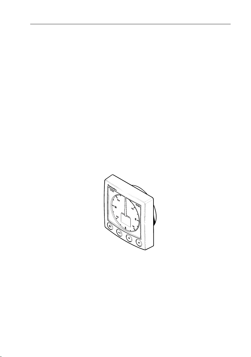
This handbook describes how to install and use the Raymarine ST60 Club House
Wind instrument, which is intended for use ashore (e.g. in clubhouses or homes)
to show local wind conditions. The instrument is constructed in a rugged weather
proofed case and uses a sensitive and stable, combined analog and digital
display, to display the wind information.
The ST60 Club House Wind instrument is not suitable for use on
boats.
The ST60 Club House Wind instrument gives:
• Wind speed.
• Wind Angle.
• Maximum wind speed.
The ST60 Club House Wind instrument also gives high and low wind speed alarm
indications.
Mounting options
If you do not want to surface mount your ST60 instrument, options are available
for:
• Flush mounting. If you have ordered the flush mounting option a low-profile
bezel and four fixing screws are also provided.
• Bracket mounting.
D4514-2
Page 8
vi ST60 Club House Wind Instrument Owner’s Handbook
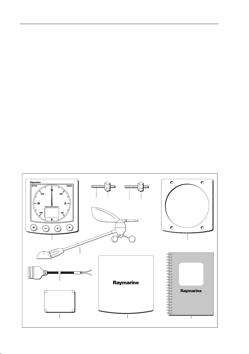
Parts supplied
Unpack your ST60 instrument and check that the following items are present:
• Item 1, ST60 Club House Wind instrument, fitted with standard bezel for surface mounting.
• Item 2, Fixing studs (2).
• Item 3, Thumb nuts (2).
• Item 4, Gasket.
• Item 5, Wind Vane.
• Item 6, Power cable.
• Item 7, Instrument Cover.
• Item 8, Junction Box.
• Item 9, Owner’s Handbook. A Warranty document and fitting templates are
included in this Handbook.
Spare spade terminals are also provided, to re-terminate transducer cables if they
have to be cut to facilitate installation.
Note:
The above packing list is for an ST60 Wind system.
32
1
5
6
8
32
4
ST60 Club
House Wind
Instrument
Owner's
Handbook
7 9
D4503-3
Page 9

Chapter 1: Operation & Maintenance 1
Chapter 1: Operation & Maintenance
1.1 Getting started
This handbook describes how to operate, maintain and install the Raymarine
ST60 Club House Wind instrument. This instrument shows the wind speed and
direction.
CAUTION: Calibration requirement
The ST60 Club House Wind instrument is calibrated to factory
(default) settings when first supplied. To ensure optimum
performance, this product must be calibrated before use. Do NOT
use the product until it has been calibrated using the procedures
in
Chapter 3, Calibration
Calibration requirements
Your ST60 instrument is calibrated to factory (default) settings when first installed
and must therefore be calibrated before use, in accordance with th e procedures in
Chapter 3, Calibration
1.2 Normal operation
.
.
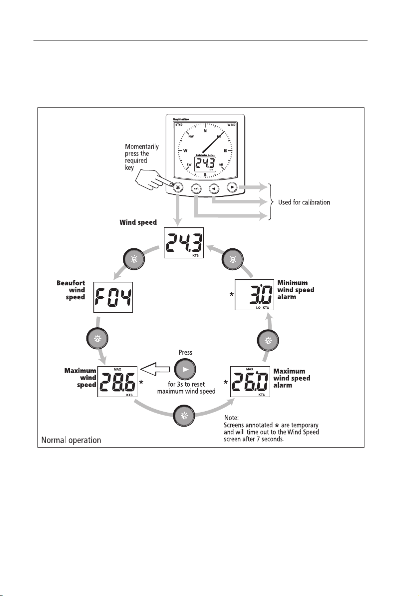
The information on the ST60 Club House Wind instrument is presented by a
pointer and a digital display.
Pointer
The pointer shows the wind direction.
Digital display
The digital display normally shows the wind speed in either knots or meters per
second. You can use the key to select other information (see the
operation
• Beaufort wind speed.
• Maximum wind speed.
• Maximum wind speed alarm.
• Minimum wind speed alarm.
flow chart), displayed as follows:
Beaufort wind speed
The appropriate Beaufort wind ‘force’ number, up to F12.
Normal
Page 10
2 ST60 Club House Wind Instrument Owner’s Handbook
Maximum wind speed
The maximum wind speed is reset at power up and can also be reset manually by
pressing the
> key for 3 seconds.
D4504-2
Wind speed alarms
An alarm condition occurs when the wind speed either exceeds the maximum
wind speed alarm threshold or falls below the minimum wind speed alarm
threshold. An alarm condition is indicated by a flashing alarm icon on the digital
display and an audible alarm at the instrument.
Pressing any key will cancel an alarm.
Page 11

Chapter 1: Operation & Maintenance 3
Switching alarms on and off
Use the key to select either the maximum or minimum wind speed alarm
screen as required, then press the
the alarm either on (i.e. so the alarm threshold value is displayed) or OFF, as
required.
Setting alarm thresholds
To set a wind speed alarm threshold:
1. Use the key to select either the maximum or minimum wind speed alarm
screen, as required.
2. Momentarily press both the
(indicated by the displayed value flashing).
3. Press either the
4. Momentarily press both the
(indicated by the displayed value flashing).
< key or the > key to set the required wind speed.
> key for approximately one-second, to toggle
< and > keys to enter the threshold adjust mode
< and > keys to leave the threshold adjust mode
Display illumination
When the instrument is first powered up, the display illumination is set to its
lowest (courtesy) level, to facilitate initial access to the keys.
To adjust the level of display illumination:
1. Hold down the key for approximately one second, to enter the illumination-adjust mode.
2. There are four preset illumination levels. Momentarily press the key to
cycle through these levels until you reach the level you want.
3. Press any other key to leave the illumination-adjust mode.
Note:
The digital display will return to normal operation 7 seconds after the last key press.
1.3 Maintenance
Servicing and safety
• Raymarine equipment should be serviced only by authorized Raymarine service technicians. They will ensure that service procedures and replacement
parts used will not affect performance. There are no user serviceable parts in
any Raymarine product.
• Some products generate high voltages, so never handle the cables/connectors when power is being supplied to the equipment.
Page 12

4 ST60 Club House Wind Instrument Owner’s Handbook
• When powered up, all electrical equipment produces electromagnetic fields.
These can cause adjacent pieces of electrical equipment to interact with one
another, with a consequent adverse effect on operation. In order to minimize
these effects and enable you to get the best possible performance from your
Raymarine equipment, guidelines are given in the installation instructions, to
enable you to ensure minimum interaction between different items of equipment, i.e. ensure optimum Electromagnetic Compatibility (EMC).
• Always report any EMC-related problem to your nearest Raymarine dealer.
We use such information to improve our quality standards.
• In some installations, it may not be possible to prevent the equipment from
being affected by external influences. In general this will not damage the
equipment but it can lead to spurious resetting action, or momentarily may
result in faulty operation.
Instrument
Certain atmospheric conditions may cause condensation to form on the
instrument window. This will not harm the instrument and can be cleared by
increasing the illumination setting to Level 3.
Periodically clean your ST60 instrument with a soft damp cloth. Do NOT use
chemical and abrasive materials to clean the instrument.
Transducer
If the windvane is removed from its mounting block for any reason, fit the
blanking cover (supplied) to the windvane mounting block connector.
Cabling
Examine all cables for chafing or other damage to the outer shield and, where
necessary, replace and re-secure.
1.4 Troubleshooting
Preliminary procedures
Changes in the electronic environment may adversely affect the operation of your
ST60 equipment. If a you appear to have a problem, first ensure that the EMC
requirements (see
further investigating the problem.
Chapter 2, Installation & Calibration
) are still being met before
Page 13

Chapter 1: Operation & Maintenance 5
Fixing faults
All Raymarine products are subjected to comprehensive test and quality
assurance programmes prior to packing and shipping. However, if the instrument
display is blank due to an apparent fault, check:
• The power supply.
• The security of cables and connectors.
• The fuse or circuit breaker.
Technical support
Raymarine provides a comprehensive customer support service, on the world
wide web and by telephone help line. Please use either of these facilities if you are
unable to rectify a problem.
World wide web
Please visit the Customer Support area of our web site at:
• www.raymarine.com
As well as providing a comprehensive Frequently Asked Questions section and
servicing information, the web site gives e-mail access to the Raymarine Technical
Support Department and a details of the locations of Raymarine agents,
worldwide.
Telephone help line
If you do not have access to the world wide web, please call our help line.
In the USA, call:
• +1 800 539 5539, extension 2444 or
• +1 603 881 5200 extension 2444
In the UK, Europe the Middle East or the Far East, call:
• +44 (0) 23 9271 4713 (voice)
• +44 (0) 23 9266 1228 (fax)
Help us to help you
When requesting service, please quote the following product information:
• Equipment type.
• Model number.
• Serial number.
• Software issue number.
The Software issue number can be ascertained by means of the Intermediate
Calibration facility, see
Chapter 3, Calibration
.
Page 14

6 ST60 Club House Wind Instrument Owner’s Handbook
Page 15

Chapter 2: Installation 7
Chapter 2: Installation
This chapter describes how to install and calibrate the ST60 Club House Wind
instrument, and associated Wind Vane transducer.
The transducer is connected to the rear of the instrument.
For advice, or further information regarding the installation of this equipment,
please contact the Raymarine Product Support Department or your own National
Distributor.
2.1 Planning your installation
Before starting the installation, spend some time considering the best positions
for both transducer and instrument, such that the
installation guidelines
are satisfied.
Site requirements
Wind Vane
The Wind Vane has a cable connected, and is supplied with a junction box and a
set of spade terminals.
The location for the Wind Vane must:
• Allow reasonable access for installation and servicing.
• Be as high as possible and away from any object which may shield the Wind
Vane or otherwise disturb the air flow.
• Provide a horizontal mounting surface. If a surface (e.g. mast top) is otherwise
suitable but not horizontal, make up a suitable wedged packing piece to provide the necessary horizontal surface.
Site requirements
and the
EMC
2.7 in (68 mm)
21.2 in (538.5 mm)
10.7 in (272 mm)
1.5 in (38 mm)
9.76 in (248 mm)
D6495-2
Page 16

8 ST60 Club House Wind Instrument Owner’s Handbook
There must also be a viable route for the transducer cable to be routed to the
instrument.
Note:
As you will need to manually rotate the Wine Vane as part of the linearization pro-
cedure, do not actually fit it in position yet.
Instrument
CAUTION:
The presence of moisture at the rear of the instrument could cause
damage either by entering the instrument through the breathing
hole or by coming into contact with the electrical connectors.
Each instrument must be positioned where:
• It is protected against physical damage.
• It is at least 20 in (500 mm) from radio receiving equipment.
• There is reasonable rear access for installation and servicing.
With standard
bezel
diameter
3.54 in (90 mm)
4.53 in (115 mm)
4.33 in (110 mm)
With low
profile bezel
4.85 in (123 mm)
ST60 instrument dimensions
0.25 in
(6.2 mm)
0.95 in
(24 mm)
1.4 in
(35 mm)
0.6 in
(15 mm)
diameter
3.54 in (90 mm)
4.85 in (123 mm)
D5785-4
Page 17

Chapter 2: Installation 9
EMC installation guidelines
All Raymarine equipment and accessories are designed to the best industry
standards for use in the recreational marine environment.
Their design and manufacture conforms to the appropriate Electromagnetic
Compatibility (EMC) standards, but correct installation is required to ensure that
performance is not compromised. Although every effort has been taken to ensure
that they will perform under all conditions, it is important to understand what
factors could affect the operation of the product.
The guidelines given here descri be the conditions for optimum EMC performa nce,
b ut it i s r ec o gn iz e d t ha t it ma y n ot b e p os si bl e to me e t a ll o f t he s e c on di ti o ns in a ll
situations. To ensure the best possible conditions for EMC performance within the
constraints imposed by any location, always ensure the maximum separation
possible between different items of electrical equipment.
For optimum EMC performance, it is recommended that wherever possible:
• Raymarine equipment and cables connected to it are:
• At least 3 ft (1 m) from any equipment transmitting or cables carrying
radio signals e.g. VHF radios, cables and antennas. In the case of SSB
radios, the distance should be increased to 7 ft (2 m).
• More than 7 ft (2 m) from the path of a radar beam. A radar beam can nor-
mally be assumed to spread 20 degrees above and below the radiating
element.
• The equipment is supplied from a separate battery from that used for engine
start. Voltage drops below 10 V in the power supply to our products, and
starter motor transients, can cause the equipment to reset. This will not damage the equipment, but may cause the loss of some information and may
change the operating mode.
• Raymarine specified cables are used. Cutting and rejoining these cables can
compromise EMC performance and must be avoided unless doing so is
detailed in the installation manual.
• If a suppression ferrite is attached to a cable, this ferrite should not be
removed. If the ferrite needs to be removed during installation it must be reassembled in the same position.
Suppression ferrites
The following illustration shows typical cable suppression ferrites used with
Raymarine equipment. Always use the ferrites supplied by Raymarine.
Page 18

10 ST60 Club House Wind Instrument Owner’s Handbook
D3548-6
Connections to other equipment
If your Raymarine equipment is to be connected to other equipment using a cable
not supplied by Raymarine, a suppression ferrite MUST always be attached to the
cable near the Raymarine unit.
2.2 Installation procedure
As it is not possible to describe procedures for all possible installation scenarios,
the procedures given here describe the broad requirements for installing a Wind
Vane and ST60 Club House Wind instrument. Adapt these procedures as
appropriate, to suit your individual requirement.
CAUTION:
Where it is necessary to cut holes (e.g. for cable routing and
instrument mounting), ensure that these will not cause a hazard
by weakening critical parts of any structure.
Unpacking
Unpack your ST60 instrument and check that the items described in the
are present.
Each ST60 instrument is supplied with a standard bezel for surface mounting.
Optional mounting kits are available for flush mounting and bracket mounting
the instrument. If you have ordered the flush mounting option a low-profile bezel
and four fixing screws are also provided.
Fitting the instruments
The ST60 Club House Wind instrument can be installed using one of a number of
different mounting options:
• Surface mounting. Gives a profile of approximately 0.95 in (24 mm).
• Flush mounting. Gives a profile of approximately 0.25 in (6 mm).
• Bracket mounting.
Preface
Page 19

Chapter 2: Installation 11
ST60 instruments can also be mounted behind a suitably prepared panel, so that
just the instrument dial and keys are visible.
Surface mounting
To surface mount your ST60 instrument (see the
1. Ensure that:
• The selected location is clean, smooth and flat.
• There is sufficient space behind the location to accommodate the rear of
the instrument and connectors.
2. Apply the surface mount template (supplied at the rear of this handbook) to
the selected location and mark the centers for the fixing studs (1) and the
aperture (3) that will take the rear casing of the instrument.
3. Drill out the two 0.2 in (5 mm) fixing stud clearance holes (2).
4. Cut out the clearance hole (3) then remove the template.
5. Peel off the protective sheet from the self-adhesive gasket (4) then stick the
gasket into position on the rear of the instrument.
6. Screw the two fixing studs into the threaded sockets on the rear of the instrument.
7. Mount the assembled instrument, studs, bezel and gasket into the panel.
Secure from behind with the thumb nuts (5).
Surface mounting
illustration):
Surface mounting
11223455
D4507-2
Page 20

12 ST60 Club House Wind Instrument Owner’s Handbook
Flush Mounting
The Flush Mounting Kit uses a low-profile bezel to reduce the fitted profile of the
instrument, to approximately 0.25 in (6 mm) above the panel fascia.
Fitting the low-profile bezel
In order to flush-mount your ST60 instrument, you must first replace the standard
bezel with the low-profile bezel as follows:
1. Hold the instrument in both hands with the display towards you.
D4537-2
2. Using both thumbs, gently press an upper corner of the instrument from the
bezel, then remove the bezel from the instrument. Retain the rubber keypad
which is released when the bezel is removed.
3. Place the instrument face upwards on a flat surface and place the rubber keypad (7) in position around the display window (i.e. so that each key outline is
located over its associated key on the instrument).
4. Snap the low-profile bezel (8) in position over the instrument, so that the rubber keys are correctly located in the holes on the bezel.
CAUTION:
It is essential that only screws of the correct size are used to
secure the instrument to the bezel. Failure to observe this caution
could result in damage to both the instrument and the bezel.
5. Using the four, self-tapping screws (9) provided, secure the instrument and
bezel together. Fit the screws from the rear of the instrument and tighten
them sufficiently to secure the instrument and bezel together. DO NOT OVERTIGHTEN.
Page 21

Chapter 2: Installation 13
789
Fitting the low profile bezel
D4509-2
Flush mounting procedure
Flush mount your instrument (see the
1. Assemble the ST60 instrument and low-profile bezel as described under
ting the low-profile bezel
.
Flush mounting
illustration) as follows:
Fit-
2. Ensure that:
• The panel on which you intend to mount the instrument is between
0.12 in (3 mm) and 0.78 in (20 mm) thickness.
• The selected location is clean, smooth and flat.
• There is sufficient space behind the location to accommodate the rear of
the instrument and connectors.
3. Apply the flush mount template (supplied at the rear of this handbook) to the
selected location and mark out the aperture into which the assembled instrument and bezel will sit.
4. Cut out the aperture (3) for the assembled instrument and bezel and remove
the template.
5. Peel off the protective sheet from the self-adhesive gasket (4) then stick the
gasket into position on the rear of the bezel.
Page 22

14 ST60 Club House Wind Instrument Owner’s Handbook
Flush mounting
113
4
556
D4510-3
6. Screw the two fixing studs (1) into the threaded sockets on the rear of the
instrument.
7. Mount the assembled instrument, studs, bezel and gasket into the panel.
8. Locate the flush mount bracket (6) onto the fixing studs and secure the assembly to the panel with the thumb-nuts (5).
Bracket Mounting Kit
A Control Unit Mounting Bracket (Part No. E25009) enables you to mount your
ST60 instrument in locations where other forms of mounting are impractical.
Although this provides a useful alternative method for securing your instrument,
it is only suitable for use in positions where the instrument will not be exposed to
water.
To bracket mount your ST60 instrument, do so in accordance with the Control Unit
Mounting Bracket Instruction Sheet.
Connections at the instrument
The connections to the ST60 Club House Wind instrument are shown in the
following illustration.
Page 23

Chapter 2: Installation 15
Power supply cable
Screen
Yellow
Blue
Green
Cable from Wind Vane
Red
Connections to ST60 Club House Wind instrument
D4511-2
Power supply connections
The ST60 Club House Wind instrument requires a 12 V dc power supply capable of
providing at least 2 A and protected by a 0.5 A fuse.
Power cables are available in 2 m and 9 m lengths.
To fit a power cable:
1. Ensure the intended power source is switched off.
2. Run the power cable from the instrument to a suitable 12 V dc power source.
5 A circuit breaker
12 V dc
supply
Power connections for stand-alone instrument
If the cable has not already been trimmed at the power supply end:
i. Cut the cable to length and trim back an appropriate amount of the outer
sheath.
ii. Cut back and insulate the yellow wire.
3. Connect the screen to the power supply 0 V terminal.
Red
Screen
D4310-5
Page 24

16 ST60 Club House Wind Instrument Owner’s Handbook
4. Connect the red wire via a 3 A circuit breaker to the power supply +12 V terminal.
5. Insert the power cable connector into one of the SeaTalk connectors at the
rear of the instrument.
Linearization
This procedure ensures that the sensors in the Wind Vane are correctly calibrated
to record rotation of the Wind Vane, then compensates for any small errors which
may exist in the alignment of the wind transducer. As this procedure necessitates
manual rotation of the Wind Vane, carry out this procedure, before fitting the
Wind Vane in its operational location.
To carry out the linearization and alignment procedure:
1. Referring to the
Connections to ST60 Club House Wind instrument
illustra-
tion, temporarily connect the Wind Vane to the instrument.
2. Power-up the ST60 Club House Wind instrument.
3. Manually rotate the vane for two rotations, so that each rotation takes
approximately 15 seconds. This procedure automatically linearizes the windvane. A successful linearization is indicated by the digital display flashing and
the buzzer sounding three beeps.
Fitting the Wind Vane
Note:
Do NOT remove the connec tor cap from the wind vane base connector, until you are
ready to fit the wind vane arm.
The wind vane base must be horizontal. If necessary, make up a suitable packing
piece to provide a horizontal mounting surface.
Packing piece, if required
D6868-2
You can fit your wind vane so the cable leaves the wind vane base either from the
rear (option A), or from underneath (option B), as in the following
cable options
illustration.
Wind vane
Page 25

Chapter 2: Installation 17
Option A Option B
Mounting
surface
View from underneath showing
arrangement of cable
Wind vane cable options
Cutaway view, showing
arrangement of cable
D6870-3
A wind vane is typically mounted on a mast top, as follows:
1. Mark the mounting surface for drilling. The recommended method for doing
this depends on which cable option you intend to use:
• For cable option A, place the wind vane base in the intended position,
with the front end facing forwards, and mark the position of the two fixing
screw holes.
• For cable option B, use the template at the rear of this handbook, to mark
the position of the two fixing screw holes and the cable hole.
Fixing
screws
Base
Connector cap
Arm
Locking ring
2. Drill the mounting surface for the cable option you intend to use:
• For cable option A, drill a 4 mm hole at each of the marked locations for
the fixing screw holes.
D6836-2
Page 26

18 ST60 Club House Wind Instrument Owner’s Handbook
• For cable option B, drill a 4 mm hole at each of the marked locations for
the fixing screw holes and an 8 mm hole at the marked location for the
cable.
3. Referring to the
Wind vane cable options
illustration, route the cable correctly for the option you are using, then secure the wind vane base, using the
two self-tapping fixing screws.
4. Insert the wind vane arm into the wind vane base connector and tighten the
locking ring securely by hand.
Running transducer cable
The Wind Vane is supplied with sufficient cable already connected, to run from the
mounted position to the ST60 Club House Wind instrument. The manner in which
you run the cable will depend on the locations of the transducer and instrument.
The following guidelines are provided:
• Where cables are fed through holes, always use grommets to prevent chafing.
• Secure long cable runs so they do not present a hazard.
• Although the transducer cable is fitted with spade connectors for direct con-
nection to the rear of the instrument, it may be necessary to remove these to
facilitate installation e.g. if you want incorporate a junction box in the cable
run or if the cable has to be routed through narrow apertures. Extra spade
connectors are provided, to replace any that are removed when running the
cable. When fitting spade connectors, prepare the cable as at (a) in the following illustration, then fold back the wire strands and insert into the spade connector as at (b). Ensure the wire strands do not extend beyond the rear of the
spade connector insulation, then crimp the connector to the wire.
(a)
(b)
50 mm
3 mm
6 mm
D4467-6
Page 27

Chapter 2: Installation 19
Mast
Junction box
Typical Wind Vane cable run
Referring to the
connect the Wind Vane cable to the instrument.
Connections to ST60 Club House Wind instrument
D4512-3
illustration,
Page 28

20 ST60 Club House Wind Instrument Owner’s Handbook
Page 29

Chapter 3: Calibration 21
Chapter 3: Calibration
3.1 Introduction
The ST60 Club House Wind instrument is set up with factory-programmed default
settings, so in order to optimize performance at a particular installation, the
procedures in this Chapter must be carried out immediately after the completion
of installation.
Where practicable, the calibration procedures are presented diagrammatically to
show the sequence of key presses and the resulting displays. Adjustment
instructions are given as applicable.
EMC conformance
Always check the installation before use to make sure that it is not affected by
radio transmissions or other external electro-magnetic influences.
In some installations, it may not be possible to prevent the equipment from being
affected by external electro-magnetic influences. Although this will not damage
the equipment, it can lead to spurious resetting action, or momentarily may result
in faulty operation.
3.2 User calibration
The User calibration procedure enables you to align the wind transducer and
select the required wind speed units.
To calibrate your system, hold down the and
2 seconds to enter the calibration mode, then press the key to select the wind
angle screen. This initially shows zero.
Referring to the
1. Observe the wind vane to determine the wind direction.
2. At the instrument, use the
direction, As you do this, the wind angle screen (on the digital display) shows
the wind vane offset angle.
3. Press the key to select the wind speed units screen.
4. Use the
meters per second ( M /S).
User calibration
< and > keys to select the units you want, either knots ( KTS ) or
set keys for approximately
flow diagram, proceed as follows:
< and > keys to set the pointer to the current wind
Page 30

22 ST60 Club House Wind Instrument Owner’s Handbook
Hold down and for approximately 2 seconds
Entry screen
Wind angle
Wind speed
units
set
Press either
or
(decrease) (increase)
to set the current wind angle
Press either
or
to set the required wind
speed units (KTS or M/S)
User calibration
Leaving User calibration
Hold down the and set keys for 2 seconds to save your settings, exit
calibration and resume normal operation.
D4513-1
3.3 Intermediate calibration
The intermediate calibration screen enables you to check the instrument software
version number. This information is normally required if you request parts or
repairs
To check the instrument so ftware version number, hold down the and
for approximately 4 seconds.
Hold down the and
set keys for 2 seconds to resume normal operation.
set key s
Page 31

Chapter 3: Calibration 23
3.4 Dealer calibration
The Dealer calibration procedures enable the following parameters to be set:
• Wind angle and speed response.
• Wind speed calibration.
• Boat show mode on/off.
Dealer calibration also gives access to the Factory defaults screen. This enables
you to re-apply the factory settings if you want to reset the instrument to a known
operating condition.
To commence Dealer calibration, hold down the and
approximately 12 seconds, to select the Dealer calibration entry page (see
calibration
proceed with the calibration. As the calibration progresses, use the key to
move from screen to screen.
diagram, sheets 1 and 2). Then momentarily press the < and > keys to
set keys together for
Response settings
The response values for wind speed and angle, determine the frequency at which
information is updated. A low number provides a smooth response and a high
number a much livelier response with rapid pointer movement.
Use the
< (decrement) and > (increment) keys to set the required value. Response
values are from 1 to 15.
Wind speed
The Wind speed and Wind speed calibration screens are used to set the correct
value for the wind speed. On entry (from the Wind speed response screen), the
current value for wind speed is displayed. Set the correct wind speed value, by
applying a calibration factor as follows:
1. Use the
2. Use the
3. Timeout to the Wind Speed screen, and if further adjustment is necessary,
< (decrement) and > (increment) keys to switch from the Wind speed
screen to the Wind speed calibration screen.
< (decrement) key or > (increment) key to set the wind speed calibra-
tion factor to 0.7.
repeat steps 1 and 2.
Dealer
Page 32

24 ST60 Club House Wind Instrument Owner’s Handbook
set
CAL
CAL
CAL
CAL
KTS
Dealer calibration - sheet 1
Press
CAL
Use
to set calibration factor
to 0.7
D4516-2
Page 33

Chapter 3: Calibration 25
D4517-2
Boat show mode
CAUTION:
Do NOT enable this mode. It must only be used for demonstration
purposes.
Ensure that the Boatshow Mode is set to bS0 (disabled). If necessary, press the
or
> key to achieve this.
Factory defaults
You can use this screen to reset the operating parameters to the factory default
values. Use the
Note that the selection you make at this screen will be applied when you exit the
screen, so be sure you make the correct selection.
If you want to apply the factory defaults, ensure the display shows F1 , but if you
want to retain the current values, ensure that the display shows
< and > keys to make the required selection.
Leaving Dealer calibration
Hold down the and set keys for 2 seconds to save your changes, exit Dealer
calibration and resume normal operation.
<
F0 .
Page 34

26 ST60 Club House Wind Instrument Owner’s Handbook
Page 35

ST60 Surface Mount Template
TOP
Drill 5mm (3/16in) diameter
Machine hole
90mm (3.54in)
diameter
Shaded areas to be removed
Drill 5mm (3/16in) diameter
D4436-1
Page 36

Page 37

ST60 Flush Mount Template
114 mm
TOP
Shaded area to be removed
109 mm
4 holes
6 mm diameter
D4437-1
Page 38

Page 39

Drill hole, 4 mm
diameter
50 mm
34.5 mm
27.5 mm
Center
Line
7 mm
10 mm
Drill hole, 4 mm
diameter
E
d
g
e
o
f
w
i
n
e
s
a
b
e
n
a
v
d
underneath, drill hole, 8 mm diameter
(not required if cable to exit from rear)
Wind vane drilling template
D6955-1
Front
If cable is to leave base from
Page 40

 Loading...