

Raymarine SL70RC PLUS User Manual

Distributed by
Any reference to Raytheon or
RTN in this manual should be
interpreted as Raymarine.
The names Raytheon and RTN
are owned by the
Raytheon Company.

SL70RC PLUS
Series Radar/
Chartplotter
Display
Owner’s
Handbook
Document number: 81206-1
Date:March 2002


SL70RC PLUS Series Radar/Chartplotter Display Owner’s Handbook
March 2002
INTENDED USE
The display units detailed in this handbook may form part of navigational
radar systems intended for light marine use. These displays and radar
systems are only an aid to navigation.
SAFETY NOTICES
This radar equipment must be installed and operated in accordance with the
instructions contained in this manual. Failure to do so can result in personal
injury and/or navigational inaccuracies. In particular:
1. HIGH VOLTAGE. The LCD display unit and scanner unit contain
high voltages. Adjustments require specialized service procedures and
tools only available to qualified service technicians – there are no user
serviceable parts or adjustments. The operator should never remove the
display unit cover or attempt to service the equipment.
iii
2. ELECTROMAGNETIC ENERGY. The radar scanner transmits
electromagnetic energy. It is important that the radar is turned off whenever
personnel are required to come close to the scanner to perform work on the
scanner assembly or associated equipment.
It is recommended that the radar scanner is mounted out of range of personnel
(above head height).
Avoid looking directly at the antenna as your eyes are the most sensitive part of
the body to electromagnetic energy.
When properly installed and operated, the use of this radar will conform to the
requirements of ANSI/IEEE C95.1-1992 Standard for Safety Levels with
Respect to Human Exposure to Radio Frequency Electromagnetic Fields, 3Hz
to 300 GHz and NRPB, Board Statement on Restrictions on Human Exposure
to Static and Time Varying Electromagnetic Fields and Radiation. Doc NRPB,
N0. 5 (1993).
4. NAVIGATION AID. This unit is only an aid to navigation. Its accuracy can
be affected by many factors, including equipment failure or defects,
environmental conditions, and improper handling or use. It is the user’s
responsibility to exercise common prudence and navigational judgements.
This radar unit should not be relied upon as a substitute for such prudence and
judgement.

iv SL70MRC & SL70CRC PLUS Pathfinder Radar/Chartplotter Displays
Raymarine products are supported by a network of Authorized Service
Representatives. For information on our products and services, contact either
of the following:
UNITED STATES Raymarine Inc.
22 Cotton Road, Unit D
Nashua, NH 03063-4219
Telephone: +1 603 881 5200
+1 800 539 5539
Fax: +1 603 864 4756
EUROPE Raymarine Limited
Anchorage Park
Portsmouth
Hampshire PO3 5TD
England
Telephone: +44 (0) 23 9269 3611
Fax: +44 (0) 23 9269 4642
Copyright © Raymarine Ltd. 2002
The technical and graphical information contained in this handbook, to the
best of our knowledge, was correct as it went to press. However, our policy of
continuous improvement and updating may change product specifications
without prior notice. As a result, unavoidable differences between the product
and handbook may occur from time to time, for which liability cannot be
accepted by Raymarine.
Raymarine is a registered trademark of Raymarine Limited.
SeaTalk is a registered trademark of Raymarine Limited.
Pathfinder Plus is a trademark of Raymarine Limited.
This product contains technology provided under license by Acorn Group plc.
The copyright of this intellectual property is acknowledged by Raymarine
Ltd., as are Acorn’s trademarks and patents. Acorn’s world wide web address
is http://www.acorn.com.

Preface
This handbook describes the radar and chart aspects of the following PLUS
series displays from Raymarine:
System Display Scanner Chartplotter
Combined Radar/Chartplotter -
Mono display
Color display
SL70MRC
SL70CRC
Ye s
Ye s
Yes
Yes
Note: Radar systems are supplied with an appropriate Raymarine scanner
unit and inter-connecting cable. Details for installing the scanner are described in the Pathfinder Radar Scanner Owner’s Handbook.
The Raychart (RC) display units include a cartridge holder assembly which
contains two slots for C-MAP NT chart cards.
This handbook contains very important information on the installation and
operation of your new equipment. In order to obtain the best results in
operation and performance, please read this handbook thoroughly.
v
Raymarine’s Technical Services representatives or your local dealer will be
available to answer any questions you may have.
TFT Color LCD Displays
The colors of the display may seem to vary when viewed against a colored
background or in colored light. This is a perfectly normal effect that will be
seen with all color LCD displays.
In common with all Thin Film Transistor (TFT) LCD displays, the screen may
exhibit a few (less than 20) wrongly illuminated pixels. These may appear as
black pixels in a light portion of the screen, or as colored pixels in black areas.
CAUTION:
To provide protection against the damaging effects of UV light, it is
advisable to replace the sun cover provided when the color LCD display is
not in use.
Warranty
To register your display unit ownership, please take a few minutes to fill out
the warranty registration card found at the end of this handbook. It is very
important that you complete the owner information and return the card to the
factory in order to receive full warranty benefits.

vi SL70MRC & SL70CRC PLUS Pathfinder Radar/Chartplotter Displays
EMC Conformance
All Raymarine equipment and accessories are designed to the best industry
standards for use in the recreational marine environment.
The design and manufacture of Raymarine equipment and accessories
conform to the appropriate Electromagnetic Compatibility (EMC) standards,
but correct installation is required to ensure that performance is not
compromised.

Contents
Preface ............................................................................................ 1.v
Warranty ....................................................................................... 1.v
EMC Conformance ...................................................................... 1.vi
Chapter 1: Overview ..........................................................................................1.1
How to Use This Handbook .......................................................... 1.1
1.1 General .......................................................................................... 1.3
PLUS Display Units ..................................................................... 1.3
Operating Modes .......................................................................... 1.4
Heading and Position Data ........................................................... 1.5
1.2 The Pathfinder Radar PLUS Display ............................................ 1.7
Pathfinder Radar PLUS Display Options ..................................... 1.7
Radar Functions ........................................................................... 1.9
vii
1.3 The Chartplotter Display ............................................................ 1.10
Chartplotter Display Options ...................................................... 1.10
Chartplotter Functions ................................................................ 1.12
1.4 Operating Controls ..................................................................... 1.13
Trackpad and Cursor ................................................................... 1.13
Dedicated Keys ........................................................................... 1.15
Soft Keys ..................................................................................... 1.16
Pop-Up Menus ............................................................................ 1.16
Database Lists ............................................................................. 1.17
Chapter 2: Getting Started & Adjusting the Display ....................................2.1
2.1 Introduction .................................................................................. 2.1
Conventions Used ......................................................................... 2.1
Simulator ...................................................................................... 2.1
2.2 Switching the Display On and Off ................................................ 2.2
Simulator Mode ............................................................................ 2.5
Changing the Lighting & Contrast - SL70MRC Mono Display ... 2.6
Changing the Brightness - SL70CRC Color Display ................... 2.7
2.3 Controlling the Display ................................................................. 2.8
Selecting the Mode of Operation .................................................. 2.8
Customizing the Screen Presentation Options ............................ 2.14

viii SL70MRC & SL70CRC PLUS Pathfinder Radar/Chartplotter Displays
2.4 Radar Display Control Functions ............................................... 2.17
Using the Zoom Function - SL70MRC Mono Display .............. 2.17
Using the Zoom Function - SL70CRC Color Displays .............. 2.18
Offsetting the Center ................................................................... 2.20
Hiding the Ship’s Heading Marker (SHM) ................................. 2.21
2.5 Chart Display Control Functions ............................................... 2.22
Moving Around the Chart ........................................................... 2.22
Radar/Chart Overlay - SL70CRC only ....................................... 2.26
2.6 Typical Chart Scenarios ............................................................. 2.27
Place and Goto a Waypoint ......................................................... 2.28
Make and Follow a Route ........................................................... 2.30
Review Your Passage Plan .......................................................... 2.32
Displaying the Radar and Synchronizing Radar & Chart ........... 2.34
Chapter 3: Standard Radar Operations ..........................................................3.1
3.1 Introduction .................................................................................. 3.1
3.2 Range Control ............................................................................... 3.2
Changing the Range ...................................................................... 3.3
Determining Actual Radar Range ................................................. 3.3
3.3 Interpreting and Adjusting the Radar Picture ............................... 3.4
Identifying False Echo Returns .................................................... 3.5
Adjusting Gain, Sea Clutter, Rain Clutter and Tune ..................... 3.7
Changing the Targets Display ......................................................3.11
3.4 Measuring Range and Bearing Using VRM/EBLs .................... 3.13
Measuring Range and Bearing to Target from Vessel ................. 3.14
Measuring Range and Bearing Between Targets (FLOAT) ........ 3.16
Controlling VRM/EBL Data Boxes ........................................... 3.18
3.5 Setting Guard Zones and Alarms ................................................ 3.19
Placing a Guard Zone .................................................................. 3.20
Moving, Reshaping or Deleting a Guard Zone ........................... 3.21
Controlling Guard Zone Alarms ................................................. 3.21
3.6 MARPA ...................................................................................... 3.23
Introduction to MARPA ............................................................. 3.23
Using MARPA ............................................................................ 3.25

Chapter 4: Integrated Radar Operations ........................................................4.1
4.1 Introduction .................................................................................. 4.1
4.2 Changing the Heading Mode ........................................................ 4.2
True and Relative Motion ............................................................. 4.2
4.3 Using Marks .................................................................................. 4.4
4.4 Man Overboard (MOB) ................................................................ 4.5
4.5 Cursor Echo .................................................................................. 4.6
Chapter 5: Standard Chart Operations ..........................................................5.1
5.1 Introduction .................................................................................. 5.1
5.2 Using Chart Cards ......................................................................... 5.2
Inserting a Chart Card ................................................................... 5.2
Removing a Chart Card ................................................................ 5.3
Displaying the Chart Data ............................................................. 5.3
Displaying Object Information ..................................................... 5.4
ix
5.3 Working with Waypoints .............................................................. 5.8
Introduction .................................................................................. 5.8
Placing a Waypoint ....................................................................... 5.9
Selecting a Waypoint .................................................................. 5.12
Waypoint Data Display ............................................................... 5.12
Editing the Waypoint Details ...................................................... 5.13
Erasing a Waypoint ..................................................................... 5.14
Moving a Waypoint .................................................................... 5.14
Using the ST60 or ST80 Navigator Keypad ............................... 5.15
5.4 Working with Routes .................................................................. 5.18
Creating a New Route ................................................................. 5.19
Saving the Current Route ............................................................ 5.22
Clearing the Current Route ......................................................... 5.23
Retrieve a Route From the Database ........................................... 5.23
Displaying Route Information .................................................... 5.24
Using the Route List to Erase and Name a Route ....................... 5.26
Editing a Route ........................................................................... 5.27
5.5 Following Routes and Going to Points ....................................... 5.29
Follow a Route ............................................................................ 5.29
Target Point Arrival .................................................................... 5.31
Other Follow Route Options ....................................................... 5.31

x SL70MRC & SL70CRC PLUS Pathfinder Radar/Chartplotter Displays
Going To an Individual Target Point ........................................... 5.32
Stop Follow or Stop Goto ............................................................ 5.33
5.6 Transferring Waypoints and Routes ........................................... 5.34
5.7 Using Tracks ............................................................................... 5.37
Setting Up a Track ...................................................................... 5.38
Clearing the Current Track ......................................................... 5.39
Managing Tracks ........................................................................ 5.39
SmartRoute ................................................................................. 5.41
Chapter 6: Further Chart Operations ..............................................................6.1
6.1 Introduction .................................................................................. 6.1
6.2 Measuring Distances Using the VRM/EBL Key .......................... 6.2
6.3 Alarms and Timers ........................................................................ 6.4
Alarm Reporting ........................................................................... 6.4
Setting Alarms and Timers ........................................................... 6.5
6.4 Man Overboard (MOB) ................................................................ 6.6
6.5 Cursor Echo .................................................................................. 6.7
6.6 GPS Setup ..................................................................................... 6.8
6.7 Data Log Mode ........................................................................... 6.10
Chapter 7: Setting Up the System Defaults ...................................................7.1
7.1 Introduction .................................................................................. 7.1
7.2 Changing the Set Up Parameters .................................................. 7.2
7.3 System Set Up Parameters ............................................................ 7.4
Data Boxes .................................................................................... 7.6
Bearing Mode ............................................................................... 7.6
Cursor Reference .......................................................................... 7.6
Cursor Readout ............................................................................. 7.6
Day/Night ..................................................................................... 7.7
Help ............................................................................................... 7.7
Soft Keys ....................................................................................... 7.7
Key Beep ...................................................................................... 7.7
MOB Data ..................................................................................... 7.7
Menu Timeout Period ................................................................... 7.7
Units .............................................................................................. 7.7

Variation Source ........................................................................... 7.8
Bridge NMEA Heading ................................................................ 7.8
NMEA Out Set Up ........................................................................ 7.9
Cursor Echo .................................................................................. 7.9
Date and Time Settings ................................................................. 7.9
GPS SOG/COG Filter ................................................................. 7.10
Compass Set Up .......................................................................... 7.10
Language .................................................................................... 7.10
Simulator .................................................................................... 7.10
7.4 Radar Set Up Parameters .............................................................7.11
EBL Display ................................................................................7.11
Timed Transmission Option ....................................................... 7.12
Marks Options ............................................................................ 7.12
Custom Scale .............................................................................. 7.12
Bearing Alignment ..................................................................... 7.13
Antenna Size ............................................................................... 7.13
Send on HSB ............................................................................... 7.13
xi
7.5 MARPA Set Up Parameters ........................................................ 7.14
7.6 Advanced Settings ...................................................................... 7.15
Display Timing ........................................................................... 7.15
STC Preset .................................................................................. 7.16
Tune Preset .................................................................................. 7.16
7.7 Chart Set Up Parameters ............................................................. 7.17
Customize Chart ......................................................................... 7.17
Plotter Mode ............................................................................... 7.18
Chart Orientation ........................................................................ 7.18
Object Information ..................................................................... 7.19
Waypoint Options ....................................................................... 7.19
Vectors ........................................................................................ 7.19
Radar/Chart Synch ...................................................................... 7.19
Datum Selection ......................................................................... 7.19
Position Offset ............................................................................ 7.20
Chapter 8: Installation ......................................................................................8.1
8.1 Introduction .................................................................................. 8.1
Planning the Installation ............................................................... 8.2
EMC Installation Guidelines ........................................................ 8.2

xii SL70MRC & SL70CRC PLUS Pathfinder Radar/Chartplotter Displays
8.2 Unpacking and Inspecting the Components ................................. 8.4
8.3 Selecting the Display Unit Location ............................................. 8.5
8.4 Cable Runs .................................................................................... 8.8
Power Cable .................................................................................. 8.8
Inter-Unit Scanner Cable .............................................................. 8.9
8.5 Mounting the Display Unit ......................................................... 8.10
8.6 System Connections ................................................................... 8.12
Display Unit Connection ............................................................ 8.13
8.7 Radar System Tests and Installation Alignment ......................... 8.16
System Check ............................................................................. 8.16
Switch On and Initial Setup ........................................................ 8.16
Radar System Checks and Adjustments ..................................... 8.17
EMC Conformance ..................................................................... 8.20
8.8 Integrated Systems ...................................................................... 8.21
SeaTalk® and NMEA In ............................................................. 8.22
Using the SeaTalk Auxiliary Junction Box ................................. 8.25
Data Output ................................................................................. 8.26
Data Conversion ......................................................................... 8.27
8.9 Integrated System Checks .......................................................... 8.28
Chart Display ............................................................................. 8.28
Received Data ............................................................................. 8.28
Transmitted Data ........................................................................ 8.28
Chapter 9: Maintenance and Problem Solving ..............................................9.1
9.1 Maintenance ................................................................................. 9.1
Routine Checks ............................................................................. 9.1
Cleaning Instructions - SL70CRC ................................................ 9.1
EMC Servicing and Safety Guidelines ......................................... 9.2
9.2 Resetting the System ..................................................................... 9.2
9.3 Problem Solving ........................................................................... 9.4
Technical Support: ........................................................................ 9.4
How to Contact Raymarine (US) .................................................. 9.5
How to Contact Raymarine (Europe) ........................................... 9.6
Worldwide Support ....................................................................... 9.6

xiii
Appendix A: Specification ................................................................................... A.1
7" SL70RC PLUS Series Displays ...............................................A.1
Appendix B: Using the Auxiliary Junction Box ................................................. B.1
Raystar 112, 105, Apelco 182 and 182XT ....................................B.2
Raystar 120 WAAS Satellite Differential Receiver ......................B.6
Appendix C: C-MAP Chart Card Features .......................................................... C.1
Appendix D: SeaTalk and NMEA Data Received and Transmitted ................ D.1
Appendix E: Connecting a Raymarine Heading Sensor ...................................E.1
G-Series Course Computer ........................................................... E.1
Appendix F: Abbreviations ..................................................................................F.1
Index .................................................................................................1.1

xiv SL70MRC & SL70CRC PLUS Pathfinder Radar/Chartplotter Displays

Chapter 1: Overview 1-1
Chapter 1: Overview
How to Use This Handbook
This handbook describes the following displays:
SL70MRC PLUS Pathfinder Radar/Chartplotter, 7" Mono Display
SL70CRC PLUS Pathfinder Radar/Chartplotter, 7" Colour LCD Display
If you are installing the display system yourself, you should read Chapter 8
before you start the installation. This chapter also provides information that
will be useful if you are connecting your system to other equipment.
For an overview of the display unit controls and the radar/chartplotter system,
read Chapter 1. Chapter 2 will help you start using your system.
For detailed information on radar operations refer to Chapter 3:Standard
Radar Operations and Chapter 4:Integrated Radar Operations.
For chartplotter operating details, refer to Chapter 5 and Chapter 6.
To change the system set up defaults, read Chapter 7.
How to Use This
How to Use This
Handbook
Handbook
Details for installing a radar scanner are provided in the Pathfinder Radar
Scanner Owner’s Handbook supplied with your scanner.
Note: Many illustrations in this handbook show example screens. The screen
you see on your display depends on your system configuration and set up options, so it may differ from the illustration.
This handbook is organized as follows:
Chapter 1 provides an overview of the features and functions of the Display.
This chapter also provides an overview of the controls. You should read this
chapter to familiarize yourself with the system.
Chapter 2 explains how to start using the display and describes how to use
some of the basic radar and chart functions. Chapter 2 also provides operating
guidelines for typical chartplotter scenarios; these guidelines introduce you to
many of the chartplotter functions.
Chapter 3 provides detailed operating information for the main radar
functions - adjusting the radar picture; measuring distances and bearings;
setting guard zones and alarms; using MARPA for target tracking.
Chapter 4 provides detailed operating information for integrated radar system
functions, including using marks, man overboard and cursor echo.
Chapter 5 provides detailed operating information for the standard
chartplotter functions - using chart cards, plotting waypoints and routes,
following routes and showing tracks.

1-2 SL70MRC & SL70CRC PLUS Pathfinder Radar/Chartplotter Displays
How to Use This
How to Use This
Handbook
Handbook
Chapter 6 provides detailed operating information for further chart functions,
including measuring distances, man overboard and cursor echo. It includes
instructions for setting up a differential GPS.
Chapter 7 provides instructions for setting up your system to suit your
preferences. You should read this chapter to determine how to set up the radar
and chartplotter system defaults.
Chapter 8 provides planning considerations and detailed instructions for
installing the display unit. It should be referred to when you are ready to install
the system. Details to connect the display to other equipment are also
provided. To install a complete radar system, you will also need to read the
Owner’s Handbook supplied with the scanner.
Chapter 9 provides information on user maintenance, and what to do if you
experience problems.
The Appendices provide additional information that you may find useful:
Appendix A lists the technical specifications for the radar and chartplotter.
Appendix B provides details on connecting the display unit to specific GPS
systems.
Appendix C defines the chart features shown on the chart display.
Appendix D defines the SeaTalk and NMEA data that is transferred on
integrated systems.
Appendix E provides details on connecting a Raymarine heading sensor for
MARPA and radar/chart overlay.
Appendix F provides a list of abbreviations.
An Index and warranty information are included at the end of the handbook.
A summary of the radar and chartplotter controls are provided on the Quick
Reference Cards supplied with your system.
Terminology
The following terminology is used to describe radar and chartplotter systems:
Master A unit capable of sourcing specific data such as
chart or radar data.
Radar Display Unit providing Radar Master functionality.
Chart Display Unit providing Chart Master functionality.
Combined DisplayUnit providing both Radar and Chart Master .
Integrated System Additional instruments are connected via the
Seatalk or NMEA interfaces.

Chapter 1: Overview 1-3
1.1 General
The Pathfinder PLUS Radar/Chartplotter comprises the SL70MRC (Mono)
or SL70CRC (Color) display unit, scanner unit and associated cables.
Display Unit
The display unit is waterproof to CFR46 and can be installed either above or
below deck.
The unit includes:
• 7" color or LCD PLUS display
• Trackpad
• Eleven dedicated (labeled) control keys
• Four soft keys (unlabeled) whose functionality changes
• The combined Pathfinder Radar/Chartplotter includes two slots for the CMAP NT
The display and keys can be illuminated for night-time use.
®
chart cards
General
General
Scanner
The Pathfinder Radar is supplied with a scanner unit which illuminates targets
with microwave energy and then collects the returns from those targets. The
scanner includes a sensitive low-noise front end receiver, and a variety of
clutter attenuation controls to maintain target resolution.
The scanner is adjusted and operated from the display unit, so these details are
provided in this Handbook. It can be switched between transmit and stand-by
modes. It also has a power-saving timed transmit mode which pauses between
bursts of transmissions.
Installation of the scanner is described separately in the Scanner Owner’s
Handbook.
PLUS Display Units
Features
• Chartplotter – Displays chart information from the C-MAP NT® chart
cards (C-Cards)
• Uses position data from GPS, DGPS, WAAS or Loran-C technology
• Displays and transfers SeaTalk and NMEA data
• Three full-screen operating modes: Radar, Chart and Data Log .
• View radar and chart simultaneously as radar/chart overlay (color display
only) or in half-screen windows.

1-4 SL70MRC & SL70CRC PLUS Pathfinder Radar/Chartplotter Displays
Operating Modes
Operating Modes
• Half-screen windows to display additional data: Course Deviation Indicator (CDI), Bearing and Distance Indicator (BDI), navigation data.
• Cursor echo across SeaTalk, and between chart and radar windows
• Choice of orientation: Head Up, Course Up and North Up
• The system can be connected to an ST80 Navigator keypad for entry of
alpha-numeric data.
Set Up Options
Set up options allow you to choose what is displayed, how it is displayed
(including language and units), bearing mode and how the display operates
with other equipment. You can view the cursor position and a variety of data
from other equipment, e.g. speed, heading, depth, wind and tide information
in a set of user-selectable data boxes.
Display options are provided in System Set Up, described in Chapter 7.
Screen Presentation Options, described in Chapter 2 allow you to switch the
cursor and data boxes On/Off. The cursor box and user-selected data boxes
can be moved around the screen.
Operating Modes
You can view a full screen radar or chart and, on a color unit, you can overlay
the radar targets on to the full screen chart.You can also set Windows On to
split the display into two half-screen windows to show supplementary data or
display radar and chart simultaneously. The main operating mode (radar or
chart) is displayed in the upper window; you choose what is displayed in the
lower window.
The following are available:
Table 1-1: Operating Modes and Window Options
Display Full-screen mode Half-screen Window Options
Radar Mode CDI, BDI, Chart or Nav Data
SL70MRC, SL70CRC
PLUS
Chart Mode CDI, BDI, Radar or Nav Data
Radar/Chart Overlay
Data Log Mode
Windows not available

Chapter 1: Overview 1-5
Half-Screen Window Options
• Chart display, Radar display: If data is available as a function of the
combined display unit it can be displayed full screen or in a half-screen
window.
• CDI: This gives the Course Deviation Indicator graphical display, with
data relating to the target waypoint.
• BDI: This gives the Bearing and Distance Indicator graphical display, with
data relating to the target waypoint.
• Nav Data: This shows nine (mono display) or sixteen (colour display) data
boxes, providing navigational data in the units specified in your set up.
Note that up to 6 of these data boxes are also available as a user-selectable
group (see Section 7.3).
Data
Data
Heading and Position
Heading and Position
You select the operating mode and windows using the
described in Chapter 2.
Heading and Position Data
Full functionality of the radar/chartplotter is achieved when it is part of an
integrated system with other equipment connected via SeaTalk or NMEA
0183. Data from this equipment including position and heading is shown on
the display and is used in calculations.
Details on connecting other equipment are given in Chapter 8.
Providing Heading Data for Radar/Chart Overlay and MARPA
The performance of MARPA and Radar/Chart Overlay is dependent on the
quality of your heading sensor. It is important that both the heading sensor and
the radar scanner (bearing alignment) are correctly calibrated. Refer to the
appropriate heading sensor and radar scanner handbooks for calibration
details. The better the accuracy of your heading data, the better the
performance of MARPA and Radar/Chart Overlay.
A gyro compass provides the best performance in all conditions. Alternatively
you could use a fluxgate compass with rate gyro stabilization.
MARPA requires heading data to be frequently updated (we recommend a
data output rate of greater than 8 Hz); heading data must therefore be provided
to the display on NMEA.
In multiple-display systems, heading must be connected, via NMEA, to each
display that will be used for MARPA.
DISPLAY key as
We recommend the Pathfinder Smart Heading System (which includes the
Gyro Plus 2 unit). Good results are also obtained with a Raymarine autopilot
system incorporating a 150G or 400G Course Computer with internal rate
gyro.

Data
Data
1-6 SL70MRC & SL70CRC PLUS Pathfinder Radar/Chartplotter Displays
Heading and Position
Heading and Position
Other heading sensors connected on NMEA may provide satisfactory results
in reasonable sea states. However, in unsettled conditions a rate gyro compass
is advisable.
Contact Raymarine Customer Services or your authorized Raymarine dealer
for additional information. For specific configuration details with the
Raymarine course computer refer to Appendix E. If you are using a suitable
third party heading sensor, refer to its documentation for installation and
calibration details.

Chapter 1: Overview 1-7
1.2 The Pathfinder Radar PLUS Display
When a scanner is connected and the radar is in Transmit mode, the radar
picture provides a map-like representation of the area in which the radar is
operating. Typically, your ship’s position is at the centre of the display, and its
dead ahead bearing is indicated by a vertical heading line, known as the Ship’s
Heading Marker (SHM).
The radar picture can be viewed with a variety of fixed or customised range
scales. On color displays, the color of the radar returns (echoes) indicates their
intensity: the strongest returns are shown in yellow and the weaker are shown
in shades of blue. A status bar at the top of the radar image displays range,
current heading and mode indicators for the various options you can set.
An example radar picture is shown on the next page, with example radar
returns (echoes) and default Pathfinder Radar information. The Status Bar is
also illustrated.
The radar display can show additional information, depending on your
currently selected options, set up selections and the data available from other
equipment. The example displays on the following pages show some of these
features.
PLUS Display
PLUS Display
The Pathfinder Radar
The Pathfinder Radar
Functions are available to control the display as follows:
• Zoom the Display
• Offset your vessel from the centre of the radar picture
Operation of these functions is described in Chapter 2.
Pathfinder Radar PLUS Display Options
In addition to the display set up options previously described, radar set up
options allow you to customise the radar image by selecting how radar marks
and Electronic Bearing Line (EBL) data are displayed. You can also specify
timed transmit mode and custom range scales.
The Screen Presentation Options, described in Chapter 2 allow you to switch
range rings on/off and waypoint display on/off.
Note: When you turn the display off and on again, the Screen Presentation settings are retained in memory.
1-8 SL70MRC & SL70CRC PLUS Pathfinder Radar/Chartplotter Displays
PLUS Display Options
PLUS Display Options
Pathfinder Radar
Pathfinder Radar
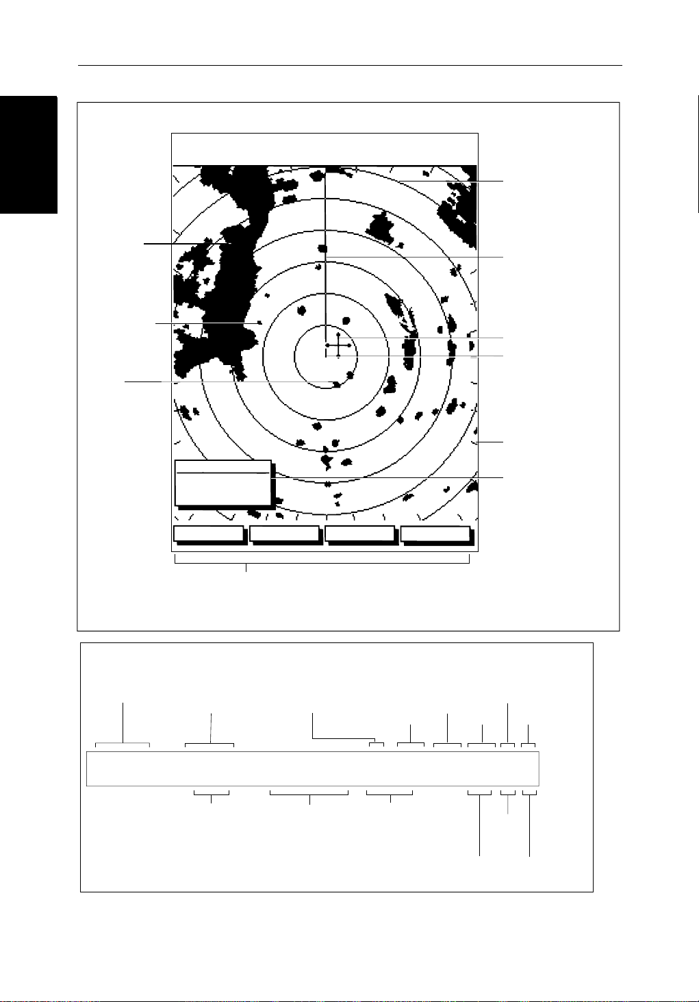
Default Display
Targets:
Landmass
Channel buoy
Surface
vessel
Status Bar
Selected range,
in nautical miles
RM RV3
H-UP
Target Vectors
True Vector or
Relative Vector
and vector length
AUTO
MARPA
T
displayed when function on:
Auto mode
Gain, Sea,
Tune
045°
0.28
RINGS
1/2
R
126°T
Motion Mode
Relative Motion
True Motion
3nm
CURSOR
BRG
RNG nm
HDG MODE TARGETS SCREEN
Default soft key labels
These can be turned off; press any soft key to re-display them.
Different labels are displayed when you press a key.
Range rings
(displayed if
rings are on)
Status Bar
IR
Mode Indicators
Wakes
Range rings
The number and
spacing depend on
the current range, or
you can turn them off
Ship's Heading
Marker (SHM)
You can hide this
temporarily
Cursor position,
controlled by the
trackpad
Ship's position
You can move this
off-centre if required
Bearing scale,
each tick indicating
o
of azimuth
2
Cursor position box
Shows the current
cursor position as
either Range/Bearing
or Lat/Long. You can
move this box to your
preferred position
on the screen, or
turn it off.
Target
Expansion
Guard Zone
Alarms
D3600-6
3nm
RINGS
1/2
Range ring interval
Not displayed if
range rings are off
126°T
Current heading
if data available, or
Course Over Ground.
Displayed in degrees
Magnetic or True
Figure 1-1: Radar Display Features
RM RV3
H-UP
Heading mode
Normally Head Up (H-UP);
Course Up (C-UP) or
North Up (N-UP) can be
selected if heading data
available
AUTO
GST
(Remote rain)
WKS
FTCEXRCGZIR
Rain
Clutter
FTC
Interference
Rejection
D3993-2
Chapter 1: Overview 1-9
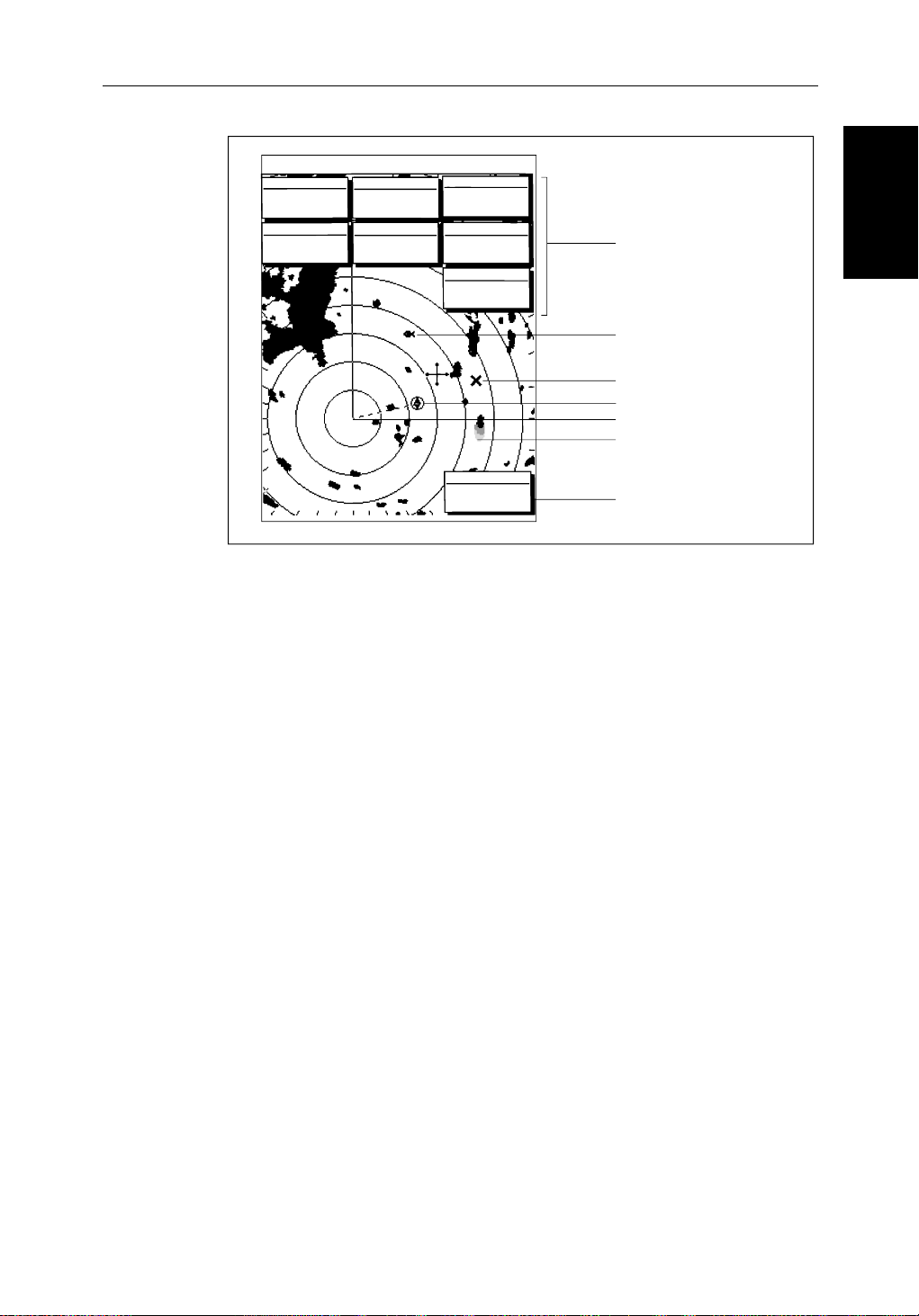
3nm
CURSOR
BRG
063°
1.65
RNG
COG
120@T
Figure 1-2: Typical Radar Picture
Radar Functions
The Pathfinder Radar includes the following functions:
• Choice of range scales from
RR
1/2
POSITION
R
50°49^13N
nm
001°12^09W
6.3kts
126°T
SOG
EX
FTC
AUTO
RC
FTC
TIME
IR
H-UP
GST
13:48:06
SPEED
5.7kts
DEPTH
Data boxes, showing data
(if available) in the selected
units
14.4m
Mark, symbol selected using
setup options
Mark, default symbol
Active waypoint - from Chartplotter
Offset centre
Long target wake (short,
medium or long wakes can
WPT
203°
T 1.20nm
01h:30m
1
/8 nm to 72nm (dependent on scanner type).
be selected)
Waypoint data box, showing
range, bearing and time to go
D3601-2
Radar Functions
Radar Functions
• Automatic and manual control of tuning, gain and sea clutter.
• Two Variable Range Markers (VRMs) and Electronic Bearing Lines
(EBLs), allowing target range and bearing measurements.
VRM/EBLs can be floated.
• Target wakes and target expansion mode.
• Two guard zones with alarms.
• Add marks to record important or dangerous locations.
• Man Overboard (MOB) to navigate back to a person or object.
• 10 Target MARPA
Operation of these radar functions is described in Chapter 3 and Chapter 4.

1-10 SL70MRC & SL70CRC PLUS Pathfinder Radar/Chartplotter Displays
1.3 The Chartplotter Display
The Chartplotter
The Chartplotter
Display
Display
The SL70MRC or SL70CRC display includes a Chartplotter. The chartplotter
includes a small-scale world map and detailed navigation information is
displayed when a cartographic chart card is installed. The details displayed
depend on the chart zoom level selected. A plotter mode is provided to enable
route plotting and tracking at large scales even when a chart card is not
installed, or when the chart is zoomed beyond the available cartographic
detail. A typical chartplotter screen is shown in Figure 1-3.
The chartplotter uses position information from a GPS, DGPS, WAAS or
Loran-C instrument. Once the position fix has been established, your vessel’s
position, if on screen, is shown as a boat shape pointing in the direction of the
current heading (or COG if heading data is not available). If no heading or
COG data is available, the vessel is shown as a circle.
The chartplotter screen includes a status bar that displays chart scale, with
either cursor position, range and bearing or, when the cursor is homed to the
vessel (by pressing
Course Over Ground (COG) and fix type (VES POS, DIF FIX or SD FIX).
The status bar also indicates if radar/chart overlay is switched on.
FIND SHIP), vessel position, Speed Over Ground (SOG),
Any waypoints you have placed are displayed (unless you turned them off in
Chart Set Up as described in Chapter 7) and the current route is shown.
Information can be viewed on-screen by positioning the cursor over a
waypoint, current route or chart object. The chartplotter screen can also show
additional information, depending on your currently selected options, set up
selections and data available from other equipment.
An example chart display, in its default configuration, with a chart card
installed, is shown in the following illustration.
Several functions are available to control the display as follows:
• Zoom in/out and Pan the Display
• Offset the Chart or Center the Chart around the Vessel
• Synchronize the Chart and Radar (if radar data is available)
Operation of these functions is described in Chapter 2.
Chartplotter Display Options
In addition to the display set up options previously described, chart set up
options, described in Chapter 7, allow you to customize the chart by selecting:
• What cartographic features and level of detail are displayed.
• Chart orientation (north up, head up or course up), datums and position offset.
• How waypoints are displayed (symbols and numbers).
• Vectors for heading, COG and tide.
Chapter 1: Overview 1-11
The Screen Presentation Options, described in Chapter 2 allow you to switch
the Chart Grid On/Off and Custom Chart Details On/Off.
Note: When you turn the display off and on again, the Screen Presentation settings are retained in memory.
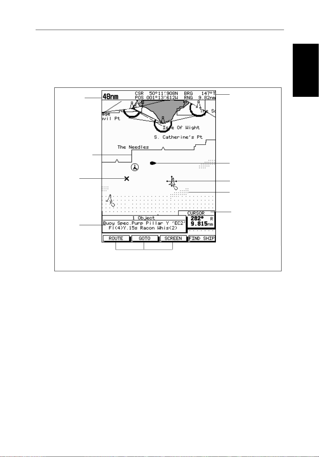
Chart Range
Chart Boundary
Status Bar
Vessel Position
Options
Options
Chartplotter Display
Chartplotter Display
Waypoint
Object data box -
for object selected
by cursor
Figure 1-3: Typical Chartplotter Display
Custom Chart Details
The chartplotter set up options include a sub-menu to customize the
cartographic features. This menu allows you to switch features On, Off, or
control them using the
Custom chart options are as follows:
ON: Chart text, chart boundaries, depth contours, navigation marks
OFF: Caution and routing data.
CUSTOM: Spot sounding, light sectors, marine features.
Default soft key labels
These can be turned off: press any soft key to redisplay them.
Different labels are displayed when you press a key.
CUSTOM soft key. The factory default settings for the
and land features.
Cursor selecting chart object
Depth Area
Cursor position box
Shows the current
cursor position as
either Range/Bearing
or Lat/Long. You can
move this box to your
preferred position on
the screen or turn it off.
D4275-2
Note: The factory default for the
CUSTOM settings is ON.
Icons are displayed in detail, depth shading limit is 10 m and depth contour
display is 0-100 m.
A complete list of chart features is given in Appendix C.

1-12 SL70MRC & SL70CRC PLUS Pathfinder Radar/Chartplotter Displays
Chartplotter Functions
Chartplotter
Chartplotter
Functions
Functions
The Chartplotter includes the following functions:
• Display C-MAP NT C-Card chart information including Ports and Tides
(if available)
• View chart information (if available) for the Nearest Port
• Place, Move, Erase and Edit a Waypoint
• Goto Waypoint or Cursor
• Create, Save, Name, Edit and Follow a Route
• Review Route and Waypoint Lists
• Display vessel’s track; Save and Name the Track for re-call to screen
• SmartRoute to make a track into a route
• Measure Chart Distances and Bearings on-screen
• Set Up Alarms and Timers
• Man OverBoard (MOB) to navigate back to a missing person or object
• Differential GPS set up page
Operation of these functions is described in Chapter 5 and Chapter 6.
Chapter 1: Overview 1-13
1.4 Operating Controls
You operate the radar and chart using a variety of controls:
• A trackpad providing up, down, left, right and diagonal control of an onscreen cursor.
• Eleven dedicated (labeled) control keys.
• Four soft keys with labels displayed on the screen.
• Pop-up menus, displayed on-screen, from which you select options.
• Database lists, displayed on-screen, which enable you to edit items.
Note: The cursor is the cross-hair symbol (+) visible on the display. You move
the cursor using the trackpad and use it to select a position or item on the chart.
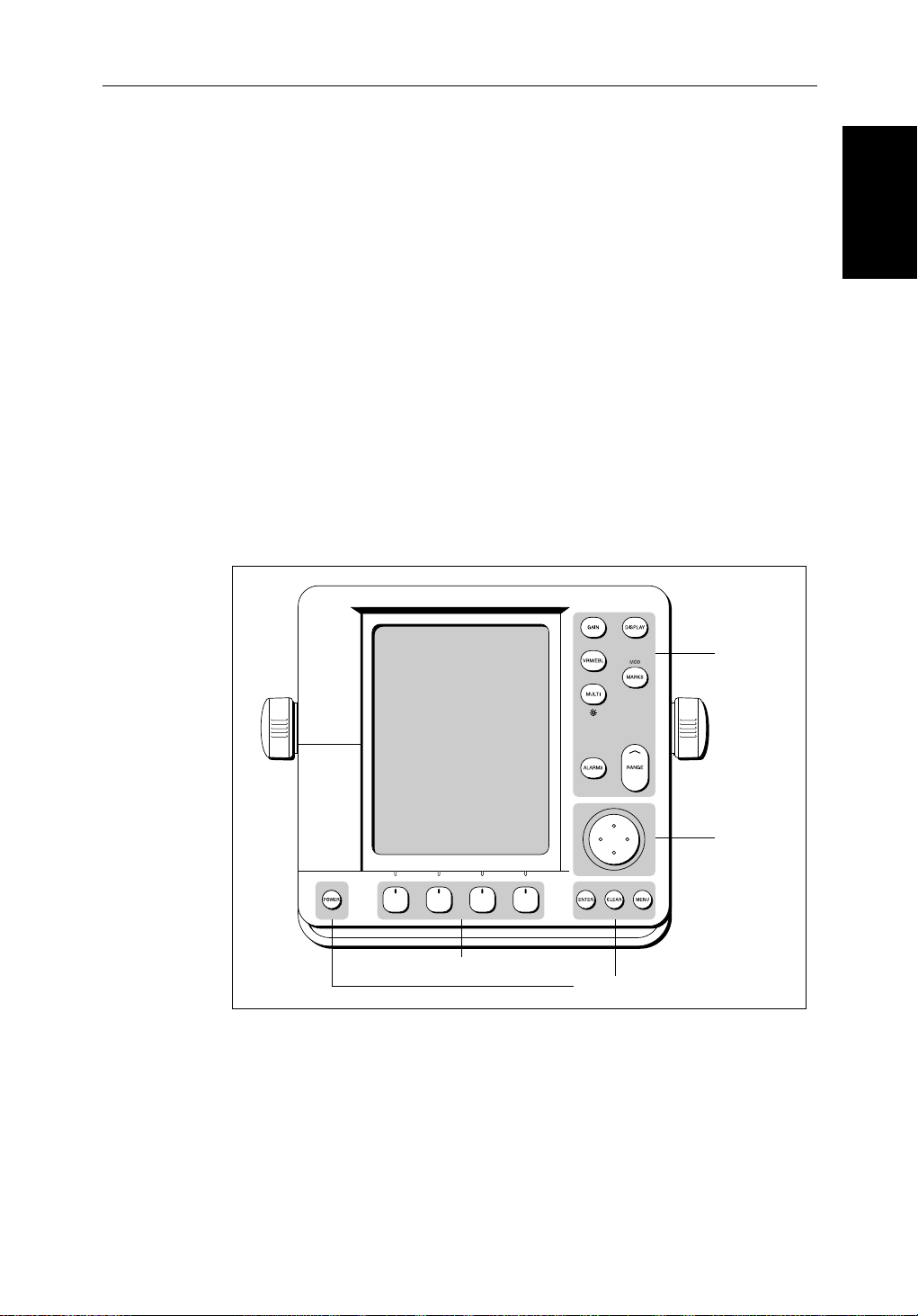
The control keys are shown in Figure 1-4. They are back-lit for night-time use.
When you use a control, a help message is displayed at the top of the screen
(unless you switch help off as described in Chapter 7). The following
paragraphs describe the controls and on-screen facilities.
Operating Controls
Operating Controls
Figure 1-4: LCD Display Control Keys
Trackpad and Cursor
The trackpad has several functions:
• To move the cursor around the screen
Dedicated
keys
Trackpad
Soft keys
Dedicated keys
D3596-3
• To select an item from a pop-up menu
• To adjust a variable soft key control
The cursor is used to:

1-14 SL70MRC & SL70CRC PLUS Pathfinder Radar/Chartplotter Displays
Trackpad and Cursor
Trackpad and Cursor
• Select a position on the screen.
• Select an item, e.g.guard zone on the radar, chart object on the chartplotter.
• Select an area of the radar image to zoom into or pan the chart display..
Moving the Cursor
You can press on any of the four sections of the trackpad to move the cursor in
that direction (up, down, left or right), or press two sections at the same time to
move diagonally. The cursor moves faster as you continue to press the
trackpad. The current cursor position is shown in the cursor data box (if
selected).
Note: During many operations you cannot move the cursor around the
screen; if you cannot move the cursor using the trackpad, check the default soft
keys are displayed (unless they have been switched OFF in system set up). If
not, press
The cursor is normally displayed as a crosshair. However, if you have not
moved the cursor for more than five seconds, when you next move it the cursor
is outlined by a circle so it is easier to locate on the screen.
ENTER until they are displayed.
Context-Sensitive Cursor Control
The cursor is context-sensitive. When the cursor is positioned over special
features on the display a text label appears to identify the feature as detailed in
Table 1-2 .
Moving and deleting items with the context-sensitive cursor
Some items on the radar/chartplotter screen have information associated with
them. Most information is displayed in a data box. The context-sensitive
cursor allows you to move databoxes. It also allows you to move or delete
other items, such as radar guard zones. Further details of items that can be
moved or deleted are given in the appropriate sections throughout this
handbook.
➤ To move any data box or selectable item:
1. Use the trackpad to position the cursor over the item until the item’s label is
displayed.
2. Press
3. Press
ENTER to take control of the item, use the trackpad to move it to the
required position.
ENTER again to fix the position, or press CLEAR to abandon the
move.
➤ To delete an item:
1. Use the trackpad to position the cursor over the item until the item’s label is
displayed then press
CLEAR.

Chapter 1: Overview 1-15
Table 1-2: Context-Sensitive Cursor Text Labels
Text Label Feature Radar/Chart
BOX Data box (any type) Both
MOB Man Over Board marker Both
MRK Radar Mark Both
WPT Chart Waypoint Both
CTR Center of radar Radar
FLT Floating EBL/VRM Radar
GRD Guard zone Radar
MARPA MARPA Target Radar
SHM Ships Heading Marker Radar
VRM/EBL VRM and EBL, 1 or 2 Radar
ZMB Zoom box Radar
Dedicated Keys
Dedicated Keys
➟B
A
COG Course Over Ground vector Chart
HDG Heading vector Chart
POS Vessel’s position Chart
RTE Route leg Chart
TIDE Tide vector Chart
Dedicated Keys
The dedicated keys: DISPL AY, MARKS, GAI N, VRM/EBL, MULTI,
ALARMS, RANGE, ENTER, CLEAR, MENU
functions; the functions are similar on all Pathfinder displays. For example,
ALARMS is used to set up the system alarms on both a chartplotter and a radar.
Some keys can be used in two ways:
• Press: Press the key momentarily and then release it. This method is used
for most key operations.
• Press and hold: Press the key and hold it down for the length of time stated
(for example, 3 seconds), and then release it.
When you press a dedicated key, one of the following happens:
Ruler line Chart
and POWER have fixed
i. The associated operation is actioned, e.g. change chart scale (
ii. A pop-up menu is displayed, providing further options.
iii. A set of soft keys is displayed, providing further functions.
RANGE).
 Loading...