

Page 1

A-Serie
s
y
Multi-function displa
User reference manual
Page 2

Trademarks and registered trademarks
Autohelm, HSB, RayTech Navigator, Sail Pilot, SeaTalk and Sportpilot are UK registered trademarks of Raymarine UK Limited.
Pathfinder and Raymarine are UK registered trademarks of Raymarine Holdings Limited. 45STV, 60STV, AST, Autoadapt, Auto GST,
AutoSeastate, AutoTrim, Bidata, G-Series, HDFI, LifeTag, Marine
Intelligence, Maxiview, On Board, Raychart, Raynav, Raypilot, RayTalk, Raystar, ST40, ST60+, Seaclutter, Smart Route, Tridata and
Waypoint Navigation are trademarks of Raymarine UK Limited.
All other product names are trademarks or registered trademarks of
their respective owners.
© Raymarine UK Ltd. 2008
Document number: 81314-1
Date: August 2008
Page 3

Contents
Important information.............................................9
Warnings and Cautions ....................................................9
Electronic charts.............................................................10
Chapter 2:Using the display................................. 13
Introduction .............................................................14
System overview.....................................................14
Core System...................................................................14
Extended System............................................................15
Applications.............................................................16
First time use...........................................................17
Controls...................................................................19
Operation ................................................................20
Powering the display ON/OFF........................................20
Cursor.............................................................................20
Panning and zooming.....................................................20
Display lighting and color................................................21
Additional screen information..................................22
Setup menus...................................................................24
Dialog boxes...................................................................24
Displaying applications............................................25
Selecting a page set.......................................................25
Selecting an application page.........................................25
Split screen pages...........................................................26
Emergencies and warnings.....................................27
Man overboard................................................................27
Alarms.............................................................................27
Chapter 3:Waypoints ............................................29
Introducing waypoints..............................................30
Using Waypoints .....................................................31
The waypoint toolbar.......................................................31
Creating waypoints..........................................................31
Navigating to waypoints ..................................................32
View / edit waypoint details.............................................33
Moving waypoints............................................................34
Erasing a waypoint..........................................................35
Waypoint groups .....................................................35
Chapter 4:The chart application ..........................37
Chart safety and requirements................................38
Safety..............................................................................38
The chart.................................................................39
Your position ..................................... ... ...........................40
Moving around the chart..................................................40
Autoscale.........................................................................40
Navigating to a specific point...................................41
3
Page 4

Creating a route.......................................................42
Chapter 5:3D chart application............................ 63
Following a route .....................................................44
Editing routes...........................................................45
Timed routes ......................................... ... .......................46
Course deviation indicator .......................................47
Using tracks.............................................................48
Editing and deleting tracks..............................................48
Measuring distance, range and bearing ..................49
Chart presentation...................................................51
Chart layers..................................... ................................51
Vectors and arrows .........................................................51
Chart mode and orientation.............................................52
Chart detail ..............................................................53
Safety and system requirements ............................ 64
Safety.............................................................................. 64
Requirements..................................................................64
3D chart operation .................................................. 64
The controls....................................................................65
Active and Planning modes ............................................65
Changing the view ..........................................................66
Making the view clearer..................................................67
Using the standard and 3D charts together............ 68
3D view locator ...............................................................68
Chart synchronization.....................................................69
Aerial photography overlay..................................... 70
Setting up the 3D chart........................................... 70
Journey planning .....................................................54
Tide and current information ...........................................54
Bathymetric information...................................................56
Details of objects and features........................................56
Details of ports, port and business services....................57
Pilot book information......................................................57
Panoramic and aerial photographs .................................58
Chapter 6:Fishfinder application......................... 71
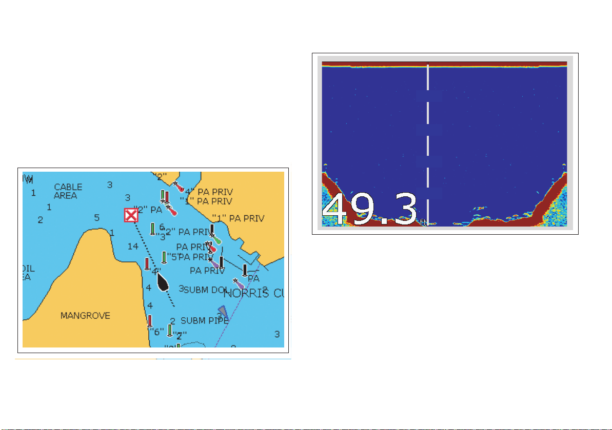
The fishfinder screen .............................................. 72
How the fishfinder works......................................... 72
Interpreting the Fishfinder image............................ 73
Bottom indications...........................................................73
Factors influencing the readout.......................................73
Chart setup..............................................................59
Datum..............................................................................60
Chart offset and cartography setup.................................60
Chart scale ....................................................... ...............62
Alarms.............................................................................62
4 A-Series display - User reference manual
Fishfinder Pre-set operation.................................... 74
Preset display modes......................................................74
Changing the depth range ...................................... 78
Range shift......................................................................78
Page 5

Presentation options ............................................... 79
Gain and power ............................................... .. ............79
Power setting..................................................................80
Dual / Single frequency view ..........................................80
Measuring depth and distance........................................ 81
Adjusting the scroll mode and speed..............................82
Placing waypoints ...................................................83
Fishfinder alarms.....................................................83
Fishfinder Setup Menu............................................84
Screen settings...............................................................84
Transducer settings........................................................86
Chapter 7:Sirius weather (US only).....................87
System requirements..............................................88
Using Sirius Weather .............................................. 88
Creating a weather page ................................................88
The weather display........................................................88
Specifying meteorological elements ...............................89
Moving around the weather map ....................................89
Placing waypoints...........................................................89
Weather symbols...................................................... ... ...89
Precipitation (NOWRad).................................................90
Storm Cast......................................................................90
Sea surface temperature (SST)......................................91
Canadian radar...............................................................91
Tracking storms..............................................................91
Tropical storm data..........................................................92
Lightning..........................................................................92
Surface observation stations...........................................92
City forecasts...................................................................92
Wind................................................................................93
Waves .............................................................................93
Surface pressure.............................................................94
Viewing data for a specific position.................................94
Animated weather graphics.....................................94
Viewing weather reports..........................................95
Watchbox warnings.........................................................95
Displaying marine watchboxes........................................96
Troubleshooting.......................................................96
Weather application setup.......................................96
Chapter 8:Sirius Audio (US only).........................99
Using Sirius Radio.................................................100
Tuning to a channel.......................................................100
Browsing channels........................................................101
Scanning channels........................................................101
Hiding or showing channels and categories. .................101
Presets..........................................................................102
Parental locking.....................................................103
Entering passwords.......................................................103
Favourite song alerts.............................................103
5
Page 6

Chapter 9:Navtex .................................................105
Setting up Navtex ..................................................106
Selecting message alert categories.......................106
The Navtex message window................................106
Managing Navtex messages .................................107
Sorting the message list................................................107
Chapter 10:AIS.....................................................109
Background information.........................................110
Classes of AIS data.................................................. ... ..110
Setting up AIS........................................................111
Using AIS...............................................................111
AIS status icons.............................................................111
AIS Layer.......................................................................112
The AIS screen......................................................... ... ..112
AIS Target symbols.......................................................113
Viewing AIS information ................................................113
Safe zones.............................................................113
Safe zone alarm ............................................................113
AIS display options................................................114
Displaying AIS vectors ..................................................114
Displaying safety-critical AIS data.................................114
AIS list ...........................................................................115
Full AIS data.................................................. ... .............115
AIS Options softkey.......................................................115
Messages and alarms........................................... 116
Safety messages ..........................................................116
AIS alarms ............................................................ 116
Active alarm list.............................................................116
Chapter 11:Data and Engine monitors.............. 119
System requirements............................................ 120
Engine requirements.....................................................120
Data monitoring requirements.......................................120
Data application.................................................... 120
Selecting the data application page..............................120
Preset data panels........................................................121
Engine monitor...................................................... 121
Setting up the engine monitor.......................................121
Preset engine monitor panels .......................................122
Temperature and fuel units...........................................122
Engine monitor alarms..................................................122
Customizing data panels....................................... 123
Chapter 12:System Setup and Customizing .... 125
Page sets............................................................. 126
Databar and Compass.......................................... 126
Compass Setup .................................................... 127
GPS status............................................................ 127
Satellite differential system...........................................128
6 A-Series display - User reference manual
Page 7

COG/SOG filter................................... ..........................128
System-wide settings............................................129
System Setup menu .....................................................129
Alarm Setup Menu........................................................131
Chapter 13:Storing data and Chart / CF cards.135
Card use and information.....................................136
Using the card slot........................................................137
Storing and retrieving data....................................138
Sending and receiving data with a computer........ 139
Password protection..............................................139
Password confirmation .................................................139
Disabled data/functions ................................................140
Enabling and disabling password protection ................140
Chapter 14:Maintenance and troubleshooting. 141
Safety....................................................................142
Routine checks......................................................142
Cleaning........................................................................142
Resetting the system.............................................143
Settings reset ................................................................143
Settings and data reset.................................................143
Contacting Raymarine...........................................146
Using the website..........................................................146
In the US .......................................................................146
In Europe.......................................................................147
Worldwide......................................................................147
Contacting Navionics.............................................147
Navionics Italy...............................................................147
Navionics US.................................................................147
Navionics Australia........................................................147
Navionics UK.................................................................148
Contacting Sirius...................................................148
Navionics license agreement ........................................149
Sirius weather............................................ ... .................150
Troubleshooting ....................................................144
Installation and display .......................................... ... .... 144
Chart application...........................................................145
Weather application......................................................145
7
Page 8

8 A-Series display - User reference manual
Page 9
Important information
Warnings and Cautions
WARNING: Navigation aid
This product is intended to serve only as an aid to
navigation. Use of specific features such as AIS
overlay, and various cartographic aids are meant
only to aid safety and decision-making. These
features cannot be relied upon as complete or
accurate as their use and availability may vary
locally. It is your responsibility to use caution,
sound judgement, official government charts,
notices to mariners and proper navigational ski ll
when using this or any other electronic device.
WARNING: Product installation
This equipment must be installed in accordance
with the Raymarine instructions provided. Failure
to do so could result in poor prod uct performance,
personal injury, and/or damage to your boat.
WARNING: High voltages
The display unit contains high voltages. DO NOT
remove the display unit covers or attempt to
service the equipment.
WARNING: Service and Maintenance
This product contains no user serviceable components. Please refer all maintenance and repair to
authorized Raymarine dealers.
Unauthorized repair may affect your warranty.
CAUTION: CompactFlash cards
When installing CompactFlash cards ensure that
the card is fitted the correct way around. DO NOT
try to force the card into position as this may
result in irreparable damage to the card.
Removing the CompactFlash card while information is being written to or read from it may cause
damage to the card and loss of all data.
DO NOT use a metallic instrument such as a
screwdriver or pliers to remove a card, as doing
this can cause irrep ar able damage.
CAUTION: Water ingress
To prevent the ingress of water and consequent
damage to the display, ensure that the chart card
door is firmly closed. This can be confirmed by an
audible click.
CAUTION: Sun covers
To provide protection against the damaging
effects of ultra violet (UV) light, use the sun covers
when equipment is not in use.
CAUTION: Cleaning
DO NOT use acid, ammonia based or abrasive
products.
DO NOT use commercial high pressure washing
(jet wash) equipment.
Important information 9
Page 10

Electronic charts
Electronic charts are an aid to navigation designed to facilitate the
use of authorized government charts, not to replace them. Only official government charts and notices to mariners contain the current
information needed for safe navigation. The Captain is responsible
for their prudent use. The A-Series Multifunction Display and its
charts do not therefore exclude the user from carrying the required
official charts and documents.
Raymarine does not warrant that this product is error-free or that it is
compatible with products manufactured by any person or entity
other than Raymarine.
This product uses digital chart data, and electronic information from
the Global positioning System (GPS) which may contain errors.
Raymarine does not warrant the accuracy of such information and
you are advised that errors in such information may cause the product to malfunction. Raymarine is not responsible for damages or
injuries caused by you use or inability to use the product, by the
interaction of the product with products manufactured by others, or
by errors in chart data or information utilized by the product and supplied by third parties.
Multi-media chart cards
The A-Series Multifunction Display is compatible with Navionics
chart data. You, you can insert Navionics chart cards into the CompactFlash card slot on the unit.
If your A-Series is pre-loaded with cartography, chart cards can provide alternative cartography regions and features.
When a chart card is present, the A-Series will automatically use the
most recent cartography for the display.
To check the current availability of Navionics chart card types and
the latest feature sets, visit www.navionics.com or www.navionics.it
To obtain Navionics card, contact your local dealer or visit the Navionics website.
Alternatively anywhere in North America call Navionics toll-free on:
1-800-848-5896.
Outside of North America, contact your local dealer or Navionics
SpA on:
Phone: (+39) 0584961696
Fax: (+39) 0584 961309
When archiving data, Raymarine recommends the use of SanDisk
CF memory cards. Other brands of CF memory card may not work
in your unit.
EMC conformance
All Raymarine equipment and accessories are designed to the best
industry standards for use in the leisure marine market.
The design and manufacture of Raymarine equipment and accessories conform to the appropriate Electromagnetic Compatibility
(EMC) standards, but correct installation is required to ensure that
performance is not compromised.
10 A-Series display - User reference manual
Page 11

Declaration of conformity
Raymarine Ltd. declar e th at the A-Series Multifunction Displays are
in compliance with the essential requirements of EMC directive
2004/108/EC.
The original Declaration of Conformity certificate may be viewed on
the relevant product page at www.raymarine.com
Product disposal
The Waste Electrical and Electronic Equipment (WEEE)
Directive requires the recycling of waste electrical and electronic equipment. Whilst the WEEE Directive does not apply
to some Raymarine products, we support its policy and ask
you to be aware of how to dispose of this product.
The crossed out wheeled bin symbol, illustrated above, and found
on our products, signifies that this product should not be disposed of
in general waste or landfill.
Please contact your local dealer, national distributor or Raymarine
Technical Services for information on product disposal.
Warranty
To register your Raymarine A-Series Multifunction Display ownership, please take a few minutes to fill out the warranty registration
card found in the box, or visit www.raymarine.com and register on-
line.
It is important that you register your product to receive full warranty
benefits. Your unit package includes a barcode label indicating the
serial number of the unit. You should stick this label to the warranty
registration card.
About this manual
This handbook contains important information on the operation and
maintenance of all of these models and variants which are intended
for use on leisure marine boats and workboats not covered by International Maritime Organization (IMO) and Safety of Life at Sea
(SOLAS) Carriage Regulations.
Technical accuracy
To the best of our knowledge, the information in this handbook was
correct as it went to press. However, Raymarine cannot accept liability for any inaccuracies or omissions it may contain. In addition,
our policy of continuous product improvement may change specifications without notice. As a result, Raymarine cannot accept liability
for any differences between the product and the handbook.
Important information 11
Page 12

12 A-Series display - User reference manual
Page 13

Chapter 2: Using the display
This chapter gives details of the general operation of the A-Series display.
Chapter contents
• 2.1 Introduction on page 14
• 2.2 System overview on page 14
• 2.3 Applications on page 16
• 2.4 First time use on page 17
• 2.5 Controls on page 19
• 2.6 Operation on page 20
• 2.7 Additional screen information on page 22
• 2.8 Displaying applications on page 25
• 2.9 Emergencies and warnings on page 27
2
13
Page 14
2.1 Introduction
The A-Series Multifunction display combines advanced chart plotting and high definition digital fishfinder technology within a compact
and powerful navigation system.
Your A-Series Multifunction Display comes equipped with a VGA
(640 x 280 pixel) TFT 256 color sunlight viewable display and an
internal high sensitivity GPS module.
A-Series models
• A50 - 5” display, GPS Chartplotter
• A50D - 5” display, GPS Chartplotter/Fishfinder combination
• A57D - 5.7” display, GPS Chartplotter/Fishfinder combination
• A70 - 6.4” display, GPS Chartplotter
• A70D - 6.4” display, GPS Chartplotter/Fishfinder combination
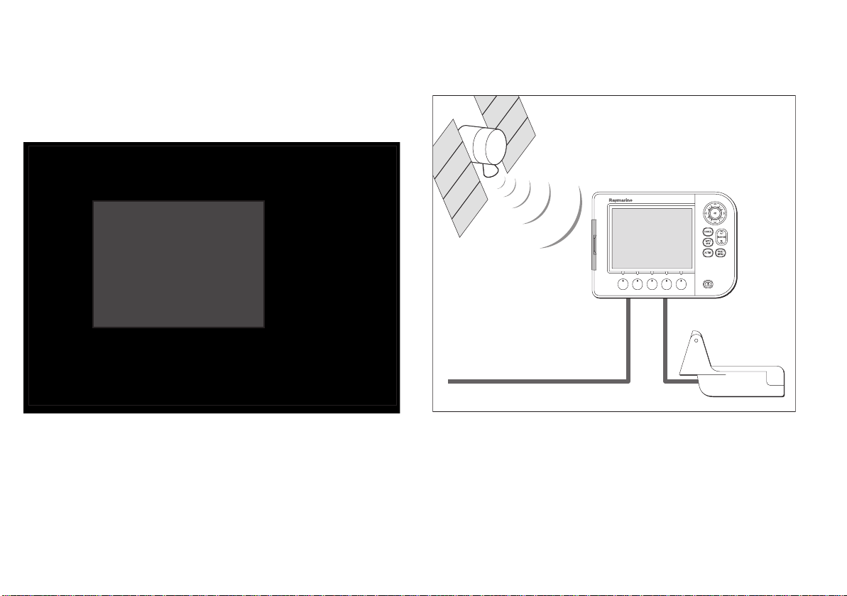
2.2 System overview
Core System
A-Series display
Sonar
transducer
Power IN
D11355-1
14 A-Series display - User reference manual
Page 15
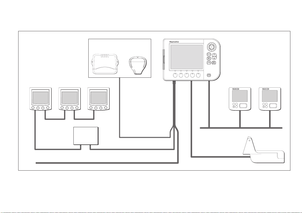
Extended System
Your A-Series may connect to other equipment, for example to share data.
Example extended system
NMEA 0183 devices
Example:
AIS receiver
or
SeaTalk devices
NMEA SeaTalk
converter
SeaTalk NMEA 0183
Power IN
Protocols
The A-Series is compatible with:
• NMEA 0183 (e.g. for AIS, or external GPS connection)
External
GPS
NMEA 0183
A-Series display
•SeaTalk
ng
Pilot
ENTERCANCEL
MENU
SeaTalk
ng
Instrument
ENTERCANCEL
MENU
Sonar
transducer
D11238-2
Chapter 2: Using the display 15
Page 16
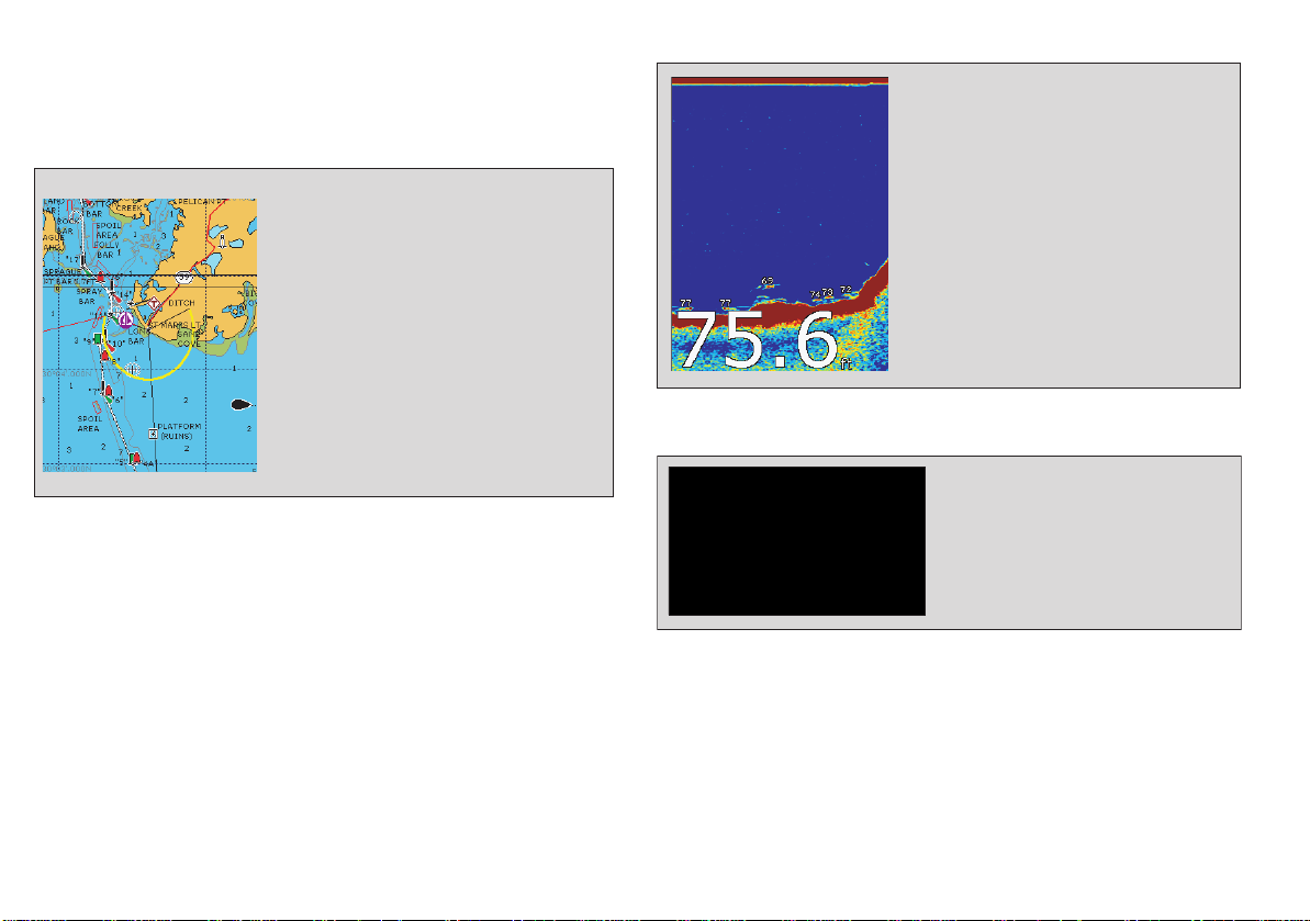
2.3 Applications
Fishfinder (D Models only)
The A-Series features are provided within a number of applications.
Some applications are limited to certain models.
Chartplotter
Locate where you are
•
Interpret your surroundings.
•
Monitor where you are going.
•
Record where you have been.
•
Navigate to a specified position (waypoint).
•
Build and navigate routes.
•
View details of nearby features & services.
•
View details of boats equipped with AIS.
•
Measure distances and bearing
•
s.
See where the fish are.
•
Identify underwater objects.
•
View seabed structure.
•
View sea depth and temperature data.
•
Mark points of interest, like fishing spots
•
or wrecks
Course Deviation Indicator (CDI)
•
'rolling road' in 3D perspective.
•
steer your vessel along a given course.
•
go until you reach a specified point.
View real-time display of your vessel on a
Give details of any correction required to
View data about the distance and time to
16 A-Series display - User reference manual
Page 17

Data
2.4 First time use
View data generated by the system or by
•
instruments available on NMEA 0183,
NMEA 2000 or SeaTalk
3d chart
Requires upgraded cartography (chart card).
Display a 3D view of land, sea & features.
•
Locate where you are.
•
Interpret your surroundings.
•
Monitor where you are going.
•
Go to an existing waypoint.
•
Navigate a route.
•
Synchronize with the 2D chart.
•
Identify fishing spots.
•
When you first use your A-Series Display after it has been installed
ng
.
we recommend that you carry out the following:
Turn on the display
To Power ON:
Press and hold the POWER key until the screen shows
the Raymarine logo.
Select a page set.
When you first turn the display on you will be prompted to select a
page set from those avail ab l e .
Note: You can change the required page set at any time. See
Displaying applications on page 25.
To Select a page set at first time Power on:
1. Use the trackpad Up/Down keys to select the required Page Set.
D9520-1
Highlight appropriate
pre-configured page set
2. Press OK when complete.
Chapter 2: Using the display 17
Page 18

Simulator
Y our A-Series display includes a simulator mode that enables you to
practice operating the unit without data from a GPS antenna or
transducer unit.
Note: The simulator will NOT display any real-data, including any
safety messages (e.g. those received from AIS).
To turn the simulator ON or OFF:
1. Press and hold the PAGE/MENU button to display the setup
menu.
2. Use the trackpad up / down keys to select System Setup.
3. Press trackpad right to select the System Setup options.
4. Select the Simulator option
5. Select ON or OFF as required.
6. Press the OK key to return back through the menus.
18 A-Series display - User reference manual
Page 19
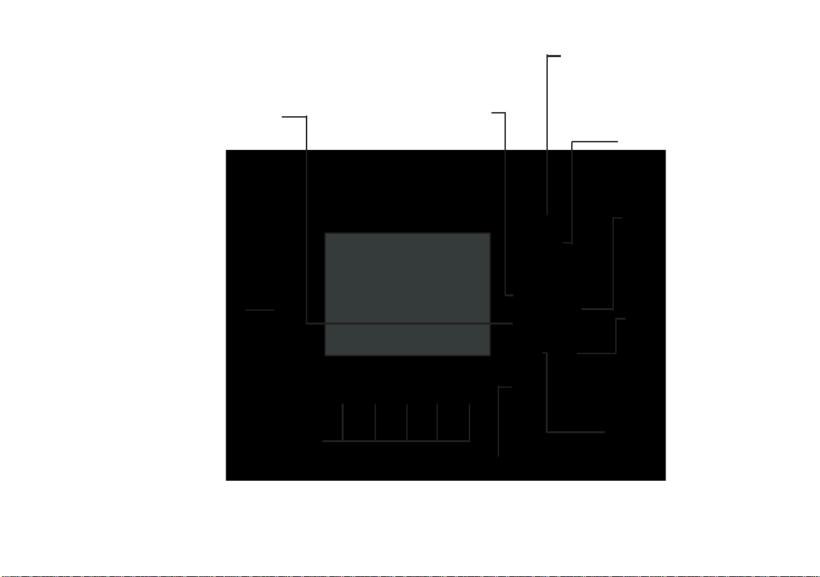
2.5 Controls
WPTS/MOB
Press and release to display the
waypoints softkeys.
Press again to place a waypoint
at your boat's position.
Press and hold to place a Man Overboard (MOB)
marker at your current position
Press to quit the selected
CANCEL
on-screen option when editing data.
Also used to return to the previous
softkey or menu level.
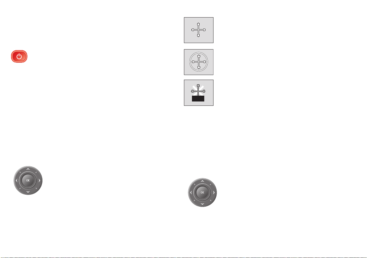
Trackpad
Controls the on-screen cursor.
Also used to scroll through menus.
Press the correspnding edge of the trackpad
to move the cursor horizontally, vertically or
diagonally.
OK
Press to select an on-screen
option or return to the previous
softkey or menu level.
RANGE
Changes the display scale.
Press to display a smaller area
<
on the screen.
<
Press to display a larger area
Chart card slot
Open the cover to install
CompactFlash cards
Press to select the corresponding
function identified by the on-screen
Chapter 2: Using the display 19
Softkeys
label
Press and release to turn ON.
POWER
Press and hold to turn OFF.
PAGE/MENU
Press to display softkeys for
active page.
Press and hold to access the
Setup menu.
ACTIVE
Selects which of the split
windows is active. The
selected screen is outlined
in red and the associated
softkey labels are displayed.
Page 20
2.6 Operation
Powering the display ON/OFF
To Power ON:
Press and hold the POWER key until the screen shows
the Raymarine logo. The unit starts up in the last used
display configuration.
To Power OFF:
Press and hold the POWER key until the power down
countdown reaches zero. The unit is powered OFF.
Releasing the POWER key before the countdown is complete cancels the power off sequence.
Cursor appearance
The cursor appears on the screen as a white cross.
D7366_3
If the cursor has not been moved for a short period of
time, it changes to a circle with a cross in it, to make it
easier to locate on screen.
D7368_2
The cursor is context-sensitive; when it is placed over
an object, e.g. a waypoint or chart feature, it changes
WPT
color and a label or information associated with the
object is shown. Placing the cursor over certain items
D7369-2
will also cause the softkeys to change, enabling you
to access related operations.
Cursor
When you are using chart and fishfinder applications, the cursor is
used to move around the screen.
To move the cursor:
Press the trackpad in the direction you want the
cursor to move.
20 A-Series display - User reference manual
Panning and zooming
In the appropriate chart or fishfinder application windows, you can
pan and zoom the view to show a different geographic area (pan) or
change the scale at which an area is displayed (zoom).
To Pan the view
Use the trackpad to move the cursor to the edge of
the screen, The view automatically moves in the
selected direction to bring a different area into
view.
Page 21

To Zoom in or out
Use the RANGE button to change the scale of the
viewable area. Press ‘IN’ to see a smaller area of the
screen in more detail (large scale). Press ’OUT’ to see
a greater area of the chart (small scale).
The level of cartographic detail available at different scales varies
depending upon the chart card used. Some charts provide more
detail at smaller scales than others.
If you select a chart scale that does not provide cartographic detail
for the chosen area, the chart will use the most detailed level available for the surrounding area and stretch it to fit the selected scale.
This means that you will never have blank or hatched areas on the
screen. However minor misalignment of objects may occur where
they cross the chart boundaries.
Display lighting and color
Your display unit has two distinct color palettes, for day or night
operation. You can also manually adjust the backlight level.
Day/Night operation
Note: The display saves the current palette when the unit is
powered off. A di splay set to NIGHT may be dif ficult to see in
bright sunlight.
Backlight level
To adjust the backlight level:
1. Press the Power key to display the backlight level bar.
2. Use the left / right trackpad keys to adjust the backlight level.
3. Press OK to accept the setting and exit the backlight adjustment.
To select the day/night mode of operation:
1. Press the Power key to display the palette select softkey and
brightness level.
2. Press the appropriate softkey to select between Day and Night
palettes.
Chapter 2: Using the display 21
Page 22
2.7 Additional screen information
Data base lists
Contain information you have added to the
•
display's memory e.g. waypoints.
Highlight an entry using trackpad or rotary
•
control to display related information.
Editable using soft keys.
•
Pop-up messages
Alert you to a situation e.g. alarm, function
•
not available.
Not editable.
•
May require a response e.g. press
•
ACKNOWLEDGE to silence alarms.
Dialog boxes
Enable data to be edited or entered into a
store/list e.g. editing a waypoint.
Status bar
Gives information specific to
•
each application.
Cannot be edited or moved.
•
Data bar
Gives information associated with
•
your boat or the environment.
Customisable content.
•
Vertical or horizontal format.
•
Display or hide.
•
Normal or large size.
•
AIS ALARM
Dangerous Target
Status icons
Confirm status of
Sounder, GPS, AIS and
Autopilot
ACKNOWLEDGE
22 A-Series display - User reference manual
Page 23
Toolbars and softkeys
WAYPOINT AT
CURSOR
A toolbar is a set of softkey labels which appear along the bottom of
WAYPOINT AT
VESSEL
WAYPOINT AT
LAT/LONG...
GO TO WAYPOINT
OPTIONS…
REVIEW AND EDIT
WAYPOINTS
Active waypoint
Steer directionBearing marker
an application page or window.
Pressing a softkey can cause a new toolbar to appear, call up an
options window or menu list, or trigger an action such as setting
your boat on a track to a selected waypoint. Some softkeys have
pop-ups or sliders associated with them, where you make setting
adjustments using the trackpad.
It is useful to think of toolbars as being arranged in tiers. To access
some functions, you need to go to a second or third tier. If you accidentally press the wrong softkey, you can go back up a tier by
pressing the CANCEL button.
If their are additional tiers below a softkey, the softkey label ends
with an ellipsis (...). For example, pressing GOTO.... on the naviga-
tion toolbar opens the GOTO toolbar, enabling access to further
options.
Note: When instructions in this handbook refer to softkey labels,
the ellipsis is not included.
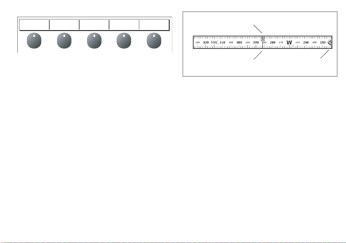
Compass bar
The compass bar gives you a continuous readout centred on your
current heading or course over ground (COG). Arrows at either end
•In heading mode, the bearing marker is RED.
•In COG mode, the bearing marker is GREEN.
• When you use the compass bar with an active waypoint, the
bearing marker is BLUE and the active waypoint symbol indicates the bearing to your waypoint.
You turn the compass bar on and off from the data toolbar.
To turn the compass bar on and off
1. Press and hold the PAGE/MENU button to display the system
setup menu.
2. Use the trackpad up/down to highlight the Databar setup
option.
3. Press the trackpad right to open Databar setup menu
4. Set the Type and Position option to Top Compass.
5. Press OK to save your selection.
Note: When the compass bar is displayed the transducer icons
remain visible in the top-right section of the screen.
of the bar indicate current steer direction.
When displayed, it replaces the databar and is always positioned at
the top of the screen.
Chapter 2: Using the display 23
Page 24
Setup menus
Menus are provided for you to make system or application changes.
To use the Setup menus
1. Press and hold the PAGE/MENU button to open the Setup menu.
2. Use the Trackpad up / down to scroll through the available
items.
The list of items may be longer than the screen; scroll down past
the end of the list to display hidden items.
3. Use the Trackpad right to open a sub-menu or a list of options.
4. Press the OK button to select the required settin g or CANCEL to
go back to the previous screen.
Setup
Chart Setup...
Cartography Setup...
GPS Status...
Compass Setup...
1. Highlight item, using:
2. Select item, using:
Cartography Setup Menu
Chart Display Detailed
Chart Grid On
Chart Text On
Chart Boundaries ON
Spot Soundings ON
Trackpad
(up/down)
Trackpad
(right)
See also
For full details of the setup menus and available settings refer to
System Setup and Customizing on page 125.
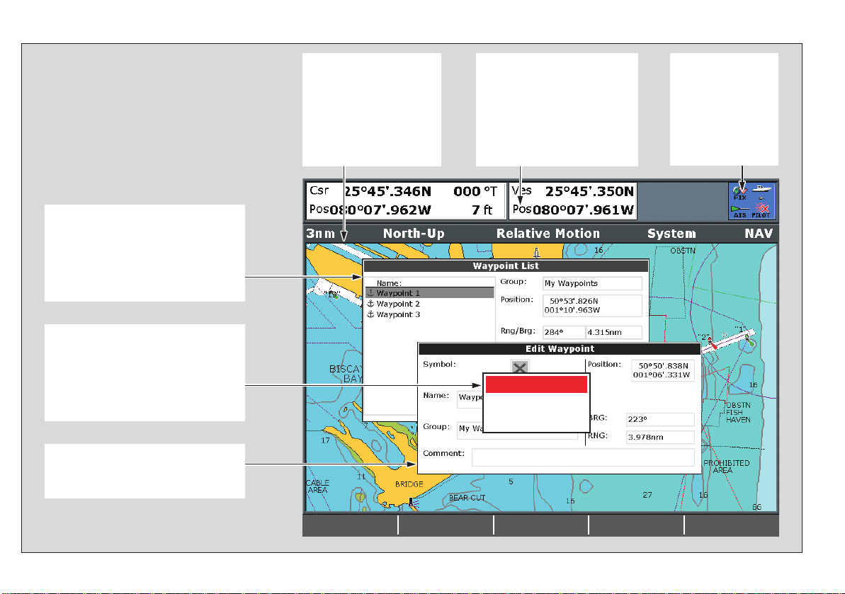
Dialog boxes
Dialog boxes are provided for you to edit or enter data. They appear
automatically at appropriate points. For example if you edit a list of
waypoints, a dialog box appears for you to enter or change a waypoint name.
To enter data into a dialog box
1. Select the appropriate field.
e.g.
Symbol
Name
Group
Comment
Waypoint 1
My Waypoints
Highlight field to be edited
e.g. waypoint
EDIT NAME
Application setup menus are context sensitive: if you are in the chart
application, for example, the chart setup menu is available.
24 A-Series display - User reference manual
Page 25
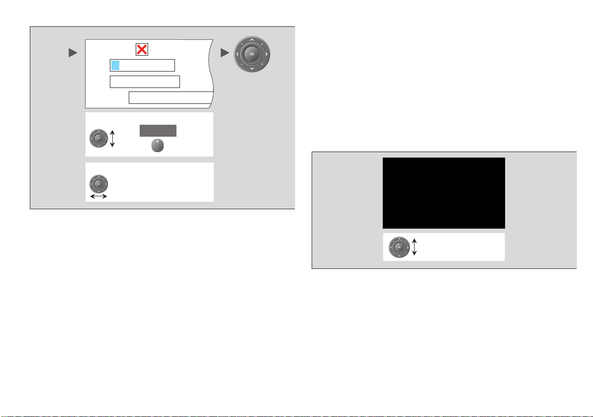
2. Enter the data. Press OK to save the changes.
e.g.
Symbol
Name
Waypoint 1
My Waypoints
Group
Comment
To change character or selection, use:
,
To move to next character for editing, use:
OK
You can enter character text in upper- or lower-case but the system
is not case sensitive: it considers ‘WAYPOINT 1’ to be the same as
‘Waypoint 1’.
To use special or accented characters,
turn on the Extended Char-
acter Set in the System Setup Menu (see System Setup menu on
page 129).
2.8 Displaying applications
The various applications that make up your A-Series system are
arranged in groups called page sets.
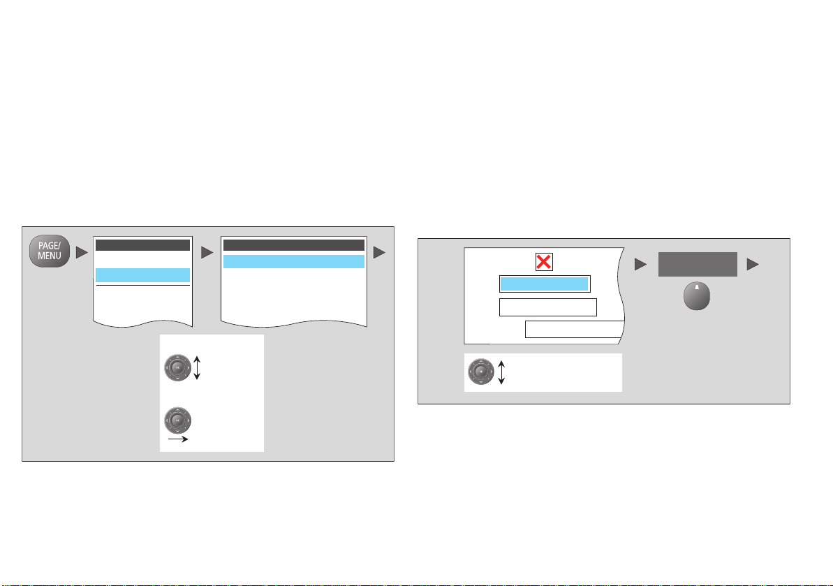
Selecting a page set
To select a page set:
1. Press and hold the PAGE/MENU button to display the setup
menu
2. Choose the Select Page Set option.
Highlight appropriate
pre-configured page set
Selecting an application page
Once you have selected the appropriate page set, as detailed
above, choose the application page that you want to use.
To view an application page:
1. Press PAGE/MENU to show the available pages in the toolbar.
Chapter 2: Using the display 25
Page 26
2. Either select the application page you want from the toolbar or
toggle between the applications configured in the page set by
pressing PAGE/MENU.
3. Press OK or CANCEL.
Split screen pages
When the selected page has more than one application, the window
that is currently active has a red border.
When selecting between active windows, the toolbar changes
accordingly.
Active window highlighted
To change the active window
1. Press ACTIVE to toggle active status between windows (the red
border moves to highlight the active window).
To toggle between split and single window views
1. In a multiple-window view, press and hold the ACTIVE button to
display the active window at full-screen.
2. Press ACTIVE once more to return to multiple-window view.
See also
• You can customize the page sets to contain your own preferred
applications and split-screen layouts. See Page sets on
page 126.
Soft keys associated with active window
26 A-Series display - User reference manual
Page 27
2.9 Emergencies and warnings
You can use your A-Series display to mark the position of a man
overboard (MOB) or to sound an alarm when a particular situation
occurs, e.g. when a depth limit is reached or a specified period of
time has elapsed.
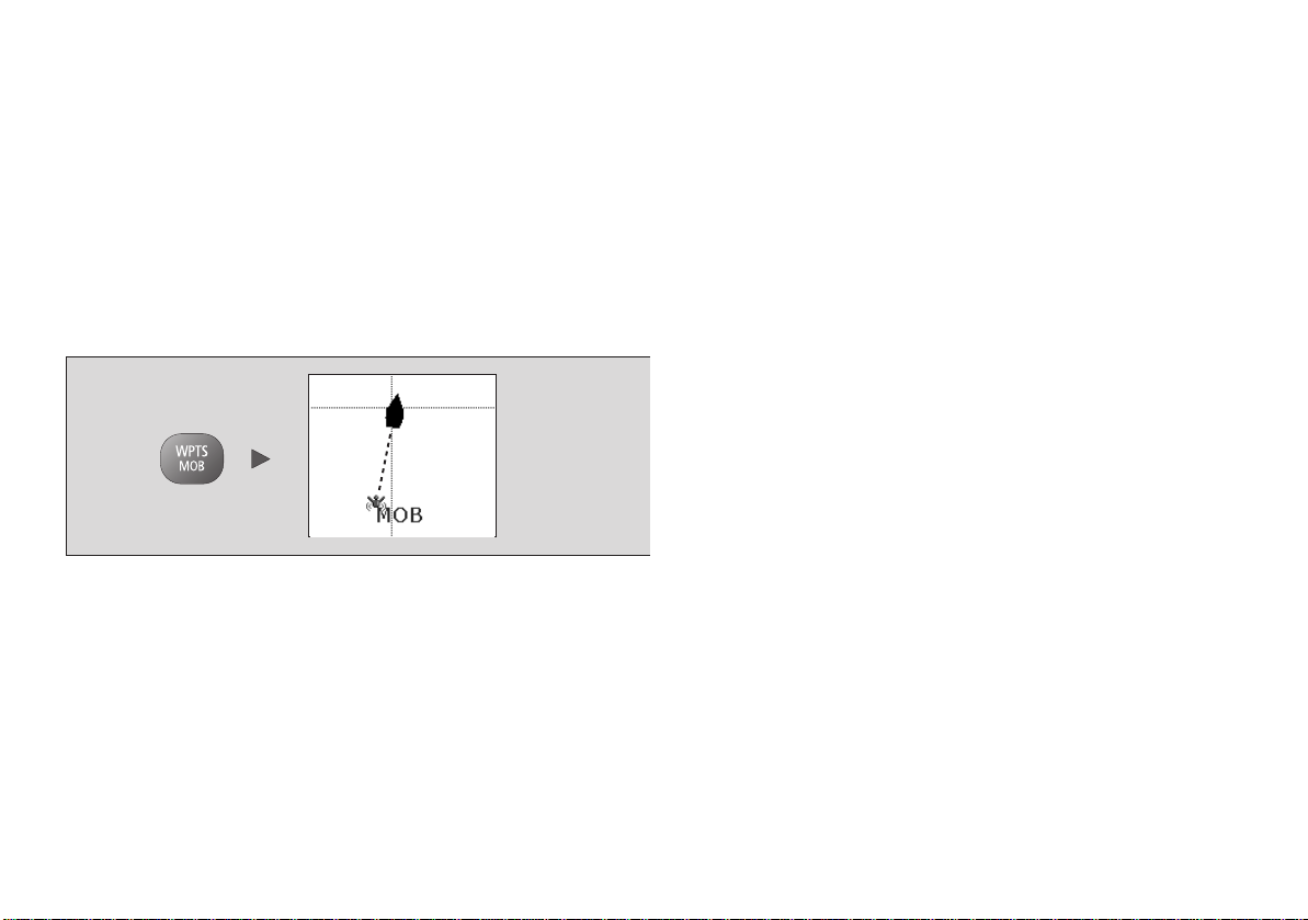
Man overboard
If you lose a person or object overboard and need to return to the
spot, activate the Man Overboard (MOB) function immediately. The
MOB function is available at all times, whatever application is running on the A-Series display.
To activate the Man Overboard function
1. Press and hold the WPTS/MOB
Placing a MOB marker initiates the following actions:
• MOB waypoint placed at your boat’s current position.
• Alarm sounds in morse code (--- letter O) and is repeated every
30 seconds.
• Positional information including bearing, range and position
are displayed in the databar.
key for three seconds.
• Navigation functions are suspended and no new GOTO or
route functions are selectable.
• Motion mode on the chart application is changed to autorange
to show the largest possible scale of chart that will include both
the MOB and your boat.
• Current position to MOB position is represented on-screen by
a dotted line.
Note: To obtain an MOB position, you A-Series display must have
a GPS fix.
To cancel an MOB alarm:
1. Press and hold the WPTS/MOB button for four seconds.
Once the MOB alarm is cleared:
• the chart application motion mode is reset.
• the databar mode is reset.
• GOTO and route functions are restor ed .
Alarms
Alarms are used to alert you of a hazard or particular situation.
When an alarm sounds, a message box appears on-screen to
explain the reason for the alarm.
Cancelling an alarm
There are two types of alarms; system and external.
Chapter 2: Using the display 27
Page 28

• System alarms are triggered by A-Series applications, i.e the
chart or fishfinder. When you cancel a system alarm, the A-Series cancels the alarm and makes appropriate changes to the
application that triggered it. For example, if the chart application
sounds an arrival alarm, navigation to the next waypoint in the
route starts when you cancel the alarm.
• External alarms are triggered by equipment that is connected to
your A-Series system, but which are not part of the system, e.g.
AIS. When you cancel an external alarm, the alarm stops but no
further action is taken.
Both types of alarm are cancelled in the same way.
To cancel an alarm:
1. Press the ACKNOWLEDGE softkey.
See also
Y ou can configure the alarm types and settings for your display . See
Alarm Setup Menu on page 131.
28 A-Series display - User reference manual
Page 29

Chapter 3: Waypoints
This chapter introduces waypoints and explains how to use them for navigation with your A-Series Multifunction
Display.
Chapter contents
• 3.1 Introducing waypoints on page 30
• 3.2 Using Waypoints on page 31
• 3.3 Waypoint groups on page 35
3
29
Page 30
3.1 Introducing waypoints
A waypoint is a position marked on a chart or fishfinder screen as a
reference point or as a place to go to and can be used as a building
block when creating routes. Waypoints are represented on screen
by a symbol and their details stored in a waypoint list.
Waypoints can be created in any application and displayed on the
chart and fishfinder windows.
Chart waypoints
On a 2D chart all waypoints are shown.
The active waypoint (i.e the one to which you are heading) has a
box placed around the symbol to highlight it.
Fishfinder waypoints
On a fishfinder screen the waypoint appears as a vertical line
labelled WPT. This representation cannot be changed.
WPT
WPT
WPT
WPT
30 A-Series display - User reference manual
Page 31

3D chart and CDI waypoints
On a 3D chart or Course Deviation Indicator (CDI) only the active
waypoint is shown.
3.2 Using Waypoints
This section details the creation, navigation and editing of
waypoints.
The waypoint toolbar
You can use the waypoint toolbar to create, edit and navigate to
waypoints.
To display the waypoints toolbar
1. Press the WPTS/MOB button:
Active waypoint
WAYPOINT AT
CURSOR
WAYPOINT AT
VESSEL
WAYPOINT AT
LAT/LONG...
GO TO WAYPOINT
OPTIONS…
REVIEW AND EDIT
WAYPOINTS
Creating waypoints
You can place a waypoint at:
• the cursor.
• your boat’s position.
• a point specified by latitude and longitude or Loran TD coordinates.
To set up your system for Loran TD coordinates refer to System
Setup menu on page 129.
To place a waypoint at the cursor
1. Press the WPTS/MOB button to display the waypoints toolbar.
Chapter 3: Waypoints 31
Page 32

2. Using the trackpad move the cursor to the position where you
want the waypoint.
3. Press the WAYPOINT AT CURSOR softkey.
4. Press OK.
Note: Autopilots must be compatible and connected to the A-
Series display as shown in the installation guide.
For detailed information on navigating with waypoints, see The chart
application on page 37.
To place a waypoint at your boat’s position:
1. Press the WPTS/MOB button.
2. Press the WAYPOINT AT VESSEL softkey.
3. Press OK.
Note: If the system cannot determine your position, a warning is
displayed and the waypoint cannot be placed.
To place a waypoint using coordinates:
1. Press the WPTS/MOB button.
2. Press the WAYPOINT AT LAT/LON softkey.
3. Set the position for the new waypoint.
4. Press OK.
Navigating to waypoints
D8285_1
This section explains how to start and stop navigating to a waypoint.
When you navigate to a waypoint, the data is sent to your autopilot.
The waypoint to which you are navigating is the active waypoint.
To navigate to a waypoint
1. Highlight the waypoint.
2. Press the GOTO WAYPOINT softkey.
or
1. Press either the WPTS/MOB button or GOTO softkey.
2. Press the GOTO WAYPOINT OPTIONS softkey.
3. Select the appropriate waypoint from the list.
4. Press GOTO WAYPOINT.
To stop navigatin g to a wa ypoint
1. Highlight the waypoint.
2. Press the STOP GOTO softkey.
or
1. Press the WPTS/MOB button.
2. Press the GOTO WAYPOINT OPTIONS softkey.
3. Press the STOP GOTO softkey.
32 A-Series display - User reference manual
Page 33

View / edit waypoint details
You can view and edit the details of any waypoint that has been created and stored.
To view waypoint information
1. Highlight a waypoint with the cursor.
2. Press the VIEW AND EDIT DET AILS softkey.
or
1. Press the WPTS/MOB button.
2. Press the REVIEW AND EDIT WAYPOINTS softkey.
Note: Use the second method to view details for an active
waypoint.
Editing waypoint details
When you create a waypoint, the system automatically assigns it a
name, symbol and group. You can change these details and add
comments if required. This is particularly useful if you are managing
large groups of waypoints.
The default waypoint symbol is - X.
You can select different waypoint symbols to differentiate between
groups of waypoints (fishing or diving locations, for example). When
a waypoint is active (being navigated to) it is highlighted by a red
box placed around the symbol.
You can choose any of the following symbols to show your
waypoints:
Default symbol
D9440_1
To edit waypoint details:
1. Press the WPTS/MOB button.
Chapter 3: Waypoints 33
Page 34

2. Press the REVIEW AND EDIT WAYPOINTS softkey
3. Use the trackpad to select the waypoint to be edited.
4. Press the VIEW AND EDIT DETAILS softkey.
5. Make any changes you require.
6. Press OK to save your changes.
7. Press CANCEL to return to normal operation.
Sorting the waypoint list
You can sort the waypoint list to make it easier to manage. This is
particularly useful if you have a large number of waypoints.
To sort the waypoint list:
1. Press the WPTS/MOB button.
2. Press the REVIEW AND EDIT WAYPOINTS softkey
3. Press the SORT LIST softkey.
4. Press the SELECT SORT OPTION softkey.
5. Select a sort method from the list.
6. Press OK. The waypoint list is sorted into the selected option.
Moving waypoints
CAUTION: Moving waypoints
If you move a waypoint that is used in a route, the new
position will be updated within the route. Make sure that this
does not present a navigation hazard.
You can move the position of any waypoint, except an active one.
There are two methods of moving a waypoint, either by dragging it
into a new position using the cursor, or, changing its co-ordinates
within the waypoint list.
To move a waypoint using the cursor:
1. Use the trackpad to place the cursor over the waypoint to be
moved.
2. Press the MOVE WAYPOINT softkey.
3. Use the trackpad to move the cursor and waypoint to the
required position.
4. Press the PLACE WAYPOINT softkey.
To move a waypoint using the waypoint list:
1. Press the WPTS/MOB button.
2. Press the REVIEW AND EDIT WAYPOINTS softkey.
3. Edit the coordinates as required.
4. Press OK to save the new details.
34 A-Series display - User reference manual
Page 35

Erasing a waypoint
You can erase any waypoint, except the active waypoint or one that
is part of a saved route. If you try to erase a waypoint from a hidden
route, a warning message will be displayed.
To erase an on-screen waypoint using the cursor:
1. Use the trackpad to place the cursor over the required waypoint.
2. Press the ERASE WAYPOINT softkey.
3. Press OK to confirm.
To erase a waypoint usin g the way p oin t lis t:
1. Press the WPTS/MOB button.
2. Press the REVIEW AND EDIT WAYPOINTS softkey.
3. Use the trackpad to select the waypoint from the list.
4. Press the ERASE WAYPOINT softkey.
5. Press OK to confirm the deletion. The waypoint is deleted.
To erase all wayp oi nts
1. Press and hold the PAGE/MENU button.
2. Select SYSTEM SETUP.
3. Select ARCHIVE AND TRANSFER softkey.
4. Press the ERASE FROM SYSTEM softkey.
5. Highlight WPT on the SELECT LIST softkey .
6. Select ERASE ALL WAYPOINTS.
7. Confirm the deletion.
3.3 Waypoint groups
All new waypoints are automatically placed in a group called ‘My
Waypoints’. To make waypoints easier to manage, you can organize
them into different groups. When fishing, for example, you can
choose to see only the waypoints in a fishing group that includes all
of your good fishing sites.
Note: A waypoint can only belong to one group.
To open the waypoint group list:
1. Press the WPTS/MOB button.
2. Press the REVIEW AND EDIT WAYPOINTS softkey
3. Press the WAYPOINTS GROUP softkey. The waypoints group
list appears.
You can now:
• Make a new waypoint group.
• Move waypoints between groups.
• Rename groups.
• Erase groups.
To make a new waypoint group
1. Open the waypoint group list.
2. Press the MAKE NEW GROUP softkey.
3. If you want to give the group a name other than the default, press
EDIT GROUP NAME and set the name.
4. Press OK.
To move waypoints between groups
1. Open the waypoint group list.
2. Press the MOVE BETWEEN GROUPS softkey.
Chapter 3: Waypoints 35
Page 36

3. Press SELECT GROUP A and select the group to move the
waypoint from.
4. Press SELECT GROUP B and select the group to move the
waypoint to.
5. Highlight the waypoint you want to move.
6. Press MOVE WAYPOINT FROM A TO B.
7. Press OK when done.
To rename a group
1. Open the waypoint group list.
2. Highlight the group you want to rename.
3. Press the RENAME GROUP softkey.
4. Press the EDIT GROUP NAME softkey.
5. Enter the new name.
6. Press OK.
Deleting waypoint groups
When you delete a waypoint group, the group name and all the
associated waypoints are erased from the system.
If a group contains one or more waypoints that you want to keep,
move these waypoints out of the group as detailed on page 35,
before deleting the waypoint group.
You can erase any waypoint group, except the following:
• the ‘My Waypoints’ group.
• a group containing an active waypoint.
• a group that contains waypoints that are part of a stored route.
3. Press the ERASE GROUP softkey.
4. Press OK to confirm the deletion.
To erase a waypoint group:
1. Open the waypoint group list.
2. Select the group you want to erase.
36 A-Series display - User reference manual
Page 37

Chapter 4: The chart application
The chart application of the A-Series Multifunction Display provides navigation, hazard awareness and planning
features.
Using the chart application you can establish your position, navigate using waypoints and routes, record your
progress and measure distances and bearings:
Chapter contents
• 4.1 Chart safety and requirements on page 38
• 4.2 The chart on page 39
• 4.3 Navigating to a specific point on page 41
• 4.4 Creating a route on page 42
• 4.5 Following a route on page 44
• 4.6 Editing routes on page 45
• 4.7 Course deviation indicator on page 47
• 4.9 Measuring distance, range and bearing on page 49
• 4.10 Chart presentation on page 51
• 4.11 Chart detail on page 53
• 4.12 Journey planning on page 54
• 4.13 Chart setup on page 59
See also…
• The chart application on page 37
• Waypoints on page 29
4
37
Page 38

4.1 Chart safety and requirements
Safety
WARNING: Navigation aid
This product is intended to s er ve o nly as an a id to
navigation. Use of specific features such as AIS
overlay, and various cartographic aids are meant
only to aid safety and decision-making. These
features cannot be relied upon as complete or
accurate as their use and availability may vary
locally. It is your responsibility to use caution,
sound judgement, official government charts,
notices to mariners and proper navigational skill
when using this or any other electronic device.
Always check that your route is safe. Use the RANGE button to
zoom in and check for hazards that may not be visible on a larger
scale view.
Until you are familiar with interpreting the chart display, take every
opportunity to compare what’s shown on the chart display with your
actual surroundings. Practice harbor and coastal navigation during
daylight hours and in clear weather conditions. You can also use the
simulator mode to gain experience in using your display unit.
Before you use the chart application make sure you have read and
understand Chapter 3:Waypoints.
38 A-Series display - User reference manual
Page 39

4.2 The chart
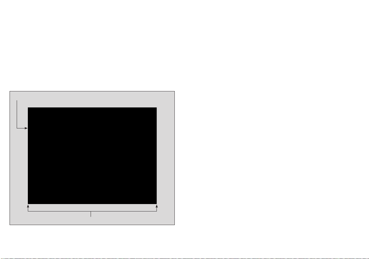
A typical chart view is shown below:
Chart orientation
Chart range
Current
position
Cartographic
object
Chart cards
When a chart card is present, the A-Series will automatically use the most recent cartography for the display.
Motion mode
Chart view
Status
bar
Active
waypoint
AIS
target
Chapter 4: The chart application 39
Page 40

Your position
Your current position is represented by a boat symbol. Your
position is also displayed in the data bar under VES POS.
A solid circle on the chart indicates that neither heading nor
Course Over Ground (COG) data is available.
If your position is outside the area of chart currently shown in the
chart window, the vessel symbol will not be visible. You can tell the
system to locate your vessel and centre the chart display about it.
To locate your vessel
1. Press the FIND softkey to switch between the SHIP and Cursor
location.
Moving around the chart
To move around the chart and display the area required at an appropriate scale, use the track pad and range in/out buttons.
Note: Remember that the cartographic detail available on the chart
will vary according to the chart and chart scale. Some charts
provide details at smaller scales than others.
Autoscale
A feature of the chart application is ‘autoscale’. If you select a chart
scale that does not have cartographic detail in some areas, the
chart will automatically use the most detailed level available for the
surrounding area and stretch it to fit the selected scale. This means
that you will never have blank or hatched areas on the screen. However, there may be some misalignment of objects which cross the
chart boundary in this area.
40 A-Series display - User reference manual
Page 41

4.3 Navigating to a specific point
This is the simplest way of using the chart application for navigation.
A specific point can be either the cursor position or a waypoint contained in the waypoint list.
3. Press the GOTO CURSOR softkey.
A temporary waypoint is placed at the cursor position and data sent
to the autopilot (if attached as part of the system).
When the waypoint is reached it is automatically erased from the
chart.
Example Drg
4nm North-Up (Relative Motion) Local
GOTO CURSOR
STOP GOTO RESTART XTE
Boat's heading changes
to follow course to
temporary waypoint
Press to stop GOTO
and remove
temporary waypoint
Dashed line
marking original
course of GOTO
Temporary waypoint
(within white box)
placed at cursor
To navigate to the cursor position:
1. Use the trackpad to move the cursor to the required position.
2. Press the GOTO softkey.
Temporary
waypoint
name
To navigate to a waypoint:
1. Move the cursor over the required waypoint.
2. Press the GOTO WAYPOINT softkey.
or
1. Press the GOTO softkey.
2. Press the GOTO WAYPOINT OPTIONS softkey to open the
waypoint list.
3. Select the waypoint you want to navigate to.
4. Press the GOTO WAYPOINT softkey.
To stop navigating to a waypoint
1. Press the STOP GOTO softkey.
Maintaining a view of your navigation
With auto range mode the chart automatically adjusts the visible
range to maintain both your boat and the target waypoint on screen,
using the largest scale possible.
D6608-3
To select auto range mode:
1. Press the PRESENTATION softkey
2. Press the CHART MODE AND ORIENTATION softkey
3. Press the MOTION MODE softkey and select AR option.
Chapter 4: The chart application 41
Page 42

4.4 Creating a route
A route is a series of waypoints used to navigate a course. A route is
represented on-screen by a series of waypoints linked together by a
line.
Route name
Waypoint
Up to 150 routes can be added to your unit, each consisting of up to
50 waypoints.
Notes:
• When a route is being built it is not active and does not affect
any current navigation.
• A waypoint can be included more than once in a route, but cannot be used consecutively.
• A new route can be created when the route list is full, but on saving, you will be prompted to choose an existing route to
overwrite.
• You cannot save a new route if any of the waypoints contained
in it are active.
Sunday Trip
Route
destination
Building a route
Routes can either be built on screen or by using the waypoint list
you can:
• Build a temporary route that you follow immediately (Quick
Route).
• Build and save a route for later use, in which case the route is
stored in the route list.
• Convert a track into a route.
To build (and follow) a ro ute us in g ne w wa ypoints
1. Press the ROUTES softkey.
2. Select BUILD NEW ROUTE.
3. Move the cursor to the position that the waypoint is required.
4. Press PLACE WAYPOINT.
5. Repeat steps 3 and 4 until you have built the set of waypoints
needed to make the route.
6. Press SAVE ROUTE or FOLLOW (QUICK) ROUTE.
To build (and follow) a ro ute us in g ex is ting waypoints
1. Press the ROUTES softkey.
2. Select BUILD NEW ROUTE.
3. Highlight the waypoint that you want to use in the new route.
4. Press USE THIS WAYPOINT.
5. Repeat steps 3 and 4 until you have built the set of waypoints
needed to make the route.
6. Press SAVE ROUTE or FOLLOW (QUICK) ROUTE.
To build a new route using the waypoint list:
1. Press the ROUTES softkey.
2. Select BUILD NEW ROUTE.
42 A-Series display - User reference manual
Page 43

3. Press USE WAYPOINT LIST.
4. From the waypoint list, select the first waypoint to be used in the
route.
5. Continue to select waypoints until your route is complete.
Making changes to the route being built
If you make an error whilst building a route you can:
• Undo the last waypoint in an on-screen route build.
• Delete a waypoint from the new route list in a waypoint list route
build.
• Abandon the route build.
To undo the last waypoint in an on-screen build:
1. Press the UNDO WAYPOINT softkey.
The waypoint and its associated dotted line is removed from the
chart and the cursor moves back to the previous waypoint. Pressing
the UNDO WAYPOINT softkey repeatedly will remove successive
waypoints from a route.
To delete a waypoint from the new route list:
1. Use the trackpad to highlight the waypoint to be removed from
the route list.
2. Press the REMOVE WAYPOINT softkey.
The remaining waypoints will renumber accordingly.
Saving a route
Once a route has been built, you have the option to either:
• Save and immediately follow the new route, or,
• Save the new route for later use
A route that is saved and immediately followed is called the ‘Quick
Route’. If a quick route already exists, saving the new route will
overwrite the existing quick route.
To follow the Quick Route:
1. Press the FOLLOW (QUICK ROUTE) softkey.
To Save a route (for later use):
2. Press the SAVE ROUTE softkey. The Save Route Dialog box
appears.
3. Press the EDIT NAME softkey and enter the new route name.
4. Press the EDIT COLOR softkey and enter the new route color.
5. Press OK to accept the changes.
To abandon the route build:
1. Press the CANCEL button.
Chapter 4: The chart application 43
Page 44

4.5 Following a route
You select a route to follow either by ei th er:
• Selecting the Quick Route option at the time you build the route.
See Building a route on page 42
• Highlighting it with the cursor
• Selecting it within the routes list.
When you begin to follow a route it becomes Active.
To select a route to follow with the cursor
1. Move the cursor over either the route line or waypoint symbol.
2. Press the FOLLOW THIS ROUTE or FOLLOW FROM HERE
softkey.
To select a route to follow in the routes list
1. Press either the GOTO or ROUTES softkey.
2. Press the FOLLOW ROUTE OPTIONS softkey.
3. On the Route List menu, select the route you want to follow.
4. Press the FOLLOW ROUTE softkey.
To stop following a route
1. Press the STOP FOLLOW softkey.
To follow a route in reverse order:
1. Press either the GOTO or ROUTES softkey.
2. Press the FOLLOW ROUTE OPTIONS softkey. The route list
appears.
3. Use the trackpad to highlight and select the route you want to
follow.
4. Press the REVERSE AND FOLLOW softkey.
Arriving at a waypoint
As your boat approaches a waypoint arrival alarm provides a warning dialog and an alarm sound.
To acknowledge and proceed to the next waypoint:
1. Press the ACKNOWLEDGE softkey.
See also:
You can set the approach distance (radius) at which the waypoint
arrival alarm will sound. Refer to Alarm Setup Menu on page 131.
Advancing to the next waypoint
You can tell the system to ignore the next waypoint in your route,
and advance directly to the waypoint after it.
Reverse order
This option reverses the waypoints in a route, i.e the last waypoint
of the original route becomes the first, and re-orders the waypoint
accordingly. The route name moves to what is now the first waypoint
and the system automatically activates the reverse follow route
function.
44 A-Series display - User reference manual
To advance to the next waypoint in a route:
1. Either, use the trackpad to move the cursor over the route, or
press the GOTO softkey.
2. Press the ADVANCE WAYPOINT softkey.
Note: If the next waypoint is also the last in the route, pressing
ADVANCE WAYPOINT takes you to the first waypoint in the
route.
Page 45

4.6 Editing routes
A saved route can be edited in a variety of ways, you can:
• Change the course of a route.
• Change the name or color of a route.
• Erase a route.
It is possible to edit an active route with the exception of the target
waypoint.
If a waypoint becomes the target during an edit, the system auto-
matically cancels the edit and the waypoint retains its original
position and data.
To select a route to edit:
1. Press the ROUTES softkey.
2. Press the REVIEW AND EDIT ROUTES softkey. The routes list
appears.
3. Use the trackpad to highlight the route to be edited.
4. Press OK.
OR
5. Use the trackpad to move the cursor over the route to be edited.
6. Press the REVIEW AND EDIT ROUTES softkey.
3. Use the trackpad to highlight the position for the added waypoint
in the right hand column.
4. Use the trackpad to highlight the waypoint you want to add to the
route in the left hand column.
5. Press the INSERT WAYPOINT softkey.
6. Press the SAVE ROUTE softkey.
To create and add a new waypoint to a route:
1. Use the trackpad to move the cursor over the route that you want
to add a waypoint to.
2. Press the INSERT WAYPOINT softkey.
3. Use the trackpad to move the cursor to the position of the new
waypoint.
4. Press the PLACE WAYPOINT softkey.
To move a waypoint within a route:
1. Use the trackpad to move the cursor over the waypoint to be
moved.
2. Press the MOVE WAYPOINT softkey.
3. Use the trackpad and cursor to drag the waypoint to its new
position.
4. Press OK.
Change the course of a route
The course of a route can be changed by adding, moving and
removing waypoints:
To add an existin g wa ypoint to a route:
1. Press the AMEND ROUTE COURSE softkey.
2. Press the USE WAYPOINT LIST softkey. The waypoint list
appears.
Chapter 4: The chart application 45
To remove a waypoint from a route:
1. Use the trackpad to move the cursor over the waypoint to be
removed.
2. Press the REMOVE W AYPOINT softkey.
Change a route’s name or color
If you have many routes stored in your system, it can be useful to
give them individual names or mark them with a color.
Page 46

To change the name and color of a route;
1. Press the ROUTES softkey.
2. Press the REVIEW AND EDIT ROUTES softkey. The routes list
appears.
3. Press the EDIT NAME AND COLOR softkey.
4. Press the EDIT NAME softkey and enter the new route name.
5. Press the EDIT COLOR softkey and enter the new route color.
6. Press OK to accept the changes.
Erasing a route
Any route stored in the route list can be erased, with the exception
of the one that you are following.
Erasing a route will only delete the waypoints used by that specific
route. Waypoints used within other routes are not affected.
To erase a route:
1. Press the ROUTES softkey.
2. Press the REVIEW AND EDIT ROUTES softkey. The routes list
appears.
3. Use the trackpad to highlight the route to be erased.
4. Press the ERASE ROUTE softkey.
Timed routes
Details of all routes are he l d in th e ro utes list. This list can be used
in conjunction with the time and speed over ground (SOG) options
to show a journey time or estimated time of arrival (ETA) and the
actual or planned SOG.
If a route is active, the data will be updated to show bearing, distance and time from your boat’s current position.
To view time and SOG data:
5. Either use the trackpad to move the cursor and highlight a route
on-screen, or, highlight a route in the routes list.
6. Press the ROUTE DETAILS softkey.
7. Togg le between TIME and SOG settings to show the relevant
data as required.
46 A-Series display - User reference manual
Page 47

4.7 Course deviation indicator
The CDI gives you a ‘rolling road’ representation of your progress
toward an active waypoint, with navigation data displayed
alongside.
The rolling road covers an area of sea that corresponds to the Cross
Track Error (XTE) limits specified in the Setup menu.
On course
line
Target
waypoint
Direction of
next waypoint
Steering instructions
The steering instructions below the rolling road tell you what correction is needed to maintain your course and arrive at the target
waypoint.
Instruction Cause
STEER
STARBOARD
XTE error to port is more than a 1/4 of the maximum
XTE error limit in the Setup menu
STEER PORT XTE error to starboard is more than a 1/4 of the
maximum XTE error limit in the Setup menu
Indicator-arrows either side of the steering instruction (pointing
towards the centre line) tell you how great or small the error is. The
greater the error, the greater the number of arrows.
Correct your course by steering in the direction indicated by th e
arrows.
Resetting cross track error
Whilst following a route or navigating to a waypoint, it is possible to
restart the cross track error (XTE). This starts a new course from
your boat’s current position to the current target waypoint.
Target waypoint name
To open the CDI application:
1. Press and hold the PAGE/MENU button.
2. Open the Select Page Set menu.
3. Select a page set that includes the CDI application.
4. Press OK to confirm your selection.
Chapter 4: The chart application 47
Direction
to steer
Direction to steer
to maintain course
The restart XTE function is useful if you find that you are off track
D9515-1
and want to travel directly to the target waypoint, rather than return
D9515_1
to the original track.
Although restarting the XTE causes your boat to change course, it
does not change the saved route.
To restart XTE:
1. With the route active, press the RESTART XTE softkey.
Page 48

4.8 Using tracks
A track is an on-screen trail that represents the course you have
taken. This trail is made up of a series of track points which are created automatically. You can save the track to create a permanent
record of where you have been.
Creating a track
There is a maximum number of track points that can be stored by
your system. A warning will be shown if the track you are creating
uses the maximum number of track points and, if you continue to
record the track, start to overwrite the earliest track points with
newer ones.
To start recording a track;
1. Press the TRACKS softkey.
2. Press the START TRACK softkey.
To stop recording a track:
1. Press the TRACKS softkey.
2. Press the STOP TRACK softkey.
3. Press SAVE TRACK, or DISCARD TRACK depending on what
you want to do with the track.
Creating a route from a track
To create a route from a current track:
This method takes a ‘snapshot’ of the track to date, converts it to a
route and then continues to lay the track.
1. Use the trackpad to highlight the required track.
2. Press the CREATE ROUTE FROM TRACK softkey.
3. Press YES to give the route a name, or NO to store the route with
the next default route number.
To create a route from a saved track:
1. Press the TRACKS softkey.
2. Press the CREATE ROUTE FROM TRACK soft key to open the
track list.
3. Select the track to be converted.
4. Press the CREATE ROUTE FROM TRACK soft key.
Editing and deleting tracks
You can change the name and color of a track, or delete a stored
track using the Review and Edit Tracks functions.
48 A-Series display - User reference manual
Page 49

To select a track for editing:
1. Use the trackpad to highlight the required track.
2. Press the REVIEW AND EDIT TRACKS soft key,
Or
1. Press the TRACKS soft key to open the track list.
2. Press the REVIEW AND EDIT TRACKS soft key.
You can now edit the name and color of a track, or delete it from the
system.
4.9 Measuring distance, range and bearing
The A-Series provides a number of tools to measure distance,
range and bearing.
Distance
Functions
Range Rings Yes (approx.) Yes (approx.) Ruler Yes Yes
Cursor position - Yes Yes
Using the cursor to measure distance and bearing
You can determine the exact position, distance and bearing to the
position of the cursor by referring to the cursor position (Csr Pos)
data in the databar.
between
points
Range from
vessel
Bearing
Chapter 4: The chart application 49
Page 50

Range rings
Range rings are a series of concentric circles a set distance apart.
They are used to help assess the distance between objects on the
chart.
To switch range rings on or off
1. Press the PRESENTATION softkey.
2. Press CHART LAYERS AND DATA softkey.
3. Press CHART LAYERS.
4. Use the TRACKPAD to select the RANGE RINGS layer and turn
them on or off as required.
5. Press OK to save your settings.
Ruler
The chart application includes a ruler which accurately measures
the distance and bearing between two points.
B
A
008oT
0.46nm
To use the ruler
1. Position the cursor at the start-point of the measured distance.
2. Press the PRESENTATION softkey.
3. Press CHART LAYERS AND DATA softkey.
4. Press the RULER softkey.
5. Move the cursor to the end-point of the measured distance.
6. Press OK.
To move the ruler
1. To move the start-point, press ADJUST A.
2. To move the end-point, press ADJUST B.
To clear the ruler
1. Press CLEAR RULER.
50 A-Series display - User reference manual
Page 51

4.10 Chart presentation
The chart has a number of content layers and display modes providing different kinds of display and information.
Vectors and arrows
The vectors and arrows are a chart presentation layer. They present
system data with relation to your vessel on the chart. This can assist
in monitoring your boat’s course.
Chart layers
You can overlay data onto a chart window to give greater depth of
information. The overlays available are:
• AIS Objects
• Range Rings
• 3D locator
• Heading vector
• COG vector
• Tide and wind arrows
To switch layers on or off
1. Press the PRESENTATION softkey.
2. Press CHART LAYERS AND DATA softkey.
3. Press CHART LAYERS.
4. Use the TRACKPAD to select the appropriate layer and turn it on
or off as required.
5. Press OK to save your settings.
Heading vector
(HDG)
Course over ground
(COG)
Wind arrow
Tide arrow
Note: The vectors require appropriate data (e.g. wind data from a
wind instrument, SOG & COG calculated from the GPS fix).
To switch vectors on or off
1. Press the PRESENTATION softkey.
2. Press CHART LAYERS AND DATA sof tkey.
3. Press CHART LAYERS.
4. Use the TRACKPAD to select the appropriate layer and turn it on
or off as required.
5. Press OK to save your settings.
Chapter 4: The chart application 51
Page 52

Vector length
The length of the vectors is determined by the distance your boat
will travel in a given time (This time can be set using the set up
menu) at the current speed.
Wind and tide arrows are shown on the chart as lines with solid
arrow heads pointing in the direction of the wind or tidal set. Wind
arrows point towards your boat, tidal arrows point away from your
boat. The greater the strength of the wind or tide, the thicker the line
appears.
Chart mode and orientation
Mode settings enable you to control how information is shown on
the chart, they let you change such things as how movement is represented, the position of your boat’s on-screen representation and
the chart orientation.
Orientation
Orientation settings control the way the chart is drawn in relation to
your boat’s position and course.
To set the chart orientation:
1. Press the PRESENTATION soft key.
2. Press the CHART MODE AND ORIENTATION soft key.
3. Press the ORIENTATION soft key to toggle it to your preferred
choice.
Orientation options:
• North Up (N-Up)
This is the default mode with the chart static and orientated with
true north to the top of the screen. As your boat’s heading
changes, the boat symbol rotates accordingly.
• Heading Up (H-Up)
In this mode the on-screen boat symbol remains static, with the
current heading facing the top of the screen. When you change
the boat’s heading the chart rotates accordingly. However, to
prevent continual chart rotation as your boat yaws, the chart will
only update if the heading change is 10
select Head-Up mode if the motion mode is set to True.
• Course Up (C-Up)
In this mode the chart is static and orientated with your boat’s
current course facing the top of the screen. As your boat changes heading, the on-screen boat symbol moves accordingly.
When a new course is selected, the chart redraws to show the
new course to the top of the screen.
o
or greater. You cannot
Motion mode
Motion mode controls how your boat’s progress relative to the chart
is represented on screen.
To set the motion mode:
1. Press the PRESENTATION soft key.
2. Press the CHART MODE AND ORIENTATION so ft key.
3. Press the MOTION MODE soft key to select your preferred
option.
52 A-Series display - User reference manual
Page 53

Motion mode options
• Relative motion (RM)
This is the default motion mode. In this mode the chart is redrawn relative to your boat’s position as your journey
progresses, so that your boat is always shown in the same place
on-screen.
• True motion (TM)
In this mode the chart view remains static and your boat is
shown moving across it as progress is made. As the boat’s position approaches the edge of the screen, the chart area is
redrawn to show what is ahead of you.
Note: True motion cannot be selected if the orientation is set to
Head Up.
• Relative motion with vessel offset
In relative motion mode you have the option to specify the position of your boat in relation to the chart view.
4.11 Chart detail
You can change the features and level of detail displayed on the
chart. For example you may wish to hide certain features if there are
many objects displayed in a small geographic area.
Show / Hide waypoints, routes and tracks
There are a number of options to show / hide various aspects of the
waypoint, route and track information .
To show or hide waypoints by group or symbol
1. Press the PRESENTATION softkey.
2. Press SHOW/HIDE WAYPOINT S.
3. Togg le between SYM and GROUP on the SHOW BY softkey.
4. Select the relevant group and toggle its setting to SHOW or HIDE
on the ON CHART softkey.
To show or hide waypoint names
1. Press the PRESENTATION softkey.
2. Press SHOW/HIDE WAYPOINT S.
3. Toggle to the required setting with the WAYPOINT NAME
softkey.
To show or hide waypoint index numbers
1. Press the ROUTES softkey.
2. Press SHOW/HIDE ROUTES.
3. Togg le settings with the WAYPOINT INDEX softkey.
To show or hide routes and tracks
1. Highlight a route or track and press the HIDE softkey.
Chapter 4: The chart application 53
Page 54

or
1. Open the Route or Track list.
2. Highlight a route or track in the list.
3. Tog gle between SHOW and HIDE settings with the ROUTE ON
CHART or TRACK ON CHART softkey.
Note: The active route is always displayed irrespective of the
display status.
4.12 Journey planning
Your electronic charts contain a number of features to help you plan
your journey.
Note: Certain features require additional or upgraded cartography
available within Navionics chart cards. For full details of all
the features available with each card type, refer to the Navionics website - www.navionics.com or www .navionics.it
Declutter
Declutter allows you to reduce the amount of detailed information
shown on the chart.
To turn declutter ON or OFF:
1. Press the PRESENTATION soft key.
2. Press the DECLUTTER soft key to toggle ON or OFF as
required.
Turning the declutter feature ON hides the following cartographic
objects:
• Chart boundaries
• Spot soundings
• Depth contours
• Light sectors
• Cautions and routing data
• Land and marine features
• Business services (if available on the cartography you are using)
If using declutter does not hide a particular feature, you can hide
features individually using the Cartography Set Up Menu.
54 A-Series display - User reference manual
Tide and current information
CAUTION: Tides and currents
Whilst every effort is made to ensure the accuracy of data
used for tides and currents, this information can be
influenced by local conditions. It is therefore
recommended that consideration is given to obtaining
local information wherever possible.
Tidal diamonds
Tide and current information is associated with the tidal diamonds
on the chart.
To show information using a tidal diamond:
1. Use the trackpad to move the cursor over the required tidal or
current diamond.
2. Press OK. A dialog box appears showing tidal or current
information as appropriate for the selected area.
Page 55

3. Press the TIDAL DATA or CURRENT DATA soft key. A dialog
box appears containing additional data and a tidal or current
curve as appropriate for the selected area.
You can now use the trackpad to select the relevant time and the
soft keys to select the relevant date.
3. Press the ANIMATE soft key. The animation screen opens with
the animation paused.
4. Press the ANIMATION PLAY/PAUSE soft key. The animation
starts. The time and date of the animation is shown in the status
bar; the animation always starts from the current time.
To show information using the FIND NEAREST soft key:
1. Use the trackpad to move the cursor to the required position.
2. Press OK.
3. Press the FIND NEAREST soft key. A dialog box appears listing
the available options.
4. Use the trackpad to highlight Tidal Stations or Current S tations as
applicable.
5. Press the FIND soft key. A dialog box listing the nearest stations
appears.
6. Use the trackpad to select and highlight the required station.
Controlling the animation
When you open the tide and current animation screen, the toolbar
shows a set of soft keys that enable you to control the animation:
• Start/Stop the animation.
• Step the animation forward or back in time.
• Set the size of the step.
• Select a date for the animation.
The animation plays in a loop; when it reaches the end of a 24-hour
period, it starts again at the beginning.
7. Press OK.
8. The relevant information is shown in the dialog box.
To start or stop an animation:
1. Press the ANIMATION PLAY/PAUSE soft key.
Animated tide and current data
Requires navionics chart card with animated tide data.
To step through an animation:
1. Press the STEP BACK or STEP FWD soft keys as required.
The animations provide a visual cue to the movement of currents
and tides for times which you have specified.
Animations cover a 24-hour period and you are able to choose
whether to view the whole or part of it. You can also choose to view
the animation continuously or step through it in increments.
To view animated tide and current data:
1. Use the trackpad to move the cursor over the required tidal or
To set the step interval:
With the animation paused:
1. Press the SET TIME INTERVAL soft key.
2. Use the trackpad to adjust the time interval within the range of 15
to 120 minutes.
3. Press OK to save the new time interval.
current diamond.
2. Press OK.
Chapter 4: The chart application 55
Page 56

To set the animation date:
4. Press the SET DATE soft keys. The following soft key options
appear in the toolbar:
TODAY’S DATE Set the animation date to the current date
PREV DATE Set the animation date to 24-hours previous to the
current date
NEXT DATE Set the animation date to 24-hours after the current
date.
EDIT DATE Opens the edit date dialog box: use the trackpad to
enter the date of the animation required
5. Press OK to save the new date and return to the tide/current
animation screen which will update to show the animation for the
selected date.
Press CANCEL at any time to return to the tide/current an i m a ti on
screen with the date unchanged.
Bathymetric information
Requires navionics chart card with bathymetric (Fish’n’Chip) data.
To show bathymetric information:
1. Press the PRESENTATION softkey.
2. Press the CHART LAYERS softkey.
3. Press the CHART TYPE softkey.
4. Toggle the soft key between FISH and NAV according to your
requirements.
• FISH - shows bathymetric information/
• NAV - shows the standard chart view.
If FISH is selected and no data is available for the current position,
(FISH) is shown in the databar to indicate that the system is in
bathymetric mode but does not have data.
Details of objects and features
Many objects shown on the chart have detailed information associated with them. Some of this information is shown automatically
whenever the object is highlighted with the cursor.
To view details of objects or features:
1. Use the trackpad to move the cursor over an object.
If basic information is available for the object it will be shown.
2. Press OK.
3. If available, detailed information for the object is shown.
To find nearby objects or features:
1. Use the trackpad to move the cursor over an object.
2. Press OK.
3. Press the FIND NEAREST softkey.
4. Select the appropriate options from the on-screen lists.
56 A-Series display - User reference manual
Page 57

Details of ports, port and business services
Requires navionics chart card with port and business services data.
Various symbols on the chart indicate the location of business ser-
vices and points of interest.
These locations are indicated using the following symbols.
Business services/points of interest symbols
Anchorage
Fishing
equipment
repairs
Taxi
station
Using the trackpad to place the cursor over a symbol and pressing
OK causes a pop-up to appear, giving the following information:
• Port/Port or Business service name.
• Address.
• Telephone number.
Airport Babysitting Barber Bank Camping Car hire
Gas/Petrol
MarinaNautical
information
Parking
TrainTourist
Golf
Wate r
transport
Post OfficePoliceMuseum
Weather
station
Restaurant
repairs
Firemen
LaundryHotelHospitalGym
ShopShip
• Type of business/services available.
To display port services
1. Highlight a port symbol.
2. Press OK.
3. Highlight a service.
4. Press the VIEW DETAILS softkey.
or
1. Press OK.
2. Press the SEARCH BY NAME softkey.
3. Press EDIT NAME.
4. Enter the port name (or the first few characters of the port name).
5. Press SEARCH.
6. If the search returns more than one port, select the port you are
interested in.
7. Select your service.
8. Press the VIEW DETAILS softkey.
Pilot book information
The pilot book information option enables you to view detailed information normally contained in a nautical pilot book.
To view pilot book information
1. Highlight a port symbol.
2. Press OK.
3. Select Pilot Book and press VIEW PILOT BOOK.
4. Use the toolbar to navigate around the pilot book.
Chapter 4: The chart application 57
Page 58

Panoramic and aerial photographs
Requires navionics chart card with aerial photography.
In some regions an aerial photo overlay is available to enhance your
chart view. The overlay covers navigable waters and an area up to 3
miles from the coast including US lakes and inland waters.
The availability of a panoramic photograph is indicated on the chart
by the camera icon. This is placed on the chart at the point the photograph was taken, with the viewpoint indicated by the angle of the
icon.
To show a panoramic photograph:
1. Use the trackpad to move the cursor over the camera icon.
2. Press OK. The panoramic photograph appears.
or,
1. Use the trackpad to move the cursor over a port symbol.
2. Press OK. The port information dialog box appears.
3. Use the trackpad to highlight PHOTOS.
4. Select a numbered photograph from the list.
5. Press the VIEW PHOTO soft key.
To overlay aerial photography:
1. Press the PRESENTATION soft key.
2. Press the CHART LAYERS soft key.
3. Toggle AERIAL OVERLAY to ON or OFF as required.
4. Use the trackpad Left / Right to set the overlay opacity.
Overlay area
You can choose whether the aerial overlay is shown for land areas
only, or for land and sea areas.
• On land shows a normal chart view for sea areas and overlays
aerial photography on areas of land. This can help interpret your
surroundings while keeping important navigational data visible.
• On land and sea shows aerial photography of both land and
sea areas. This can help in distinguishing between deep and
shallow water (dark blue and light blue, respectively), and to
view land features simultaneously.
The overlay area can be set up using the Aerial Photo Overlay functions of the Cartographic Setup Menu.
To specify the overlay area
1. Open the Cartography Setup Menu.
2. Select Aerial Photo Overlay.
3. Choose your preferred setting.
58 A-Series display - User reference manual
Page 59

4.13 Chart setup
There are three ways you can change chart settings:
• Chart Setup Menu.
• Cartography Setup Menu.
• Presentation softkey (see page 51).
Changes are retained when you power off.
To open the Chart Setup Menu
1. Press and hold the PAGE/MENU button.
2. Highlight Chart Setup.
3. Press the right-arrow on the trackpad.
FUNCTION OPTIONS
Vector Width
Sets the width of the COG and
HEADING chart vector lines.
Record Vessel Track By Auto
Thin
Normal
Wide
System automatically creates track points.
Time
For track point creation by a specified time.
Distance
For track point creation by a specified
distance.
FUNCTION OPTIONS
Object Information OFF
No info pop-up is displayed but detailed
data can still be displayed by pressing OK.
All ON
Displays an information pop-up for all
objects.
Points ON
Displays an information pop-up for objects
selected with the cursor only.
Vector Length
Specify a time period for drawing
COG and heading vectors.
Chapter 4: The chart application 59
3 Mins
6 Mins
Infinite
Track Interval
Option availability depends upon
Record Vessel Track By setting.
Datum
See additional information
below.
Chart Offset
Corrects positional errors in
cartography.
Time
Specify time between track points.
2/5/10/30 seconds
1/3/5/10/30 minutes
Distance
Specify distance between track points.
0.02/0.05/0.1/0.2/0.5/1.0 nm
WGS 84.
List of datum provided.
ON
OFF
Page 60

Datum
The Chart application and your paper charts must use the same
datum to correlate accurately. The default datum for the display is
WGS1984. If that is not suitable, you can change it to one from the
set provided under the Datum option on the Chart Setup menu.
If you have a Raymarine GPS attached, it will automatically update
when you adjust the datum. If you use a third-party GPS, you need
to update its datum separately.
CAUTION: Changing the chart datum does not cause any
waypoints or routes stored in the chartplotter to move on
the display, although their latitude and longitude changes to
reflect the new datum. When you add waypoints to the
waypoint list, make sure they are referenced to the same
datum.
4. Adjust the North/South and East/West offset values by pressing
the corresponding softkey and using the trackpad.
To restore chart offset to zero
1. Select Chart Offset in the Chart Setup Menu.
2. Press the SET OFFSET softkey.
3. Press CLEAR OFFSET.
To open the Cartography Setup Menu
1. Press and hold the PAGE/MENU button.
2. Highlight Cartography Setup.
3. Press the right-arrow on the trackpad.
FUNCTION OPTIONS
Chart Display
Chart offset and cartography setup
This feature allows you to move the position of the chart to correct
positional errors in the cartography. The adjustment is indicated as a
distance north/west (+ve) or south/east (-ve) from your vessel to a
maximum of 1000m. An indicator in the chart window tells you when
chart offset is enabled.
Restore chart offset to zero when you begin using a chart with the
correct georeference.
Please report chart errors to Navionics (see page 147).
To change chart offset
1. Select Chart Offset in the Chart Setup Menu.
2. Toggle OFFSET to ON.
3. Press the SET OFFSET softkey.
60 A-Series display - User reference manual
The level of detail shown on the chart.
Chart Grid
Grid lines of latitude and longitude.
Chart Text
T ext appearing on the chart e.g. place names
etc.
Chart Boundaries
The line indicating the extent of the chart.
Spot Soundings
Number on the chart indicating depth.
Simple
Detailed
Extra detailed
ON
OFF
ON
OFF
ON
OFF
ON
OFF
Page 61

FUNCTION OPTIONS
FUNCTION OPTIONS
Safety Contour
Areas with depths shallower that the specified value are shaded in a darker blue than
those areas with depths greater than the
specified value.
OFF
7ft
10ft
16ft
20ft
33ft
66ft
(Contour always drawn at or
deeper than the selected
depth).
Depth Contour
Set the interval for depth contours.
OFF
16ft
20ft
33ft
66ft
ALL
Hide Rocks ON / OFF
Nav. Marks ON
OFF
Nav. Marks Symbols
The set of symbology used for navigation
International
US
marks. Corresponds to paper charts.
Light Sectors
The sector of light cast by a fixed beacon.ONOFF
Marine Features
Cables, nature of seabed points, tide station,
current stations and port information.
Land Features
The cartographic features that are displayed
on the land.
Colored Seabed Areas
In available areas (e.g. Portugal) this gives
greater definition of seabed.
Background Color
The color of background water when there is
no Navionics cartography.
Business Services
The symbols indicating the location of a
business
Aerial Photo Overlay
The area displaying the aerial photo overlay
Roads
Major coastal roads
Additional Wrecks
Extended wrecks data for new wrecks
ON
OFF
ON
OFF
ON
OFF
White
Blue
ON
OFF
On Land and Sea
On Land
ON
OFF
ON
OFF
Caution & Routing Data ON
OFF
Chapter 4: The chart application 61
Page 62

Chart scale
Use the Range key to change the scale of your chart view. When
you zoom in, you see a smaller area of the chart in more detail
(larger scale). When you zoom out, you see a greater area of the
chart in less detail (smaller scale).
The level of cartographic detail available at different scales varies:
some charts provide detail at smaller scales than others.
If you select a chart scale that does not provide cartographic detail
for your chosen area, the chart will use the most detailed level available for the surrounding area and stretch it to fit the selected scale.
This means that you will never have blank or hatched areas on your
screen. However, there could be some misalignment of objects
which cross the chart boundary in this area.
Alarms
With the appropriate equipment installed and po wered up, the following alarms may be triggered in the chart application:
• System (anchor, timer, alarm clock and temperature)
• Navigation (arrival and off-track)
• Fishfinder
•AIS
• Weather
When an alarm is triggered, a buzzer sounds and a pop-up window
describing the alarm and how to clear it is displayed. In some cases,
appropriate action is taken automatically by the A-Series unit. For
example, following an arrival alarm, the next route leg is activated.
2. Select Alarm Setup.
3. Choose the appropriate sub-menu.
4. For detailed information about alarm configurations, see Alarm
Setup Menu on page 131.
To configure alarms
1. Press and hold the PAGE/MENU button to open the Setup menu.
62 A-Series display - User reference manual
Page 63

Chapter 5: 3D chart application
REQUIRES UPGRADED CARTOGRAPHY
The 3D chart gives you an accurate, three-dimensional view of the area around your vessel. This can help you navi-
gate more confidently if the area is new to you or if visibility is poor.
Navigation functions are availab l e i n th e 3D cha r t .
Chapter contents
• 5.1 Safety and system requirements on page 64
• 5.2 3D chart operation on page 64
• 5.3 Using the standard and 3D charts together on page 68
• 5.4 Aerial photography overlay on page 70
• 5.5 Setting up the 3D chart on page 70
See also…
• The chart application on page 37
• Waypoints on page 29
5
63
Page 64

5.1 Safety and system requirements
5.2 3D chart operation
Safety
WARNING: Navigation aid
This product is intended to s er ve o nly as an a id to
navigation. Use of specific features such as AIS
overlay, and various cartographic aids are meant
only to aid safety and decision-making. These
features cannot be relied upon as complete or
accurate as their use and availability may vary
locally. It is your responsibility to use caution,
sound judgement, official government charts,
notices to mariners and proper navigational skill
when using this or any other electronic device.
Requirements
For the 3D chart application to operate correctly, your A-Series Multifunction Display System requires:
• A Navionics Chart card containing 3D cartography. (Not included with A-Series product)
Range
Horizontal distance across
screen (halfway up the window
or at center of view). Shown in
selected system units.
Cartographic objects
Select objects for display
via the 3D Chart Setup
menu.
Waypoint
With arrival
circle
Mode
Shows mode
application is
working iin.
Boat symbol
Boat's position on
chart. Select sail
or power boat.
Center-of-view
White cross indicates
center of chart view
at sea level.
Rotation
Shows in degrees true,
how far the on-screen
view has been rotated
from your boat's heading.
Depth scale
Approximate
depth beneath
your boat.
North arrow
3D indication of True
North in relation to
the chart view.
The 3D chart view includes the same cartographic objects and navigation features, like waypoints, as the standard chart. To move
around the 3D chart, and to display your chosen area at the required
scale, use pan and zoom as normal.
D8250_1
64 A-Series display - User reference manual
Page 65

The 3D chart has the following features:
• Choice of operating modes; Active or Planning.
• Ability to change the view point.
o
•360
•1
• Ability to exaggerate the view.
• Ability to synchronize 2D and 3D charts.
• Ability to indicate the area that your fishfinder transducer cone
rotation of the selected view.
o
- 90o pitch angle.
covers - if fitted.
Active and Planning modes
You can choose to view the 3D chart application in one of two
modes:
• Active action mode.
• Planning mode.
Active mode is the default mode when entering the 3D chart
application.
To select Planning mode:
1. Use the track pad to move around the map. The chart will enter
planning mode.
The controls
The 3D chart is operated in aa similar way to a conventional chart
using the following controls:
Pan and Zoom
• Range button to zoom in or out.
• Trackpad to move around the chart.
Rotate and adjust pitch
In the 3D chart, you can also adjust rotate and pitch settings.
• Rotate softkey rotates the view between 0° and 359°.
• Pitch softkey adjusts the vertical angle of view between 1° and
90°.
Chapter 5: 3D chart application 65
To select Active action mode:
1. Press the FIND SHIP softkey. The display will return to active
mode, with your vessel marker in view and facing forward.
Planning mode
Planning mode enables you to view an area of the chart, different to
the one you are navigating in.
Planning mode is entered by using the trackpad to pan to the area of
the chart you want to view.
All of the controls available in active motion mode are also available
in planning mode. Chart control is the same as in active motion
mode, but the mode information in the status bar is shown in brackets to indicate planning mode.
Page 66

Active action mode
Provided that your system has a valid fix, this is the default mode
when you first open the 3D chart application. The screen shows an
aerial view of the 3D chart as if you are above your boat, slightly
behind it and looking forward (eye point). As the boat moves forward
the chart automatically updates and reveals the changing view
ahead.
In active motion mode you can adjust the pitch of the view, but rotating or panning the chart will change into planning mode.
Changing the view
There are four view options to choose from: forward, aft, port and
starboard.
PRT ROTATE 106oT2.431nm
STB ROTATE 280oT2.431nm
AFTPRT
Port
Eye point above and to starboard side
of boat, looking to port.
FWD ROTATE 195oT2.431nm
FWD
Forward
Default view.
Eye point above and behind the boat,
looking forward.
Pressing FIND SHIP resets to this view.
AFT
STB
Starboard
Eye point above and to port side of
boat, looking to starboard.
2.431nm
Aft
Eye point above and in front of the boat,
looking behind it.
AFT ROTATE 011
AFT
D8726_1
o
T
The current option is highlighted on the toolbar and displayed in the
status bar.
66 A-Series display - User reference manual
D8725_1
Page 67

To select the view option
1. Press the PRESENTATION softkey.
2. Press the 3D VIEW OPTIONS softkey.
3. Toggle to your preferred view on the VIEW TO softkey.
4. Press OK.
Making the view clearer
If required, the 3D chart view can be made clearer using the following features:
• Exaggeration.
• Declutter.
Exaggeration
Sometimes it is easier to see certain topographical features if they
are exaggerated. Adjusting the exaggeration has the effect of vertically stretching objects on the chart, making it easier to see their
shape and position.
To adjust exaggeration
1. Press the PRESENTATION softkey.
2. Press the 3D VIEW OPTIONS softkey.
3. Press ADJUST EXAGGERATION.
4. Use the trackpad to set your level of exaggeration.
5. Press OK.
Press CANCEL at any time to return to the previous exaggeration
setting.
Declutter
In some circumstances, the quantity of information displayed on the
chart can render its interpretation difficult.
The declutter feature removes some chart objects from view to
make the chart clearer to read and navigation simpler.
Declutter ONDeclutter OFF
To turn declutter on or off
1. Press the PRESENTATION softkey.
2. Toggle to ON or OFF using the DECLUTTER softkey.
Exaggeration factor x1 Exaggeration factor x50
Chapter 5: 3D chart application 67
D8253_2
D8254_1
Page 68

5.3 Using the standard and 3D charts together
If the area in which you are navigating is unfamiliar, or visibility is
poor, working with standard and 3D chart windows side-by-side can
give you extra confidence and information. With the charts displayed side by side, a comprehensive view of the surrounding area
is available.
As with all multiple page sets, the active window is indicated by a
red border. To make changes to an application it must be in the
active window.
For information about setting up a page set to view two applications
together, see Split screen pages on page 26.
3D view locator
The view locator is a polygon displayed on the standard chart which
outlines the boundaries of the area shown on the 3D chart. It is
shown as a blue line extending from the virtual eye point icon.
View locator Eye point icon
D8255_1
As you rotate, adjust pitch, pan or zoom the 3D chart view, the locator updates on the standard chart.
To display the 3D view locator
1. Make a standard (two-dimensional) chart window active.
2. Press the PRESENTATION softkey.
3. Press the CHART LAYERS softkey.
4. Togg le the 3D LOCATOR setting to ON.
5. Press OK.
68 A-Series display - User reference manual
Page 69

Chart synchronization
Chart synchronization enables you to synchronize heading, range
and position information on the 2D and 3D charts.
When chart synchronization is ON:
• 2D/3D synchronization is flagged in the status bars.
• Pressing FIND SHIP from any synchronized application returns
the 3D chart to the default view and synchronizes the 2D chart to
the same view.
• Changes made to heading, range or position in either 2D or 3D
charts are reflected in both windows.
• If the 2D chart view for the current window is set to SYSTEM,
any changes made in a chart window will be reflected in all windows on all displays.
• If the 2D chart view for the current window is set to LOCAL, no
other windows will be affected.
To synchronize the standard chart with the 3D chart
1. Make a 2D chart window active.
2. Press the PRESENTATION softkey.
3. Press CHART MODE AND ORIENTATION.
4. Togg le the CHART SYNC mode to 3D.
5. Press OK.
D8257_1
Chapter 5: 3D chart application 69
Page 70

5.4 Aerial photography overlay
5.5 Setting up the 3D chart
You can overlay aerial photography onto the 3D image. This can
help you interpret the chart view of your surroundings. Aerial photography is available for the navigable waters up to three miles
inside the coastline. Beyond these limits, land appears green (on
color charts) or grey (on black-and-white charts).
• Aerial photo overlay is controlled from the 3D chart Setup Menu.
Standard 3D image 3D image with aerial overlay
The 3D chart setup menu is available from the system setup menu.
For information on using the system setup menu refer to Setup
menus on page 24.
The 3D chart menu gives the following options:
FUNCTION
Description
Centre-of-view indicator
Centre of view indicator (marked with a white
OPTIONS
(Default in bold)
ON
OFF
cross)
Boat symbol
Style of boat symbol shown on screen
Boat size
Size of boat symbol shown on screen
Sail
Power
Tiny
Small
Medium
Large
D8848_1
Aerial Photo Overlay
Overlay an aerial photo on the 3D chart
Chart text
Te xt viewed on the 3D chart
Nav Marks
Navigation marks viewed on the 3D chart
High
ON
OFF
ON
OFF
ON
OFF
70 A-Series display - User reference manual
Page 71

Chapter 6: Fishfinder application
D MODELS ONLY.
The fishfinder uses acoustic sounding to display fish, seabed structure, and underwater obstructions like wrecks.
Chapter contents
• 6.1 The fishfinder screen on page 72
• 6.2 How the fishfinder works on page 72
• 6.3 Interpreting the Fishfinder image on page 73
• 6.4 Fishfinder Pre-set operation on page 74
• 6.5 Changing the depth range on page 78
• 6.6 Presentation options on page 79
• 6.7 Placing waypoints on page 83
• 6.8 Fishfinder alarms on page 83
• 6.9 Fishfinder Setup Menu on page 84
6
71
Page 72

6.1 The fishfinder screen
6.2 How the fishfinder works
The fishfinder displays a scrolling image of the seabed, updating
from the right as your vessel makes progress.
Status Icon
The fishfinder status icon is located in the top-right section of the
monitor:
Icon animated - fishfinder is operating.
Icon static - the fishfinder transducer is conn ected but not
transmitting.
D9534_1
(animated icon)
Icon greyed-out - no fishfinder transducer is connected.
The fishfinder application uses a built in processor to interpret
acoustic signals and build up a detailed picture of the seabed.
A transducer on the bottom of the boat sends pulses of sound
waves into the water and measures the time it takes for the sound
wave to travel to the bottom and back. The returning echoes are
affected by bottom structure and by any other objects in their path,
for example reefs, wrecks, shoals or fish.
The strength of the echoes is indicated on the display by different
colors. You can use this information to determine the shape and
make-up of the seabed, or the size of shoals, or of other objects.
72 A-Series display - User reference manual
Page 73

6.3 Interpreting the Fishfinder image
Bottom indications
The bottom usually produces a strong echo. These images indicate
the bottom conditions as follows:.
A hard bottom (sand) produces a thin line
A soft bottom (mud or seaweed cover) produces a wide line.
The dark layer indicates a strong signal.
A rocky or uneven bottom or a wreck produces an irregular
image with peaks and troughs
D6855-2
The dark layers indicate a good echo; the lighter areas weaker echoes. This could mean that the upper layer is soft and therefore
allowing sound waves to pass to the more solid layer below.
It is also possible that the sound waves are making two complete
trips – hitting the bottom, bouncing off the boat, then reflecting off
the bottom again. This can happen if the water is shallow, the bottom is hard, or gain is set too high.
Factors influencing the readout
When an object is detected, it is displayed on screen as a mark.
The quality and accuracy of the display can be influenced by a num-
ber of factors including boat speed, depth, object size, background
noise and transducer frequency.
Boat speed
The fishfinder’s reading of the bottom and other obje c ts is affected
by your relative speed. Slower speeds return flatter, more horizontal
marks; as your speed increases, the image will tend to thicken and
arch, until at high speeds the bottom resembles a double line on the
fishfinder display.
Object depth
The closer the target to the surface, the larger the mark on the
screen. individual target depths can be shown using the Target
Depth ID function.
Water Depth
As sea depth increases, signal strength decreases, resulting in a
lighter on-screen image of the bottom.
Object size
The larger an object is, the stronger its return on the fishfinder display will be.
However, the strength of return from fish depends upon the species’
swim bladder, rather than the body size.
Chapter 6: Fishfinder application 73
Page 74

Transducer frequency
Your transducer may support a number of frequencies.
The same target will appear differently when the transducer fre-
quency is changed. The lower the frequency, the broader the mark.
For information on setting the transducer frequency see Transducer
settings on page 86.
Clutter / Background noise
The fishfinder picture may be impaired by echoes received from
floating or submerged debris, air bubbles or even the boats movement. This is known as ‘background noise’ or ‘clutter’ and is
controlled by the gain modes. It is recommended that you allow your
system to automatically control the ideal sensitivity level based on
depth and water conditions. You can however adjust these settings
manually if you prefer.
For information on reducing clutter and background noise see Gain
and power on page 79.
6.4 Fishfinder Pre-set operation
The fishfinder provides you with four preset configurations, available
on the default toolbar. These are tailored to provide optimal operation in different circumstances.
Each preset has been configured to provide the best operating
parameters for the fishfinder. However, it is possible to adjust the
presets if necessary.
To select a preset mode
1. Press the appropriate softkey to select from:
•Single
•Dual
• Shallow
• Deep.
When you make a fishfinder window active, the title bar shows you
which preset is selected, along with its settings.
Preset display modes
When a fishfinder preset is selected, its softkey label changes to
ADJUST. Pressing this key allows you to configure the display
mode settings to suit your requirements. (Changes to the display
mode are saved with the preset at power-off.)
74 A-Series display - User reference manual
Page 75

To change the display mode
1. Press the appropriate ADJUST... softkey.
2. For dual frequency screens, select FREQ1 or FREQ2.to select
which frequency display you wish to change.
3. Press the SELECT VIEW softkey.
4. Use the track pad up/down to select the required display mode.
•None
• Zoom
• Bottom Lock
• A-Scope
5. Press OK when complete.
Zoom
The zoom display mode magnifies a region of the screen to display
more detail. This zoom option lets you:
• Replace the standard fishfinder image with the zoomed image,
or display the zoomed image alongside the standard fishfinder
image.
• Set the zoom factor to a pre-defined level, or adjust it manually.
• Reposition the zoomed portion of the image to a different point in
the display.
When the range increases, the area shown in the zoom window also
increases.
Zoom split
With the zoom display mode you can split the screen and display
the zoomed image alongside the standard fishfinder image (ZOOM
SPLIT). The zoomed section is indicated on the standard fishfinder
screen by a zoom box (see illustration below).
Zoom view
Standard view
To select split-screen or full-screen:
1. Select FULL or SPLIT with the ZOOM softkey.
When the zoom function is active (ZOOM FULL or ZOOM SPLIT),
you can either select a predefined zoom factor or adjust it manually.
Chapter 6: Fishfinder application 75
Page 76

To select the zoom factor:
Freq2: None
1. Press the ZOOM softkey.
2. On the ZOOM FACT OR key , toggle between pre-defined settings
or select xR to set a factor manually. For manual settings, adjust
the zoom factor with the trackpad.
3. Press OK to accept your setting.
Adjusting the position of the zoomed area
When the zoom function is selected, the system automatically
selects the zoom position so that the bottom details are always in
the lower half of the display. If required you can reposition the portion of the image to be zoomed so that an alternative area is
displayed.
To set the zoom position
1. Press the ZOOM softkey.
2. Select MAN with the ZOOM POSITION softkey.
3. Reposition the zoomed image using the trackpad.
4. Press OK.
Bottom lock and bottom shift
The Bottom Lock function applies a filter to flatten the image of the
seabed and make any objects on or just above it easier to discern.
This feature is particularly useful for finding fish that feed close to
the bottom.
Bottom Lock is selected for individual fishfinder windows and can
replace or appear alongside the standard fishfinder image.
Adjusting the range of the bottom lock image allows you to view
more bottom details. Y ou can also reposition the image on screen to
anywhere between the bottom of the window (0%) and the middle of
the window (50%) by using the Bottom Shift control.
Bottom lock range
(distance from bottom)
Freq2: None
Depth from the surface
Depth
reading
Bottom
shift
Bottom lock image
Standard fishfinder image
To adjust bottom lock
1. Togg le to FULL or SPLIT.
2. Use the appropriate softkeys and trackpad to set the range and
bottom-shift values.
76 A-Series display - User reference manual
Page 77

Using A-Scope to view a live image
The standard fishfinder display shows a historical record of fishfinder echoes. If required, you can display a live image of the bottom
structure and the fish directly below the transducer by using the AScope feature. The width of the bottom area covered by the AScope is indicated by the number at the bottom of the window.
To display the A-Scope image
1. Press the SELECT VIEW softkey.
2. Use the track pad up/down to select A-SCOPE display mode.
3. Press the A-SCOPE MODE softkey to select the required display
mode.
A-SCOPE Modes softkey
The A-Scope has the following display modes:
MODE 2
The left-hand side
MODE 1
The A-scope
image is centred
in the window.
of the Mode 1
image is expanded
to give a more
detailed view.
MODE 3
The A-scope
image angles
outward as
signal width
increases with
depth.
D6674-3
Chapter 6: Fishfinder application 77
Page 78

6.5 Changing the depth range
You can change the depth range for the fishfinder screen.
You can choose from either:
•an automatic adjustment whereby the display automatically
show the shallowest required range.
• manual adjustment of the depth range, up to the maximum
depth displayed on the scrolling bottom and A-Scope images.
Changes to the range affect all fishfinder windows.
To open the Range Adjust toolbar
1. Press the RANGE button.
To select manual or auto range mode
1. Open the Range Adjust toolbar.
2. Toggle to AUTO or MAN on the RANGE softkey.
3. Press OK.
Range shift
The DSM automatically adjusts the display to keep the bottom in the
lower half of the display window. Alternatively, you can shift the
image within the current range. Changes to the range shift are
reflected in all Fishfinder windows.
To return to the standard fishfinder image
1. Press the RANGE softkey to select AUTO.
2. Press OK.
To shift the range image
1. Open the Range Adjust toolbar.
2. Press the RANGE SHIFT softkey.
3. Select your desired setting using the trackpad.
4. Press OK.
78 A-Series display - User reference manual
Page 79

6.6 Presentation options
The PRESENTATION softkey gives you access to VRM features
(for measuring depth and distance), frequency view selection and a
scroll control. These settings affect the monitor you are working on.
Gain and power
The gain settings alter the way the fishfinder processes background
noise (also called clutter). Use of these settings can improve the
fishfinder readout.
For optimum performance, use the auto settings.
Gain settings
To adjust gain settings:
1. Press the PRESENTATION softkey.
2. Press the GAIN softkey
3. Select from the appropriate options on the toolbar.
You can adjust the following aspects of the gain:
• Gain
• Color Gain
• TVG
• Color Threshold
Auto Settings:
• Low (the default setting)
with a minimum of background noise while you cruise to your
fishing spot. Only the strongest echoes are displayed.
• Medium is a slightly higher gain setting that displays more
detail.
• High provides the most detail, but also displays the most background noise and surface clutter.
Manual setting:
• Use the slider to set your required gain value.
Gain should be set high enough to see fish and bottom detail but
without too much background noise. Generally, high gain is better in
deep or clear water; low gain is better for shallow or murky water.
The default setting for manual gain is 75%.
is ideal for viewing fishfinder images
Color Gain
This sets the lower limit for the strongest echo color. All echoes with
a signal strength above this value are displayed in the strongest
color. Those with a weaker value are divided equally between the
remaining colors. Setting a low value produces a wide band for the
weakest color, but a small signal band for the other colors; setting a
high value gives a wide band for the strongest color, but a small signal band for the other colors.
Gain
The gain adjusts the return threshold, above which the fishfinder will
show an object on the screen
Chapter 6: Fishfinder application 79
Page 80

TVG (Time Varied Gain)
The TVG (Time Varied Gain) reduces clutter by varying the gain
throughout the water column. This function is useful for reducing the
appearance of ‘noise’.
Increasing the TVG value increases the maximum depth to which
TVG is applied; decreasing it reduces the maximum depth. A low
TVG value has little effect on gain in shallow water; a high value
decreases the gain in shallow water so that only the strongest echoes are displayed.
Power setting
The power setting controls the power level of the transducer.
To adjust power settings:
1. Press the PRESENTATION softkey.
2. Select from the appropriate POWER op tions on the toolbar.
3. In manual mode, use the trackpad to choose the power setting
you want to use.
4. Press OK.
Power settings:
• Auto
This is the default setting. When it is selected the DSM automatically determines the required power setting based on the
current depth, speed, and (bottom) signal strength.
• Manual
If you wish to manually adjust the power to suit current conditions, you can adjust the power level between 0% and 100%, in
10% increments. Lower
ranges less than 8 ft. (2.4 m) and higher
cally selected for depths greater than 12 ft. (3.7 m).
power levels are normally used in depth
power levels are typi-
Dual / Single frequency view
Dual frequency operation allows the sonar to operate and display 2
frequencies simultaneously.
If the preset you are using has two frequencies, you can view either
one or both of those frequencies in separate windows.
To set frequency views
1. Press the PRESENTATION softkey.
2. Togg le to F1, F2 or BOTH on the VIEW softkey.
3. Press OK.
To configure your transducer for dual frequency
1. With a fishfinder window active, press and hold the PAGE/MENU
button.
2. Select Configure Frequency Presets.
3. Use the trackpad to assign the required preset frequencies
Note: The DUAL preset has dual frequency values as a default
setting.
See Configure Preset Frequency settings on page 84 for more information on assigning frequencies.
80 A-Series display - User reference manual
Page 81

Measuring depth and distance
The fishfinder display gives you various methods of measuring
depth and distance:
marked by the cursor, is indicated in the data bar at the top of
the screen. This performs in a similar way to a VRM, but without
lines.
• VRMs - to indicate the distance behind your boat and the depth
below of selected objects.
Note: When multiple fishfinder windows are open, we recommend
VRM marker
indicating
distance
behind boat
Depth line
VRM marker
indicating
depth of target
you have the depth reading displayed in at least one window.
Measuring depth and distance with VRM
Y ou can use a V ariable Range Marker (VRM) to determine the depth
and distance-behind-boat of an object. These markers consist of a
horizontal (depth) line and a vertical (distance-behind-boat) line;
each of which are marked with the appropriate measurement and
Depth
reading
Cursor
(depth indicated
in data bar)
Depth
target ID
Depth
markers
are controlled individually.
• Depth reading - your current depth. The size and position of this
readout can be changed in the Fishfinder display Setup menu
(see page 84).
• Depth lines - horizontal dashed lines drawn at regular intervals
to indicate the depth from the surface. These are switched on/off
in the Fishfinder Display Setup menu (see page 84).
• Depth Target ID - depths noted against recognized targets. The
sensitivity of these IDs is directly linked to the Fish Alarm sensitivity; the greater the fish alarm sensitivity, the greater the
number of labelled returns. These targets are switched on/off in
the Fishfinder Display Setup menu (see page84).
• Cursor depth - the depth and the distance from your boat
Chapter 6: Fishfinder application 81
Page 82

To make a measurement using VRM
1. Press the PRESENTATION softkey.
2. Press the VRM softkey.
3. Toggle to ON.
4. Pause the display to make it easier to position the VRM over the
object.
5. Take your measurements:
Measuring distance
e.g.
RANGE
49ft
1.56nm
Adjusting the scroll mode and speed
Scroll speed
You can adjust the speed at which the display scrolls, but the same
section of the bottom is displayed regardless of scrolling speed. A
faster speed displays more detail. This is useful when you are looking for fish. If you select a slower speed the information remains on
the display for longer.
The following options are available:
• Manual - This allows you to set the scroll speed as a percentage
of the maximum scroll rate for that depth. The lower the percentage, the slower the image will scroll. The default is manual
adjustment with a full speed scroll (100%).
OK
Move depth
marker over target
To select the scroll mode and speed
1. Open the Fishfinder Setup Menu.
2. Set your preferred values in the Manual Scroll Speed setting.
Pausing scroll
Measuring depth
e.g.
DEPTH
10ft
,
12ft
OK
Y ou can p ause the display to see a ‘snapshot’ of the image. When a
display is paused, scrolling stops but the depth indication continues
to be updated.Scroll pause/resume affects the frequency showing
on your display (both frequencies if two are selected) while other
displays continue to scroll.
This allows you to inspect a paused image, place waypoints or
VRMs, while the other frequency continues to scroll and detect fish.
Move depth
marker over target
To pause or resume scrolling
1. Press the PRESENTATION softkey.
To return the marker to its previous position, press CANCEL.
82 A-Series display - User reference manual
2. Togg le settings on the SCROLL key.
3. Press OK
Page 83

6.7 Placing waypoints
6.8 Fishfinder alarms
You can pause the scrolling image to place a waypoint at a position
or target that you want to return to at a later date. When a waypoint
is placed, its details are added to the Waypoint List and a vertical
line labelled WPT is placed on screen. You can edit waypoints and
navigate to them in an active fishfinder window.
To place a waypoint in Fishfinder mode
1. Press the WPTS button
2. Select the appropriate option:
• WAYPOINT AT CURSOR
• WAYPOINT AT VESSEL
• WAYPOINT AT LAT/LON
For further information on waypoints operation refer to Waypoints on
page 29:
There are a number of alarm messages associated with the fishfinder application.
• Fish Alarms - sound when a target meets the specified sensitiv-
ity level and, is within the depth limits (if enabled). The greater
the fish alarm sensitivity, the greater the number of target image
depths displayed.
• Shallow/Deep Alarms - sound when the DSM detects that the
depth is less than the shallow limit, or greater than the deep
limit.
You can switch the alarms on, set the limits and specify the fish
alarm sensitivity.
See also:
To configure that alarms refer to Alarm Setup Menu on page 131.
Chapter 6: Fishfinder application 83
Page 84

6.9 Fishfinder Setup Menu
This section describes the settings you can change using the fishfinder setup menu. The setup menu contains settings that are likely
to be changed infrequently.
For information on how to use setup menus, see Setup menus on
page 24.
To open the fishfinder setup menu
1. Make a fishfinder window active.
2. Press and hold the PAGE/MENU button.
3. Select Fishfinder Setup.
Configure Preset Frequency settings
Select frequencies for the 4 preset operating modes. Frequencies
for your transducer are automatically detected by the system. You
can:
• Specify one or two frequencies for each of the four presets.
• Edit preset names (EDIT NAME softkey).
• Reset all presets to factory defaults (RESET ALL softkey).
• Reset a selected preset to factory defaults (RESET <PRESET>
softkey).
To open the Setup Frequency Preset screen
1. With a fishfinder window active, press and hold the PAGE/MENU
button.
2. Select Configure Frequency Presets.
Manual frequency selection
If you select a frequency manually, the fishfinder operates at that
fixed frequency.
The frequency affects readout on the fishfinder display by altering
the penetration of the sonar signal
• Lower frequencies scan a wide area and penetrate water well.
Use these settings if you want a large coverage beneath your
boat or if you are in deep water.
• Higher frequencies (200 Khz) scan a narrow area but produce
more detail, especially at high boat speed. They are most useful
in shallower waters (up to 1000 feet).
Automatic frequency selection
The system will set and adjust the frequency automatically to suit
your transducer and operating conditions.
Screen settings
The Fishfinder setup menu has a number of settings associated with
the appearance of the Fishfinder screen.
84 A-Series display - User reference manual
Page 85

To open the fishfind e r setup menu
1. Make a fishfinder window active.
2. Press and hold the PAGE/MENU button.
3. Select Fishfinder Setup.
Option
Available
settings
Depth digit size Small
Medium
Large
Depth Digit Position Top
Bottom
TargetDepth ID
Display depth readings for identified objects.
Depth Lines
Horizontal lines indicating depth
White Line
A white line along the contour of the sea bottom. This
On
Off
On
Off
On
Off
helps to distinguish objects close to the sea bed.
Bottom Fill
Solid color fill for the sea bottom.
On
Off
Color Palette Night mode
Plus a number of other
palette options.
Manual Scroll speed 100% to 10%
Example display settings
200 kHz: Auto
75.9
200 kHz: Auto
75.9
200 kHz: Auto
75.9
200 kHz: Auto
75.9
Gain: Auto High
ft
Gain: Auto High
ft
Gain: Auto High
ft
Gain: Auto High
ft
Standard fishfinder image
The standard fishfinder image displays the
bottom as a combination of features (mud,
sand, fish targets etc) with various sonar
signal strengths.
75
White line
When this feature is applied, a white lIne
is drawn along the bottom (as defined by
the digital depth value) and the detail
below the bottom removed.
Fish near the bottom can now be seen
more easily.
Bottom fill
When this feature is applied, the detail
below the bottom is removed and
replaced by a single contrasting color.
The bottom is now clearly defined and the
fish near the bottom can be seen more
easily.
75
100
White line and bottom fill
When both White Line and Bottom Fill
are applied, the bottom is defined by a white
line and the detail below it replaced by a
single contrasting color.
Both the bottom and fish near the bottom
75
are now clearly defined.
100
D6833-3
Chapter 6: Fishfinder application 85
Page 86

Transducer settings
Nearby vessels equipped with a fishfinder, or certain physical conditions (like hard seabeds), can affect the DSM. Its setup menus
enable you to change settings to allow for this.
Note: The setup options available depend upon the transducer
fitted to your vessel.
Fishfinder settings should not ordinarily require adjustment.
To open the fishfinder transducer settings menu:
1. Make a fishfinder window active.
2. Press and hold the PAGE/MENU button.
3. Use the trackpad to select the Transducer Settings option.
Trans ducer options
• Select Transducer
When selecting a transducer, the A-Series displays a list of possibilities from which you can choose.
• Select Speed Transducer
This option is only available if the selected transducer is one
that does not include an integrated speed transducer.
• Frequency Calibration
Hides the setup menu and brings up a set of soft keys to tune
the transducer frequencies.
• Depth Offset (waterline)
Offset represents the depth of the transducer (relative to the
waterline)
• Speed and temperature offsets
Calibrate the speed transducer and thermistor (if fitted).
• DSM Reset
Restores all settings to factory default.
• Trip Counter Reset
Zero the trip counter.
• Interference Rejection
Removes spikes caused by interference from other fishfinderenabled vessels.
• 2nd Echo Interference Rejection
Finely adjust the ping rate according to the 2nd echo level.
• Ping Rate Limit (per sec)
Provides a speed limiter. It can be useful to adjust ping rate to
suit local conditions, for example when you are over a hard seabed or in shallow water.
• Ping Enable
Normally enabled, you can disable the ping when appropriate: to
test other equipment, or if there is a diver beneath the vessel, for
example.
86 A-Series display - User reference manual
Page 87

Chapter 7: Sirius weather (US only)
Requires a Raymarine SR50 Sirius weather receiver.
With a Raymarine SR50 Sirius Weather Receiver installed in your boat’s system and a suitable subscription pur-
chased, historical, live and forecast weather can be superimposed onto a world map. This can be used to check the
weather for your current position or areas that you are planning to visit.
This chapter should be read in conjunction with your Sirius Weather Receiver handbook:
Chapter contents
• 7.1 System requirements on page 88
• 7.2 Using Sirius Weather on page 88
• 7.3 Animated weather graphics on page 94
• 7.4 Viewing weather reports on page 95
• 7.5 Troubleshooting on page 96
• 7.6 Weather application setup on page 96
See also
•Disclaimer
For disclaimer see page 150.
7
87
Page 88

7.1 System requirements
Before you can use the weather application you need to:
• Obtain a Sirius ID number. (For full details, see the Sirius Installation handbook.)
• Customize a page set to include a weather application.
• Specify the weather elements that you wish to display.
• For the A-Series to display weather data, it must be connected
to an SR50 Sirius Receiver which is supplying the appropriate
data.
• For your vessel to be displayed and for weather reports to be
available at your position, you need a fix for your boat’s position
and be within range of Sirius satellites.
For further information on installing and commissioning a weather
receiver, see the SR50 Weather Receiver Installation Guide.
7.2 Using Sirius Weather
Creating a weather page
A weather application window is not included in the pre-configured
page sets. You therefore need to customize a page set to include
one. For information about how to do that, see Page sets on
page 126.
The weather display
The main features of the weather display are shown below.
Range Animation time/data
2400 nm Medium
12:00 22/11
Signal strength
Status
bar
Marine
zone
Surface
observation
stations
Wave
heights
FIND SHIP
DISPLAY
GRAPHICS...
ANIMATE
WEATHER...
Weather soft keys
WEATHER
REPORTS...
PRESENTATION...
Note: Time shown can be either for the time of latest data or
animation time/date, as appropriate.
88 A-Series display - User reference manual
D8564_1
Page 89

Specifying meteorological elements
You can choose to view textual weather reports or animated graphics for specific weather element.
To specify mete o rological elements
1. Make a weather window active.
2. Press the DISPLAY GRAPHICS softkey .
3. Select a weather element and make the appropriate setting for
each element you are interested in.
4. Press OK.
To display additional data for meteorological objects
1. Highlight the object.
2. If a pop-up indicates that additional data is available, press OK to
see it.
Weather symbols
Weather symbols
24
22
26
22
Storm cast
Waves (blues) Canadian radar (Dark greens-yellow)
Moving around the weather map
When you open the weather application, a world map is displayed.
Use the cursor to move around the map and the range button to
zoom in and out.
To re-centre the map on your boat, use the FIND SHIP softkey.
Lightning
Or
Wind
Sea surface temperature
( green-yellow-orange)
Placing waypoints
The waypoint button operates as normal when a weather window is
active, but you need to make the chart window active to see any
Surface observation stations (pink)
Cities (grey)
waypoints created.
Weather symbols
The system has a number of symbols to describe aspects of the
weather
Many symbols have additional data associated with them. If this is
the case, the object window will contain the text “OK for more info”.
Chapter 7: Sirius weather (US only) 89
Page 90

Storm track symbols
Storm Tracks symbols
Color
Precipitation
type
Intensity (dBz)
Yellow Rain 40-44
Hurricane (Category 1-5)
Surface pressure
High / low pressure (blue & red)
Occluded front (purple)
Squall line (red)
Tropical storm
Stationary front (red-blue)
Dry line (red)
Tropical disturbance,
tropical depression
Cold front (blue)Warm front (red)
Trough (brown)
Precipitation (NOWRad)
NOWRad displays the type and level of precipitation:
Color
Light green Rain 15-19
Medium green Rain 20-29
Precipitation
type
Intensity (dBz)
1010
1012
Isobars (grey)
Orange Rain 45-49
Light red Rain 50-54
Dark red Rain 55 +
Light blue Snow 5-19
Dark blue Snow 20 +
Light pink Mixed 5-19
Dark pink Mixed 20 +
Storm Cast
Storm cast arrows indicate the direction and speed of a storm.
24
26
Speed of
storm
22
Direction
of storm
D8926_1
Dark green Rain 30-39
90 A-Series display - User reference manual
Page 91

Sea surface temperature (SST)
The temperature range of the sea surface is indicated by shading,
from low temperatures to higher temperatures through blue-greenyellow-orange-red.
Canadian radar
Canadian radar shows the intensity of precipitation for Canada.
Unlike NOWRad, Canadian radar does not show the precipitation
type.
Color Intensity (mm/hr)
Medium green 1.01-4.00
Dark green 4.01-12.00
Yellow 12.01-24.00
Orange 24.01-50.00
Light red 50.01-100
Dark red 100.01 +
Tracking storms
You can use the STORM TRACK funct i on to moni tor significant
D8570_1
storms in your area. These include tropical disturbances, depressions, storms and cyclones, hurricanes, typhoons and supertyphoons.
The display shows the path the storm has taken, its current and
forecast position, the wind radii (for its current position only), and its
current direction and speed of travel.
Storm Tracks symbols
These symbols are displayed on screen in three different colours:
Grey - historical, Red - current, Orange - forecast
Color Intensity (mm/hr)
Transparent 0.00-0.20
Hurricane
(Category 1-5)
Move the cursor over the symbol for additional information.
Tropical storm
Tropical disturbance,
tropical depression
D8931_1
Light green 0.21-1.00
Chapter 7: Sirius weather (US only) 91
Page 92

Tropical storm data
Tropical storm data can be displayed for a selected storm. The data
includes:
• The storm’s name, type, date and time.
• The position, direction and speed of travel of the storm.
• The pressure and maximum wind speed and gusts.
Surface observation stations
You can view current or historical weather data at surface observation stations.
All surface observations stations are represented by a pink symbol:
Lightning
The system puts a lightning symbol at every cloud-to-ground strike
recorded within the last 5, 10 and 15 minutes.
Lightning Strikes
Strike recorded in
More recent strikes
overlay older ones
Strike recorded in
last 10 - 15 minutes
last 0 - 5 minutes
Strike recorded in
last 5 - 10 minutes
D8575_1
Buoy Station C - MAN WSI NWS
City forecasts
The Cities option gives you access to details of city weather forecasts. Forecasts for up to three days may be available.
D8975-1
92 A-Series display - User reference manual
Page 93

Wind
This option displays the current wind direction and magnitude. You
can choose (using the Weather Set u p Me nu ) to displ a y the wind
symbol as either an arrow or a wind barb. Wind arrows give an indication of wind speed - the larger the arrow the stronger the wind.
Wind barbs give a more precise representation of wind speed:
Waves
This option gives you wave period, wave direction and wave height
data.
Wave height is displayed in 16 levels:
Wave height ranges
Wind speed symbols
3-7 kts 8-12 kts 13-17 kts 18-22 kts 23-27 kts 28-32 kts 33-37 kts
53-57 kts
78-82 kts73-77 kts68-72 kts63-67 kts58-62 kts 88-92 kts83-87 kts 98-102 kts93-97 kts
Example Drg
38-42 kts
43-47 kts 48-52 kts
etc.
D8571_1
Florida
Cuba
Waves shown in
16 shades of colour from:
Reds - Highest waves
Greens - Intermediate waves
Blues - Lowest waves
D8603_1
Chapter 7: Sirius weather (US only) 93
Page 94

Surface pressure
This option shows surface pressure data using standard meteorological symbols.
Example Drg
High pressure
(blue)
Stationary front
(red-blue)
High pressure
(red)
Trough (brown) Isobars (grey)
Squall line (red)
Cold front (blue)Warm front (red)
Dry line (brown)
Occluded front
(purple)
1010
1012
Viewing data for a specific position
It is possible to display the sea temperature, wind speed and direction, wave height, precipitation intensity and type for a location
specified by you. The marine zone is also shown.
To view data for a specific position
1. Move the cursor to the required position.
2. Press OK.
7.3 Animated weather graphics
The animated weather feature allows you to view an animation from
the current time for:
• The forecast for wind and wave activity or surface pressure.
• The weather radar history loop (NOWRad).
You cannot display information by moving the cursor over a symbol
when animation is running.
The range and trackpad controls do however remain operable, pro-
vided the PAUSE option has not been selected. Ranging or panning
causes the animation to restart.
The animation stops if you press any of the ACTIVE, PAGE, DATA,
WPS/MOB, or PAGE/MENU buttons, or if you close the window
D8651_1
containing the animation.
To set up an animated weather graphic
1. Press the ANIMATE WEATHER softkey.
2. Toggle to the required setting on the ANIMATE TYPE softkey.
3. Toggle to the required option on the FORECAST softkey (wind,
wave or surface pressure).
To run an animation
1. Press the ANIMATE WEATHER softkey.
2. Togg le to ON with the ANIMATE softkey.
The status bar indicates the time-frame displayed. The weather
radar history provides up to eight images of data covering the last
two hours, at 15-minute intervals.
To pause an animation
1. Press the PAUSE softkey.
94 A-Series display - User reference manual
Page 95

7.4 Viewing weather reports
The following weather reports are available:
• Tropical statements.
• Marine warnings.
• Marine zone forecasts.
• Watchbox warnings.
Each report type may contain several bulletins; the window can be
scrolled to view all the data.
To view weath er reports
1. Press the WEATHER REPORTS softkey.
2. Press the appropriate softkey for the type of report you want.
If available, select the relevant option on the FORECAST AT softkey
(ship or cursor).
Watchbox warnings
When a tornado or thunderstorm warning is received, the system
generates a watchbox alert:
Warning type and
period for which
warning is valid
Watchbox report
text
D8606_1
Use the trackpad to scroll through the report.
You can set the range for the watchbox alert to: OFF; 50; 150; 300;
500 and ALL using the weather setup menu. Any watchbox outside
of the selected range will not trigger the alarm. (Units vary according
to the configuration of your system.)
You can switch off the marine watchbox alert (using the Weather
Setup Menu, see page 97) or set the watchbox status to hide.
Reports continue to be added to the database, irrespective of the
alert and show/hide status.
To clear a watchbox alert
1. Press ACKNOWLEDGE.
The alert is removed from the display but you can still see the
watchbox warning by using the Weather Reports softkeys.
Chapter 7: Sirius weather (US only) 95
Page 96

Displaying marine watchboxes
When the marine watchboxes feature is ON (default), any regions
for which a watchbox is valid are highlighted on the weather map as
a red polygon.
7.5 Troubleshooting
Problem Reason
Boat symbol not displayed No position fix
FIND SHIP softkey greyed-out No position fix
Watchbox alert
warning area
To show or hide watchboxes
1. Press the PRESENTATION softkey.
2. Toggle to the appropriate setting on the WATCHBOX softkey.
To display watchbox data
1. Highlight the watchbox.
2. Press OK to display the Object Info pop-up screen.
3. Press OK again to display the watchbox data.
Boat symbol drawn as a solid circle No heading or COG available
‘No Connection’ message is displayed
in the status bar
7.6 Weather application setup
D8608_1
No signal received from SR50; check
cabling and that SR50 is powered.
With a weather window active, the Weather Setup Menu is available
from the system Setup menu.
To open the Weather Setup Menu
1. With a weather window active, press and hold the PAGE/MENU
button.
96 A-Series display - User reference manual
Page 97

2. Select Weather Setup menu.
FUNCTION OPTION
Sirius Weather User ID
Details the Weather ID obtained from Sirius
and keyed in on your display.
Wind Symbol
Graphic used for wind symbol
Marine Watchbox Alerts
Enables alert when watchbox is issued.
(as advised)
Arrow
Barb
OFF
50nm
150nm
300nm
500nm
ALL
Chapter 7: Sirius weather (US only) 97
Page 98

98 A-Series display - User reference manual
Page 99

Chapter 8: Sirius Audio (US only)
Requires a Raymarine SR50 Sirius weather receiver.
If you have a Sirius SR50 data receiver installed, you can use the A-Series system to control satellite radio
broadcasts.
Refer to the SR50 documentation for installation information.
Chapter contents
• 8.1 Using Sirius Radio on page 100
• 8.2 Parental locking on page 103
• 8.3 Favourite song alerts on page 10 3
8
99
Page 100

8.1 Using Sirius Radio
To start using Sirius radio
1. Press and hold the PAGE/MENU button.
2. Select Sirius Satellite Radio from the options displayed.
The Sirius Radio Control screen opens:
Information contained on the Sirius Radio Control screen includes:
• Current channel name, number and category
• Play data for the current channel
• Date and time
• Receiver ID and signal strength
Use the softkeys and trackpad to control audio functions.
The toolbar gives you access to the functions outlined below.
MUTE ON/OFF Controls the mute setting.
PRESETS Displays a list of preset channels and the full
channel list with modify options. Use the
trackpad to scroll through the list of presets.
SETUP CHANNELS Gives access to the Edit Presets, Edit Alerts,
Edit Channel Access, Scan Channels
softkeys.
ALERTS Lets you set up an alert to tell you when favou-
rite songs or artists are played on any channel.
BROWSE Scroll to view play data and to select channels,
presets, or categories.
Tuning to a channel
From the Sirius Control screen, you tune to channels using the
trackpad or the alphanumeric keys.
Trackpad up Next channel.
Trackpad down Previous channel.
100 A-Series display - User reference manual
 Loading...