

Page 1

Electronic Subwoofer Crossover
OWNER’S MANUAL — Please read before using this equipment.
Your Electronic Subwoofer Crossover is designed to give you excellent control over the
sound produced by your autosound system.
The crossover directs a selectable range of
lower audio frequencies to your subwoofer
speakers for increased bass response, and
blocks mid-range frequencies to enhance
sound clarity.
The crossover’s features include:
Two Types of Inputs
— let you use the
crossover with an autosound system that has
either line-out jacks or standard speaker outputs.
Low Pass Filter Selector
— lets you adjust
the frequency filter to 50 Hz, 90 Hz, or 180
Hz to match your subwoofer speaker system.
Input Level Controls
— let you adjust line
or speaker input levels to match your autosound system.
Bass Boost Controls
— let you boost the
selected subwoofer bass output by 12 dB.
Before you install your crossover, carefully
read all the installation instructions in this
owner’s manual.
Notes:
• Use audio patch cables with phono-type
connectors (available at your local
RadioShack store) to complete the low
level input/output connections.
• Use your autosound system’s speaker
wires to complete the high level input
connections.
• Use 18-gauge wire (available at your
local RadioShack store) to complete the
power connections.
• Turn your autosound system’s volume
all the way down before installation.
• Set the subwoofer amplifier gain (input
level) and crossover input level controls
to their midpoints.
Choosing a Mounting Location
INSTALLATION
You can easily connect this crossover. However, improper connections can damage
your crossover and other components in
your autosound system, and possibly your
vehicle’s electrical system. Before you begin,
you should know:
• which wire is the power wire in your
vehicle’s electrical system
• if your autosound system has line-level
or speaker-level outputs
Choose the mounting location for the crossover first, but do not mount it until you have
connected the wiring, adjusted the controls,
and confirmed that the crossover operates
properly with your system. By choosing the
location first, you can later mount the crossover without re-routing the wires.
Choose a mounting location that:
• is as near as possible to your autosound
system connections (It is important to
keep the audio cables as short as possible to reduce noise and interference)
2000 Tandy Corporation. All Rights Reserved.
©
RadioShack and RadioShack.com are trademarks
used by Tandy Corporation.
Page 2
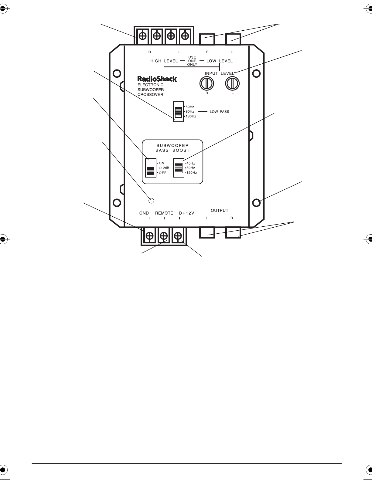
HIGH LEVEL Input Jacks
for Speaker-Level Outputs
LOW PASS
SUBWOOFER BASS
BOOST +12dB Bass
Enhancer
Power Indicator
LOW LEVEL Input
Jacks for Line-Level
Outputs
INPUT LEVEL
SUBWOOFER BASS
BOOST Bass Settings
Mounting
Hole
GND Ground Terminal
REMOTE Terminal
• does not interfere with the operation of
the vehicle
• is not directly in front of a heating vent
• allows drilling of mounting holes without
damaging other vehicle components
• allows convenient and safe routing of
wires
Connecting Input/Output
Note:
output connections (left output to left input,
and right output to right input).
Be sure to correctly match the input and
1. Disconnect the negative (–) cable from
your vehicle’s battery. This reduces the
possibility of damage to your crossover or
autosound system during installation.
Left and Right
OUTPUT Jacks
B+12V Power Terminal
Note:
After you complete the connections
and reconnect the battery cable, you
must reset all clock/memory devices in
your vehicle.
2. Connect your autosound system’s L (left)
and R (right) outputs to the crossover’s
(left) and R (right)
INPUT
jacks.This crossover has both speaker-level and line-level
inputs. Use either the
HIGH LEVEL
input terminals, but not both.
LOW LEVEL
• If your autosound system has line-
level outputs, use the two
LOW LEVEL
input jacks.
• If your autosound system does not
have line-level outputs, tap into the
wires for the existing speakers and use
the four
HIGH LEVEL
input jacks.
L
or
2
Page 3

3. Connect the autosound system speaker
wires to the crossover, carefully matching
polarity (L+ to
R– to
R–
).
, L– to L–, R+ to R+, and
L+
4. Connect the crossover’s L (left) and
(right)
OUTPUT
jacks to the L (left) and R
(right) inputs of the amplifier that drives
the subwoofer speakers.
1. Turn on your autosound system and
adjust the volume to a comfortable level.
The POWER indicator lights.
2. Play a cassette tape or CD that has a
R
wide dynamic range, or tune to a strong
FM station.
Notes:
Connecting Power
1. Ensure the negative (–) cable is disconnected from your vehicle’s battery.
2. Connect the crossover’s
terminal to a metal part of the vehicle’s
frame.
Caution:
Do not connect the ground wire
to a non-metallic (plastic) part, or to any
part insulated from the vehicle’s frame by
a non-metallic part.
3. Connect the crossover’s
terminal directly to the vehicle battery’s
+12 volt terminal.
4. Connect your autosound system’s
switched power lead wire (usually
orange) to the crossover’s
minal. This turns the crossover on and off
when you turn your autosound system on
and off.
(ground)
GND
B+12V
REMOTE
(power)
ter-
• If the sound from any speaker is distorted
or has static (or if there is no sound from
a speaker), turn off the power immediately, then check the wiring connections.
• If the system sounds with no distortion or
static, proceed to “Adjusting the Controls.”
ADJUSTING THE CONTROLS
Setting the Low Pass Crossover
Point
The
LOW PASS
three crossover points. All signals at or below
the selected frequency “cross over” to your
subwoofer speakers.
Slide the selector to
range of low-frequency sounds. Slide the selector to
90Hz
low-frequency sounds.
selector lets you set one of
to increase the
or
180Hz
to decrease the range of
50Hz
Note:
If your autosound system does not
have a switched power lead wire, connect
the crossover’s
REMOTE
point in your vehicle’s fuse box that provides 12-volt battery power only when the
ignition is set to ON or ACC.
5. Reconnect the cable to your vehicle battery’s negative (–) terminal.
Testing the Connections
Follow these steps to check your autosound
system before adjusting and mounting the
crossover.
terminal to a
Adjusting the Input Level
The input level controls let you adjust the
crossover to balance the subwoofer’s sound
level with the rest of your autosound system.
Turn your autosound system up to a normal
listening level, then use a flat-head screwdriver to rotate each
INPUT LEVEL
subwoofer is as loud as desired.
Caution:
If you use the
HIGH LEVEL
minals and turn your autosound system volume too high for the crossover, you could
damage the crossover. To reduce this possi-
3
control until the
input ter-
Page 4

bility, set the
midpoints.
INPUT LEVEL
controls past their
SPECIFICATIONS
Power Supply ............ 14.4 V DC Negative Ground
Adjusting the Subwoofer Bass
Boost
The
SUBWOOFER BASS BOOST
you boost 45, 80, or 120 Hz subwoofer output
by 12 dB to enhance low sounds when desired. Slide the
45 Hz/80 Hz/120 Hz
the appropriate position, then slide
. To return to the normal bass setting, set
ON
+12dB
to
OFF
.
controls let
selector to
+12dB
to
Mounting the Crossover
After you have correctly connected the crossover and set the controls, follow these steps to
mount the crossover.
Using the crossover mounting holes as a
guide, mark the positions for the mounting
screw holes at the desired location.
9
At each marked position, drill a
mm) hole.
/64-inch (3.57
Current Drain ............................................... 30 mA
Total Harmonic Distortion (THD) .... 0.04% at 20 Hz
Hum and Noise ................................ 150mV typical
Line-Level (Low) Input Impedance ......... 10 kOhms
Speaker-Level (High) Input Impedance . 100 Ohms
Operating Voltage .......................... 10.5 to 16V DC
S/N Ratio ..................................90 dB (A-Weighted)
Crossover Frequency:
Subwoofer Low Pass...... 50 HZ/90 Hz/180 Hz
Crossover Slope .............................. 12 dB/Octave
Channel Separation .......................... 60 dB Typical
Output Level ......... More Than 2V RMS at 1% THD
Dimensions (HWD) .......... 1
× 39/16 × 51/8 Inches
(26
× 92 × 131 mm)
Weight ........................................................ 10.2 oz
(290 g)
Specifications are typical; individual units might
vary. Specifications are subject to change and improvement without notice.
Caution:
Be careful not to drill into anything
behind the mounting surface.
Attach the crossover at the mounting location
using the supplied sheet metal screws, lockwashers, and washers.
This product is war ranted by RadioShack against ma nufacturing defects in materia l and
workmanship under normal use for one (1) year from the date of purchase from RadioShack
company-owned stores and authorized RadioShack franchisees and dealers. EXCEPT AS
PROVIDED HEREIN, RadioShack MAKES NO EXPRESS WARRANTIES AND ANY IMPLIED WARRANTIES, INCLUDING THOSE OF MERCHANTABILITY AND FITNESS FOR
A PARTICULAR PURPOSE, ARE LIMITED IN DURATION TO THE DURATION OF THE
WRITTEN LIMITED WARRANTIES CONTAINED HEREIN. EXCEPT AS PROVIDED
HEREIN, RadioShack SHALL HAVE NO LIABILITY OR RESPONSIBILITY TO CUSTOMER
OR ANY OTHER PERSON OR ENTITY WITH RESPECT TO ANY LIABILITY, LOSS OR
DAMAGE CAUSED DIRECTLY OR INDIRECTLY BY USE OR PERFORMANCE OF THE
PRODUCT OR ARISING OUT OF ANY BREACH OF THIS WARRANTY, INCLUDING, BUT
NOT LIMITED TO, ANY DAMAGES RESULTING FROM INCONVENIENCE, LOSS OF
TIME, DATA, PROPERTY, REVENUE, OR PROFIT OR ANY INDIRECT, SPECIAL, INCIDENTAL, OR CONSEQUENTIAL DAMAGES, EVEN IF RadioShack HAS BEEN ADVISED
OF THE POSSIBILITY OF SUCH DAMAGES.
Some states do not al low limi tati ons on ho w long an impli ed warr anty las ts or t he exc lusion
or limitation of incidental or consequential damages, so the above limitations or exclusions
may not apply to you.
In the event of a product defect during the warranty period, take the product and the RadioShack sales receipt as proof of purchase date to any RadioShack store. RadioShack will,
at its option, unless otherwise provided by law: (a) correct the defect by product repair without charge for parts and labor; (b) replace the produ ct with one of th e same or simi lar design ;
or (c) refund the purchase pri ce. Al l repl aced parts and p roduc ts, an d prod ucts on w hich a re fund is made, become the property of RadioShack. New or reconditioned parts and products
may be used in the performance of warranty service. Repaired or replaced parts and products are warrant ed fo r the re main der o f the or igin al wa rran ty p erio d. You will be cha rged for
repair or replac ement of the product made after the expiration of the warranty period.
This warranty does not cover: (a) damage or failure caused by or attributable to acts of God,
abuse, accident, misu se , i mp rop er or abnormal usage, fail ure to fol lo w in stru c tions, improper
installation or maintenance, alteration, lightning or other incidence of excess voltage or current; (b) any repairs other than those provided by a RadioShack Authorized Service Facility;
(c) consumables such as fuses or batteries; (d) cosmetic damage; (e) transportation, shipping or insurance costs; or (f) costs of product removal, installation, set-up service adjustment or reinstallation.
This warranty give s you s pecif ic le gal ri ght s, an d you may also have other righ ts w hich va ry
from state to state.
RadioShack Customer Relations, 200 Taylor Street, 6th Floor, Fort Worth, TX 76102
Limited One-Year Warranty
We Service What We Sell
12/99
05A00
12-2012 Printed in China
 Loading...