

Quadra-Fire MTVERNON-AE-CSB, MTVERNON-AE-PBK, MTVERNON-AE-PFT, MTVERNON-AE-PDB, MTVERNON-AE-MBK Installation Manual
...
Installation Manual
Installation & Appliance Set-Up
INSTALLER: Leave this manual with party responsible for use and operation.
OWNER: Retain this manual for future reference.
NOTICE: DO NOT DISCARD THIS MANUAL
WARNING
If the information in these instruc-
MT. VERNON PELLET STOVE
ADVANCED ENERGY (AE)
Model(s):
MTVERNON-AE-CSB
MTVERNON-AE-MBK
• Do not store or use gasoline or other fl am-
mable vapors and liquids in the vicinity of
this or any other appliance.
tions is not followed exactly, a
fi re may result causing property
damage, personal injury, or death.
MTVERNON-AE-PBK
MTVERNON-AE-PDB
MTVERNON-AE-PFT
MTVERNON-AE-PMH
US
Portland
Oregon USA
Tested and
O-T L
Listed by
C
OMNI-Test Laboratories, Inc.
061-S-68-6
CAUTION
Tested and approved for wood pellets, shelled fi eld
corn, wheat and black oil sunfl ower seeds. Burning of
any other type of fuel voids your warranty.
• Do not overfi re - If heater or chimney con-
nector glows, you are overfi ring. Overfi ring
will void your warranty.
• Comply with all minimum clearances to
combustibles as specifi ed. Failure to
comply may cause house fi re.
WARNING
HOT SURFACES!
Glass and other surfaces are hot
during operation AND cool down.
Hot glass will cause burns.
• Do not touch glass until it is cooled
• NEVER allow children to touch glass
• Keep children away
• CAREFULLY SUPERVISE children in same room as
fi replace.
• Alert children and adults to hazards of high temperatures
• High temperatures may ignite clothing or other
fl ammable materials.
• Keep clothing, furniture, draperies and other fl ammable
materials away.
CAUTION
Check building codes prior to installation.
• Installation MUST comply with local, regional, state and national codes and regulations.
• Consult local building, fi re offi cials or authorities having juris-
diction about restrictions, installation inspection, and permits.
1 7034-277E May 5, 2015
NOTE
To obtain a French translation of this manual, please contact
your dealer or visit www.quadrafi re.com
Pour obtenir une traduction française de ce manuel, s’il vous
plaît contacter votre revendeur ou visitez www.quadrafi re.com
MT. VERNON AE
Safety Alert Key:
• DANGER! Indicates a hazardous situation which, if not avoided will result in death or serious injury.
• WARNING! Indicates a hazardous situation which, if not avoided may result in death or serious injury.
• CAUTION! Indicates a hazardous situation which, if not avoided, may result in minor or moderate injury.
• NOTICE: Indicates practices which may cause damage to the appliance or to property.
TABLE OF CONTENTS
1 Important Safety Information .............3
A. Appliance Certifi cation ......................................................3
B. BTU & Effi ciency Specifi cations........................................3
C. Glass Specifi cations .........................................................3
D. Electrical Rating................................................................3
E. Mobile Home Approved .................................................... 3
2 Getting Started ....................................4
A. Design, Installation & Location Considerations ..........................4
B. Thermostat Wall Control Location......................................5
C. Tools And Supplies Needed ..............................................5
D. Inspect Appliance and Components .................................5
E. Install Checklist ..................................................................6
3 Dimensions and Clearances ..............7
A. Appliance Dimensions ......................................................7
B. Clearances to Combustibles (UL and ULC) .......................8
C. Hearth Pad Requirements (UL and ULC) ..........................8
4 Vent Information ..................................9
A. Venting Termination Minimum Requirements ...................9
B. Avoiding Smoke and Odors ...............................................10
C. Negative Pressure .............................................................11
D. Draft ........ ..........................................................................11
E. Chimney and Exhaust Connection ...................................11
F. Equivalent Feet of Pipe .....................................................12
G. Pipe Selection Chart .........................................................12
5 Venting Systems ...............................13
A. Alcove ..............................................................................13
B. Through The Wall .............................................................14
C. Vertical into Existing Class A Chimney .............................15
D. Through The Wall & Vertical - Exterior ..............................15
E. Vertical - Interior - Typical Installation ................................15
F. Masonry.............................................................................16
G. Alternate Masonry ............................................................16
6 Appliance Set-Up ..............................17
A. Leg Leveling System .......................................................17
B. Outside Air Kit Instructions ................................................17
C. Top Vent Adapter Installation ............................................18
D. Rear Vent & Rear Vent to Top Vent Adapter Installation ....18
E. Optional Log Set Placement Instructions ..........................19
F. Wall Control Thermostat Installation .................................20
7 Mobile Home Installation ..................21
8 Accessory List ..................................22
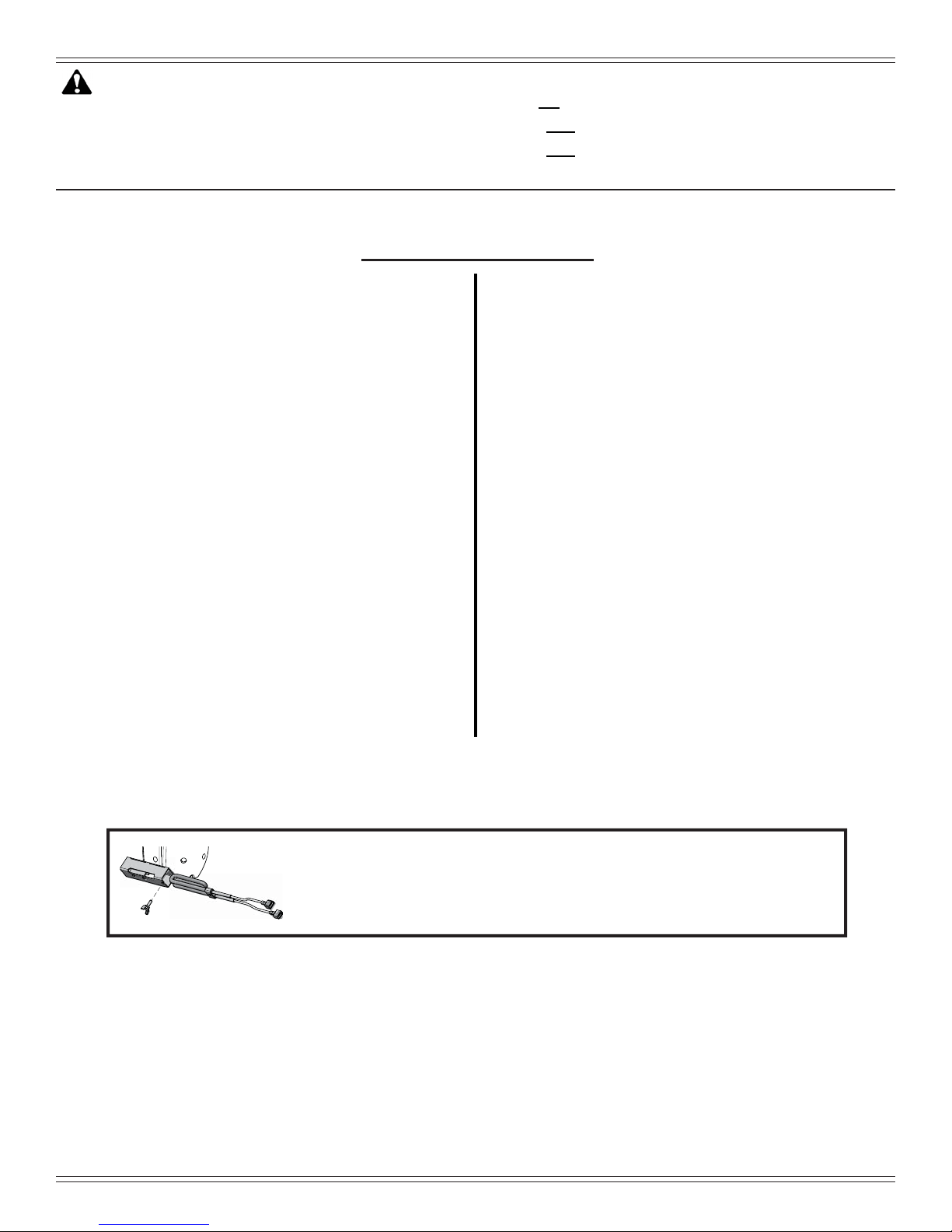
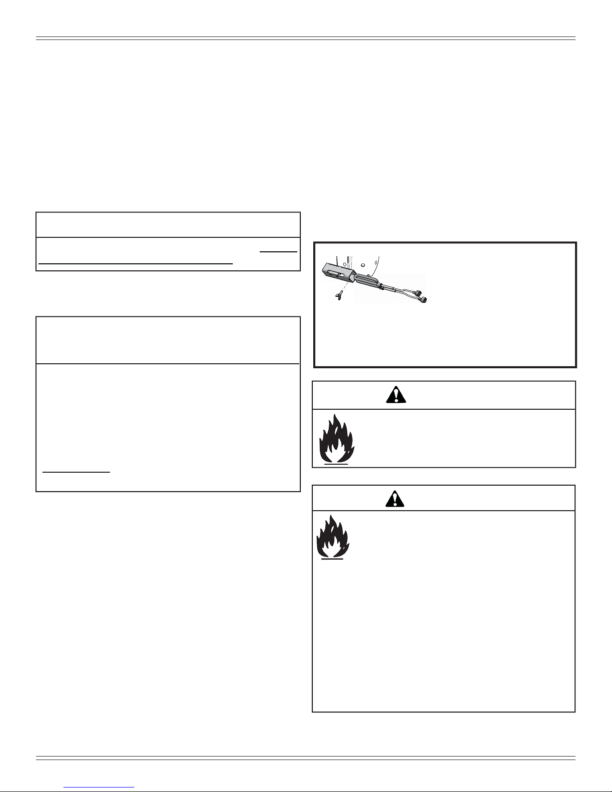
300 Watt Igniters come installed in brand new Mt. Vernon AE
units and are for pellet fuel only. The 380 Watt Igniter is required
for burning multi-grain fuels and is included in the component
pack. Multi-fuels include, corn, sunfl ower seeds, and wheat.
2 7034-277E May 5, 2015
1 Important Safety Information
MT. VERNON AE
A. Appliance Certifi cation
Model Mt. Vernon Pellet Stove
Laboratory OMNI Test Laboratories, Inc.
Report No. 061-S-68-6
Type Solid Fuel Room Heater/Pellet Fuel
Burning Type
Standard ASTM E1509-04, ULC S627-00 and
ULC/ORD-C1482-M1990 Room Heater
Pellet Fuel Burning type and (UM)
84-HUD, Mobile Home Approved.
FCC Complies with Part 15 of FCC Rules.
Operation is subject to the following
two conditions: (1) this device may not
cause harmful interference, and (2) this
device must accept any interference
received, including interference that may
cause undesired operation.
NOTICE: This installation must conform with local codes. In
the absence of local codes you must comply with the ASTM
E1509-04, ULC S627-00, (UM) 84-HUD and ULC/ORDC-1482.
The Quadra-Fire Mt. Vernon AE Pellet Heater meets the U.S.
Environmental Protection Agency’ s emission limits for pellet
heaters sold after May 15, 2015.
This pellet heater needs periodic inspection and repair for
proper operation. It is against federal regulations to operate
this pellet heater in a manner inconsistent with operating
instructions in this manual.
B. BTU & Effi ciency Specifi cations
EPA Certifi cation #: 970-14
EPA Certifi ed Emissions: 1.7 grams per hour
*LHV Tested Effi ciency: 76.9 %
**HHV Tested Effi ciency: 71.2 %
***EPA BTU Output: 12,500 to 40,200 / hr.
****BTU Input: 16,800 to 53,300 / hr.
Vent Size: 3 or 4 inches, “L” or “PL”
Hopper Capacity: 75 lbs.
Fuel Wood Pellets
* Weighted average LHV effi ciency using data collected during
EPA emissions test.
**Weighted average HHV effi ciency using data collected during
EPA emissions test.
***A range of BTU outputs based on EPA Default Effi ciency and
the burn rates from the low and high EPA tests.
****Based on the maximum feed rate per hour multiplied by
approximately 8600 BTU’s which is the average BTU’s from a
pound of pellets.
C. Glass Specifi cations
This stove is equipped with 5mm ceramic glass. Replace
glass only with 5mm ceramic glass. Please contact your
dealer for replacement glass.
D. Electrical Rating
115 VAC, 60 Hz, Start 5 Amps, Run 1.25 Amps
E. Mobile Home Approved
• This appliance is approved for mobile home installations when not installed in a sleeping room and when
an outside combustion air inlet is provided.
• The structural integrity of the mobile home fl oor, ceil-
ing, and walls must be maintained.
• The appliance must be properly grounded to the
frame of the mobile home and use only Listed pellet
vent Class “L” or “PL” connector pipe.
• Outside Air Kit, part OAK-ACC must be installed in a
mobile home installation.
WARNING
Fire Risk.
Hearth & Home Technologies disclaims any
responsibility for, and the warranty will be voided by,
the following actions:
• Installation and use of any damaged appliance.
• Modifi cation of the appliance.
• Installation other than as instructed by Hearth & Home
Technologies.
• Installation and/or use of any component part not approved by
Hearth & Home Technologies.
• Operating appliance without fully assembling all components.
• Operating appliance without legs attached (if supplied with unit).
• Do NOT Overfi re - If appliance or chimney connector glows,
you are overfi ring.
Any such action that may cause a fi re hazard.
Improper installation, adjustment, alteration, service or
maintenance can cause injury or property damage.
For assistance or additional information, consult a qualifi ed
installer, service agency or your dealer.
NOTE: Hearth & Home Technologies, manufacturer of
this appliance, reserves the right to alter its products, their
specifi cations and/or price without notice.
Quadra-Fire is a registered trademark of Hearth & Home
Technologies.
May 5, 2015 7034-277E 3
MT. VERNON AE
2 Getting Started
Install Guide
A. Design, Installation & Location Considerations
1. Appliance Location
NOTICE: Check building codes prior to installation.
• Installation MUST comply with local, regional, state and
national codes and regulations.
• Consult insurance carrier, local building inspector, fi re
offi cials or authorities having jurisdiction over restrictions,
installation inspection and permits.
It is a good idea to plan your installation on paper, using exact
measurements for clearances and fl oor protection, before
actually beginning the installation. Location of the appliance
and chimney will affect performance.
Consideration must be given to:
• Safety, convenience, traffi c fl ow
• Placement of the chimney and chimney connector and to
Since pellet exhaust can contain ash, soot or sparks, you
must consider the location of:
• Windows
• Air Intakes
• Air Conditioner
• Overhang, soffi ts, porch roofs, adjacent walls
• Landscaping, vegetation
• Horizontal or vertical vent termination
2. Floor Support
The supporting fl oor under the appliance must be able to
handle the weight of the appliance, fuel load and the weight
of the chimney.
Ensure that your fl oor will support these weights prior to
installation. Add suffi cient additional support to meet this
weight requirement prior to installation. The weight of the
appliance is 429 lbs.
minimize the use of chimney offsets.
• Place the appliance where there will be a clear passage
for a Listed chimney through the ceiling and roof (vertical)
or through exterior wall (horizontal).
• Installing the required outside air kit will affect the location
of the vent termination.
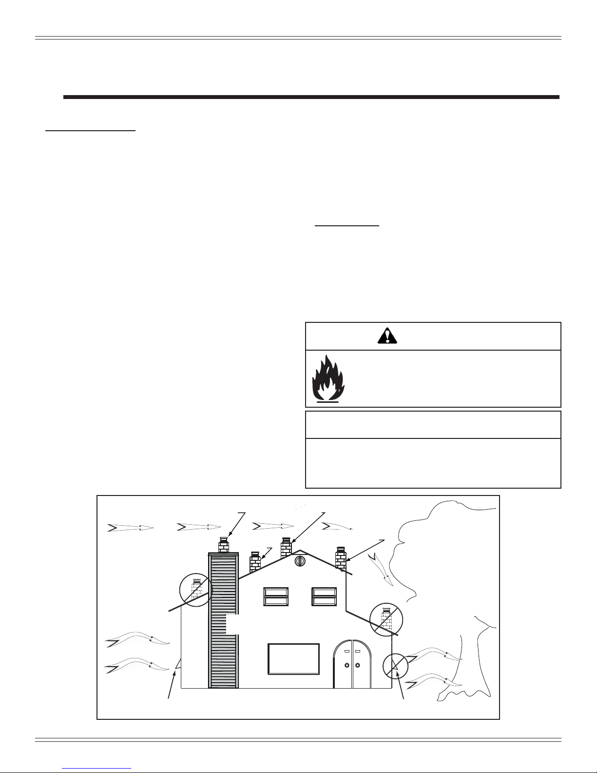
When locating vent and venting termination, the ideal location is to vent above roof line when possible. This minimizes
the affects of wind loading.
WARNING
Risk of Fire
Damaged parts could impair safe operation. Do
NOT install damaged, incomplete or substitute
components.
CAUTION
If burning shelled fi eld corn, you must use approved vent-
ing specifi cally designed for corn to prevent corrosion
or degradation. Follow the instructions from the venting
manufacturer.
Location NOT recommended:
• Not the highest point of the roof
• Wind loading possible
Windward
Recommended:
Outside Air Intake
on windward side
Figure 4.1
4 7034-277E May 5, 2015
Recommended Location:
• Above peak
Marginal Location:
• Below peak
Recommended:
• Insulated exterior chase
in cooler climates
Recommended Location:
• Above peak
• Inside heated space
Multi-level Roofs
Marginal Location:
• Wind loading possible
Location NOT recommended:
• Too close to tree
• Below adjacent structure
• Lower roof line
• Avoid outside wall
Leeward
NOT recommended:
Outside Air Intake
on leeward side
MT. VERNON AE
B. Thermostat Wall Control Location
The thermostat wall control’s location will have some affect
on the appliance’s operation.
• Maximum wire length from appliance is 100 feet (30.48m)
continuous unspliced wire. Recommended 20 gauge wire,
solid copper .
• When located close to the appliance, it may require a
slightly higher temperature setting to keep the rest of the
house comfortable.
• When located in an adjacent room or on a different fl oor
level, you will notice higher temperatures near the appliance.
CAUTION
The wall control is an integral part of the appliance. No other
wall control or thermostat can be substituted.
C. Tools And Supplies Needed
Tools and building supplies normally required
for installation, unless installing into an existing
masonry fi replace:
Reciprocating Saw Channel Locks
Hammer Phillips Screwdriver
Tape Measure Plumb Line
1/4” Self-Tapping Screws Framing Material
Hi-temp Caulking Material Gloves
Safety Glasses Framing Square
Electric Drill & Bits (1/4”) Level
May also need:
Vent Support Straps Venting Paint
D. Inspect Appliance and Components
• Open the appliance and remove all the parts and articles
packed inside the Component Pack. Inspect all the parts
and glass for shipping damage.
• Report to your dealer any parts damaged in shipment.
•
All labels have been removed from the glass door.
•
Plated surfaces have been wiped clean with a soft cloth,
if applicable.
• Read all the instructions before starting the installation.
Follow these instructions carefully during the
installation to ensure maximum safety and benefi t.
• Follow pipe manufacturer instructions for installation
and air clearance requirements.
300 Watt Igniters come
installed in brand new
Mt. Vernon AE units and
are for pellet fuel only.
The 380 Watt Igniter is
required for burning multi-grain fuels and is
included in the component pack. Multi-fuels
include, corn, sunfl ower seeds, and wheat.
WARNING
Risk of Fire
Damaged parts could impair safe operation.
Do NOT install damaged, incomplete or
substitute components.
May 5, 2015 7034-277E 5
WARNING
Hearth & Home Technologies disclaims any
responsibility for, and the warranty will be voided
by, the following actions:
• Installation & use of any damaged appliance.
• Modifi cation of the appliance.
• Installation other than as instructed by Hearth & Home
Technologies.
• Installation and/or use of any component part not
approved by Hearth & Home Technologies.
• Operating appliance without fully assembling all
components.
• Operating appliance without legs attached (if supplied
with unit).
• Do NOT Overfi re
Or any such action that may cause a fi re hazard.

MT. VERNON AE
E. Install Checklist
ATTENTION INSTALLER:
Follow this Standard Work Checklist
This standard work checklist is to be used by the installer in conjunction with, not instead of, the instructions contained in this installation manual.
Customer:
Date Installed:
Lot/Address:
Location of Fireplace:
Installer:
Dealer/ Distributor Phone #:
Serial #:
Model (circle one): MTVERNON-AE-CSB MTVERNON-AE-MBK MTVERNON-AE-PBK MTVERNON-AE-PDB
MTVERNON-AE-PFT MTVERNON-AE-PMH
WARNING! Risk of Fire or Explosion! Failure to install fi replace according to these instructions can lead to a fi re or explosion.
Appliance Install
Verifi ed clearances to combustibles. (Pg. 8)
Fireplace is leveled and liner is secured to appliance. (Pg. 18)
Hearth extension size/height decided. (Pg. 22)
Outside air kit installed. (Pg. 15)
Floor protection requirements have been met.
The masonry chimney is inspected by a professional and is clean or the
factory built metal chimney is installed according to the manufacturer’s
instructions and clearances.
YES IF NO, WHY?
Chimney Section 4 (Pg. 10)
Chimney confi guration complies with diagrams.
Chimney installed, locked and secured in place with proper clearance.
Chimney meets the minimum height requirements.
Roof fl ashing installed and sealed.
Terminations installed and sealed.
Clearances Section 3 (Pg. 7)
Combustible materials not installed in non-combustible areas.
Verifi ed all clearances meet installation manual requirements.
Mantels and wall projections comply with installation manual requirements.
Protective hearth strips and hearth extension installed per manual requirements.
Appliance Setup Section 5 (Pg. 15)
All packaging and protective materials removed.
Firebrick, baffl e and ceramic blanket installed correctly.
All labels have been removed from the door.
All packaging materials are removed from inside/under the fi replace.
Manual bag and all of its contents are removed from inside/under the fi replace
and given to the party responsible for use and operation.
Hearth & Home Technologies recommends the following:
• Photographing the installation and copying this checklist for your fi le.
• That this checklist remain visible at all times on the fi replace until the installation is complete.
Comments: Further description of the issues, who is responsible (Installer/Builder/Other Trades, etc.) and corrective action needed:
Comments communicated to party responsible by on
(Builder/Gen. Contractor) (Installer) (Date)
6 7034-277E May 5, 2015
Part # 4017-254 • Rev B • 01/29/13

3 Dimensions and Clearances
A. Appliance Dimensions
MT. VERNON AE
5-13/16 in.
(147mm)
2-9/16 in.
(65mm)
14-1/16 in.
(357mm)
C
L
3-13/16 in.
(97mm)
Figure 7.1 - Top View with Top Vent Adapter and 3 to 6
in (76-152mm) Adapter
31-1/6 in.
(788mm)
29-3/6 in.
(741mm)
Figure 7.2 - Side View with Top Vent Adapter and 3 to
6 in (76-152mm) Offset Adapter.
10-3/8 in.
(264mm)
C
L
28-1/8 in. (714mm)
32-5/16 in.
(821mm)
28-7/16 in.
(722mm)
Figure 7.4 - Front View
May 5, 2015 7034-277E 7
Figure 7.3 - Top View
Figure 7.5 - Side View
29-1/16 in. (738mm)
26-7/8 in. (683mm)
18-1/2 in. (470mm)
20 in.
(508mm)
C
L
19-9/16 in.
(497mm)
MT. VERNON AE
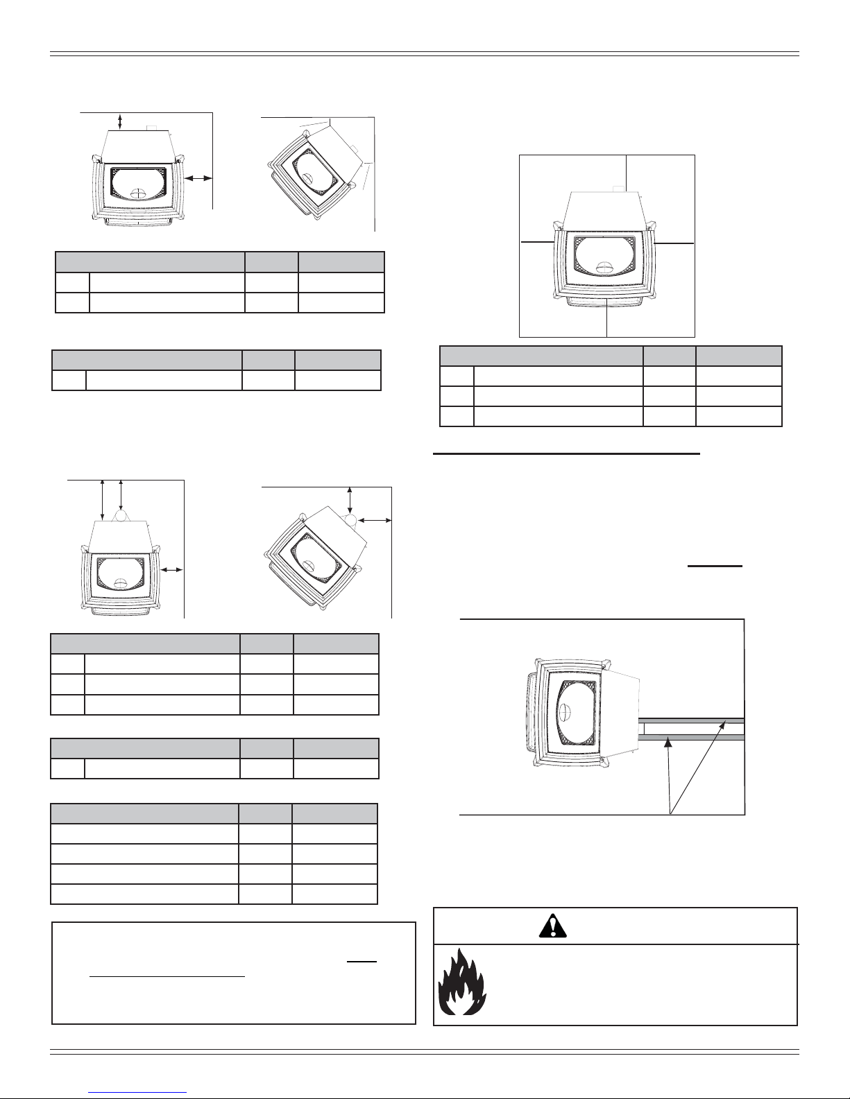
B. Clearances to Combustibles (UL and ULC)
A
B
Straight Back Against Wall Inches Millimeters
A Back Wall to Appliance 2 51
B Side Wall to Appliance 6 152
Corner Installation Inches Millimeters
C Walls to Appliance 2 51
Installations with:
3 to 3 inch Top Vent Adapter and
3 to 6 inch Offset Adapter Kit
F
D
E
C
C
G
G
C. Hearth Pad Requirements (UL and ULC)
Use a non-combustible fl oor protector, extending beneath
appliance and to the front, sides and rear as indicated. Measure front distance “M” from the surface of the glass door.
L*
K
K
M
Hearth Pad Requirements Inches Millimeters
K Sides 2 51
L* Back 2 51
M Front 6 152
*L Exception for Horizontal Installations:
USA INSTALLATIONS: A
tion is recommended extending beneath the fl ue pipe when
installed with horizontal venting or under the Top Vent
Adapter with vertical installation.
CANADA INSTALLATIONS: A
tection extending beneath the fl ue pipe is required with hor-
izontal venting or under the Top Vent Adapter with vertical
installation.
non-combustible fl oor protec-
non-combustible fl oor pro-
Vertical Installation Inches Millimeters
D Back Wall to Flue Pipe 3 76
E Side Wall to Appliance 6 152
F Back Wall to Appliance 8 203
Corner Installation Inches Millimeters
G Side Wall to Flue Pipe 3 76
Alcove Installation Inches Millimeters
Minimum Alcove Height 43 1092
Minimum Alcove Side Wall 6 152
Minimum Alcove Width 40 1016
Maximum Alcove Depth 36 914
NOTE:
• Illustrations refl ect typical installations and are FOR
DESIGN PURPOSES ONLY.
• Illustrations/diagrams are not drawn to scale.
• Actual installation may vary due to individual design
preference.
Must extend 2 inches (51mm) beyond each
side of pipe (shaded area)
WARNING
Fire Risk.
Comply with all minimum clearances to combustibles
as specifi ed.
Failure to comply may cause house fi re.
8 7034-277E May 5, 2015
 Loading...