

Quadra-Fire 4300 Series, 43M-ACC-MBK, 43ST-ACC Owner's Manual
Advanced Combustion Control (ACC)
Step Top Uni-Body Model
(Pedestal Model Shown)
4300 WOOD STOVE SERIES
Owner’s Manual
Installation and Operation
Models:
43M-ACC-MBK
43ST-ACC
Millennium Model
R
US
Portland
Oregon USA
Tested and
O-T L
Listed by
C
OMNI-Test Laboratories, Inc.
DO NOT DISCARD THIS MANUAL
•
Important operating
and maintenance instructions included.
• Read, understand and
follow these instructions
for safe installation and
operation.
WARNING
If the information in these instructions is not followed exactly, a fi re
may result causing property damage, personal injury, or death.
• Do not store or use gasoline or other fl am-
mable vapors and liquids in the vicinity of
this or any other appliance.
• Do not overfi re - If heater or chimney con-
nector glows, you are overfi ring. Overfi ring
will void your warranty.
• Comply with all minimum clearances to
combustibles as specifi ed. Failure to
comply may cause house fi re.
CAUTION
Hot glass will cause burns.
• Do not touch glass until it is cooled
• NEVER allow children to touch glass
• Keep children away
• CAREFULLY SUPERVISE children in same room
• Alert children and adults to hazards of high
High temperatures may ignite clothing or other
fl ammable materials.
• Keep clothing, furniture, draperies and other
• Leave this manual with
party responsible for
use and operation.
WARNING
HOT SURFACES!
Glass and other surfaces are
hot during operation AND
cool down.
as fi replace.
temperatures.
fl ammable materials away.
DO NOT
DISCARD
Installation and service of this appliance should
be performed by qualifi ed personnel. Hearth &
Home Technologies recommends NFI certifi ed
professionals, or technicians supervised by an
NFI certifi ed professional.
www.quadrafi re.com
7037-135G
WARNING
Fire Risk.
For use with solid wood fuel only.
Other fuels may overfi re and generate
poisonous gases (i.e. carbon monoxide).
August 31, 2010
4300 Wood Stove Series (ACC)
R
and Welcome to the Quadra-Fire Family!
Hearth & Home Technologies welcomes you to our tradition of excellence! In choosing a Quadra-Fire appliance,
you have our assurance of commitment to quality , durability, and performance.
This commitment begins with our research of the market,
including ‘Voice of the Customer’ contacts, ensuring we
make products that will satisfy your needs. Our Research
and Development facility then employs the world’s most
our stoves, inserts and fi replaces. And yet we are old-fash-
ioned when it comes to craftsmanship. Each unit is meticulously fabricated and surfaces are hand-fi nished for lasting
beauty and enjoyment. Our pledge to quality is completed
as each model undergoes a quality control inspection.
We wish you and your family many years of enjoyment in
the warmth and comfort of your hearth appliance. Thank
you for choosing Quadra-Fire.
advanced technology to achieve the optimum operation of
NOTE: Clearances may only be reduced by means
approved by the regulatory authority having jurisdiction
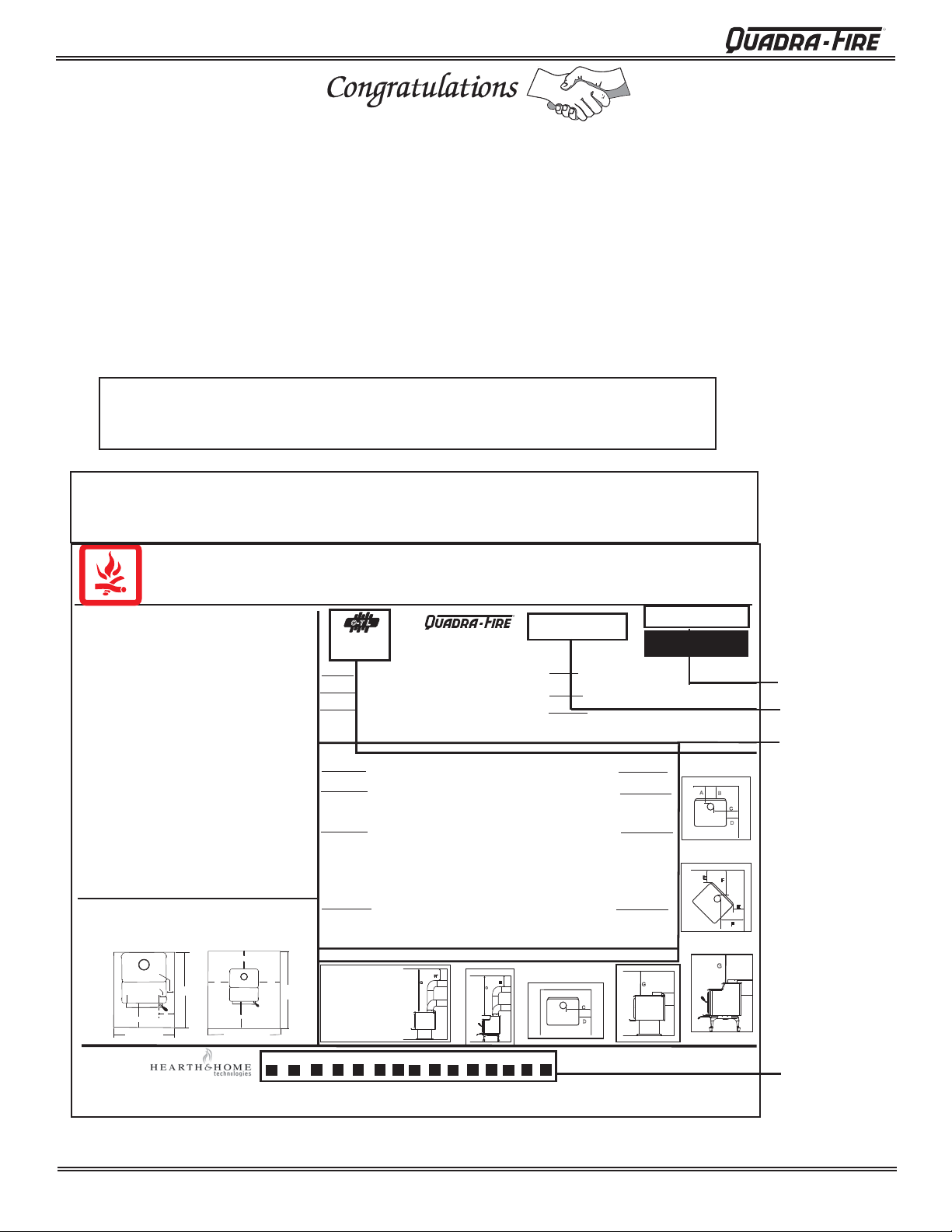
SAMPLE OF SERIAL NUMBER / SAFETY LABEL
LOCATION: BACK OF APPLIANCE
Tested and
Listed by
OMNI-Test Laboratories, Inc.
SINGLE WALL: Six inch (6 inches) (152mm) diameter, minimum 24 MSG black or blued steel connector
pipe, with a listed factory-built UL103HT* Class "A" chimney, suitable for use with solid fuels, or a
masonry chimney, and the referenced clearances.
DOUBLE WALL: Six inch (6 inches) (152mm) diameter, listed double wall air insulated connector pipe
with listed factory-built UL103HT* Class "A" chimney, or a masonry chimney and the referenced
clearances
MOBILE HOME: Use double wall pipe by Dura-Vent DVL, Selkirk Metalbestos DS or Security DL double
wall connector pipe. Must be equipped with a spark arrestor. Apply double wall clearances below when
installing unit.
MINIMUM CLEARANCES TO COMBUSTIBLE MATERIALS: In Inches & (Millimeters)
NOTE: All "A" , "C" and "F" Dimensions are to inside diameter of the flue collar.
INSTALLATION: FULL VERTICAL OR HORIZONTAL WITH
INSTALLATION: ENTIÈREMENT VERTICALE OU HORIZONTALE AVEC 609mm VERTICAL
SINGLE WALL PIPE A B C D E F G H
Flat Top Model 18 (457) 15.5 (394) 26 (660) 17 (432) 10 (255) 18.5 (470) 52.5 (1334) 18 (457)*
Step Top Model 12 (305) 8.5 (216) 23 (584) 13 (330) 2 (51) 13 (330) 50.5 (1283) 18 (457)*
DOUBLE WALL PIPE
Flat Top Model 13 (330) 10.5 (267) 24.5 (622) 15 (381) 10 (255) 18.5 (470) 52.5 (1334) 10 (254)
Step Top Model 10 (254) 6.5 (165) 23 (584) 13 (330) 2 (51) 13 (330) 50.5 (1283) 5 (127)
INSTALLATION: 90o ELBOW OFF TOP OF STOVE THROUGH BACKWALL
INSTALLATION: 90o DU COURBURE AU DESSUS DE HAUT DU PO
DOUBLE WALL PIPE
Flat Top Model 8.5 (216) 6 (152) 24.5 (622) 15 (381) 10 (254) 18.5 (470) 52.5 (1334) 18 (457)*
Step Top Model 7.5 (191) 4 (102) 19 (483) 9 (229) 2 (51) 13 (330) 50.5 (1283) 18 (457)*
INSTALLATION: ALCOVE -
must be equipped with a spark arrestor.) Maximum depth of Alcove shall be no more than 48 inches (1220mm) with a minimum height of 45.5 inches (1156mm) to top of unit, and the referenced clearances. Please
refer to the clearances below for minimum Alcove height requirement to top of unit.
INSTALLATION: ALCÔVE - De six (6 inches) (152mm) de diamètre, le connecteur du conduit d'air isolé pour mur double avec une cheminée bâtit en usine UL103HT de Classe "A", ou une cheminée de briques. (Les maisons
mobiles doivent être équipées d'un arrêt d'étincelle). La profondeur maximum de l'alcôve ne doit pas être de plus de 48 inches (1220mm) avec une hauteur minimum de 45.5 inches (1156mm) du haut de l'appareil, et des espaces
libres alloués. Référez vous s'il vous plaît aux dégagements repirs ci-dessus pour la hauteru minimum requise entre le dessus ole l'appareil et l'alcove (de la chimineé).
DOUBLE WALL PIPE
Flat Top Model 13 (330) 10.5 (267) 24.5 (622) 15 (381) N/A N/A 52.5 (1334) N/A
Step Top Model
*In Canada must comply with Standard CAN/ULC-S629-M87 for the 650oC Factory-built chimney.
*Au Canada doit conformer a CAN/ULC-S629-M87 la norme pour 650oC cheminée bâtit en usine.
NFPA 211
*
90o OFF TOP
UP & OUT CEILING CLEARANCE
1334mm
ESPACE LIBRE DU DESSUS DE
(52-1/2")
SAMPLE
L'APPAREIL AU PLAFOND AVEC 90
minimum
DE COURBURE
STOVE TO CEILING CLEARANCE
ESPACE LIBRE DU POÊLE AU
PLAFOND
Portland
O-T L
Oregon USA
C
Report / Rapport
#061-S-67-7
TESTED TO:/ TESTÉ À:
UL 1482, ULC S627-00
VENT SPECIFICATIONS:
MINIMUM
Six inch (6 inches) (152mm) diameter listed DOUBLE WALL air insulated connector pipe with UL103 HT* listed factory-built Class "A" chimney, or a masonry chimney. (Mobile Home
10 (254) 6.5 (165) 23 (584) 13 (330) N/A N/A 37 (940) N/A
MINIMUM
CLEARANCES - NOT TESTED
H*
G G
R
4300 ACC Series
MUR SIMPLE: De six (6 inches) (152mm) de diamètre le connecteur de conduit de minimum
d'acier noir ou bleu de minimum de 24MSG, avec une cheminée bâtit en usine UL103HT* de
Classe "A", adéquate pour usage avec les combustions solides, ou une cheminée de briques,
avec espaces libres référés.
MUR DOUBLE: De six (6 inches) (152mm) de diamètre, le connecteur du conduit d'air isolé
pour mur double avec une cheminée bâtit en usine UL103HT* de Classe "A:, ou une cheminée
de briques, avec espaces libres alloués.
MAISON MOBILE: Utiliser un conduit de mur double par Dura-Vent DVL, Selkirk Metalbestos
DS ou Security DL. Doit être équipé d'un arrêt d'étincelle. Utiliser les espaces libres pour mur
double comme mentionné ci-bas.
NOTE: Toutes les dimensions "A", "C", et "F" sont à partir du diamètre intérieur de l'entrée du conduit.
2 FOOT VERTICAL OFF STOVE TOP
MINIMUM
DU HAUT DU POÊLE
Ê
LE A TRAVERS LE MUR ARRIÈRE
ALCOVE TOP VIEW /
VUE DU HAUT DE L'ALCÔVE
H
G
Made in U.S.A./Fait Aux États-Unis
SPÉCIFICATIONS DE LA VENTILATION:
ESPACES LIBRES MINIMUM DES MATÉRIAUX COMBUSTIBLES:En Pouces & (millimètres)
C
D
U.S. ENVIRONMENTAL PROTECTION AGENCY - Certified to
comply with July 1990 particulate emission standards.
CAUTION
ATTENTION:
LISTED ROOM HEATER, SOLID FUEL TYPE.
ALSO FOR USE IN MOBILE HOMES. (UM) 84 HUD
PREVENT HOUSE FIRES
I
nstall and use only in accordance with
manufacturer's installation and operating
instructions. Contact local building or fire
officials about restrictions and installation
inspections in your area. Do not obstruct the
space beneath heater.
WARNING - For Mobile Homes: Do not
install in a sleeping room. An outside
combustion air inlet must be provided and
unrestricted while unit is in use. The structural
integrity of the mobile home floor, ceiling and
walls must be maintained. The stove needs to
be properly grounded to the frame of the mobile
home. Components required for mobile home
installation: Outside Air Kit, Part Number
OAK-ACC.
Refer to manufacturer's instructions and
local codes for precautions required for passing
chimney through a combustible wall or ceiling
and maximum offsets.
nspect and clean chimney frequently - Under
I
Certain Conditions of Use, Creosote Buildup May
Occur Rapidly.
Do not connect this unit to a chimney serving another
appliance.
Optional Components: Optional Blower, Part
BK-ACC.
Electrical Rating: 115 VAC, 1.2 Amps, 60 Hz.
Route power cord away from unit. Do not route
cord under or in front of appliance.
DANGER: Risk of electrical shock.
Disconnect power supply before servicing.
Replace glass only with 5mm ceramic available
from your dealer.
Do not use grate or elevate fire. Build wood fire
directly on hearth.
Do not overfire - if heater or chimney
connector glows, you are overfiring.
Operate only with the fuel loading door
FLOOR PROTECTION
Floor protector must be a 3/8 inch min. thickness,
non-combustible material or equivalent, extending
beneath heater and to front/sides/rear as indicated on
the diagram below. Exception: Non-combustible floor
protections must extend beneath the flue pipe when
installed with horizontal venting and extend 2 inches
(51mm) beyond each side.
Fuel loading door
16" from glass
31-5/8" minimum
Step Top & Millennium
Manufactured by:
Fabriqué par:
APPAREIL DE CHAUFFAGE DE PIÈCE, DE TYPE DE
COMBUSTIBLE SOLIDE, POUR USAGE DANS LES
MAISONS MOBILES. (UM) 84 HUD. "Pour Usage
Avec Bois Solide Seulement"
PRÉVENTION DES FEUX DE MAISON
Installez et utilisez en accord avec les instructions
d'installation et d'opération du fabricant. Contactez le
bureau de la construction ou le bureau des incendies au
sujet des restrictions et des inspections d'installation dans
votre voisinage. Ne pas obstruez l'espace en dessous de
l'appareil.
AVIS - Pour Les Maisons Mobiles: Ne pas installer dans
une chambre à coucher. Un tuyau extérieur de combustion
d'air doit être installé et ne doit pas être obstrué lorsque
l'appareil est en usage. La structure intégrale du plancher,
du plafond et des murs de la maison mobile doit être
maintenue intacte. L'appareil de chauffage doit être fixé à
la charpente de la maison mobile. Les composants requis
pour l'installation des maisons mobiles: Assemblage d'air
extérieur, Numéro de Pièce OAK-ACC..
Référez vous aux instructions du fabricant et des codes
locaux pour les précautions requises pour passer une
cheminée à travers un mur ou un plafond combustibles, et les
compensations maximums.
In
certaines conditions, il se peut que la créosote s'accumule
rapidement.
Ne pas connecter cet appareil à une cheminée servant un
autre appareil.
Composants Optionnels: Ventilateur Optionnel, Pièce
BK-ACC.
Puissance Électrique: 115 VAC, 1.2 Amps, 60 Hz.
Éloignez le fil électrique de l'appareil. Ne pas faire passer
le fil électrique au dessus ou en dessous de l'appareil.
DANGER: Il y a risque de décharge électrique.
Déconnectez le fil électrique de la prise de contact avant le
service.
Remplacez la vitre seulement avec une vitre céramique de
5 mm disponible chez votre fournisseur.
N'élevez pas le feu. Bâtissez le feu de bois directement sur
l'âtre.
Ne pas surchauffer. Si l'appareil de chauffage ou le tuyau
de cheminée rougissent, vous surchauffez.
Opérez l'appareil seulement lorsque la porte de
chargement est fermée. Ouvrez la porte seulement lorsque
vous devez ajouter des combustibles dans le feu.
PROTECTION DU PLANCHER:
:
Le protecteur de plancher doit être d'un minimum de 3/8
inch d'épaisseur, de matériel incombustible ou équivalent,
s'étendant du dessous de l'appareil de chauffage à
l'avant, aux cotés et à l'arrière comme indiqué sur le
diagramme suivant. Exception: Les protections
incombustibles du plancher doivent s'étendre en dessous
du conduit de cheminée lorsqu'installées avec une
ventilation à l'horizontale et s'étendre de 2 inches (51mm)
de chaque côté.
3-1/2"
4-1/2"
41-3/8"
minimum
8"
USA
1445 N. Highway, Colville, WA 99114
www.quadrafire.com
HOT WHILE IN OPERATION DO NOT TOUCH, KEEP CHILDREN AND CLOTHING AWAY. CONTACT MAY CAUSE SKIN BURNS. KEEP FURNISHINGS AND OTHER
:
COMBUSTIBLE MATERIAL FAR AWAY FROM THE APPLIANCE. SEE NAMEPLATE AND INSTRUCTIONS.
CHAUD LORS DE L'OPÉRATION. NE PAS TOUCHER. GARDEZ LES ENFANTS ET LES VÊTEMENTS LOIN DE L'ESPACE DÉSIGNÉ DE L'INSTALLATION. LE CONTACT PEUT CAUSER DES BRÛLURES À
LA PEAU. GARDEZ LES MEUBLES ET LES MATÉRIAUX COMBUSTIBLES LOIN DE L'ESPACE DÉSIGNÉ DE L'APPAREIL. VOIR L'ÉTIQUETTE ET LES INSTRUCTIONS.
spectez et nettoyez la cheminée fréquemment. Sous
203mm (8")
203mm
(8")
203mm
(8")
457mm (18")
CANADA
1066mm (42") minimum
Step Top & Millennium
2010 2011 2012 Jan. Feb. Mar. Apr. May June July Aug. Sept. Oct. Nov. Dec.
DO NOT REMOVE THIS LABEL / NE PAS ENLEVER L'ÉTIQUETTE
SERIAL NO.
007003
CONDUIT DU MUR SIMPLE
Modèle au dessus en
appartement
CONDUIT DU MUR DOUBLE
Modèle au dessus en
appartement
CONDUIT DU MUR DOUBLE
Modèle au dessus en
appartement
CONDUIT DU MUR DOUBLE
Modèle au dessus en
Modèle au dessus en escalier
G
A
B
/ NUMÉRO DE SÉRIE
BACKWALL/SIDEWALL
MUR ARRIÈRE/MUR DE CÔTÉ
A
B
C
D
CORNER INSTALLATION/
INSTALLATION DU COIN
E
F
F
ALCOVE SIDE VIEW /
VUE DE CÔTÉ DE L'ALCÔVE
G
7037-136
E
A
B
Serial No.
Model Name
Test Lab &
Report No.
Mfg. Date
Page 2
7037-135G
August 31, 2010

R
4300 Wood Stove Series (ACC)
Safety Alert Key:
• DANGER! Indicates a hazardous situation which, if not avoided will result in death or serious injury.
• WARNING! Indicates a hazardous situation which, if not avoided could result in death or serious injury.
• CAUTION! Indicates a hazardous situation which, if not avoided, could result in minor or moderate injury.
• NOTICE: Indicates practices which may cause damage to the fi replace or to property.
TABLE OF CONTENTS
Section 1: Listing and Code Approvals
A. Appliance Certifi cations ......................4
B. Mobile Home Approved ......................4
C. Glass Specifi cations ............................4
D. BTU & Effi ciency Specifi cations ..........4
Section 2: Getting Started
A. Design, Installation & Location
Considerations ....................................5
B. Fire Safety ..........................................5
C. Negative Pressure ..............................6
D. Flue Draft Considerations ...................7
E. Venting Systems .................................7
F. Tools and Supplies Needed................7
G. Inspect Appliance & Components.......7
H. Typical Stove System .........................8
Section 3: Dimensions & Clearances
A. Appliance Dimensions ........................9-10
B. Clearances to Combustibles ...............11
Section 4: Installation Consideration
A. Hearth Requirements .........................12-13
B. Outside Air Kit Installation ...................14
C. Blower Installation ...............................15
Section 5: Chimney Requirements
A. Venting Components ..........................16
B. Chimney Systems ...............................16-18
C. Installing Chimney Components .........18
D. Chimney Termination Requirements ..19
E. 2-10-03 Rule ........................................19
Section 6: Mobile Home ...............................20
Section 8: Operating Instructions
A. Over-Firing Your Appliance .................25
B. Wood Selection & Storage ..................25
C. Burning Process ..................................25-26
D.
E. Air Controls .........................................26-27
F. Burn Rates & Operating Effi ciency .....27
G. Building A Fire .....................................28
H. Correct Baffl e & Blanket Placement ....29
I. Blower Operating Instructions .............29
J. Opacity (Smoke) .................................29
K. Frequently Asked Questions ...............30
Automatic Combustion Control (ACC)
....26
Section 9: Maintaining & Servicing Appliance
A. Quick Reference Maintenance Quide .31
A. General Maintenance & Cleaning .......32-33
B. Glass Replacement .............................34
C. Firebrick Replacement ........................35
D. Baffl e Removal ....................................36
E. Snap Disc Replacement .....................36
F. Tube Channel Replacement ...............37
Section 10: Troubleshooting ........................38
Section 11: Reference Material
A. Exploded Drawings .............................39-40
B. Service Parts & Accessories...............41-45
C. Warranty Policy ...................................46-47
D. Contact Information .............................48
Section 7: Appliance Set-Up
A. Pedestal & Ash Removal System
(ARS) Installation ...............................21-22
B. Leg Kit & Ash Removal System
(ARS) Installation...........................23
C. Door Handle Assembly .......................24
D. Blower Speed Adjustment ..................24
August 31, 2010
7037-135G
Page 3
4300 Wood Stove Series (ACC)
Listing and Code Approvals
1
R
A. Appliance Certifi cation
Model:
Laboratory: OMNI Test Laboratories, Inc.
Report No & Date:
Type:
Standard: UL1482 and ULC S627-00 and
The Quadra-Fire 4300 Series Wood Stove (ACC) meets the
U.S. Environmental Protection Agency’s 1990 particulate
emission standards.
4300 Millennium & Step Top (ACC)
Uni-Body
061-S-67-6
Listed Room Heater, Solid Fuel Type
(UM) 84-HUD, Mobile Home
Approved.
B. Mobile Home Approved
This appliance is approved for mobile home installations
when not installed in a sleeping room and when an outside
combustion air inlet is provided. The structural integrity of
the mobile home fl oor, ceiling, and walls must be maintained.
The appliance must be properly grounded to the frame of
the mobile home and use only listed double-wall connector
pipe. Outside Air Kit, part OAK-ACC must be installed in a
mobile home installation
C. Glass Specifi cations
This stove is equipped with 5mm ceramic glass. Replace
glass only with 5mm ceramic glass. Please contact your
dealer for replacement glass.
NOTE: This installation must conform with local codes. In the
absence of local codes you must comply with the UL1482, (UM)
84-HUD and NPFA211 in the U.S.A. and the ULC S627-00 and
CAN/CSA-B365 Installation Codes in Canada.
D. BTU & Effi ciency Specifi cations
EPA Certifi ed:
EPA Certifi cate Number
and Date:
Effi ciency:
BTU Output:
Heating Capacity:
Vent Size:
Firebox Size:
Max Wood Length:
Fuel:
Shipping Weight:
1.1 grams per hour
Number: 656
Issued: 02-05-2007
90.6%
11,800 to 38,300 / hr.
1,500-2,400 sq ft
depending on climate zone
6 inches
2.4 cubic feet
20 inches
Cord Wood
355 lbs
WARNING
Fire Risk.
Hearth & Home Technologies disclaims any
responsibility for, and the warranty will be
voided by, the following actions:
• Installation and use of any damaged appliance.
• Modifi cation of the appliance.
• Installation other than as instructed by Hearth & Home
Technologies.
• Installation and/or use of any component part not approved
by Hearth & Home Technologies.
• Operating appliance without fully assembling all
components.
• Operating appliance without legs attached (if supplied with
unit).
• Do NOT Overfi re - If appliance or chimney connector glows,
you are overfi ring.
Any such action that may cause a fi re hazard.
Quadra-Fire is a registered trademark of Hearth & Home
Technologies.
Page 4
7037-135G
NOTE: Hearth & Home Technologies, manufacturer of
this appliance, reserves the right to alter its products,
their specifi cations and/or price without notice.
August 31, 2010
R
4300 Wood Stove Series (ACC)
2
A
. Design, Installation & Location Considerations
Consideration must be given to:
• Safety
• Convenience
• Traffi c fl ow
• Chimney and chimney connector required
It is a good idea to plan your installation on paper, using exact
measurements for clearances and fl oor protection, before
actually beginning the installation. If you are not using an
existing chimney, place the appliance where there will be a
clear passage for a factory-built listed chimney through the
ceiling and roof.
We recommend that a qualifi ed building inspector and your
insurance company representative review your plans before
and after installation
If this appliance is in an area where children may be near it
is recommended that you purchase a decorative barrier to go
in front of the appliance.
away while it is operating and do not let anyone operate
this appliance unless they are familiar with these operating
instructions.
Getting Started
Remember to always keep children
B. Fire Safety
To provide reasonable fi re safety, the following should be
given serious consideration:
1. Install at least one smoke detector on each fl oor of
your home to ensure your safety. They should be
located away from the heating appliance and close
to the sleeping areas. Follow the smoke detector
manufacturer’s placement and installation instructions,
and be sure to maintain regularly.
2. A conveniently located Class A fire extinguisher
to contend with small fires resulting from burning
embers.
3. A practiced evacuation plan, consisting of at least two
escape routes.
4. A plan to deal with a chimney fi re as follows:
In the event of a chimney fi re:
a. Evacuate the house immediately
b. Notify fi re department
NOTE: Service Space:
In order to replace the tube channel a clearance of 19
inches (483mm) is required on the right side of stove in
order to remove the tubes with the stove in place.
If space is not available, the stove will have to be disconnected from the chimney to proceed with the tube replacement. See page 36.
CAUTION
Check building codes prior to installation.
• Installation MUST comply with local, regional, state and
national codes and regulations.
• Consult insurance carrier, local building, fi re offi cials or
authorities having jurisdiction about restrictions, installation
inspection, and permits.
WARNING
Fire Risk.
• Do not operate appliance before reading and
understanding operating instructions.
• Failure to operate appliance properly may
cause a house fi re.
WARNING
Asphyxiation Risk.
• DO NOT CONNECT THIS UNIT TO A CHIMNEY FLUE SERVICING ANOTHER APPLIANCE.
• DO NOT CONNECT TO ANY AIR DISTRIBUTION DUCT OR SYSTEM.
May allow fl ue gases to enter the house.
August 31, 2010
7037-135G
Page 5
4300 Wood Stove Series (ACC)
C. Negative Pressure
R
Draft is the pressure difference needed to vent appliances
successfully. Considerations for successful draft include:
• Preventing negative pressure
• Location of appliance and chimney
Negative pressure results from the imbalance of air avail-
able for the stove to operate properly . Causes for this imbalance include:
• Exhaust fans (kitchen, bath) etc.)
• Range hoods
• Combustion air requirements for furnaces, water
heaters and other combustion appliances
• Clothes dryers
• Location of return-air vents to furnace or air conditioning
• Imbalances of HVAC air handling system
• Upper level air leaks
• Recessed lighting
• Attic hatch opening
• Duct leaks
To minimize the affects of negative air pressure the following
must be considered:
• Install the outside air kit. Install the intake on the
side of the house towards prevailing winds during the
heating season.
• Ensure adequate outdoor air is supplied for combustion appliances and exhaust equipment.
• Ensure furnace and air conditioning return vents are
not located in the immediate vicinity of the appliance,
• Avoid installing the appliance near doors, walkways
or small isolated spaces.
• Recessed lighting should be of “sealed can” design;
attic hatches weather stripped or sealed; and attic
mounted duckwork and air handler joints and seams
taped or sealed.
WARNING
Asphyxiation Risk.
• Negative pressure can cause spillage of combustion fumes, soot and carbon monoxide.
• Appliance needs to draft properly for safety.
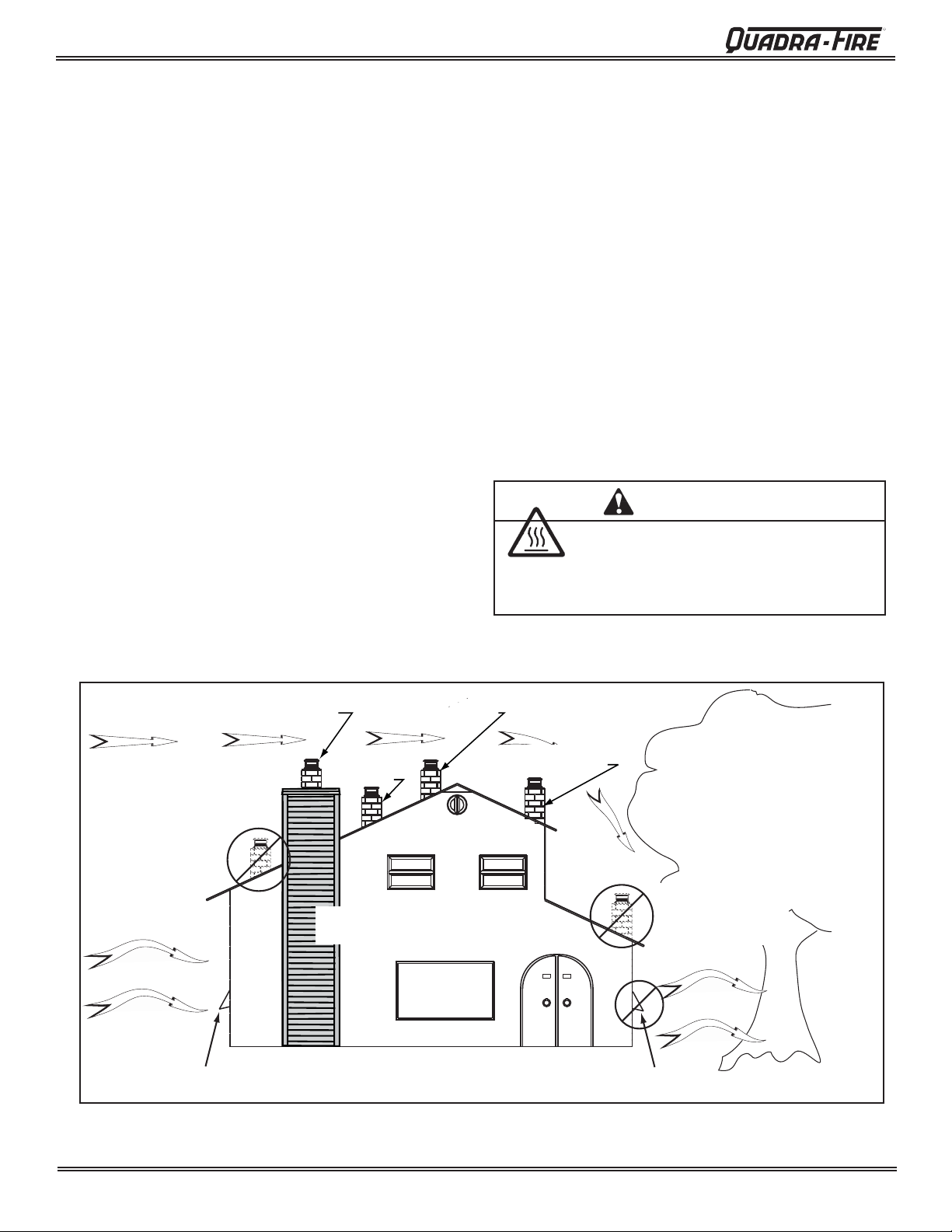
Location NOT recommended:
• Not the highest point of the roof
• Wind loading possible
Windward
Recommended:
Outside Air Intake
on windward side
Figure 6.1
Recommended Location:
• Above peak
Marginal Location:
• Below peak
Recommended:
• Insulated exterior chase
in cooler climates
Recommended Location:
• Above peak
• Inside heated space
Multi-level Roofs
Marginal Location:
• Wind loading possible
Location NOT recommended:
• Too close to tree
• Below adjacent structure
• Lower roof line
• Avoid outside wall
Leeward
NOT recommended:
Outside Air Intake
on leeward side
Page 6
7037-135G
August 31, 2010
R
4300 Wood Stove Series (ACC)
D. Flue Draft Considerations
Location of the appliance and chimney will affect performance. As shown in Figure 6.1 on page 6 the chimney
should:
• Be installed through the warm space enclosed by the
building envelope. This helps to produce more draft,
especially during lighting and die down of the fi re.
• Penetrate the highest part of the roof. This minimizes
the affects of wind turbulence and down drafts.
• Consider the appliance location in order to avoid
fl oor and ceiling attic joists and rafters.
Exterior conditions such as roof line, surrounding trees,
prevailing winds and nearby hills can influence stove
performance. Y our local dealer is the expert in your geographic
area and can usually make suggestions or discover solutions
that will easily correct your fl ue problem.
o be sure that your appliance burns properly, the chimney
T
draft (static pressure) should be approximately -.04 inch water
column (W.C.) during a low burn and -.10 inch W.C. during a
high burn, measured 6 inches (152mm) above the top of the
appliance after one hour of operation at each burn setting.
NOTE: These are guidelines only, and may vary somewhat
for individual installations.
E. Venting Systems
The venting system consists of a chimney connector (also
known as stove pipe) and a chimney. These get extremely
hot during use. T emperatures inside the chimney may exceed
2000F (1100C) in the event of a creosote fi re. To protect
against the possibility of a house fi re, the chimney connector
and chimney must be properly installed and maintained.
An approved thimble must be used when a connection is
made through a combustible wall to a chimney.
A chimney support package must be used when a connection
is made through the ceiling to a prefabricated chimney.
These accessories are absolutely necessary to provide
safe clearances to combustible wall and ceiling material.
Follow venting manufacturer’s clearances when installing
venting system.
F. Tools And Supplies Needed
Before beginning the installation be sure that the following
tools and building supplies are available.
Reciprocating saw
Pliers
Hammer
Phillips Head Screwdriver
Flat Blade Screwdriver
Plumb Line
Level
Tape Measure
Framing Material
Hi-Temp Caulking Material
Gloves
Framing Square
Electric Drill & Bits (1/4”)
Safety Glasses
1/2 in. - 3/4 in. length, #6 or
#8 self drilling screws (need 3
per pipe section connection)
G. Inspect Appliance & Components and
Pre-Use Check List
1. Place the appliance in a location near the fi nal
installation area and follow the procedures below:
2. Open the appliance and remove all the parts and
articles packed inside the Component Pack. Inspect
all the parts and glass for shipping damage. Contact
your dealer if any irregularities are noticed.
3. All safety warnings have been read and followed.
4. This Owner’s Manual has been read.
5. Floor protection requirements have been met.
6. Venting is properly installed.
7. The proper clearances from the appliance and chimney to combustible materials have been met.
8. The masonry chimney is inspected by a professional
and is clean, or the factory built metal chimney is
installed according to the manufacturer’s instructions and clearances.
9. The chimney meets the required minimum height.
10.
11. Plated surfaces have been wiped clean, if appli-
12. A power outlet is available nearby if installing
All labels have been removed from the glass door.
cable.
optional blower assembly.
Asphyxiation Risk.
• DO NOT CONNECT THIS UNIT TO A CHIM-
• DO NOT CONNECT TO ANY AIR DISTRIB-
May allow fl ue gases to enter the house.
August 31, 2010
WARNING
NEY FLUE SERVICING ANOTHER APPLIANCE.
UTON DUCT OR SYSTEM.
7037-135G
WARNING
Fire Risk.
Inspect appliance and components for damage.
Damaged parts may impair safe operation.
• Do NOT install damaged components.
• Do NOT install incomplete components.
• Do NOT install substitute components.
Report damaged parts to dealer.
Page 7
4300 Wood Stove Series (ACC)
R
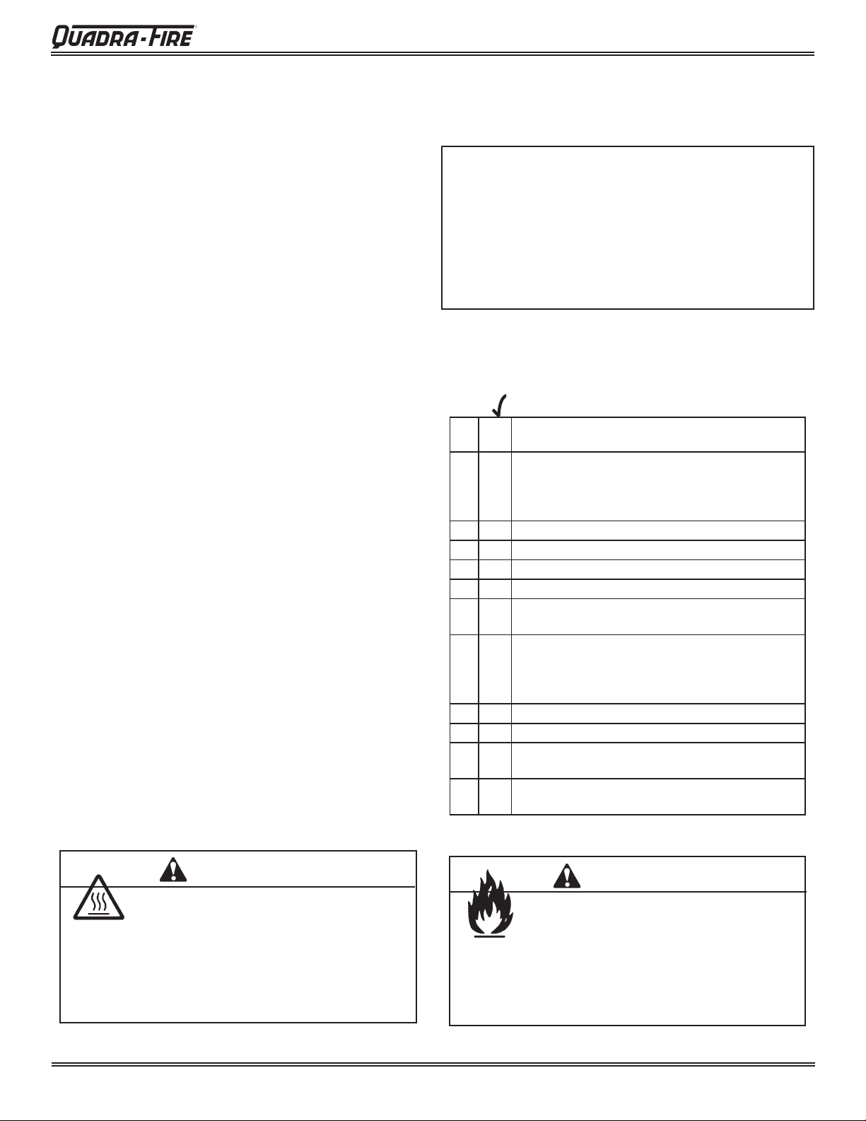
H. Typical Stove Systems
Stove system with masonry chimney
consists of:
• Stove
• Chimney Connector (stove pipe)
• Thimble
• Masonry Chimney
• Hearth Pad Floor Protection
Spark Arrestor Cap
1" (25mm) Clearance
With Firestop
Ceiling Joist
Combustible Wall
Thimble,
12" (305mm)
Of Brick
Floor
Protector
Concrete Cap
Fireclay Flue Liner
With Air Space
Rafter
Flashing
Eave
Sheathing
Outside Air Rear Vent
Outside Air
Termination Cap
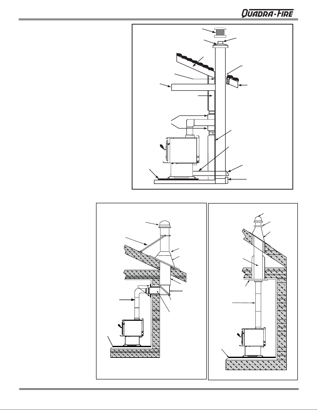
Stove system with prefabricated
metal chimney consists of:
• Stove
•
Chimney Connector
(stove pipe)
• Thimble (for exterior
chimney)
• Firestops
• Insulations Shields
• Storm Collar and Flashing
• Termination Cap
• Hearth Pad Floor Protection
Figure 8.1 Masonry Chimney
ListedTerminationCap
Roof Brace (if required)
Trim Collar on
Inside Wall
Chimney
Connector
Wall Support
Thimble
Storm Collar
Flashing
Listed Chimney
Insulated " T "
Airtight
Cleanout Door
Listed Termination Cap
Storm Collar
Flashing
Listed Chimney
Ceiling Support
Chimney
Connector
Page 8
Floor
Protector
7037-135G
Floor
Protector
Figure 8.3 Interior Prefabricated ChimneyFigure 8.2 Exterior Prefabricated Chimney
August 31, 2010
3
R
4300 Wood Stove Series (ACC)
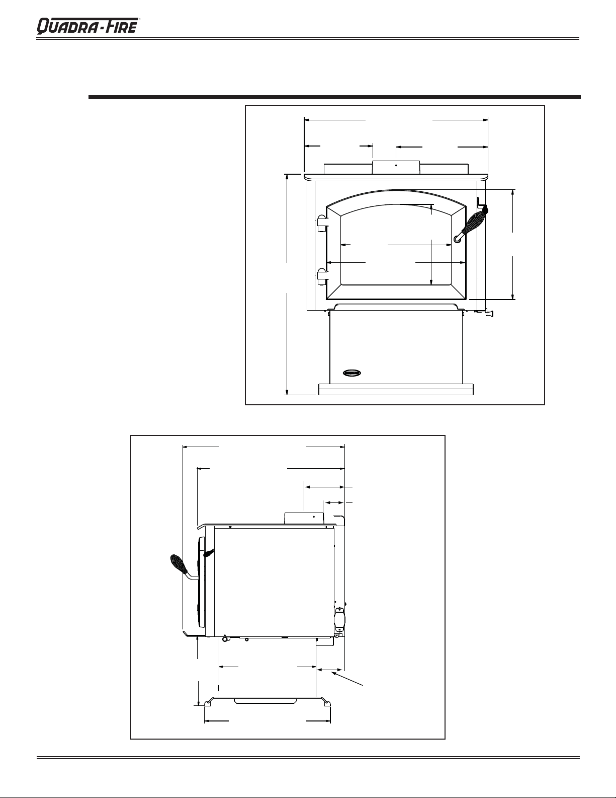
Dimensions and Clearances
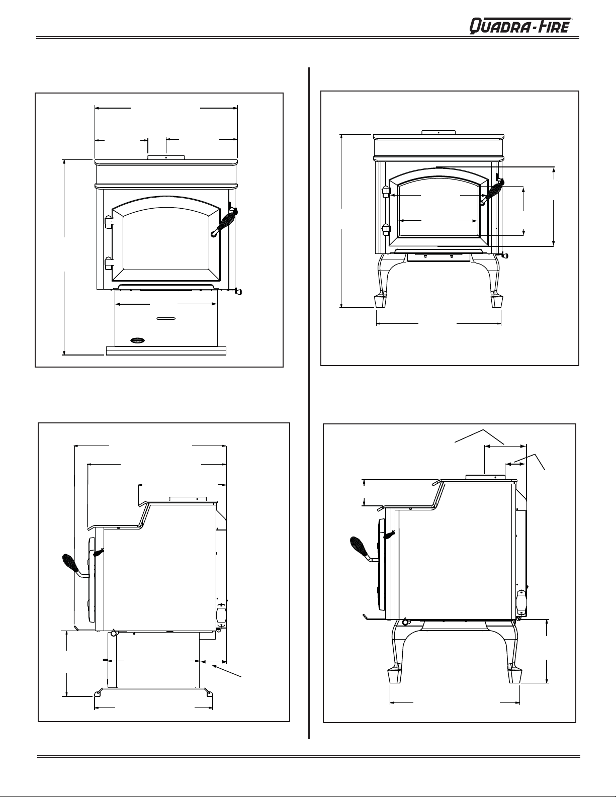
A. Appliance Dimensions
NOTE: Flue Collar size is 6 inch
(152mm) diameter (ID)
Millennium Model
31 in.
(762mm)
9-3/4 in.
(247mm)
26 in. (660mm)
15-1/16 in.
(383mm)
19-1/16 in.
(475mm)
C
L
13 in.
(330mm)
10-15/16 in.
(271mm)
14-15/16 in.
(373mm)
11-1/2 in.
(292mm)
Figure 9.1 Front View
28-11/16 in. (729mm)
26-5/16 in. (668mm)
16 in. (406mm)
6-11/16 in. (170mm)
3-7/16 (87mm)
C
L
4-1/2 in
C
L
(108mm)
Outside Air
Connection
August 31, 2010
Figure 9.2 Side View
20-3/4 in. (527mm)
7037-135G
Page 9
4300 Wood Stove Series (ACC)
Appliance Dimensions (Cont’d)
R
4300 Step Top Pedestal Model
26 in. (660mm)
C
9-3/4 in.
(248mm)
34-3/4 in.
(883mm)
L
18 in.
(457mm
)
13 in.
(330mm)
32-7/8 in.
(835mm)
4300 Step Top Leg Model
19-1/16 in.
(484mm)
15-1/16 in.
(383mm)
25-1/16 in.
(636mm)
14-15/16 in.
(379mm)
10-15/16 in.
(278mm)
Figure 10.1
11-1/2 in.
(292mm)
28-11/16 in.(729mm)
26-5/16 in. (668mm)
15-5/8 in. (397mm)
16 in. (406mm)
20-3/4 in. (527mm)
Figure 10.3
6-11/16 in.
(170mm)
3-1/2 in.
3-11/16 in. (94mm)
C
L
(89mm)
9-5/8 in.
C
L
4-1/2 in
(108mm)
Outside Air
Connection
(244mm)
23-1/8 in. (587mm)
Figure 10.2
Page 10
7037-135G
Figure 10.4
August 31, 2010
R
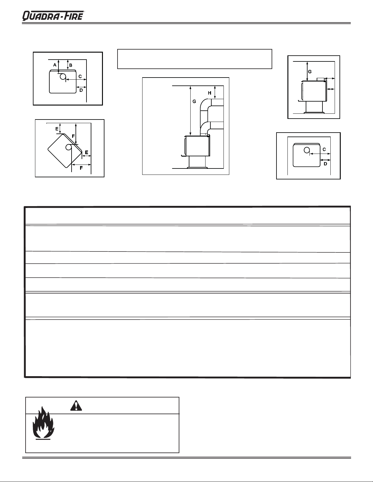
B. Clearances to Combustibles (UL and ULC)
4300 Wood Stove Series (ACC)
BACKWALL / SI DEWALL
NOTE: Clearances may only be reduced by means
ALCOVE SIDE VIEW
approved by the regulatory authority having jurisdiction
A
90° OFF TOP
UP & OUT CEILING
CLEARANCE
CORNER INSTALLATION
MINIMUM CLEARANCES TO COMBUSTIBLE MATERIALS In Inches & (Millimeters)
NOTE: All "A" , "C" and "F" Dimensions are to the inside diameter of the flue collar.
A B C D E F G H
INSTALLATION: Full Vertical OR Horizontal with Minimum 2 FT Vertical Off Stove Top
STOVETO CEILING
CLEARANCE
ALCOVE TOP VIEW
B
SINGLE WALL PIPE
Flat Top Model 15.5 (394) 11.75 (298) 24.5 (622) 14.5 (368) 10 (254) 17.5 (445) 53.5 (1359) 12 (305)
Step-Top Model 15.5 (394) 11.75 (298) 24.5 (622) 14.5 (368) 2 (51) 12 (305) 49.5 (1283) 12 (305)
DOUBLE WALL PIPE
Flat Top Model 9 (229) 5.25 (133) 24.5 (622) 14.5 (368) 10 (254) 17.5 (445) 53.5 (1359) 12 (305)
Step-Top Model 7.5 (191) 3.75 (95) 22 (559) 11.75 (298) 2 (51) 12 (305) 49.5 (1283) 5 (127)
INSTALLATION: 90° Elbow Off Top of Stove Through Backwall
DOUBLE WALL PIPE
Flat Top Model 8.5 (216) 6 (152) 24.5 (622) 15 (381) 10 (254) 17.5 (445) 53.5(1359) N/A
Step-Top Model 7.5 (191) 4 (102) 19 (229) 9 (229) 2 (51) 12 (305) 49.5 (1283) N/A
INSTALLATION: ALCOVE
factory-built Class "A" chimney, or a masonry chimney. (Mobile Home must be equipped with a spark arrestor). Maximum depth of Alcove
shall be no more than 48 inches (1220mm) with a minimum height of 49.5 inches (1283mm) to top of unit, and the referenced clearances.
*In Canada must comply with CAN/ULC-S269 M87 for the 650
DOUBLE WALL PIPE
Flat Top Model 13 (330) 10 (254) 24 (610) 14.5 (368) N/A N/A 53.5 (1359) 12 (305)
Step-Top Model 7.5 (191) 3.75 (95) 22 (584) 11.75 (298) N/A N/A 49.5 (1257) 5 (127)
Six inch (6") (152mm) diameter listed Double Wall air insulated connector pipe with UL103 HT* listed
o
C Factory-built chimney.
NOTE: Service Space
WARNING
Fire Risk.
• Comply with all minimum clearances to
combustibles as specifi ed.
• Failure to comply may cause house fi re.
In order to replace the tube channel assembly a clearance
of 19 inches (483mm) is required on the right side of stove
in order to remove the tubes with the stove in place.
If space is not available, the stove will have to be disconnected from the chimney to proceed with the tube replacement. See Figure 36 on page 36.
August 31, 2010
7037-135G
Page 11
4300 Wood Stove Series (ACC)
Installation
4
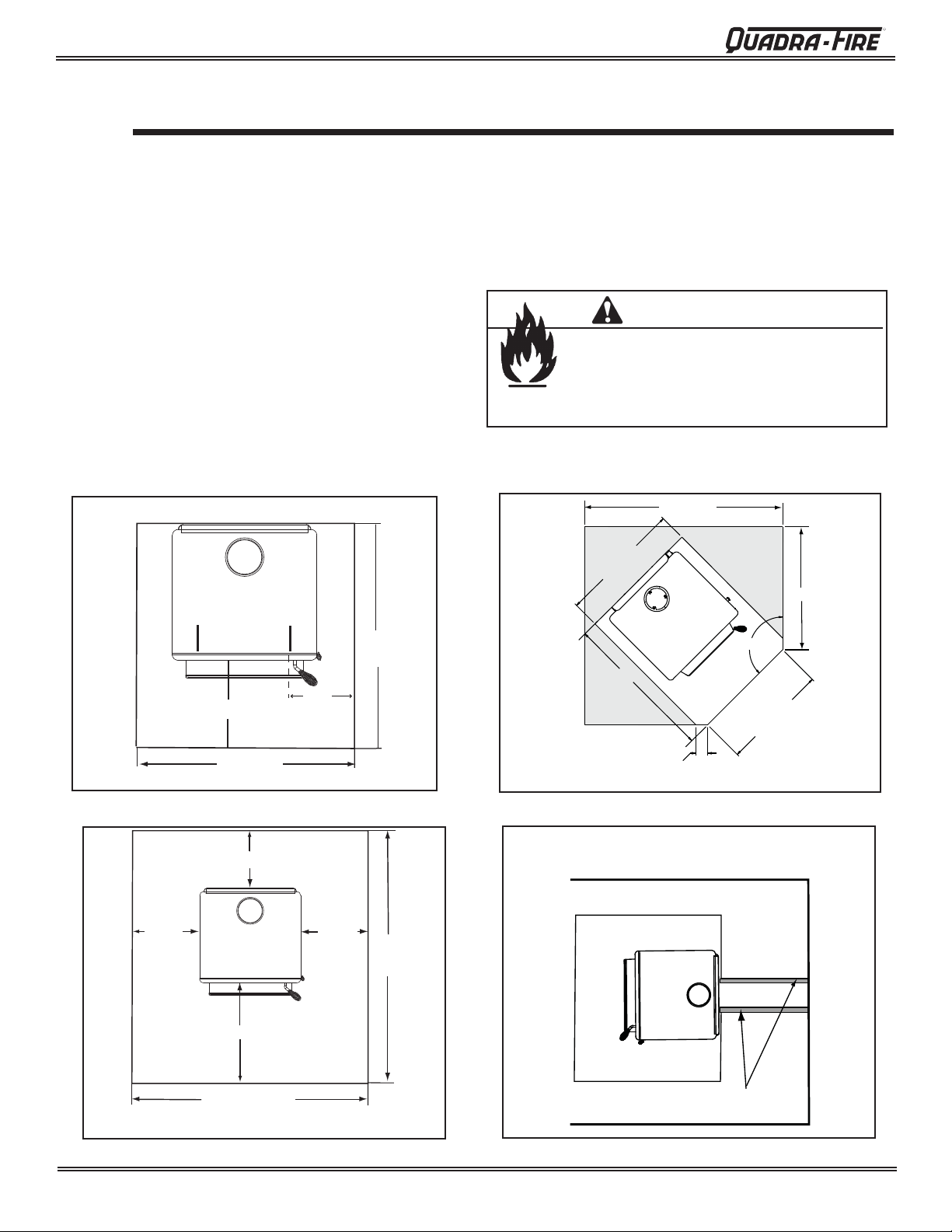
A. Hearth Protection Requirements
FLOOR PROTECTION: Floor protector must be non-com-
bustible material, extending beneath heater and to the front,
sides and rear as indicated. The fl oor must be non-com-
bustible or otherwise adequately protected from radiant heat
given off by the unit and from sparks and falling embers. A
layer of thin brick or ceramic tile over a combustible fl oor is
not suffi cient.
For US installations, i
of a minimum of 3/8 inch (9.5mm) thick metal clad millboard
or equivalent a minimum of 16
glass and 8 inches (203mm) to both sides of the fuel loading
door. Open the door and measure 8 inches (203mm) from
the side edge of the opening in the face of the appliance.
*See exception.
t is necessary to install a fl oor protector
inches (406mm) in front of
Millennium Model
R
In Canada, similar fl oor protection must be provided 18
inches (457mm) in front and 8 inches (203mm) from the
sides and rear of the stove. *See exception.
*EXCEPTION: Non-combustible fl oor protections must
extend beneath the fl ue pipe when installed with horizontal
venting and extend 2 inches (51mm) beyond each side.
See Figure 12.4.
WARNING
Fire Risk.
• Hearth pads must be installed exactly as
specified.
High temperatures or hot embers may ignite
concealed combustibles.
Figure 12.1
203mm
(8 in.)
Fuel loading door
16" from glass
31-5/8 in.
minimum
203mm (8 in.)
8 in.
203mm
(8 in.)
41-3/8 in.
minimum
USA
1334mm
(52-1/2 in.)
minimum
Figure 12.3
51-1/16 in.
31-5/8 in.
40-15/16 in.
3-1/16 in.
USA required
Canada recommended
optional
coverage
37 in.
135°
27-3/8 in.
USA
Figure 12.2
Page 12
457mm (18 in.)
1066mm (42 in.)
minimum
CANADA
7037-135G
Must extend 2 in. (51mm) beyond
each side of pipe (shaded area)
Figure 12.4
August 31, 2010
R
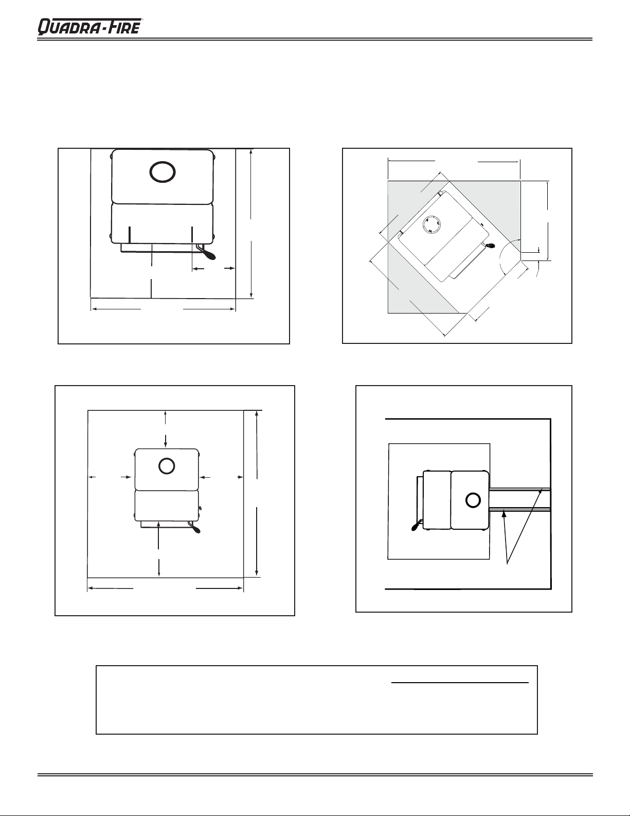
A. Hearth Protection Requirements (Cont’d)
Step-Top Uni-Body Model
4300 Wood Stove Series (ACC)
48-5/16 in.
Figure 13.1
203mm
(8 in.)
Fuel loading door
16 in. from glass
31-5/8 in.
minimum
203mm (8 in.)
8 in.
203mm
(8 in.)
41-3/8 in.
minimum
USA
1334mm
(52-1/2 in.)
minimum
Figure 13.3
31-5/8 in.
40-15/16 in.
USA required
Canada recommended
optional
coverage
135°
27-5/16 in.
29 in.
3 in.
USA
Figure 13.2
NOTE:
August 31, 2010
457mm (18 in.)
Must extend 2 in. (51mm) beyond
1066mm (42 in.)
minimum
each side of pipe (shaded area)
CANADA
Figure 13.4
• Illustrations and photos refl ect typical installations and are FOR DESIGN PURPOSES ONLY.
• Illustrations/diagrams are not drawn to scale.
• Actual installation may vary due to individual design preference
• Hearth & Home Technologies reserves the right to alter its products.
7037-135G
Page 13
4300 Wood Stove Series (ACC)
o
R
B. Outside Air Kit Installation
A source of air (oxygen) is necessary in order for combustion to take place. Whatever combustion air is consumed
by the fi re must be replaced. Air is replaced via air leak-
age around windows and under doors. In homes that have
tightly sealed doors and windows, an outside air source is
needed. An optional Outside Air Kit is avail
Included in OAK-ACC: Termination cap, (2) wire ties, flex
adapter, and fasteners
Included in SRV7033-041: Cover plate and sealing rope (see
Floor Installation Alternative below,
Figure 14.2)
Items Needed for Installation (not supplied)
• 4 inch fl ex aluminum pipe, or if using alternate material,
then it shall be made from durable, non-combustible,
heat resistant material up to 350
the required length for your installation.
• Phillips head screw driver
• Silicone sealant
• Drills and saws necessary for cutting holes through
the wall or fl ooring in your home.
able.
o
F. Cut the pipe to
WARNING
Fire Risk.
Asphyxiation Risk.
Do not draw outside combustion air from:
• Wall, fl oor or ceiling cavity
• Enclosed space such as an attic or garage
• Close proximity to exhaust vents or
chimneys
Fumes or odor may result
WARNING
Asphyxiation Risk.
Outside air inlet must be located to prevent blockage from:
• Leaves
• Snow or ice
• Other debris
Block may cause combustion air starvation
Smoke spillage may set off alarms or irritate sensitive individuals.
1. Remove all materials from packing box.
2. Using a #2 Phillips screw driver attach the fl ex adapter
to the stove using 4 screws. Figure 14.1.
3. For fl oor installations r
emove circular” knock-out” in the
base of the pedestal.
4. Floor & Rear Installation: Cut a 4 inch (102mm)
hole in outside wall or fl oor to accommodate outside
air piping. Use 4 inch (102mm) aluminum metal fl ex or
rigid piping to directly connect outside air to appliance
intake. Use the supplied termination cap with a rodent
screen. Seal between the wall (or fl oor) and the pipe
with silicone to prevent moisture penetration.
Flex Adapter
Wire Tie
For Floor Installations Remove
Circular “Knock-Out”
in Base of Pedestal.
Flex Line
Wire Tie
WARNING
Asphyxiation Risk.
Length of outside air supply duct shall NOT exceed
the length of the vertical height of the exhaust fl ue.
• Fire will not burn properly
• Smoke spillage occurs when door is opened due
to air starvation.
5.
Floor Installation Alternative: In some instances you may
not be able to install the fl ex pipe as show in Figure 14.1.
If that is the case, you will need to order SRV7033-041
which includes a cover plate and sealing rope as shown in
Figure 14.2. The goal is to seal the pedestal so no room
air can leak into the pedestal or cold air infi ltration.
Terminati
Cap
Rope to Seal
Pedestal
Cover
Plate
Figure 14.1 - Floor & Rear Installation
Page 14
7037-135G
Figure 14.2 - Floor Installation Alternative
August 31, 2010
Do not remove
.
R
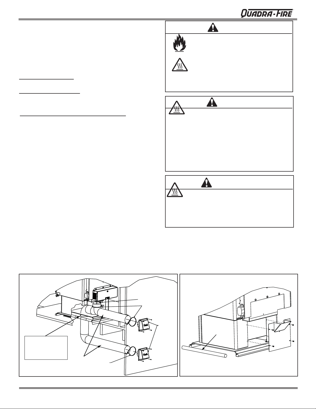
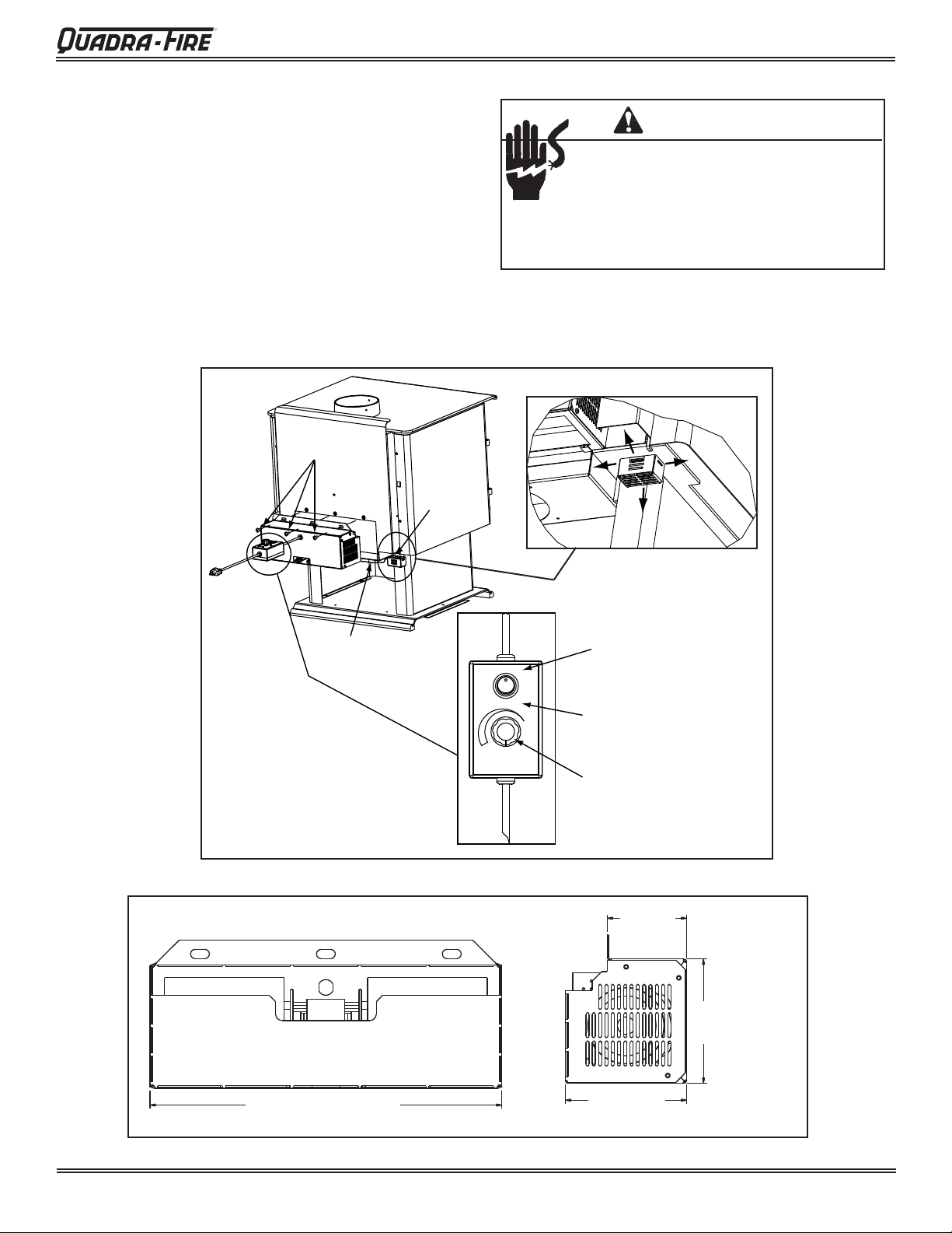
C. Blower (Optional)
1. Remove the 3 bolts (1/4”-20 Phillips head) on the outer
skin at the bottom rear of appliance.
2. Align holes in mounting fl ange of blower with bolt holes in
appliance. Blower should be positioned at bottom of rear
outer skin as shown in Figure 15.1.
3. Re-insert and tighten bolts, securing blower onto outer
wall of appliance.
4.
Place the bracket containing the snap disc and magnet
under the bottom left rear corner as shown in Figure 15.1.
See page 30 for detailed operating instructions for the
blower and snap disc.
Secure blower
with 3 bolts
Snap Disc
Bracket
with Magnet
4300 Wood Stove Series (ACC)
CAUTION
Shock Risk.
• Do NOT remove grounding prong from plug.
• Plug directly into properly grounded 3 prong
receptacle.
• Route cord away from appliance.
•
Do NOT route cord under or in front of appliance..
Figure 15.1
Secure wires
with wire tie
FAN
HIGH
MANUAL
AUTO
OFF
LOW
MANUAL: Over-rides the
Snap Disc
AUTO: Fan will turn ON/OFF
Automatically by the Snap Disc
Controls the Fan Speed
3-1/8 in.
(80mm)
4-15/16 in.
(125mm)
Figure 15.2
August 31, 2010
13-15/16 in. (355mm)
7037-135G
4-13/16 in.
(122mm)
Page 15
 Loading...