

Quadra-Fire 21M-ACC-NZ, 21M-ACC-AU, 43M-ACC-NZ Installations
QUADRA-FIRE 2100 & 4300 MILLENIUM ACC WOOD BURNER INSTALLATION INSTRUCTIONS
QUADRA-FIRE 2100 & 4300 MILLENIUM ACC WOOD BURNER INSTALLATION INSTRUCTIONS
Model:
21M-ACC-NZ
21M-ACC-AU
43M-ACC-NZ
INSTALLATIONS T O COMPLY WITH AS/NZS2918:2001
AND WILL REQUIRE A BUILDING CONSENT
IMPORTANT: Read all instructions carefully before starting installation. Failure to follow these
instructions may result in a fi re hazard and will void the warranty.
• Fig. 3,4,5 and Table 1 & 2 relate to installations with tested fl ue systems; as per AS/NZS 2918:2001 -
Appendix F, with a ceiling angle between 0° - 30° inclusive.
• For installations with a ceiling angle greater than 30°, refer to Fig. 6 & 7 and AS/NZS 2918:2001 4.6.3(b)
• Ceiling Plate may vary in size depending on ceiling angle. Please specify ceiling pitch prior to ordering the
ceiling plate.
• Quadra-Fire 2100 & 4300 Millenium ACC wood burner’s are tested and approved to the N.Z. National
Environmental Standards;
21M-ACC-NZ - 2100 Millenium ACC Softwood Certifi ed
Particulate Emissions = 0.6 g/kg Space Heating Effi ciency = 72%
21M-ACC-AU - 2100 Millenium ACC Hardwood Certifi ed
Particulate Emissions = 2.0 g/kg Space Heating Effi ciency = 81%
43M-ACC-NZ - 4300 Millenium ACC
Softwood Particulate Emissions = 0.4 g/kg Space Heating Effi ciency = 71%
Hardwood Particulate Emissions = 2.5g/kg Space Heating Effi ciency = 78%
www.quadrafi re.com
7037-141D
October 12. 2015
2100 & 4300 Millennium ACC Wood Burner
and Welcome to the Quadra-Fire Family!
Hearth & Home Technologies welcomes you to our tradition
of excellence! In choosing a Quadra-Fire appliance, you
have our assurance of commitment to quality , durability , and
performance.
This commitment begins with our research of the market,
including ‘Voice of the Customer’ contacts, ensuring we
make products that will satisfy your needs. Our Research
and Development facility then employs the world’s most
advanced technology to achieve the optimum operation of
4300 MILLENNIUM ACC
R
MILLENNIUM ACC WOODFIRE COMPLIANCE LABEL
This appliance has been TESTED TO AS/NZS4013 for Softwood by Applied Research Services Ltd. Report # 07/1717 Date tested: November 2007
This appliance has been TESTED TO AS/NZS4013 for Hardwood by HRL Technology Report # HCMG/12/016 Date tested: March 2012
OVERALL AVERAGE EFFICIENCY
AVERAGE PARTICULATE EMISSION FACTOR
MAXIMUM AVERAGE HEAT OUTPUT
SERIAL NO.
room for .14 x .875” S/N
007037
JAN FEB MAR APR MAY JUN JUL AUG SEP OCT NOV DEC
2015
2016 2017
1.5” x .375 Barcode Label
WETBACK - ALL MODELS
MODEL QUADRA-FIRE 4300 MILLENNIUM ACC
TESTED TO AS/NZS 4012
TESTED TO AS/NZS 4013
APPROVED FUEL
MANUFACTURED BY
our stoves, inserts and fi replaces. And yet we are old-fash-
ioned when it comes to craftsmanship. Each unit is meticulously fabricated and surfaces are hand-fi nished for lasting
beauty and enjoyment. Our pledge to quality is completed
as each model undergoes a quality control inspection.
We wish you and your family many years of enjoyment in
the warmth and comfort of your hearth appliance. Thank
you for choosing Quadra-Fire.
SOFTWOOD
71%
0.4 g/kg
10 kW
HARDWOOD
78%
2.5 g/kg
11.8 kW
BURN ONLY WOOD WITH A MOISTURE CONTENT LESS THEN 25% (dry
basis).
Wetbacks are NOT an approved option and must not be tted.
Hearth & Home Technologies, 1445 North Highway, Colville, WA
99114, United States of America.
PERFORMANCE MAY VARY FROM TEST VALUES DEPENDING ON ACTUAL
OPERATING CONDITIONS.
U.S. ENVIRONMENTAL PROTECTION AGENCY
Export stove. May not be operated within the United States.
INSTALLATION
DATE
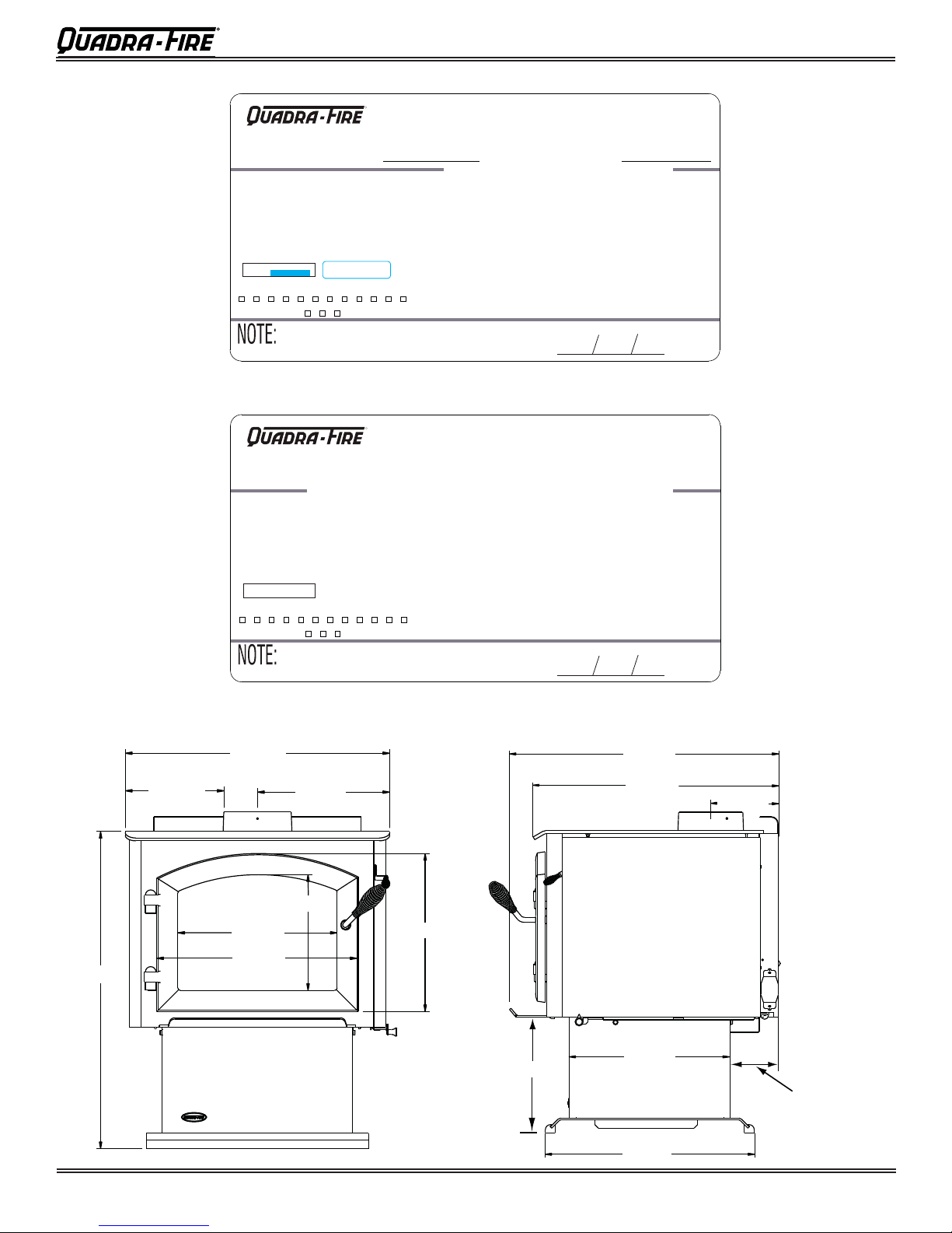
Fig. 2 - Quadra-Fire 4300 Millenium ACC Wood Burner Dimensions
660mm
C
247mm
762mm
L
383mm
475mm
330mm
271mm
373mm
292mm
729mm
668mm
406mm
7037-147B
170mm
C
L
C
L
108mm
Outside Air
Connection
Page 2
7037-141D
527mm
October 12, 2015
2100 & 4300 Millennium ACC Wood Burner
2100 (NZ-SOFTWOOD) MILLENNIUM ACC
R
MILLENNIUM ACC WOODFIRE COMPLIANCE LABEL
This appliance has been TESTED TO AS/NZS4013 by Applied Research Services Ltd. Report # 07/1716
ECan Authorisation Number
083786
ECan Expiry Date
Date tested: November 2007
24/10/2013
MODEL QUADRA-FIRE 2100 MILLENNIUM ACC
OVERALL AVERAGE EFFICIENCY BURNING SOFTWOOD
AVERAGE PARTICULATE EMISSION FACTOR BURNING SOFTWOOD
MAXIMUM AVERAGE HEAT OUTPUT BURNING SOFTWOOD
SERIAL NO. / NUMÉRO DE SÉRIE / SERIENUMMER
room for .14 x .875” S/N
007036
JAN FEB MAR APR MAY JUN JUL AUG SEP OCT NOV DEC
2012
PERFORMANCE MAY VARY FROM TEST VALUES DEPENDING ON ACTUAL
OPERATING CONDITIONS.
U.S. ENVIRONMENTAL PROTECTION AGENCY
Export stove. May not be operated within the United States.
WHEN TESTED IN ACCORDANCE WITH AS/NZS 4012
WHEN TESTED IN ACCORDANCE WITH AS/NZS 4013
1.5” x .375 Barcode Label
2013 2014
APPROVED FUEL
WETBACK - ALL MODELS
MANUFACTURED BY
72%
0.6 g/kg
9 kW
BURN ONLY SOFTWOOD WITH A MOISTURE CONTENT LESS THEN
25% (dry basis).
Wetbacks are NOT an approved option and must not be tted.
Hearth & Home Technologies, 1445 North Highway, Colville, WA
99114, United States of America.
INSTALLATION
DATE
7039-145C
2100 (AU-HARDWOOD) MILLENNIUM ACC
R
MILLENNIUM ACC WOODFIRE COMPLIANCE LABEL
This appliance has been TESTED TO AS/NZS4013 for Hardwood by HRL Technology Report # HCMG/12/014A Date tested: March 2012
MODEL QUADRA-FIRE 2100 MILLENNIUM ACC FREESTANDING WOOD STOVE
OVERALL AVERAGE EFFICIENCY BURNING HARDWOOD
AVERAGE PARTICULATE EMISSION FACTOR BURNING HARDWOOD
MAXIMUM AVERAGE HEAT OUTPUT BURNING HARDWOOD
SERIAL NO.
007044
JAN FEB MAR APR MAY JUN JUL AUG SEP OCT NOV DEC
2015
2016 2017
PERFORMANCE MAY VARY FROM TEST VALUES DEPENDING ON ACTUAL
OPERATING CONDITIONS.
U.S. ENVIRONMENTAL PROTECTION AGENCY
Export stove. May not be operated within the United States.
WHEN TESTED IN ACCORDANCE TO AS/NZS 4012
WHEN TESTED IN ACCORDANCE TO AS/NZS 4013
APPROVED FUEL
WETBACK - ALL MODELS
MANUFACTURED BY
81%
2.0 g/kg
7.2 kW
BURN ONLY HARDWOOD WITH A MOISTURE CONTENT LESS THEN
25% (dry basis).
Wetbacks are NOT an approved option and must not be tted.
Hearth & Home Technologies, 1445 North Highway, Colville, WA
99114, United States of America.
INSTALLATION
DATE
7039-148B
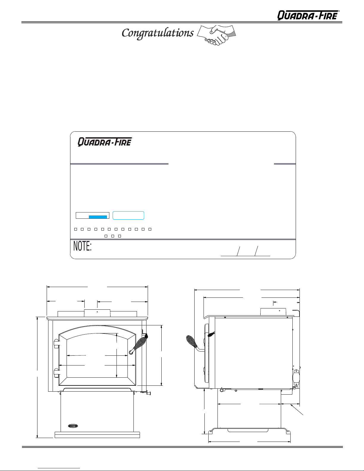
Fig. 1 - Quadra-Fire 2100 Millenium ACC Wood Burner Dimensions
709mm
219mm
594mm
C
L
342mm
432mm
297mm
235mm
324mm
292mm
671mm
618mm
406mm
527mm
C
L
170mm
C
L
108mm
Outside Air
Connection
October 12, 2015
7037-141D
Page 3
2100 & 4300 Millennium ACC Wood Burner
FLOOR PROTECTOR
1.QF.1B
Quadra-fire 2100 & 4300 Millennium ACC do not require a insulating Floor Protector, as they are tested
and comply with the minimum Floor Protector requirements of AS/NZS 2918:2001.
Note:
Fitted
200
ŀ The minimum Floor Protector sizes are specified in the clearance chart, see Table 1 & 2.
ŀ A Floor Protector can include ceramic tiles with grouted joints fixed directly onto a wooden floor or a
sheet of toughened glass, panel steel or any other non combustible material laid directly onto a
wooden floor.
ŀ If installed directly onto a concrete slab, the concrete slab can be considered as the floor protector,
but must maintain the minimum measurement listed.
PARALLEL POSITIONING
Fig. 3
A
E
B
D
Drawing not to scale
G
C
Table 1
A Min. Clearance from fi rebox to rear wall 150 160 200
B Min. clearance from fi rebox to side wall 550 280 400
C Min. distance from fi rebox opening to fl oor protector front 300 300 300
D Min. distance from fi rebox to fl oor protector side 76 76 69
E Min. distance from fl ue centre to side wall 847 577 730
F Min. distance from rear wall to front of fl oor protector 1034 1043 1 133
G Width of fl oor protector 746 746 798
Pioneer Double Flue Mounted Shield Universal
Pioneer Double Flue Mounted Shield Universal
A Min. clearance from firebox to rear wall 150
B
Min. clearance from firebox to side wall 550 400
C
Min. distance from firebox opening to floor protector front 300 300
D Min. distance from firebox to floor protector side 76 69
E Min. distance from flue centre to side wall 847 730
F Min dist ance from rear wall to front of floor protector 1034 1133
G Width of floor protector 746 798
DESCRIPTION
DESCRIPTION
Shall be Fitted
Shall be
Fitted
NOTE: HEAT SHIELD REQUIREMENTS FOR HEAT SENSITIVE WALLS
Clearances may be reduced by provision of an appropriately located heat shield refer to
AS/ NZS 2198:2001 3.2.3 Table 3.1
F
With Double Flue Shield Fitted
With Double Flue
Shield
2100-NZ 2100-AU 4300
2100 4300
Page 4
7037-141D
October 12, 2015
F
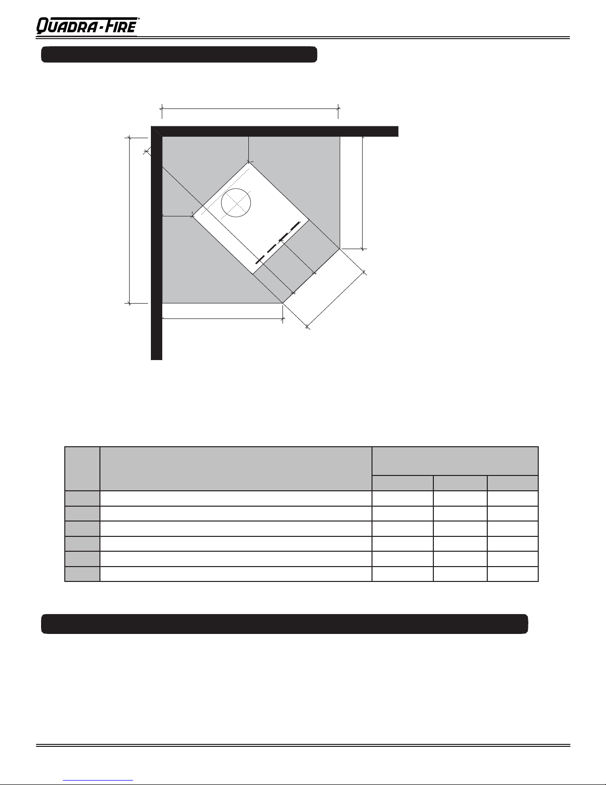
CORNER POSITIONING (45°)
CORNER POSITIONING
(45˚)
2100 & 4300 Millennium ACC Wood Burner
1.Q
.1C
Fig. 4
Drawing not to scale
C
A
C
A
D
B
E
F
Table 2
D
Pioneer Double Flue Mounted Shield Universal
A Min. clearance from fi rebox to corner walls 230 210 250
B Min. distance from fi rebox to fl oor protector front 300 300 300
C Min. distance from rear wall to fl oor protector front 1280 1228 1380
D Min. fl oor protector projection from wall 860 808 910
E Min. overall fl oor protector depth 1510 1440 1620
F Min. fl oor protector front width 594 594 660
Pioneer Double Flue Mounted Shield Universal
A Min. clearance from firebox to corner walls 230 250
B
Min. distance from firebox to floor protector front 300 300
C
Min. distance from rear wall to front of protector 1280 1380
D Min. floor protector projection from wall 860
E Min. overall floor protector depth 1510 1620
F Min floor protector front width 594 660
DESCRIPTION
DESCRIPTION
Shall be
Fitted
Shall be Fitted
FIREBOX INSTALLATION
1. If a separate floor protector is being used position now. Place the firebox on the floor protector to
suit the minimum installation clearances. (See Fig 3 or 4).
2. Seismically restrain the firebox and the floor protector to the floor.
3. Fit 2 x 6mm fixings suitable for the floor material. DO NOT over tighten.
4. Fit timber trim pedestal edging to front and back of base (optional).
With Double Flue
With Double Flue Shield Fitted
Shield
2100 4300
Fitted
2100-NZ 2100-AU 4300
910
October 12, 2015
7037-141D
Page 5

2100 & 4300 Millennium ACC Wood Burner
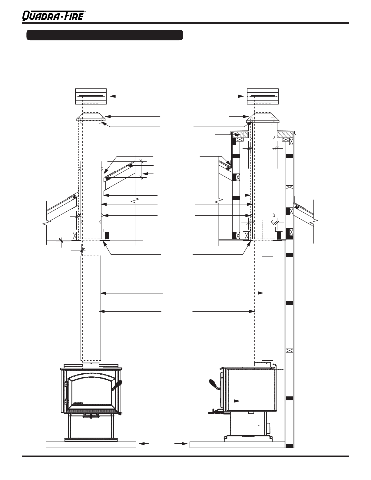
GENERAL INSTRUCTIONS FOR FLUE SYSTEM
ƒ Flue pipe installed crimp/narrow end down
ƒ Outer casings installed crimped/narrow end up. (Critical when exposed above the roof)
ƒ Inner casings - direction not critical
ƒ Flue pipes - seal all joints including firebox spigot.
- fix with a minimum of 3 stainless steel rivets
ƒ Flue pipe spacers - affix to flue pipe
ƒ Flue system termination point - Refer to AS/NZS 2918:2001 4.9.1, see Fig. 9.
ƒ Flue pipe shall extend not less than 4.6m above top of the floor protector as per
AS/NZS 2918:2001 4.9.1(a)
ƒ Façade or chase systems - same rule applies as above.
ƒ Roof penetration and flashing method refer to NZ Building Code E2.(From 01/07/05)
Note: These instructions apply to 150mm diameter flue pipe systems as tested to
AS/NZS 2918:2001
1. Either locate the appliance in position or by measuring at the ceiling mark the flue pipe centre
position. Check that the outer casing is unobstructed through the attic space or roof area.
2. Spike the centre with a nail. Transfer this position to the next surface above. Plumb bob/laser.
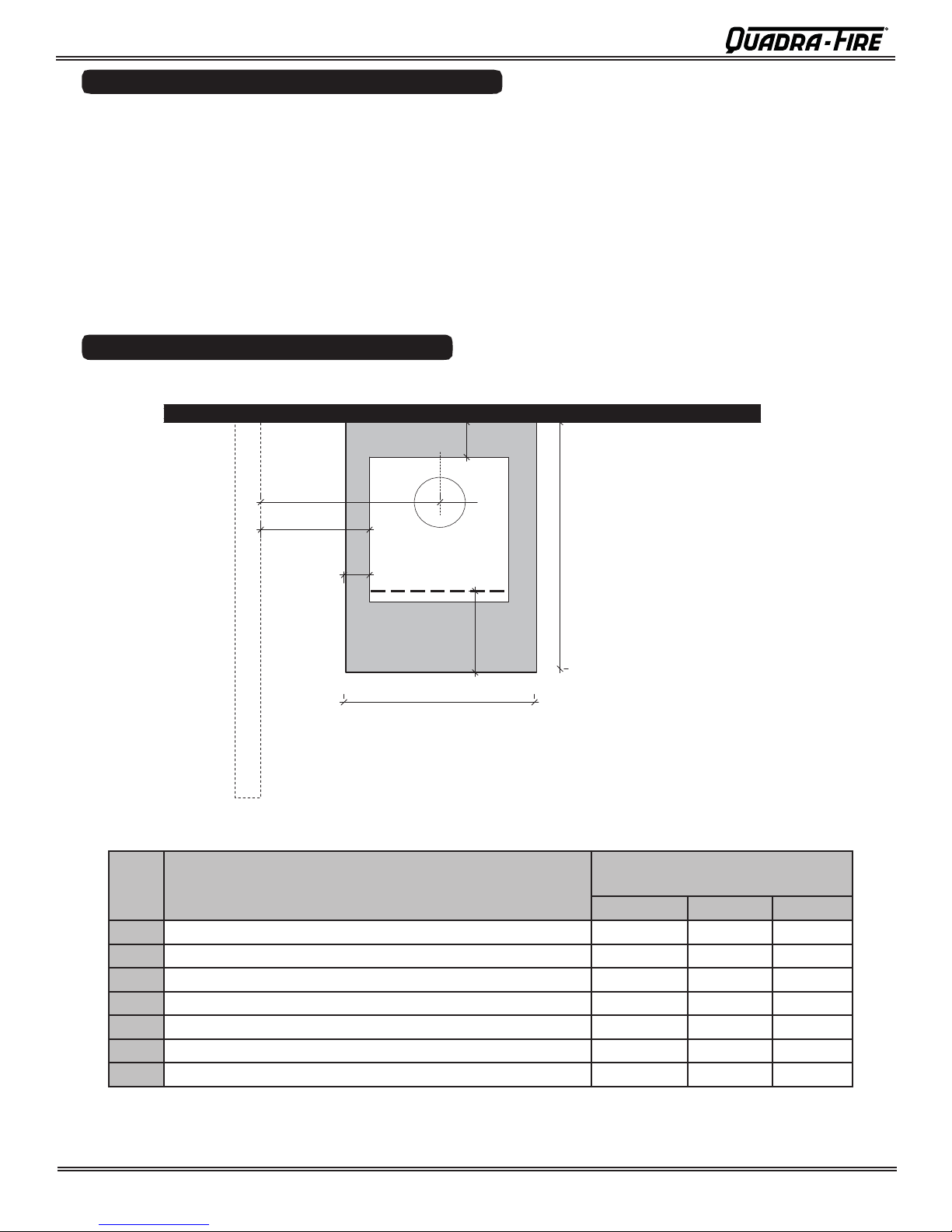
3. Cut out the ceiling penetration hole – square or rectangle – short axis equals outer casing
diameter plus 50mm, long axis as required. See Table 5 . Perform the same at the roof
penetration.
4. Frame out the hole with minimum 75 x 50 timber or as requ ired for roofing material. Minimum
requirement at roof penetration see NZ Building Code E2 Acceptable Soluti on (from 01/07/05).
5. Install the outer casing so that :-
(i) lower end is flush with the underside of the ceiling material and
(ii) with the addition of metal “L” brackets, affix to the outer casing at 90 degrees secure the outer
casing centrally to the ceiling and roof nogs. Alternatively substitute the “L” brackets for 25mm
thick non heat sensitive packers. Secure the outer casing th rough the packers with horizontal
fixings to the nogs. Refer to the General Instruction for termination height. The option of outer
casing slips to be taken into account.
6. Flash the outer casing to the roof material with the appropriate approved flashing.
7. If using an outer/inner casing combination, now install the inner casing ensuring it extends a
minimum 200mm above the high side of the roof penetration. If not using a combination see ‘11’
below.
8. Refer to Firebox Installation, points 1 & 2.
9. Prepare the ceiling plate and place upside down over the flue spigot.
10. Install the flue pipes by preferred method – either up or down the outer casing. Affix each length
per the notes in General Instructions (above). Extend the flue pipe above the outer
casing to suit the casing cover/cowl assembly.
11. If the inner casing has not been installed, install now. Refer to 7 above for minimum height.
12. Install the cowl assembly, i.e. Top spacer, casing cover and cowl.
13. Position and secure the ceiling plate with the screws and spacers.
14. Wipe the flue pipe to remove finger marks.
15. Refer to Firebox Installation, point 3.
16. If flue offset is required, refer to AS/NZS 2918:2001 4.1
1.QF.1D
Page 6
7037-141D
October 12, 2015
2100 & 4300 Millennium ACC Wood Burner
FLUE PENETRATION
FLUE PENETRATION
Tested flue systems, as per AS/NZS 2918:2001
Fig. 5
Drawing not to scale
25
12
12.5
ADD Cowl
Casing Cover
Spider Bracket
Approved Flashing
Roof Line
Inner Casing 200mm
above roof line
Outer Casing
Inner Casing
Internal Swage
Ceiling Plate
Double Flue
C
L
Quadra-fire Millennium
Floor
Protector
oversized casing cover
is necessary
Non combustible material
Hebel block or 12mm
Promina board or similar
under the flashing
V
ented
Pioneer
Shield
Flue Pipe
1.QF.1E
minimum 25mm gap
between flue pipe casing &
combustible material
25 25
25 25
C L
C
L
October 12, 2015
7037-141D
Page 7
2100 & 4300 Millennium ACC Wood Burner
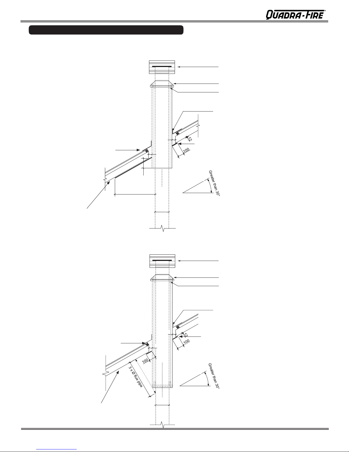
FLUE PENETRATION
Un-tested flue systems, as per AS/NZS 2918:2001, 4.6.3(b)
Fig. 6
AS/NZS2918:2001
Un-tested flue with sloped ceiling
penetration greater than 30° from
horizontal
A = 25mm
4.6.3(b)
Fig 4.6 = downward distance of
casing and 3 x ø flue distance of
the ceiling plate
Batten
150
A
A
Fig. 7
Ceiling
AS/NZS2918:2001
Un-tested flue with sloped ceiling
penetration greater than 30° from
horizontal
A = 25mm
4.6.3(b)
Fig 4.6 = 3 x ø flue from active flue
to heat sensitive surface
Batten
3 x Ø flue pipe
flue pipe
Ø
A
A
Ceiling
flue pipe
Ø
ADD Cowl
Casing Cover
Spider Bracket
Approved Flashing
Ceiling Plate
ADD Cowl
Casing Cover
Spider Bracket
Approved Flashing
Ceiling Plate
1.QF.1F
Page 8
7037-141D
October 12, 2015
 Loading...