

Page 1

High Definition Home and Business
Security Camera System
QT IP HD
Page 2

WelcomeTable of Contents
Getting Started
Warranty 3
Understanding Your System
What’s Included 4
Understanding Your NVR: Front Panel 5
Understanding Your NVR: Rear Panel 6
Setting Up Your System
Create Your Account 7
Connect Your Cameras 7–8
Connect NVR to Display 9
Connect Mouse 10
Connect to Router 10
Download Mobile App 11
Powering up the NVR 11
Startup Wizard 12-13
QT View Mobile App 14–15
QT View on a Computer 16
Installing Your Cameras
Getting the Most Out of Your Q-See Cameras 17-18
Resources / Appendix
Wizard Glossary 19
Understanding Your Control Bar 20
Video Search, Playback and Backup 21–24
Troubleshooting 25-27
Technical Support and Resources 28
2
Congratulations on your new surveillance purchase and
welcome to the Q-See community; where empowered
individuals demand the very best protection for their
homes and businesses. Your state-of-the-art Q-See
system produces sharp, clear images and is packed with
an abundance of features that make it easy for you to
keep a close eye on what matters most.
On behalf of our entire team, thank you for trusting
Q-See to be your choice for your personal
surveillance needs.
Sincerely,
Priti Sharma
President
Connect with us on social media.
Page 3

Warranty
To Activate Your 2-Year Limited Warranty
You Must Create An Account At: www.Q-See.com/welcome
We’re right here should you ever need assistance with your Q-See purchase.
Creating an account gives you access to:
1. The free QT View mobile app
2. Motion detection alerts
What does my warranty cover?
Q-See warrants that your product is free from defects
in materials and workmanship. With the exceptions
stated below, if your product is not operating properly,
Q-See will repair or replace your product according
to the guidelines stated in this warranty policy.
What doesn’t my warranty cover?
• Misuse, vandalism, or tampering
• Modification or alteration to hardware or software,
including the removal of Q-See logos or branding
• Cut or spliced cables or wires, or those coated
in insulation, caulk, or other materials
• Products that have been painted
3. Live customer support
4. The ability to upload and
save your proof of purchase
• Unsuitable physical or operating environment
beyond product specifications
• Improper maintenance or unauthorized repairs
• Incorrect power supplies being used with products
• Power fluctuations or surges - please
be sure to use a surge protector
• Failure caused by a non-Q-See product
being used with your Q-See products
• Loss of data - please be sure to regularly back up
any recorded data on a separate storage product,
like an external hard drive or computer
For expanded warranty details, visit www.Q-See.com/warranty
3
Page 4

Understanding Your System
What’s Included In Your Smart Surveillance Bundle
Cameras
Camera Cables
100’/30m
Ethernet Cables
One for each camera
NVR Cables NVR Power Supply
Your system will include one of
the options below
HDMI Cable
Colors on the back of the NVR are for reference only.
A
B
Network
Cable
This connects your
NVR to your router
4
C
Page 5
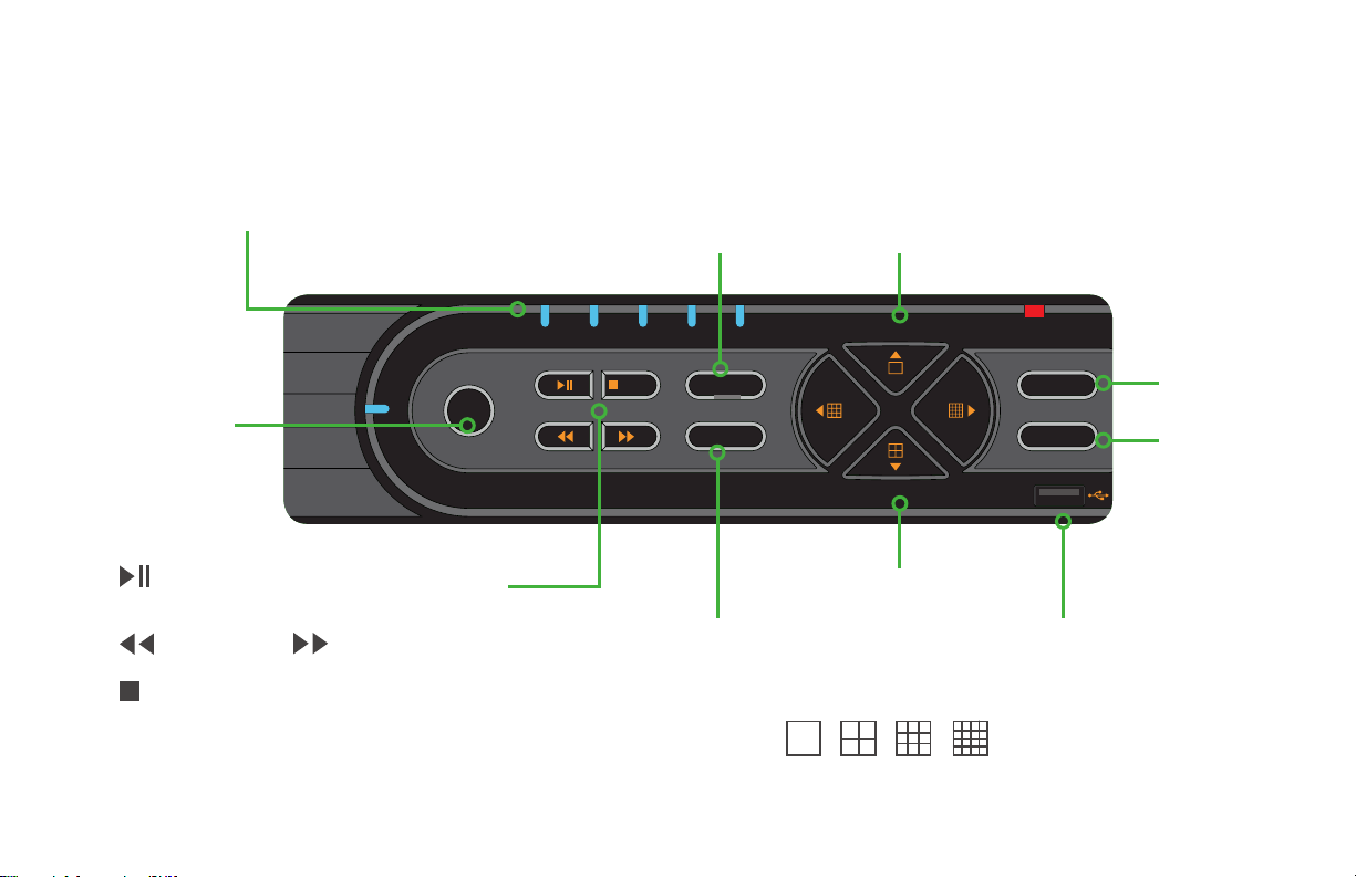
BACKUP PLAYNET
REC
HDD
REC
Menu/+
Backup/-
/ESC
Enter
Search
Understanding Your NVR: Front Panel
NOTE: Your NVR model may differ from that shown in this illustration.
LED Indicators: Show status
of power, HDD, record, etc.
REC:
Manually
begins
recording
: Launches PLAYBACK window.
Starts or pauses video
: Rewind
/ESC : Quit PLAYBACK mode. Exit
the current window or status. Switch
video output mode.
(Press and hold 10 seconds)
: Fast Forward
Menu/+ : Increase the
value in SETUP. Enter
menu in LIVE VIEW
Backup/- : Decrease
the value in SETUP.
Enter backup mode in
LIVE VIEW
Direction:
Navigate through
on-screen options
Multiscreen:
Change screen
display mode between
number of channels
1 4 9 16
Enter:
Confirm
selection
Search:
Enters
Search
Mode
USB Port: Connect USB
flash or external hard
drives to update firmware
or backup recordings
5
Page 6
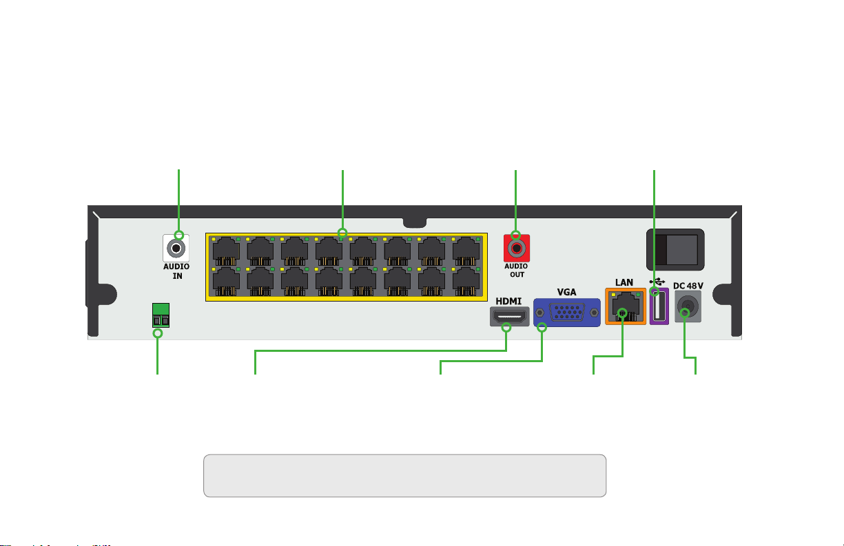
Understanding Your NVR: Rear Panel
NOTE: Your NVR model may differ from that shown in this illustration. Not all features may be present. Colors are for reference only.
Audio In: Single channel RCA
audio input from microphone
RS-485 (PTZ):
For Legacy Pan-Tilt
base control
6
POE Ports: Powers
High Definition cameras
and receives their video
HDMI: HDMI video output
Audio Output: RCA connection
for audio output – connect to an
amplified speaker
VGA: Video output for
connecting to monitor
LAN: Network
(Ethernet) port
19" or larger
ATTENTION: Some models may have two power supplies. Each will only fit
into its proper port. Do not force or modify plugs or ports.
USB: Connect
USB mouse
DC +48V:
Power input
Page 7

Setting Up Your System
Step 1: Create Your Account
Go to www.Q-See.com/welcome and follow the easy
steps to create your account.
ATTENTION: You must have an account to access:
Free mobile surveillance app, motion detection alerts, and
live customer support.
Step 2: Connect Your Cameras
A. Plug one end of the camera cable into the network
socket on the camera. Make sure that you hear a
“click” to ensure a good connection.
ATTENTION: The other camera lead is for use with a
power adapter (not included) when the camera is not
powered by the NVR and a POE (Power Over Ethernet)
switch is not available. Cover with electrical tape if not
used and exposed to weather.
7
Page 8

B. Plug the RJ45 connector on the other end of the
camera cable into an available Video-In POE port on
the back of the NVR. You will hear a click when the
cable is properly inserted.
These POE (Power Over Ethernet) ports will power
the camera and receive its video.
Repeat steps A-B for each camera.
Cameras will appear on screen in Live View in the
order they were connected
ATTENTION: Do not connect a
camera to the separate network (LAN)
port. This is used to connect the NVR
to your network and the Internet.
8
ATTENTION: Please test cameras and connections
prior to mounting. If there is no image or a dark screen
when you first connect the cameras, please see
Troubleshooting pg. 25.
Page 9

Step 3: Connect NVR to Display
Choose video display option A or B:
Option A: HDMI
A. Plug the included HDMI cable into the
NVR’s HDMI port.
B. Connect the other end of the HDMI cable
to the monitor or TV.
C. Plug the monitor or TV into a surge protector.
HD TV
Note: Colors are for reference only.
Option B: VGA Monitor
A. Plug a VGA cable (not included) into the
NVR’s VGA port.
B. Connect the other end of the VGA cable to the
monitor (19" or larger).
C. Plug the monitor into a surge protector.
Monitor
19”+
Note: Colors are for reference only. VGA cable not included.
9
Page 10

Step 4: Connect Mouse
Network
Router
Step 5: Connect To Router
Plug the mouse into the USB port on the back of the
NVR. If your model has two USB ports on the back,
either one will work.
A. Plug the included Network (Ethernet) cable into the
Network (LAN) port on the back of the NVR.
B. Connect the other end of the cable to an open
port on your router (not included).
You will hear a click when the cable is properly
connected
Network
Router
10
Page 11

Step 6: Download the
QTView Mobile App
Before starting the NVR, download our free
QT View mobile app to your mobile device.
ATTENTION: Do not log in. You will
create a password later.
Step 7: Powering up the NVR
A. Plug the NVR power supply cord into the
DC+48V Port on the back of the NVR.
B. Plug the power supply or power adapter
into a surge protector.
C. Turn on the NVR’s power switch (if present).
The NVR will beep as it powers up, and the
Start Up Wizard will appear on-screen after
a few minutes.
11
Page 12

Step 8: Startup Wizard
ATTENTION: In order to effectively
use the search function and maintain
accurate recordings, you must complete
the setup wizard.
Wizard
Language
English
Next
A. Set your desired language in the first window.
The NVR will restart and continue
in your chosen language.
12
Page 13

Next
Wizard
Language
English
Next
NextPreviousEdit Security Question Cancel
Wizard
Language
User name
Admin Password Setup
New Password
Confirm Password
admin
123456
123456
Display Password
English
Log in Automatically
IMPORTANT! Please change the Password. Keep it in a safe a
location. Select a security question, below, to recover a lost
password.
Wizard
Admin Password Setup
User name
New Password
Confirm Password
B. Create a new password for the
IMPORTANT! Please change the Password. Keep it in a safe a
location. Select a security question, below, to recover a lost
password.
Admin user account.*
Please write down your new password
in the space provided below.
admin
123456
123456
Display Password
*Password is case sensitive.
User Name:
admin
Password:
Default: 123456
Log in Automatically
NextPreviousEdit Security Question Cancel
Wizard
Date and Time
Time Zone
System Time
Date Format
Time Format
DST
NTP ON
GMT-12 West of the International
01/24/2016 04:18:42
Month/Day/Year
24-Hour
OFF
NextPrevious Cancel
C. Set the current date and time.
If you will be connecting the NVR to the Internet,
enabling Time Server allows the NVR to check a
network server to maintain accurate time. Setting the
start and end dates of Daylight Savings Time (DST) will
allow your NVR to automatically adjust its internal clock.
13
Page 14

NextPrevious Cancel
Time Zone
System Time
Date Format
Time Format
DST
GMT-12 West of the International
01/24/2016 04:18:42
Month/Day/Year
24-Hour
NTP ON
OFF
Date and Time
Wizard
Ethernet Port 1 (Online)
Network Settings
Obtain an IP address automatically
IP Address
Subnet Mask
Gateway
Open Wizard Next Time
192 . 101 . 819 . 962
255 . 255 . 255 . 0
192 . 101 . 99 . 1
Checking Network IP address…
Your DVR is connected to your network.
The local IP address for this DVR is: 192.101.8019.962
If you will be connecting to your DVR away from your local network (over the Internet), please click Next to continue with the
QT View setup.
If you will only be connecting to your DVR through your local network, use the local IP address to connect to your DVR on a
computer connected to the same network by entering it into the address bar in an Explorer/Edge (PC) or Safari (Mac) browser
window. You may also enter it into the QT View app on a mobile device. Using your WiFi network. This address will not work
when you are away from the building where your DVR is located. You may click Cancel now.
NextPrevious Cancel
Wizard
Next
NextPreviousEdit Security Question Cancel
NextPrevious Cancel
Wizard
Language
User name
Time Zone
System Time
Date Format
Time Format
DST
GMT-12 West of the International
01/24/2016 04:18:42
Month/Day/Year
24-Hour
NTP ON
OFF
Admin Password Setup
Date and Time
New Password
Confirm Password
admin
123456
123456
Display Password
English
Log in Automatically
IMPORTANT! Please change the Password. Keep it in a safe a
location. Select a security question, below, to recover a lost
password.
Network Settings
192 . 101 . 819 . 962
255 . 255 . 255 . 0
192 . 101 . 99 . 1
Ethernet Port 1 (Online)
Obtain an IP address automatically
IP Address
Subnet Mask
D. Click Next to allow your NVR to automatically
Gateway
Checking Network IP address…
Your DVR is connected to your network.
The local IP address for this DVR is: 192.101.8019.962
If you will be connecting to your DVR away from your local network (over the Internet), please click Next to continue with the
QT View setup.
If you will only be connecting to your DVR through your local network, use the local IP address to connect to your DVR on a
computer connected to the same network by entering it into the address bar in an Explorer/Edge (PC) or Safari (Mac) browser
window. You may also enter it into the QT View app on a mobile device. Using your WiFi network. This address will not work
when you are away from the building where your DVR is located. You may click Cancel now.
Open Wizard Next Time
connect to your network. If it is successful, it
will display a Success message along with your
LAN (Local Area Network) address. If the attempt
Wizard
is unsuccessful, you will receive a Failed message.
Ensure that your NVR is properly connected to
your network/router before clicking on Previous
to try again. Please refer to the Troubleshooting
section on page 21 if this problem persists.
NextPrevious Cancel
Step 9: QT View Mobile App
To view cameras on your mobile device, you will
need to add your NVR to the QT View.
A. Please choose how you would want to connect
remotely with your mobile device.
Wizard
QT View
Mobile App
Computer
iOS: Download QT View from App Store
Android: Download QT View from Google Store
1. Launch QT View App and click on the Bar Code at the bottom
2. Scan this QR code.
3. Enter the Username: admin
4. Enter your new Password (default is 123456)
The Account and Password show above are default.
IMPORTANT! Please keep your new password in a safe location.
The password can be recovered by answering the security question you’ve chosen on your DVR.
Open Wizard Next Time
ATTENTION: If your mobile device does
not have a camera, select the Computer
option and enter the number shown.
00867F1VE309
www.qseeqtview.com
NextPrevious Cancel
14
Page 15

B. Once you have launched the QT View Mobile App,
001122334455
My NVR
admin
Play
******
Add device
Tap on the QR Code Scan icon.
Add device
D. Once scanned, the App will return to the Login
Screen. The NVR’s ID will appear in the SN (serial
number) section. Enter the Account (User Name)
and your new password.
E. Tap Play to begin viewing your cameras
IP/DDNS or SN
Nickname
User
Password
Play
B
C. Scan the QR code displayed on the Wizard screen
with your mobile device.
ATTENTION: The QR Code
is also located on the top of
your NVR.
Q-See Scan N’View
12-34-AB-56-CD-F7
Add device
001122334455
My NVR
D
admin
******
E
Play
Always test your cameras to view live video before
you install them onto the wall.
Adding Mobile Devices
After completing the process on your first mobile device,
click the Previous button located on the Wizard window
and repeat Step 9 with that mobile device.
15
Page 16

QT View On Your Computer
After setup you can access your NVR over the
Internet on a computer or by downloading the QTView
application.
Go to www.QTView.com.
I. Click Add to access any NVRs.
If you changed your password, select the NVR, and
click Edit to enter the correct information.
J
K
G
Using the QTView app:
A. Click the link to download the Windows software.
B. Follow the on-screen instructions to install the program.
Accept license terms as requested.
C.
Launch the program by clicking on the icon on your desktop.
D.
Create a user name and
password for the program. These
do not need to be the same as
those on the NVR.
E. Log into QTView using the name and password you
created.
F. Select the computer hard drive you want to use to save
video.
G. In the Control Panel, click Add Device.
H. QTView will automatically scan your network for any
NVRs connected to it.
16
J. Click the Live Preview tab
K. Click and drag Root into a blank square. The cameras
will load automatically.
Using a Browser:
PC: Use Internet Explorer, Firefox or Chrome with IE plug-in
Macintosh: Use Safari or Firefox
A. Enter your NVR’s serial number on the label on the
NVR’s case.
B. Enter the User Name and Password you created in the
Software Menu.
C. Select language.
D. Click on Login to begin viewing your cameras.
ATTENTION: Search “QTView” at
www.Q-See.com/support for more info.
Page 17

Get the Most Out of Your Q-See Cameras
Follow these tips to maximize the life and performance of your cameras.
Distance from viewing/recording device
Mounting surface thickness
Mount your camera in a wall that is at least 2.5" thick.
Avoid direct exposure to weather
Mount your camera under an eave or awning if possible.
17
Page 18

Do not place camera behind a window
Do not place near high voltage wires or
other sources of electrical interference
Light levels should be approximately the
same between camera and target area
Legal Considerations
Always check state and local laws before installing cameras.
(2011 NEC 820.44)
18
Page 19

Resources / Appendix
Wizard Glossary
DST (Daylight Savings Time): Set DST to change where applicable. Click
“Set” to enter the start and end dates. Make sure the box is checked.
NTP (Network Time Protocol): This maintains the accuracy
of the NVR’s clock. Check the box to turn on.
Language: This is the language the NVR will use.
NOTE: If a new language is selected, the NVR will restart. The wizard will
continue in English but menus will be in the selected language.
Local IP Address (LAN): The NVR’s address on your local network.
IP: Internet Protocol. IP devices communicate with each
other via a local network or over the Internet.
POE: Power Over Ethernet. Uses a standard Ethernet cable to transmit power
and commands to the camera while receiving video back from it.
NVR: Network Video Recorder. Work with IP cameras connected to it directly or over a network.
19
Page 20

Understanding Your Control Bar
Control Bar
The NVR’s on-screen menus are accessed
through the Control Bar which appears when the
mouse is moved to the bottom of the screen.
There is a combination of quick-access icons as
well as a pull-up menu of options on the left.
Admin
Search and Save
Setting
Logout
Shutdown
Screen Display
Mode
20
Account: Shows which user is logged in.
Search and Save: Search for recorded video, play
it back and save it to an external USB drive.
Settings: Opens the Settings Menus to adjust your system.
Screen Display Mode: Choose the which live
video channels will be displayed on screen.
Sequence: Cycle through a selection of live video channels.
Account
Search and Save
Quick Playback: Quickly play back video. Choose from
the past five seconds through the past five minutes.
Manual Record: Overrides current settings to
record video on all channels until deselected.
Settings
Info: Displays a summary of your NVR and its status.
OSD
OFF
Sequence Manual
Quick
Playback
Info
Record
Page 21

Video Search, Playback and Backup
Your NVR records video
captured by your cameras to
its internal hard drive. These
records can be accessed
by selecting Search and
Save in the pull-up menu.
You can search for video
that was recorded during
a certain time, by type of
recording, and by reviewing
snapshots of recordings.
Admin
Search and Save
Setting
Logout
Shutdown
Once you’ve found the desired video, you can play it back
and then save your files to a removable USB flash drive
in a format that is easily playable on your computer.
Setting Search Time
You will need to set the start and end times for your
video searches using the pull-down calendars in the
upper right. Click on to open the calendar.
Click on a field (month, day, hour, etc.) and use the scroll
wheel on the mouse to select the desired date and time.
Search by Time: This is the best way to search
one or more cameras to identify an incident.
Search by Event: This allows you to search
through incidents which the system has
flagged, one camera at a time.
Search by Snapshot: This searches the snapshots
(still images) triggered by an incident. These can be
used to narrow down a video record search, or they
can be exported for use outside of your system.
Click OK to close the window.
01/24/2016 04:18:42
D
2014
2015
2016
2017
2018
12
11
22
23
M
24
1
2
25
3
26
2
16
3
17
Y
Hr
4
18
5
19
6
20
CancelOK
Min
40
41
42
43
44
Sec
21
Page 22

Playback Close
Manual Schedule Sensor Motion
20:00 22:00 24:00
24
Searching by Time
A. Set the start and end times of your
search.
B. Select which camera(s) to search.
A
Search and Save
By Time By Event Snapshots
01/24/2016 04:18:42
01/24/2016 04:38:42
Camera001 Camera002
C. Click Search
D. Video recorded during the search
period will appear as color-coded bars,
showing the time and duration.
Playback (Single Camera)
E. Click on the timeline where you want
playback to start. The blue time marker
will snap to that position.
F. Select a channel in the pull-down and
Press
ATTENTION: Pressing Playback (G)
will open full screen mode showing
video from multiple cameras.
Functions operate as described
above. Press to back up files.
22
B
Camera003 Camera004
Camera005 Camera006
Camera007 Camera008
Search
Camera002
00:00 02:00 04:00 06:00 08:00 10:00 12:00 14:00 16:00 18:00 20:00 22:00 24:00
01-24-2016 02:28:34
01-24-2016
Backup Playback Close
E GC D
F
Manual Schedule Sensor Motion
24
Backup
H. Click and drag on the timeline to
select the video(s) to back up.
I. Press Backup
Insert a USB flash drive into the
10:00 12:00 14:00 16:00 18:00
01-24-2016
Backup
port on the front of the NVR and
follow the on-screen instructions.
H
I
Page 23

By Time By Event Snapshots
Backup Playback Close
12:00
Type Time Period Duration
Manual 5 Mins
Manual
Manual
Manual
SensorSchedule Motion
Playback Close
12:00
Searching by Event
A. Set the start and end times of your
search.
B. Select which camera(s) to search.
A
Search and Save
By Time By Event Snapshots
01/24/2016 04:18:42
01/24/2016 04:38:42
Camera001 Camera002
C. Click Search
D. Video recorded during the search
period will appear in a list.
E. Refine your search by selecting the
typer of event.
Playback
F. Select a file to view and press Playback
ATTENTION: Video events
will play back one at a
time. Pressing Playback will
change to full-screen mode.
B
Camera003 Camera004
Camera005 Camera006
Camera007 Camera008
Search
Backup
G. Select the file(s) you want to
backup
H. Press Backup
Insert a USB flash drive into the
port on the front of the NVR and
follow the on-screen instructions.
Camera Name Type Time Period Duration
Camera 01
Camera 02
Camera 03
Camera 04
Manual
Manual 5 Mins
Manual
Manual
Manual
SensorSchedule Motion
Backup Playback Close
EC D
Camera Name
Camera 01
Camera 02
Camera 03
Camera 04
Manual
F
Backup
G
12:00
H
23
Page 24

Searching by Snapshot
A. Set the start and end times of your
search.
B. Select which camera(s) to search.
C. Click Search
D. Snapshots of video recorded during
the search period will appear in
order of the time they were created
- regardless of channel - below the
playback window.
Playback
E. Select a snapshot to view and press
to begin a slide show of the
snapshots.
24
A
B
Search and Save
01/24/2016 04:18:42
01/24/2016 04:38:42
Camera002 Camera002
Camera002 Camera002
Camera002 Camera002
Camera002 Camera002
Search
Backup
F. Select a snapshot to save
(export) to a USB drive and
click
Insert a USB flash drive into
the port on the front of the
NVR and follow the on-screen
instructions.
By Time By Event Snapshots
Close
EC D
F
Page 25

Troubleshooting
Testing for power and night vision
After you connect your camera to the NVR and power, if you do not see a video image on screen and your
NVR does not display a “video loss” message you should test your camera to ensure it is properly connected.
1. With your camera(s) still connected to power,
cover the lens end of your camera with your
hand or an object to completely block it.
2. Keep the lens blocked for 10 seconds. You should see
a faint red glow from the infrared LEDs. This indicates
that your camera has power and is working properly.
If you still do not have a video signal from the camera, check that the video cable is
properly connected to both the camera and the NVR as shown in Step 2 on pages 7 and 8.
Other tests:
• Connect the camera to a cable that has a working camera attached. If the camera works,
the cable will need to be replaced through the RMA process at www.Q-See.com/support.
• Connect the cable to a different channel on the NVR. If you see video, then the culprit is a bad channel input and the
NVR will need to be replaced through RMA.
25
Page 26

Troubleshooting
Cable extended to more than 200 feet. The camera
power supply/power splitter combination is only
designed to power cameras up to 200 feet. Any cameras
beyond that distance will need their own power supply
which is available at www.q-see.com.
Dark video image. Some cameras feature an infrared
cut filter to improve daytime video images. This can
sometimes become stuck. Place a hand over the lens for
10 seconds to trigger night vision mode. You may hear a
soft click as the filter resets.
Upside down video image. Change the position of
your camera to correct. Or, click on the live video from
that camera. A tool bar will appear above the video
image. Click on the icon to open the Image Adjust
window. Select the Flip option at the bottom.
Camera looking through window has video image
during day, but not at night. The LEDs on the camera
act as a flashlight and, at night, this light is being
reflected by the window back at the camera. You will
need to reposition the camera outside the window.
Camera video is very dark during one time of day,
but lighter during others. Reposition the camera. Any
sun or artificial light shining directly onto the lens will
backlight the subjects in the camera’s field of view and
cause them to appear dark and/or washed out. Keep in
mind that the sun changes positions over the course of a
year as well as during the day.
Camera on a metal building has excessive static.
The camera will need to be separated from the metal
building by using a rubber gasket.
26
Page 27

Troubleshooting
Network Troubleshooting.
Check that the network cable is properly connected to
the LAN port on the back of your NVR and to a network
port on your router. The lights on both ports should blink
occasionally to indicate that data is being transmitted.
If the cable is properly connected, but no data is
transmitting, replace the cable or try another port on the
router.
Your NVR must be connected directly to the router and
not through a network hub or switch.
Your router must have DHCP enabled. Consult your
router’s manual to determine if it has this feature and
how to enable it. If your router does not feature DHCP,
you may use one of the connection methods described
in the accompanying Network Setup Poster.
27
Page 28

24/7 Online Support Portal and Knowledge Base
www.q-see.com/support
28
Repairs and Returns
Support Videos
Software
Live Phone Support
Mon-Fri : 6AM–7:00PM PST
1-877-998-3440
Additional Support
Chat Support
Mon-Fri: 6AM–7PM PST
Sat-Sun 9AM–5PM PST
How–To’s
Firmware Updates
Manuals and Guides
Languages
English, Spanish
 Loading...