

Page 1

H.264 Dual Stream Network DVR
8 Channel CIF@240fps & D1@240fps Digital Video Recorder
USER MANUAL
Model #:
QT528
www.q-see.com
Rev 12/6/2010
Page 2

CAUTION
Please read this user manual carefully to ensure that you can use the device correctly and
safely
The contents of this manual are subject to change without notice
This de vice should be used with the power supply provided. If the DVR is not going to be
used for an extended period of time unplug it.
Do not install this device near any heat sources such as radiators, heat registers, stoves or
other device that produce heat.
Do not install this device where it is exposed to water. Clean only with a dry cloth
Do not block any ventilation openings; make sure there is good ventilation around the DVR.
Do not power off the DVR while it is recording! The correct procedure is to stop recording
first by selecting the “shut-down” button at the right of the menu bar to exit, and finally to cut
off the power.
This machine is designed for indoor use. Do not expose the machine to rain or a moist
environment. If any objects or liquids get into the machine’s case, please cut off the power
supply immediately, and have qualified technicians check the machine before restarting.
Refer all servicing to qualified service personnel other then replacing hard drives or
batteries.
1
Page 3

Table of Contents
1. INTRODUCTION .................................................................................................................................................. 4
1.1 DVR Introduction ................................................................................................................................................................................................................ 4
1.2 Main Features .................................................................................................................................................................................................................... 4
2. GETTING STARTED ............................................................................................................................................ 6
2.1 Connecting to a monitor or TV ............................................................................................................................................................................................ 6
2.2 Insta lling Hard D rive ........................................................................................................................................................................................................... 7
2.2.1 Install DVD Writer .................................................................................................................................................................................... 7
2.3 Front Panel De s criptio ns .................................................................................................................................................................................... 8
2.4 Rear Panel Layout ............................................................................................................................................................................................. 9
2.5 R emote Control ................................................................................................................................................................................................. 9
2 6 Control with Mouse .......................................................................................................................................................................................................... 10
2.6.1 Connect Mouse ...................................................................................................................................................................................................... 10
2.6.2 Use Mouse ............................................................................................................................................................................................................. 11
3. BASIC FUNCTION ............................................................................................................................................. 12
3.1 Power On/Off ................................................................................................................................................................................................................... 12
3.1.1 Power On ............................................................................................................................................................................................................... 12
3.1.2 Power Off ............................................................................................................................................................................................................... 12
3.2 Login ................................................................................................................................................................................................................................ 13
3.3 Live P review .................................................................................................................................................................................................................... 13
3.3.1 Live Playbac k ......................................................................................................................................................................................................... 14
4. MAIN MENU SETUP GUIDE ............................................................................................................................. 15
4.1 Basic Configuration .......................................................................................................................................................................................................... 16
4.1.1 Setup ..................................................................................................................................................................................................................... 16
4.1.2 Time & Date ........................................................................................................................................................................................................... 17
4.1.3 DST ....................................................................................................................................................................................................................... 17
4.2 Live Configuration ............................................................................................................................................................................................................ 18
4.2.1 Live ........................................................................................................................................................................................................................ 18
4.2.2 Host Monitor ........................................................................................................................................................................................................... 19
4.2.3 SPO T ..................................................................................................................................................................................................................... 19
4.2.4 Mask ...................................................................................................................................................................................................................... 20
4.3 Record Config uration ....................................................................................................................................................................................................... 21
4.3.1 En able ................................................................................................................................................................................................................... 21
4.3.2 Record stream........................................................................................................................................................................................................ 22
4.3.3 Time ....................................................................................................................................................................................................................... 23
4.3.4 Recycle Record ...................................................................................................................................................................................................... 23
4.3.5 Stamp .................................................................................................................................................................................................................... 24
4.4 Sched ule Configuration .................................................................................................................................................................................................... 24
4.4.1 Schedule ................................................................................................................................................................................................................ 25
4.4.2 Motion .................................................................................................................................................................................................................... 25
4.4.3 Se nsor ................................................................................................................................................................................................................... 26
4.5 Alarm Configuration .......................................................................................................................................................................................................... 26
4.5.1 Se nsor (to setup optional external motion sensors) ................................................................................................................................................. 27
4.5.2 Motion .................................................................................................................................................................................................................... 28
4.5.3 Vide o Loss ............................................................................................................................................................................................................. 30
4.5.4 Other Alarm ............................................................................................................................................................................................................ 31
4.5.5 Alarm Out ............................................................................................................................................................................................................... 31
4.6 Network Configuration ...................................................................................................................................................................................................... 32
4.6.1 Network.................................................................................................................................................................................................................. 33
4.6.2 Su b Stream ............................................................................................................................................................................................................ 34
4.6.3 Email ..................................................................................................................................................................................................... 34
4.6.4Other settings .......................................................................................................................................................................................................... 35
4.7 User Management Configuration ...................................................................................................................................................................................... 36
4.8 P. T.Z configuration ............................................................................................................................................................................................................ 37
2
Page 4

4.9 Advanced ........................................................................................................................................................................................................ 41
4.9.1 Reset ..................................................................................................................................................................................................................... 42
4.9.2 Import/Export ......................................................................................................................................................................................... 42
4.9.3 Block/Allow list ....................................................................................................................................................................................... 42
5. RECORD, SEARCH, PLAYBACK AND BA CKUP ........................................................................................... 43
5.1 Time Search ..................................................................................................................................................................................................................... 43
5.2 Event Search ................................................................................................................................................................................................................... 44
5.3 File Manager .................................................................................................................................................................................................................... 44
6. DVR MANAGEMENT ......................................................................................................................................... 46
6.1 Checking System Information ........................................................................................................................................................................................... 46
6.1.1 System Information ................................................................................................................................................................................ 46
6.1.2 Event Information ................................................................................................................................................................................... 46
6.1.1 Log Informati on ...................................................................................................................................................................................... 47
6.1.2 Network information ............................................................................................................................................................................... 47
6.1.1 Online Information .................................................................................................................................................................................. 47
6.1.2 Manual Alarm ......................................................................................................................................................................................... 48
6.1.3 Disk Manager......................................................................................................................................................................................... 48
6.1.3 Upgrade ................................................................................................................................................................................................. 48
6.1.4 Logoff .................................................................................................................................................................................................... 48
7. REMOTE SUR VEI L LA N CE ............................................................................................................................... 49
7.1 Network Access ............................................................................................................................................................................................................... 49
7.2 Setting Up Remot e Acces s ............................................................................................................................................................................................... 49
7.3 Port Forwarding ............................................................................................................................................................................................................... 56
7.5 Usin g the Remot e Access Software .................................................................................................................................................................................. 64
7.6 Remot e Playback and Backup .......................................................................................................................................................................................... 67
7.6.1 Remote Playback ................................................................................................................................................................................................... 67
7.6.2 Rem ote Backup ...................................................................................................................................................................................................... 70
7.7 Remot e System Configuration .......................................................................................................................................................................................... 70
8. MOBILE SURVEILLA NCE ................................................................................................................................ 72
8.1 Phones with Windows Mobile Pro .................................................................................................................................................................... 72
8.2 Phones with Symbian ...................................................................................................................................................................................... 74
8.3 For iPhone Mobile Clients ................................................................................................................................................................................ 76
8.4 For Android Mobile Clients ............................................................................................................................................................................... 81
8.5 For Blackberry Mobile Clients .......................................................................................................................................................................... 85
Installation ins t ruction f or BlackBe rry Mobile phone Clien t ............................................................................................................................................... 85
Operation method for Blackberry mobile phone client ...................................................................................................................................................... 86
Server list .............................................................................................................................................................. 87
Software configuration ........................................................................................................................................ 88
Information view ................................................................................................................................................... 88
9. PRODUCT SPECIFICATIONS ........................................................................................................................... 89
APPENDIX B: CALCULATE RECORDING CAP ACITY (CIF) .............................................................................. 94
3
Page 5

1. INTRODUCTION
1.1 DVR Introduc t ion
This DVR uses high performance video pr ocessing chips and an embedded Linux system. It utilizes many advanced
technologies, such as standard H.264 with low bit rate, Dual Stream, SATA interface and VGA output. This DVR
system supports mouse controlled navigation and also can be accessed through IE browser with full remote control,
mobile viewing by cell phones, etc. This is an advanced technology DVR system which utilizes cutting edge
technology functions without compromising the stability of the system. It is ideally suited for use in such industries as
banking, telecommunication, transportation, f act or ies, warehouses, etc.
1.2 Main Features COMPRESSION FORMAT
Standard H.264 compression wit h low bit rate and high image quality
LIVE SURVEILLANCE
Supports HD VGA output
Supports channel security by hiding live di splay
Displays the local record state and basic informat ion
Supports full contro l w ith USB mouse
RECORDING
Supports 2 SATA HDD up to 2TB to record for a long time periods.
Records at CIF or D1 resolution at 30FPS per camera, selectable per camera.
BACKUP
Supports backing up to USB 2.0 devices
Supports backing up to Built-in SATA D VD burner (optional)
Supports saving recor ded files with AVI format to a remote computer t hr ough internet
RECORDING & PLA Y BA C K
Record modes: Manual, Schedule, Motion detection and S ensor alarm recording
Supports recycle af t er HDD is full
Resolution, frame rate and pict ur e quality are adjustabl e
128MB for every video file packaging
4 audio channels availabl e
Two r ecor d search modes: time search an d event search
Support 8 screen playback simultaneously locally and 4 screen playback remotely
Supports deleting a nd locking the recorded files one by one
Supports remote play back in Network Client through LAN or internet
4
Page 6

ALARM
1 channel alarm output and 8 channel alarm input available
Supports schedul ing for motion detection and sensor alarm
Supports pre-recor ding and post recording
Supports linked channels recording once motion or alarm is triggered on designat ed channel
Supports linked PTZ preset, auto cruise and track of the cor r esponding channel
PTZ CONTROL
Supports multiple PTZ p r otocols (Pel c oP, PelcoD, LILIN, MINKING, NEON, STAR, VIDO, DSCP, VISCA, and
RANGE)
Supports 128 PTZ pre sets and 8 auto cruise tracks
Supports remote PTZ cont rol through internet
SECURITY
Customize user rights: log search, system setup, two way audio, file management, disk management, remote
login, live view, manual record, playback, PTZ control and remote live view
Supports 1 administr at or and 15 users.
Supports event log r ecor ding and checking, event s unlim it ed
NETWORK
Supports T CP/IP, DHCP, PPPoE, D D NS protocols
Supports IE browser t o do remote viewing
Supports a maximum of 10 connections simultaneously
Supports dual stream. Network stream is adjustable independently to fit the network bandwidth and
environment.
Supports picture sn ap and color adjustment in remote live view
Supports remote tim e and event search, and channel play back with picture snap
Supports remote PT Z control with preset and auto cruise
Supports remote fu ll me nu setup, changing all the DVR parameters remotely
Supports mobile surveillance by smart phones, Win Mobile Pro, Symbian, and iPhones, iPads, Android, and
Blackberry on 3G networks
Supports CMS to man age multiple devices on the internet
5
Page 7
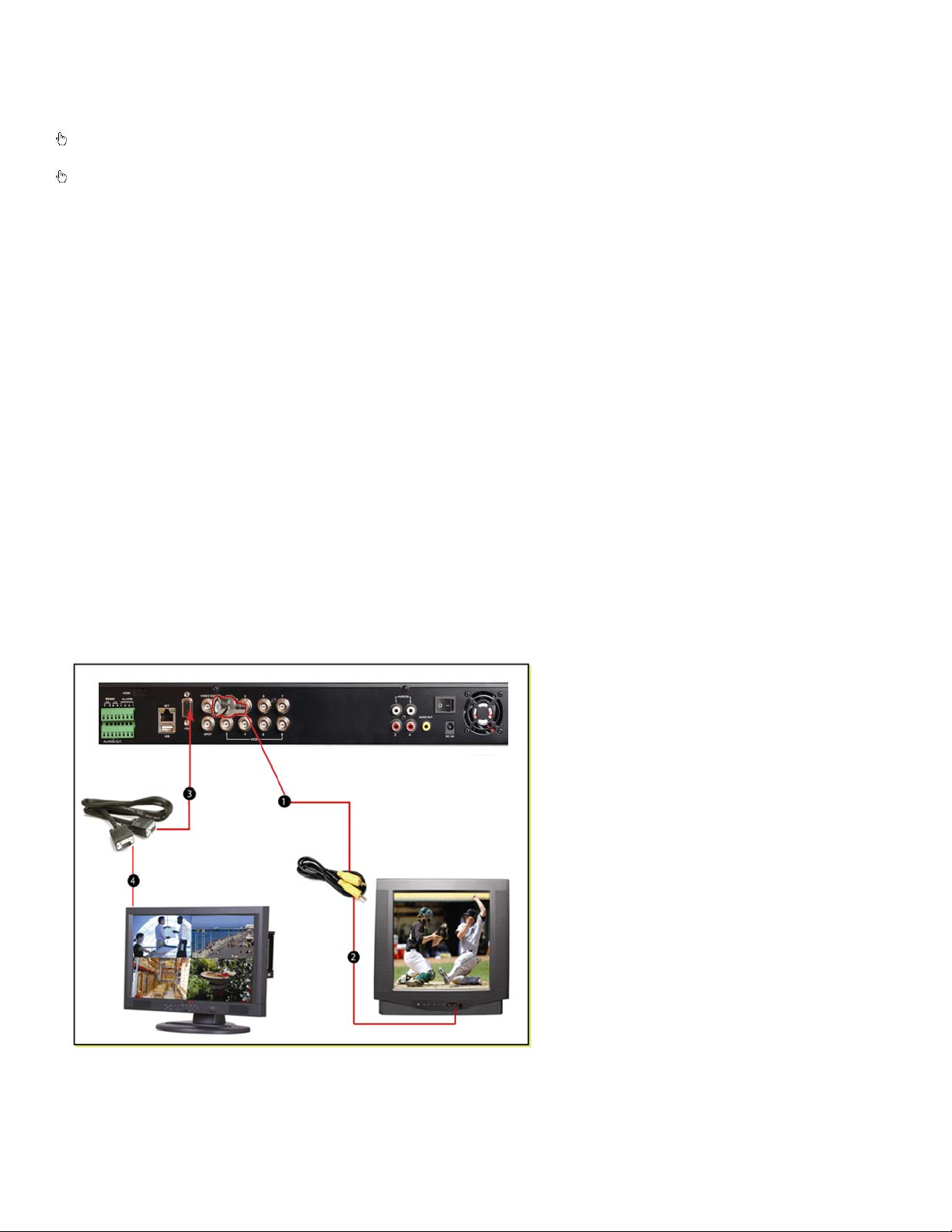
2. GETTING STARTED
1. Attach RCA cable to DVR
Attach the other end of the
RCA cable to a video in port
Attach one end of the VGA
included) to the
Attach the other end of the
VGA cable to a VGA port on
Check the unit and the accessories immediately af ter opening your system .
Please disconnect the po wer bef ore connecting to other devices.
2.1 Connecting to a monitor or TV
The primary display on th e DVR is VGA. To use with a VGA monitor:
1. Plug t he VGA cab le (not included) to the VGA port on the DVR.
2. Connect t he ot her end of the VGA cable (not included) to the monit or.
To use with a TV:
1. Plug the VGA cab le (not included) to the VGA port on the DVR.
2. Connect t he ot her end of the VGA cable (not included) to a VGA monitor.
3. Go to the login screen on the VGA monitor and log in t o t he DV R.
4. Attach the RCA cable from the DVR to the RCA video in port on the TV .
5. Hold d own the ESC button on the D VR for 10 seconds to transfer the video feed from the VGA monitor to the
TV.
6. You will now be able to view the cameras and access the menus on the TV but not the VGA monitor.
NOTE: You cannot view the cameras and control the menu on a TV and VGA monitor at the same time. Please note
that you need to use a monitor that is 19” or larger.
video out port using a RCA to
BNC adapter
2.
on the TV
3.
cable (not
VGA port on the DVR.
4.
the monitor
6
Page 8
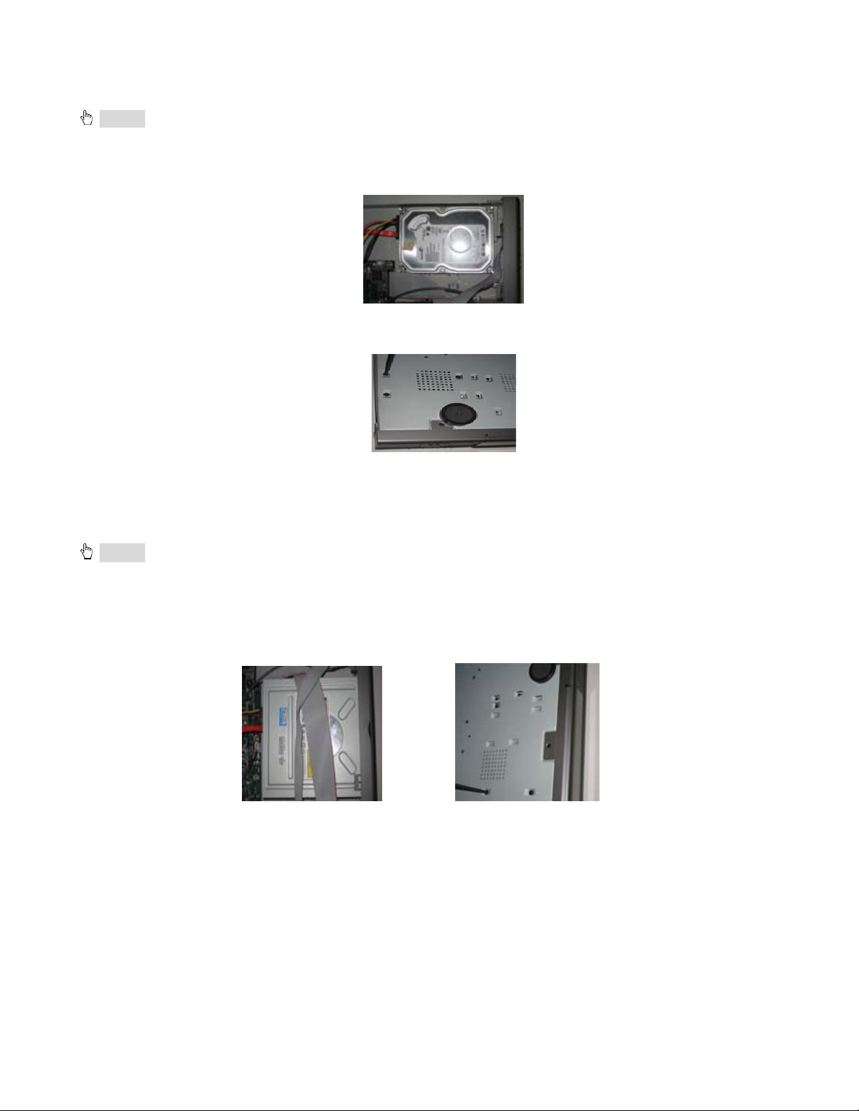
2.2 Installing Hard Drive
Notice: 1. This DVR supports two SATA hard drivers or one SATA hard drive plus one DVD-RW Writer.
2. Please calculate HDD capacity according to the recording setting. Please refer to “Appendix B Calculate
Recording Capacity”.
Step1: Unscrew and Open the top cover
Step2: Connect the power and data cables. Plac e the HDD onto the bottom case as below.
Fig 2.1 Connect HDD
Step3: Scr ew t he HDD as below .
Note: For the convenience t o install, please connect t he pow er and data cables firstly, and then screw to fix.
Fig 2.2 Screw in the HDD
Note: For easier installation, please connect the power and data cables first, and then screw the HDD to
base.
2.2.1 Install DVD Writer
Notice: 1. The writer should be on the compatible devices we recommend. Please refer to “Appendix C
Compatible Devices”. Others may work, but these are the only ones we have tested.
2. This device is only for backup
Step1: Unscrew and Open the top cover
Step2: Connect the power and data cables. Plac e the DVD writer onto the bottom case as shown in Fig 2.3.
Step3: Scr ew in t he DVD writer in Fig 2.4:
Fig 2.3 Connect the DVD Writer Fig 2.4 Screw in the Wri ter
7
Page 9

2.3 Front Panel Descriptions
Item
1
Power indicator, when connection , the light is
blue
1
When HDD is writing and reading , the light is
blue 1 Network Status
When access to networ k , the lig ht is bl ue
1
Backup Status
When backup files and dat a, the light is blue
1
Play Status
When playing video, the light is blue
1
REC Status
When recording, the light is blue
2
1. Enter menu in live
2. Increase the value in setup
3
P.T.Z.
Enter PTZ mode in live
4
Audio
Live or Mute Audio
5
1. Decrease the value in setup
2. Enter backup mode in liv e
6
Info
System Information
7
1. Enter search mode
2. ZOOM function enables at PTZ mode.
8
1. Quit play mode
2. Exit the current interfac e or s t at us
9
FF
Fast Forward
10
1. Reverse
2. SPEED function enables at PTZ mode
11
1. Quit play mode
2. Pause Playback
12
1. Record manually
2. FOCUS function enabl es at PTZ mode.
13
1. Change direction to select it ems.
2. Change screen display to 1/ 4/ 9/16 mode.
14
Enter button
Confirm selection
15
IR Sensor
For remote controller
16
To connect external USB devices like USB
flash, USB HDD for backup or updat e firmware.
Fig 2.5 Front P a nel
Name Description
Power Status
HDD Status
MENU/+
BACKUP/-
SEARCH/ZOOM
STOP/ESC
REVSPEED
STOP/Pause
RECORD/FOCUS
Direction/Multi-screen
USB port
8
Page 10
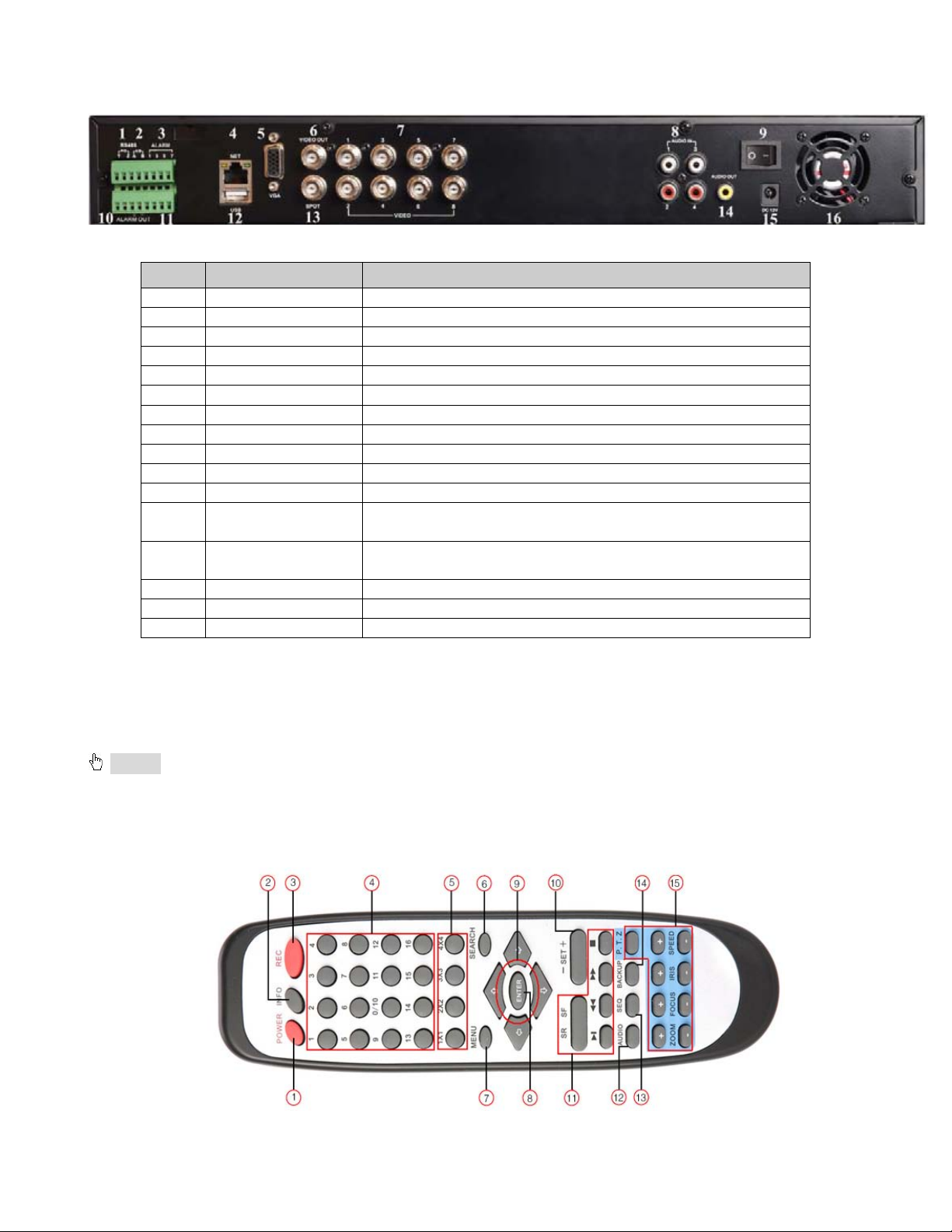
2.4 Rear Panel Layout
1
PTZ
Connect to speed dome. Y mean s “+”, Z means “-”
2
K/B
Connect to PTZ keyboard
3
ALARM IN
Connect to external senso r s 1-8
4
NET
Network port
5
VGA port
VGA output, connect to monitor
6
Video out
Connect to TV/monitor
7
Video in
Video input channels from 1-8
8
Audio in
4 Channels Audio input
9
POWER SWITCH
Power on/off
10
+ 5V and GND
+5 V and Grounding
11
ALARM OUT
1-ch relay output. Connec t to external alarm.
To connect external USB devices li ke US B flash, USB HDD
for backup or update firmw ar e.
Connect to monitor as an AUX output channel by channel.
Only video display, no menu
14
Audio out
Audio output, connect to amp l ified speaker
15
POWER INPUT
DC12V
16
FAN
For cooling the device
Item Name Description
12 USB port
13 Spot out
2.5 Remote Control
Uses two AAA size batteries, t o install batteries:
Step1: Open the batt er y cover of the Remote Control
Step2: Insert batteries. Position the poles (+ and -) correctly
Step3: Replace the battery cover
Notice: If the remote does not work:
1. Check batteries poles
2. Check the remaining charge in the batteries
3. Check to see if IR controller sensor on DVR is blo c k e d
If it still doesn't work, contact the Q-See customer service dept to replace the r em ot e cont r ol.
The interface of remote controller is shown in Fig2.6 Remote Controller.
Fig 2.5 Rear Panel
Tab 2.1 Back Panel Ports
9
Page 11

Fig 2.6 Remote Control
1
Power Button
Stops firmware so that y ou can pow er down DVR
Get information about the DVR like firmware version, HDD
information
3
REC Button
To record manually
4
Digital Buttons
Input numbers or choose ca mera
5
Multi Screen Button
To choose multi screen dis play mode
6
SEARCH Button
To enter search mode
7
MENU Button
To enter menu
8
ENTER Button
To confirm the choice or setup
9
Direction Button
Move cursor in setup or move PTZ camera
10
+/- Button
To increase or decrease t he value in setup
Playback Control
Button
12
AUDIO Button
To enable audio output in live mode
13
Auto Dwell Button
To enter auto dwell mode, display screens in se quence
14
BACKUP Button
To enter backup mode
To control PTZ camera:
Move camera/ZOOM/FOCUS/IRIS/SPEED control
Item Name Function
2 INFO Button
11
To control playback, Fast forward/rewi nd/stop/single frame play
15 PTZ Control Button
Operation procedure to control multiple DVRs with same remote control
The device ID of the DVR is 0. When using remote control to co ntrol a single DVR, it’s not necess arily to reset the
device ID; when controlling multiple D VR wit h remote controller, please refer to below steps:
Step1: Activate remote control to control DVR: enable DVR: Point the IR sensor of the remote control at the IR
receiver that on the front panel of the DVR, press the number key 8 twice, th en input device ID (Range from:
0-65535; the default device ID is 0.) with another digital number: 0-9, after that, press ENT ER button to confirm.
Step2: User can check the device ID by entering into System configurationBasic configurationdevice ID.
User also can set other DVR with the same device ID. For easier operation, we don’t recommend user set the
device ID too long.
Step3: To cancel a device ID: Point the IR sens or o f the re mote contro l at the IR receiver that is on the front pa nel,
press the number key 8 twice, then input the device ID that needs to be cancelled, press ENTER button to
confirm. After that, the DVR will not be controlled by remote control.
2 6 Control with Mouse
2.6.1 Connect Mouse
DVR supports USB mo use through the port on the rear panel, please refer to Fig 2.4 Number 5.
Notice: If mouse is not detected or doesn't work, check below steps:
1. Make sure the mouse plugs in the USB mouse port on the back of the DVR, not the front panel port.
2. Try a different mouse
10
Page 12

2.6.2 Use Mouse In Live:
Double-click left button on one camera to be full screen display. Double-click again to return to the previous screen
display.
Click right button to show the c ont r ol b ar at the bottom of the screen as Fig 4-1 main menu tool bar
Click right mouse again to hide t he control bar.
In Setup:
Click left button to enter. Click right button to cancel setup, or return to t he pr evious screen.
If you want to input values, move cursor to the blank and click. An input window will appear as shown in Fig2.6. It
supports numbers, letters and symbols.
Fig 2.6 Numbers and Letters Input Window
Users can change some values by the wheel, such as time. Move cursor onto the value, and rol l t he w heel w hen t he
value blinks.
Also supports mouse drag. I.e. Set motion detection area: click customized, hold left button and drag to set motion
detection area. Set schedule: hold left button and drag t o set schedule time
In playback:
Click left button to cho ose the options. Click right but t on t o r et ur n t o liv e view.
In backup:
Click left button to cho ose the options. Click right button to return to previous picture.
In PTZ control :
Click left button to cho ose the buttons to control the PTZ. Clic k r ight but t on t o return to live view.
Notice:
Mouse is the default tool for all the operations bel ow unles s ot her wi se not e d.
11
Page 13

3. BASIC FUNCTION
3.1 Power On/Off
Before you power on the unit, pl ease make sure all the connections are good.
3.1.1 Power On Step 1: Connect the power supply; switch on the p ower button near the power port on t he r ear panel Step 2: The firmware will be loaded, and the pow er indicator will display blue Step 3: At start up, a WIZZARD dialogue box will pop-up (re fer t o picture below) displaying time zone and time setup
information.
After the device powers o n, if there is no menu or only disp lays live imag e, user can hold dow n ESC b utton t o swit ch.
Notice: this unit can only display menu on VGA monitor or BNC monitor one at a time. If there is live image
display without menu display, please check to see if other monitoring device has menu display first, or hold
down ESC key to wait for login dialog box to appear.
3.1.2 Power Off
User can power off the d evice by using remote control, keyboard or mouse.
By Remote Control:
Step 1: Press Power button, the Shut down window will appear, click OK, the unit will power off after firmware is s hut
down.
Step 2: Disconnect the power. By Keyboard and Mouse:
Step 1: Enter into
Menu, then select “Syst em Shut Down” icon, the Shut dow n w indow w ill appear
Step 2: Click OK, the unit will power off after firmware is shut down.
Step 3: Disconnect the power.
12
Page 14

3.2 Login
Symbol
Meaning
Symbol
Meaning
Manual record or time
recording
Alarm
recording
Yellow
Motion detection recordin g
Figure icon
Motion event
User can login and logout of the DVR sy ste m. User cann ot do any ot her opera tions ex cept c hang in g the multi-screen display once logout. Admin has full control over DVR.
Fig 3-1 Login
Notice: the default user name and password is “admin” and 123456”
For information on how to change password, add or delete users please refer to Section 4.7 User
management configuration.
3.3 Live Preview
The explanation of symbo ls in the live preview interface:
Green
Fig 3-2 Live Preview Interface
Red
13
Page 15

3.3.1 Live Playback
Click the Play
screen.
button to playback the record. Refer to Figure3-3. User can operate by clicking the buttons on the
Fig 3-3 Live Playback
14
Page 16

4. MAIN MENU SETUP GUIDE
Click right mouse or press ESC button on the front panel, the control bar will display on the bottom of the screen, refer to Fig 4-1:
Fig 4-1 Main Menu Toolbar
Click icon beside the screen display mode, a channel select dialog will appear as below:
Take 8-channel DVR for example: user can tick off 8 channels form 1-ch to 8-ch at random to display the
live pictures. Then c lick
Click
icon, user can zoom in the live and playback images. When single image display, user can
butt on to confirm th e setting.
select zoom in area by dragging mouse.
Click the Menu
button, the interface will pop-up as shown in Fig 4-2; press MENU button on the front
panel or remote contr ol will also display the main interface.
Fig 4-2 Main Menu
15
Page 17

4.1 Basic Configuration
Basic configuration includes three sub menus: system, date& time and DST.
4.1.1 Setup
Step1: Enter into Setup configurationbas i c configurationsetup; refer to Fig 4-3:
SETUP
Fig 4-3 Basic Configuration
Step2: In this interface user can setup the device name, device ID, video format, max network users, VGA resolution
and language. The explanations for each d isp lay are shown below:
Device name: the name of the device. It will display on the client end or CMS and help user to recognize the
device remotely.
Video format: two modes: PAL and NTSC. User can select the video format according to that of camera, in
USA and Canada we use NTSC camer as.
Password Check: if you enable this option, user needs t o input user na me and p asswor d to do corresp onding
operations in system configuration.
Show time: display time in live view.
Show wizard: check this item, an opening wizard will display with time zone and time setup information
Max network users: set t he m aximum number of network connections
VGA resolution: the resolution of live display interface, options are: VGA800*600, VGA1024*768,
VGA1280*1024 and CVBS
Note: Switching between VGA and CVBS will change the menu output mode, please connect to relevant monitor, VGA for VGA monitor, CVBS for TV or monitor that is connected using BNC adapter. Language: setup the menu language. Note: after changing the language and vi deo o ut put, t he device needs to restar t .
16
Page 18

4.1.2 Time & Date Step 1: Enter into system configurationbasic configurat iontime & date; refer to Fig 4-4:
Fig 4-4 Basic Configuration-Time & Date
Step 2: Set the date format, time format, time zone in this interface; Checkmark “sync time with NTP server” to
refresh NTP server date; user also can adjust system date m anually
Step 3: Click “default” button to restore default settings; click “apply” button to save the settings; click “exit” button to
exit current interface.
4.1.3 DST Step1: Enter into system configurationbas ic configurationDST; refer to Fig 4-5:
Fig 4-5 Basic Configuration-DST
Step 2: In this interface, you can enable daylight s aving time, time offset, mod e, s tart & end month/week/dat e, et c .
Step 3: Click “default” button to restore default settings; click “apply” button to save the settings; click “exit” button to
exit current interface.
17
Page 19

4.2 Live Configuration
Live configuration include s four submenus: live, host monitor, SPOT and mask.
4.2.1 Live
In this interface, user can set up camera names, adjust colors: br ightness, hue, saturation and cont r ast .
Step 1: Enter into system configurationlive configurationlive; refer to Fig 4-6:
Fig 4-6 Live ConfigurationLive
Step 2: Checkmark camera name; click “sett i ng” button, a window will pop-up show n as Fig 4-7:
Fig 4-7 Live-Color Adjustment
Step 3: In this interface, user can adjust brightness, hue, saturation and contrast in live view; click “default” button to
restore default settings, cli ck “OK” button to save the settings.
Step 4: User can setup all channels with same parameters, checkmark “al l”, t hen do r elevant setup.
Step 5: Click “default” button to restore default settings; click “apply” button to save the settings; click “exit” button to
exit current interface.
18
Page 20

4.2.2 Host Monitor Step 1: Enter into system configurationlive configurationhost monitor; refer to Fig 4-8:
Fig 4-8 Live Configuration-Host Monitor
Step 2: Select split mode: 1×1, 2×2, 2×3, 3× 3, and channel
Step 3: Dwell time: the time interval for a cert ain picture display before switching to next picture display
Step 4: Select the split mode, then s etup curre nt pi ctur e group. Clic k
button to setup the previous c han nel gr oup s
of pictures, click button to set latter channel groups of pictures.
Step 5: Click “default” button to restore default settings; click “apply” button to save the settings; click “exit” button to
exit current interface.
NOTE: If you have dual monitors Hos t m onitor needs to be main monitor.
4.2.3 SPOT Step 1: Enter into system configurationlive configurationSPOT; refer to Fig 4-9:
Fig 4-9 Live Configuration-SPOT
Step 2: Select split mode: 1×1 and channel
Step 3: Dwell time: the time interval for a cert ain picture display before switching to the next picture display.
Step 4: Select the split mode, then s etup curre nt pi ctur e group. Clic k
button to setup the previous c han nel gr oup s
of pictures, click button to set the latter channel groups of pictures.
Step 5: Click “default” button to restore default setting; click “apply” button to save the setting; click “exit” button to
exit current interface.
To activate this setting, go to the main camera screen and click on the Dwell icon (Fig 4-1). This will make the camera
rotate based on the setti ng in Main Monitor.
19
Page 21

4.2.4 Mask
User can setup private ma s k ar ea on t he live image picture, maximu m of thr ee areas.
Fig 4-10 Live Configuration-Mask
Setup Mask Area: click Setting button, enter i nt o l ive image and press left mouse but t on and drag mouse to set
mask area, refer to picture below. C lic k Apply button to save the setting.
Delete Mask Area: sel ect a certain mask area, click left mouse button to delete that mask area, click Apply
button to save the setting.
Setup Mask Area
Live Image Mask Area
20
Page 22

4.3 Record Configuration
Parameter
Meaning
Record
Switch Record on or of f
Audio
Enable live audio recording
Redundancy
Record configuration inc lu des f iv e s ub menus: enable, record bit rate, t i me, r ecycle record and stamp.
4.3.1 Enable Step 1: Enter into system configurationrecord con figur at ionenable; refer to Fig 4-11:
Fig 4-11 Record Configuration-Enable
Step 2: Checkmark record, audio and record time
Step 3: User can setup all channels with same parameters, checkmark “al l”, t hen do r elevant setup.
Step 4: Click “default” button to restore default setting; click “apply” button to save the setting; click “exit” button to
exit current interface.
Definitions and descriptions of Record:
21
Page 23

4.3.2 Record stream
Parameter
Definition
FPS
Range from 1-30 (NTSC) 1-25 (PAL)
Rate
Resolution
CIF or D1 Each camera can use either resolution option
Quality
The quality of recorded images. The higher the value, the clearer the recorded image is. Six options: lowest, lower, low, medium, higher and highest.
Encode
VBR and CBR
Max bit
2 Mbps
Step 1: Enter into system configurationrecord con figur at ionrecord bit rate; refer to Fig 4-12:
Fig 4-12 Record Configuration-Record Bit Rate
Step 2: Setup rate, resolution, quality, encode and max bit stream
Step 3: User can setup all channels with same parameters, checkmark “A ll”, t hen t o do r el evant setup.
Step 4: Click “default” button to restore default setting; click “apply” button to save the setting; click “exit” button to
exit current interface.
Note: if you set a value that is higher than maximum supported by the device, the value will be adjusted automatically.
Definitions and descriptions of Record stream:
Range from: 1-30(NTSC)1-25(PAL)
Range from: 64 Kbp s、128 Kbps、256 Kbps、512 Kbps、768 Kbps、1Mbps、
stream
22
Page 24

4.3.3 Time Step 1: Enter into system configurationrecord con figur at ion time; refer to Fig 4-13:
Fig 4-13 Record Configuration-Time
Pre-alarm record time: set the record time before event happen i.e. record time before motion detection or
sensor alarm is triggered.
Post-alarm record: set the post recordi ng ti me aft er the alar m is finishe d, fiv e options : 10s, 15s , 20s, 30 s and
60seconds.
Expire time: the hold time of saved records. When the set date has passed, the record files will be deleted
automatically.
Step 2: User can setup all channels with same p ar ameters, checkmark “all”, t hen t o do r elevant setup.
Step 3: Click “default” button to restore default setting; click “apply” button to save the setting; click “exit” button to
exit current interface.
4.3.4 Recycle Record Step 1: Enter into system configurationrecord con figur at i onrecycle record; Step 2: Checkmark recycle record, the recycle record function will be enabled, it will overwrite the earlier recorded
files and keep recoding w hen HDD is full; if not enables the DVR will stop recording when HDD is ful l.
Step 3: Click “default” button to restore default setting; click “apply” button to save the setting; click “exit” button to
exit current interface.
23
Page 25

4.3.5 Stamp
Stamp:User can display the channel name and time stamp on v ideo.
Step 1: Enter into system configuration record configuration stamp; refer t o Fig 4-14:
Fig 4-14 Record Configuration-Stamp
Step 2: Checkmark camera name, time stamp; click Set button, user can use cursor to drag the camera name and
time stamp to rando m po sitions, refer to below Figures:
Before Drag After Drag
Step 3: User can setup all channels with same parameters, checkmar k “all”, t hen t o do r elevant setup.
Step 4: Click “default” button to restore default setting; click “apply” button to save the setting; click “exit” button to
exit current interface.
4.4 Schedule Configuration
24
Page 26

Schedule configuration includes three sub menus: schedule, motion and alarm.
4.4.1 Schedule Step 1: Enter into system configurationschedule conf igurationschedule; refer to Fi g 4-15:
Fig 4-15 Schedule Configuration-Schedule
Step 2: Select channel, double-click and a dialog box will pop-up shown as Fig 4-16, user can edit week sched ul e:
Fig 4-16 Schedule-Week Schedule
① Click “add” button to add a certain day schedule; clic k “d el ete” button to delete the selected schedule;
Copy: user can copy the specify sc hedule to other dates.
Click “OK” button to save the s et t ing, click “Exit” button to exit curre nt int er f ace.
② User can apply the schedule setting of certain channel to other or all channels, just only select channel
and click “Copy” button.
Step 3: Click “default” button to restore default setting; click “apply” button to save the setting; click “exit” button to
exit current interface.
4.4.2 Motion Step 1: Enter into system configurationschedule conf igurationmotion; refer t o Fig 4-17:
25
Page 27

Fig 4-17 Schedule Configuration-Motion
Step 2: The setup steps of motion are simi lar t o schedule; user can refer to 4.4.1 Schedule for details.
Note: the default schedule of motion detection is all of the time, that is, the color of schedule interface is all
blue.
4.4.3 Sensor Step 1: Enter into system configurationschedule conf igurationalarm; refer to Fig 4-18: Step 2: The setup steps of alar m are si m il ar t o schedule; user can refer to 4.4.1 Schedule for details. Note: the default schedule of motion detection is all of the time, that is, the color of schedule interface is all
blue.
Fig 4-18 Schedule Configuration-Sensor
4.5 Alarm Configuration
Alarm configuration includes five sub menus: sensor, motion, video loss, other alarm and alarm out.
26
Page 28

4.5.1 Sensor (to setup optional external motion sensors)
Sensor includes three sub menus: basic, alarm handling and schedule.
① Basic
Step 1: Enter into system configurationalarm configurationsensorbasic; r efer t o Fig 4-19:
Fig 4-19 Alarm Configuration-Sensor Basic
Step 2: Enable sensor alarm, set the alarm type according to triggered alarm type. Two opt ions: NO ( nor ma l ly open)
and NC (normally closed).
Step 3: User can setup all channels with same parameters, checkmark “al l”, t hen t o do relevant setup.
Step 4: Click “default” button to restore default setting; click “apply” button to save the setting; click “exit” button to
exit current interface.
② Alarm Handling
Step 1: Enter into system configurationalarm configurationsensoralarm handling; refer to Fig 4-20:
Fig 4-20 Alarm Configuration-Sensor-Alarm Handling
Step 2: Select hold time, click Trigger button, and a dialog bo x w il l pop-up shown as Fig 4-21:
27
Page 29

Fig 4-21 Alarm Handling-Trigger
Step 3: Checkmark Buzzer, there will be triggered buzzer alarm out;
Full screen alarm: whe n t r iggered alarm, there will pop up an alar m full s cr een;
To alarm out: checkmark the channel, there will be triggered alarm out on the designated channel. Click OK
button to save the setting; clic k Exit button to exit the current inter face.
To record: checkmark recoding channels, it will record from the camera when alarm is triggered. Click OK
button to save the setting; clic k Exit button to exit the current inter face.
To P.T.Z: set linked preset and cruise for alarm. User can select any channel or multiple channels as linked
channels. Click OK button to save the setting; click Exit button t o exit t he cur rent interface.
Step 4: User can setup all channels with same parameters, checkmark “al l”, t hen t o do r elevant setup.
Step 5: Click “default” button to restore default setting; click “apply” button to save the setting; click “exit” button to
exit current interface.
③ Schedule
Step 1: Enter into system configurationalarm configurationsensorschedule; refer to Fig 4-22:
Fig 4-22 Sensor-Schedule
Step 2: The setup steps of sensor schedu le are similar to schedule; user ca n r efer t o 4. 4. 1 Schedule for details.
Note: the default schedule of motion detection is all of the time, that is, the color of schedule interface is all
blue.
4.5.2 Motion
Motion includes two sub me nus: motion and schedule.
28
Page 30

① Motion
Step 1: Enter into system configurationalarm configurationmotion; refer to Fig 4-23:
Fig 4-23 Alarm Configuration-Motion
Step 2: Enable motion alarm, set alarm hold ti me which means t ime interval b etw een two consecut ive motion ev ents.
If there is other motion detected during the interval period which is considered continuous movement; it will be
included in the curre nt f il e, ot her w ise, it will be considered the start of a new m ot ion file. Click T r igger button, a dialog
box will pop-up:
Step 3: The setup steps of motion trigger are similar to alarm handling; user can refer to Chapter 4.5.1 Sensor
alarm handling for more details.
Step 4: Click Area button, a dialog box will pop-up shown as Fig 4-24:
Fig 4-24 Motion-Area
Step 5: In the Area interface, user can drag slide bar to set the sensitivity value (1-8), the default value is 4. The
higher the value the higher sensitivity you get. Since the sensitivity is influenced by color and time (day or night),
29
Page 31

user can adjust its value according to the practical conditions; click icon, set the whole area as detection area;
click
motion area are suitable to current conditions(refer t o follow ing pic t ur e); Click
icon, the set detection area will be cleared; click icon, user can test whether the sensitivity value and
icon, to save the setting; click
icon, exit current interface.
Note: when user drags mouse to set motion detection area, they have to click
icon to clear
current detection area fi r st , and then set the area.
Step 6: User can setup all channels with same parameters, checkmark “al l”, t hen t o do r elevant setup.
Step 7: Click “default” button to restore default setting; click “apply” button to save the setting; click “exit” button to
exit current interface.
② Schedule
Step 1: Enter into system configurationalarm configurationschedule; refer to Fig 4-25:
Fig 4-25 Alarm Configuration-Schedule
Step 2: The setup steps of alar m sche dule are similar to schedule; user can refer to 4.4.1 Schedule for details.
Step3: user can set up all channels with same parameters, tick off “all”, then to do relevant setup.
Step4: click “default” button to resort de fault setting; click “apply” button to save the setting; click “exit”
button to exit current interface.
4.5.3 Video Loss
30
Page 32

Step 1: Enter into system configurationalarm configurationvideo loss; refer to Fig 4-27:
Fig 4-27 Alarm Configuration-Video Loss
Step 2: The setup steps of video loss trigger are fam il iar w it h al arm handling; user can refer to Chapter 4. 5. 1 Sensor
alarm handling for more details.
Step 3: User can setup all channels with same parameters, checkmark “al l”, t hen t o do r elevant setup.
Step 4: Click “default” button to restore default setting; click “apply” button to save the setting; click “exit” button to
exit current interface.
4.5.4 Other Alarm
Fig 4-28 Other Alarm
Step 1: Enter into system configurationother alarm; r ef er t o Fig 4-27:
Step 2:
select a hard disk in the pull down list box, when the disk capacity is lower than that value, there will
appear some text information on the lower right of the live image.
IP conflict: if there is an IP address conflict within the same network, the d evice wi ll auto send an e mail to user s
designated mailbox to notify the conflict details.
Disconnect: if the disconnect happen, the device will auto send disconnection information to users designated
mailbox.
Step 3: Click “default” button to restore default setting; click “apply” button to save the setting; click “exit” button
to exit current interface.
4.5.5 Alarm Out
31
Page 33

Alarm out includes three sub m enus: alarm out, schedule and buzzer
① Alarm out
Step 1: Enter into system configurationalarm out; refer t o Fig 4-28:
Fig 4-28 System Configuration-Alarm Out
Step 2: In this interface, set relay alarm out name, select hold time which means the interval time between the two
consecutive alarms.
Step 3: User can setup all channels with same parameters, checkmark “al l”, t hen t o do r elevant setup.
Step 4: Click “default” button to restore default setting; click “apply” button to save the setting; click “exit” button to
exit current interface.
② Schedule
Step 1: Enter into system configurationschedule;
Step 2: The setup steps of alar m out schedule are similar to schedule; user can refer to 4.4.1 Schedule for details.
Note: the default schedule of motion detection is all of the time, that is, the color of schedule interface is all
blue.
③ Buzzer
Step 1: Enter into system configurationbuzzer;
Step 2: Checkmark Buzzer, set buzzer alarm hold time
4.6 Network Configuration
Network configuration includes two submenus: networ k and network stream.
32
Page 34

4.6.1 Network
Parameter
Meaning
HTTP port
Port to access from IE browser. The default port is 80
Server
port
The port number for data. The default port is 6036
Static IP
IP address
The IP address of the DVR
Subnet
mask
The subnet mask of the serv er
Gateway
The gateway of the router
DNS
server
The address of DNS serv er
PPPoE
Step 1: Enter into system configurationnetwork conf igurationnetwork; refer t o Fig 4-29:
Fig 4-29 Network Configuration-Network
Step 2: HTTP port: the default value i s 80. If this valu e is changed, us er needs to add t he port numb er when ty ping IP
address in IE address blank .i.e. set HTTP port to 82, IP address: http://192.168.0.25, user needs to input this
address: http://192.168.0.25:82 into IE browser. Server port: communication port
Step 3: Checkmark the "Obtain IP address automatically", the device will receive IP address, subnet mask, gateway
IP from the router the D V R is attached to.
Step 4: Enable PPPOE, user can directly connect the DVR to internet via ADSL, then input the user name and
password; click TEST button to test the effectiveness of supplied information. You will need to get the account
information from your internet service provider.
Step 5: Enable DDNS server: user needs to input user name, password and host domain name of the registered
website, click TE ST to test the effectiv eness of information you input.
Step 6: Click “default” button to restore default setting; click “apply” button to save the setting; click “exit” button to
exit current interface.
3. Defi nitions and descri pt ions of network configuration:
33
 Loading...