


ISIS Series
QSC ISIS Series, ISIS 102W, ISIS W-102M, ISIS W-102W, ISIS 102M User Manual
...
ISIS-Series Loudspeakers
ISIS W-102M and ISIS 102M 10” two-way, medium dispersion
ISIS W-102W and ISIS 102W 10” two-way, wide dispersion
ISIS W-122M and ISIS 122M 12” two-way, medium dispersion
ISIS W-152M and ISIS 152M 15” two-way, medium dispersion
User Manual
EN
*TD-000119-00*
TD-000119-00 rev.B

EN
Important Safety precautions
& Explanation of symbols
1- Read these instructions.
2- Keep these instructions.
3- Heed all warnings.
4- Follow all instructions.
5- Clean only with a dry cloth.
6- Install in accordance with QSC Audio Product’s instructions and a licensed, professional engineer.
7- Do not install near any heat sources such as radiators, heat registers, stoves, or other apparatus (including amplifiers) that
produce heat.
8- Only use attachments/accessories from QSC Audio Products, Inc.
9- Use only with mounts or brackets specified by QSC Audio Products.
10- Refer all servicing to qualified personnel. Servicing is required when the apparatus has been damaged in any way.
The exclamation point within an equilateral triangle is intended to alert the user to the presence of important operating and
maintenance (servicing) instructions in this manual.
WARNING! Before placing, installing, rigging, or suspending any speaker product, inspect all hardware, suspension, cabinets, transducers, brackets and associated equipment for damage. Any missing, corroded, deformed or non-load rated component could significantly reduce the strength of the installation, placement, or array. Any such condition severely reduces
the safety of the installation and should be immediately corrected. Use only hardware which is rated for the loading conditions of the installation and any possible short-term unexpected overloading. Never exceed the rating of the hardware or
equipment. Consult a licensed, professional engineer when any doubt or questions arise regarding a physical equipment
installation.
Warranty (USA only; other countries, see your dealer or distributor)
Disclaimer
QSC Audio Products, Inc. is not liable for any damage to amplifiers, or any other equipment that is caused by negligence or improper
installation and/or use of this loudspeaker product.
QSC Audio Products 3 Year Limited Warranty
QSC Audio Products, Inc. (“QSC”) guarantees its products to be free from defective material and / or workmanship for a period of three
(3) years from date of sale, and will replace defective parts and repair malfunctioning products under this warranty when the defect
occurs under normal installation and use - provided the unit is returned to our factory or one of our authorized service stations via prepaid transportation with a copy of proof of purchase (i.e., sales receipt). This warranty provides that the examination of the return product must indicate, in our judgment, a manufacturing defect. This warranty does not extend to any product which has been subjected to
misuse, neglect, accident, improper installation, or where the date code has been removed or defaced. QSC shall not be liable for incidental and/or consequential damages. This warranty gives you specific legal rights. This limited warranty is freely transferable during
the term of the warranty period.
Customer may have additional rights, which vary from state to state.
In the event that this product was manufactured for export and sale outside of the United States or its territories, then this limited warranty shall not apply. Removal of the serial number on this product, or purchase of this product from an unauthorized dealer, will void
this limited warranty.
Periodically, this warranty is updated. To obtain the most recent version of QSC’s warranty statement, please visit www.qscaudio.com.
Contact us at 800-854-4079 or visit our website at www.qscaudio.com.
®
Speakon
2
is a registered trademark of Neutrik® and the names of Neutrik® products referenced herein are either trademarks and/or service marks of Neutrik®.
“QSC” and the QSC logo are registered with the U.S. Patent and Trademark Office
© Copyright 2003, QSC Audio Products, Inc.
QSC® is a registered trademark of QSC Audio Products, Inc.
All trademarks are the property of their respective owners.
Introduction
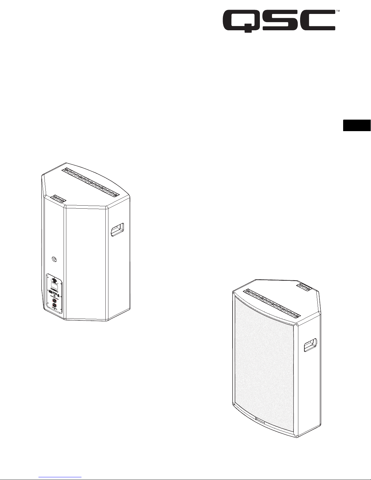
Thank you and congratulations on your purchase of QSC’s ISIS multipurpose loudspeakers. These products represent the state-ofthe-art in lightweight SR (sound reinforcement) loudspeaker systems. To get the most from your investment, we encourage you to
review this manual carefully.
The ISIS 102M, ISIS 102W, ISIS 122M, and ISIS 152M loudspeaker systems are full range, high output, two-way designs delivering superior sound quality and high SPL in a lightweight, all-weather cored composite enclosure.
The ISIS W-102M, ISIS W-102W, ISIS W-122M, and ISIS W-152M loudspeaker systems are wooden enclosure versions and are
essentially identical with the exceptions of weight and weather resistance. These models offer an economical alternative to the
cored composite enclosures in high quality 13 to 18 ply baltic birch.
Applications include flown arrays, yoke mounting, foldback stage monitors, and portable event use (pole mount). Hardware
options make the ISIS loudspeakers versatile and easy to reconfigure for mobile and touring sound companies. These loudspeakers make an excellent choice for a wide variety of SR applications.
Do not install wooden enclosure models in exterior environments unless fully shield from the weather.
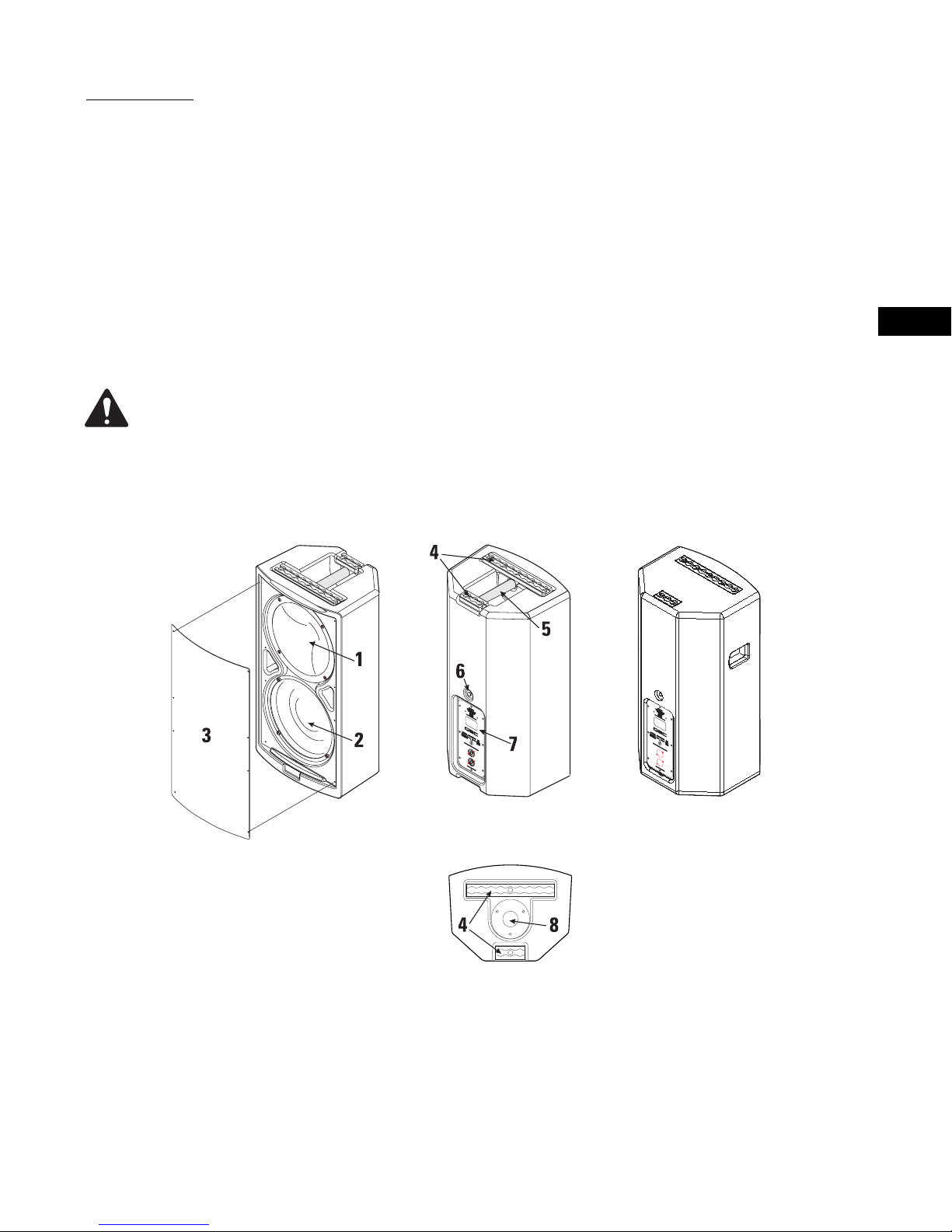
Product Features (ISIS 102M (handle on top) and ISIS W-102M (side recess) shown)
Note: Models featuring cored composite enclosures have a carrying handle on their top, whereas wooden enclosure models have
a handling recess on the side of the enclosure. A wooden enclosure is shown at the far right, below. Other views are of a cored
composite enclosure.
EN
1- High-frequency driver/waveguide assembly (102W waveguide differs)
2- Low-frequency driver
3- Removable metal/foam grill
4- Fly track (top and bottom of cabinet)
5- Carrying handle
6- Rear pick-point
7- Connection panel with two Speakon® connectors wired in parallel and crossover mode selector switch
8- Pole cup (bottom of cabinet)
Note- Standard model shown. Custom product options may include hardware and connector variations.
3
EN
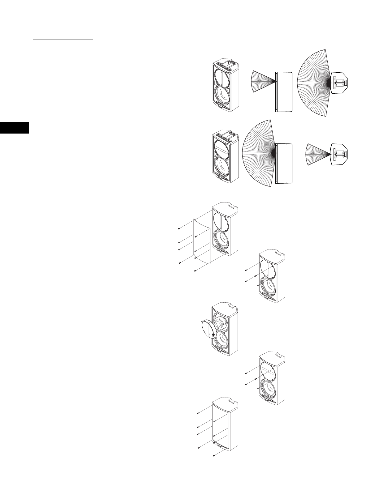
Coverage Angles
102M/122M/152M- These models are
equipped with 60° conical waveguides. HF
coverage remains constant regardless of
cabinet orientation.
102W- Before mounting the loudspeaker,
determine the mounting orientation and
desired coverage angles. As supplied from
the factory, the loudspeaker’s coverage
angles are 150° (horizontal) x 50° (vertical)
with the cabinet oriented vertically. The
waveguide can be rotated to interchange
the coverage angles.
Rotating the Waveguide to Alter
HF Coverage Pattern (102W only)
1- Remove the grill. It is held in place by
eight cap head screws.
2- Remove the four waveguide retaining
screws. A #2-size Phillips screwdriver is
recommended.
Waveguide slot vertically oriented: (102W
only; as shipped from
factory)
Waveguide slot horizontally oriented: (102W
only; requires
waveguide rotation)
3- Reach into the waveguide’s port and
pull gently to remove the waveguide. Be
careful not to damage the connections,
wiring, or the gasket between the
waveguide and the cabinet. The aluminum
spacer ring must remain in place.
4- Rotate the waveguide 90° clockwise or
counterclockwise and set it back in place.
Make certain the wiring is not stressed or
pulled loose from its connections when
rotating the assembly.
5- Before reinstalling the waveguide
mounting screws, lift the assembly a small
distance and make sure that the gasket
and spacer ring are properly in place.
Reposition, if required. Set the waveguide
in place and install the screws. We recommend the use of removable thread sealant
to prevent the screws from loosening. Do
not overtighten.
6- Replace the grill. We recommend the
use of removable threadlocker to prevent
the screws from loosening. Do not overtighten.
4
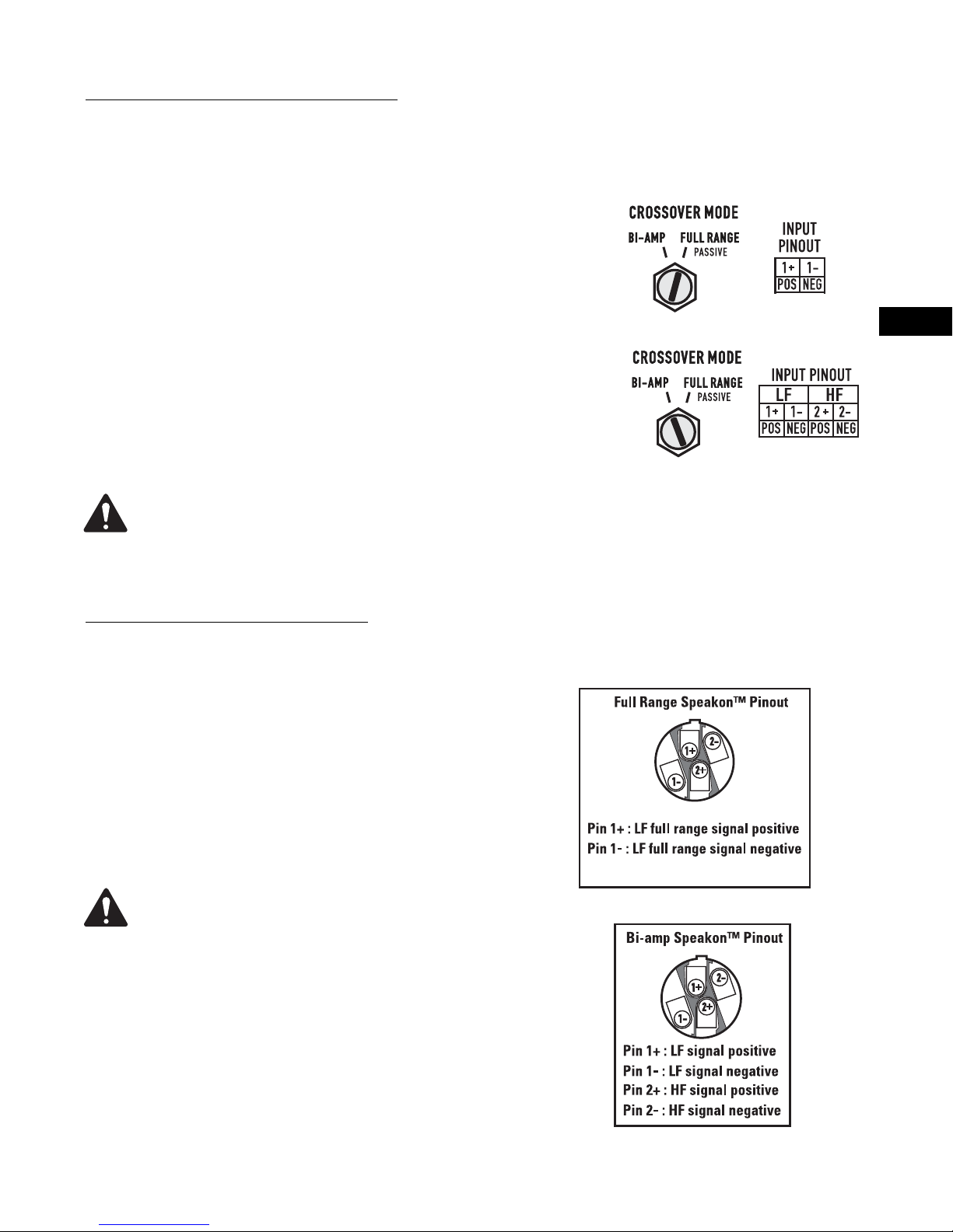
Select the Desired Crossover Mode
All models are equipped with a Crossover Mode switch.
Before using, set the Crossover Mode switch to the desired
position using a flat-tip screwdriver. The switch has a slotted shaft; insert the screwdriver tip into the slot and turn
the shaft so the slot points to the desired mode. Do not
change switch positions with power applied.
FULL RANGE: This setting uses the internal crossover network. Connect the full-range input signal to Speakon pins
1+ and 1-.
BI-AMP: This setting bypasses the internal crossover network and connects Speakon pins 1+ and 1- to the low-frequency (LF) driver and pins 2+ and 2- to the high-frequency
(HF) driver. Signal processing ahead of the amplifier is
required; the HF driver can easily be damaged if full range
program is applied! Use a four-wire cable and an amplifier
configured to operate in bi-amp mode.
BIAMP OPERATION- Signal processing ahead
of the amplifier is required; the HF driver can
easily be damaged if full range program is
applied!
Make the Required Connections
All models are equipped with two Neutrik NL4-series airtight Speakon connectors. The two connectors are wired in
parallel, allowing for multiple cabinets to be connected in
parallel by plugging one cabinet into another with a suitable
cable.
FULL RANGE
EN
BI-AMP
Connector pinout is determined by the Crossover Mode
switch setting. Full Range selection uses Speakon pins 1+
and 1-. Bi-amp selection uses pins 1+ and 1- for the LF
driver, 2+ and 2- for the HF driver. There are pinout charts
printed on the connector plate.
Maintain proper speaker and amplifier connection polarity throughout the entire system.
All positive-marked loudspeaker terminals
should be connected to positive-marked amplifier output terminals. This will provide the best
possible low-frequency output from your system.
Speakon plug pinouts- The Speakon plugs that are con-
nected to the loudspeaker cabinets should conform to the
pin outs shown at right. The connectors are shown from the
wire-insertion end and show the inside of the disassembled
Speakon plug.
5

Recommended Fastener Torque
Fly track to cabinet-4.52 Nm (40 in-lb)
Pole cup to cabinet- 1.92 Nm (17 in-lb)
Waveguide to cabinet- 1.92 Nm (17 in-lb)
LF driver to cabinet- 1.92 Nm (17 in-lb)
Grill to cabinet-1.01 Nm (9 in-lb)
Connector plate to cabinet-1.01 Nm (9 in-lb)
EN
All fasteners should be checked for tightness
before loudspeaker use. If any fastener is loose
or is removed for any reason, ensure it is
installed using a torque-limiting tool to avoid
cabinet damage. Fly track hardware is safetycritical and should be carefully checked before
suspending or rigging the cabinet.
6
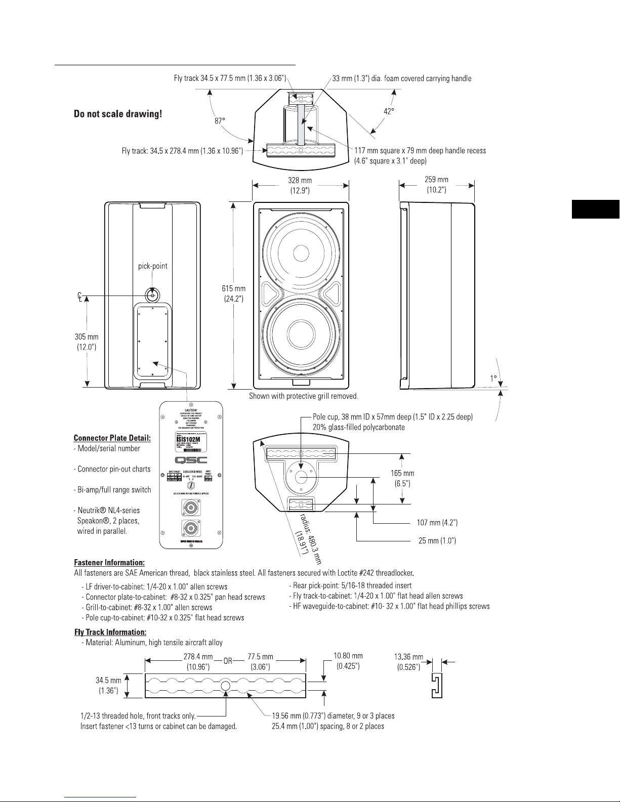
ISIS 102M Dimensions (ISIS 102W similar)
EN
Specifications are subject to change without notice.
7
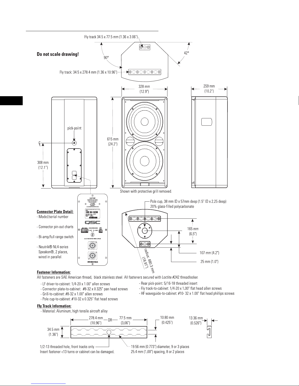
EN
ISIS W-102M Dimensions (ISIS W-102W similar)
Specifications are subject to change without notice.
8
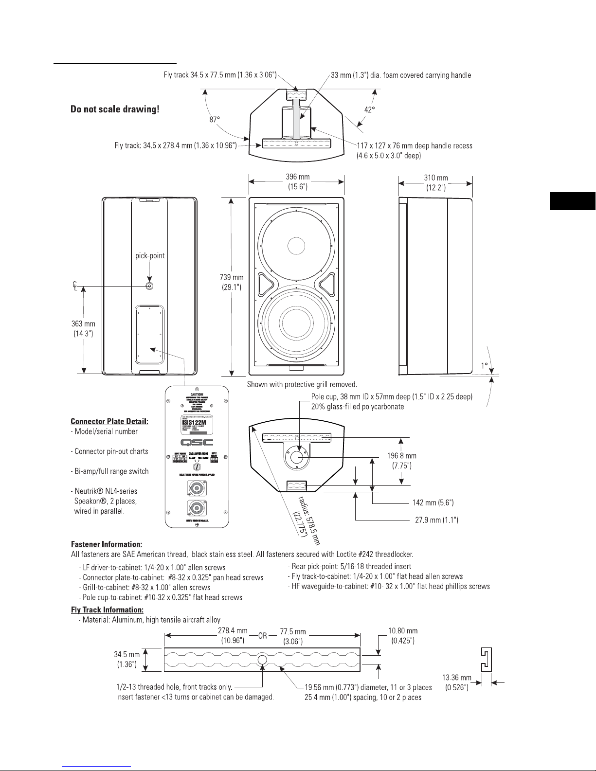
ISIS 122M Dimensions
EN
Specifications are subject to change without notice.
9
 Loading...