

Protherm Panther 24 KTV, Panther 24 KOV, 24(12) KTO, Panther 12 KTO, Panther 12 KOO Operation And Installation Manual
...Page 1

Operation and
Installation Guide
24 KTV / v.18
24 KOV / v.18
24(12) KTO / v.18
24(12) KOO / v.18
Wall-hang gas boiler
Output range 8,4 - 24,6 kW
Possibility of equithermal control
Panther
xxxxxxxxxx_00 - v.1 1/2007
EN
version
Page 2

Page 3

1
Panther 24 KTV / 24 KOV / 24(12) KTO / 24(12) KOO
The boiler’s Serial no. is shown on the plate which is attached to the front side of the
control panel. The control panel is accessible after removing the front cover.
In the section “Operating Instructions” you will fi nd description of the boiler’s main functions
and guidelines on how to handle the boiler safely. The section “Installation Instructions”
is for skilled workers only.
Obsah
Table of contents
Introduction ........................................... 2
OPERATING INSTRUCTIONS
Controls and signals ............................. 4
Selecting Read mode ........................... 5
Selecting Setup mode .......................... 5
Error codes ........................................... 7
Schematic diagram of boiler control ..... 8
Starting up and shutting down boiler .... 9
Boiler control ......................................... 9
Protection functions ............................. 10
Service and maintenance .................... 11
Warranty and warranty conditions ....... 12
Technical specifi cations ....................... 13
Connection dimensions ....................... 17
Usable overpressure into system ....... 18
INSTALLATION INSTRUCTIONS
Schematic diagram of boiler ............... 19
Introduction .......................................... 21
Delivery completeness ........................ 23
Preparing for boiler installation ............ 25
Installing the boiler ............................... 27
Air and combustion gas
passages (KTV, KTO) .......................... 30
Electrical connection of boiler .............. 35
Connection of boiler to hot water tank . 36
Converting to different fuel .................. 37
Electrical wiring diagram..................... 38
Page 4

2
1. The boiler and all the associated
equipment must be installed and used
in accordance with the installation
design, all the corresponding valid legal
prescriptions and technical norms and
with the manufacturer’s instructions.
2. The boiler may be installed only in an
environment for which it is designed.
3. After installation, the boiler may be put
into operation by an authorised service
organisation only.
4. The boiler complies with the prescriptions valid in the Slovak Republic. When
used in the conditions of other countries, any applicable deviations must be
identifi ed and addressed.
5. In the event of a defect call the
manufacturer’s service organisation
– any unauthorised intervention may
damage the boiler (and possibly also
associated equipment!).
6. The service technician putting the boiler
into operation for the fi rst time is obliged
to familiarise the user with the safety elements of the boiler, their characteristics
and with the relevant required response
of the user, with the fundamental parts
of the boiler and manner of use of the
boiler. If this technician is also delivering
the boiler, he/she must ensure that the
original packaging of the boiler is available for potential further transport thereof
until the moment of launch into operation.
7. Check whether the delivery is complete.
8. Check whether the model and type
supplied corresponds to the type
required for use, i.e. check whether the
data relating the boiler settings stated
on the plate correspond with the data
relating to the local network supplying
fuel (gas) to the place of installation, or
have this performed by a professional
technician who shall install the boiler or
put it into operation.
9. Whenever you are not suffi ciently certain
of how to control the boiler, seek out and
study all the corresponding instructions
in this Operation and Installation Guide
carefully and proceed accordingly.
10. Never remove or damage any markings
and signs on the boiler. Also store the
original packaging of the boiler in an
undamaged condition for potential further transport in the case that the boiler
is not put into operation.
11. When performing any repairs, only original parts may be used. It is prohibited
to make any changes to the boiler’s
internal installation, or to interfere with
this in any way.
12. When shutting the boiler down for a
longer period of time, we recommend
that you close the gas supply and disconnect the boiler from the electricity
network. This recommendation applies
in conjunction with the general conditions stipulated in this Operation and
Installation Guide.
13. At the end of its useful life, the boiler or
its parts must be disposed of ecologically, in a manner which avoids causing
any harm to the environment.
14. The manufacturer is not liable for and
provides no warranty for damages caused by the failure to abide by:
• the conditions stipulated in this Operation and Installation Guide;
• prescriptions and norms;
• proper installation and operation procedures;
• conditions stated in the Warranty Certifi cate and the Service Book.
15. If the boiler is delivered to the user by
Introduction
Page 5

3
the technician who also installs the boiler, this technician is also obliged to present to the user all the accompanying
documentation for the boiler (in particular the Operation guide, Service Book
etc.). If the boiler is not put into operation, the original packaging of the boiler
must be available for the potential further transport thereof.
Safety of equipment and people
• According to the fi ndings of the SZÚ
Brno (National Testing Institute), the boiler (as well as all its optional accessories) complies with the requirements of
European Directive 90/396/EEC on gasfuelled appliances and European Directive 92/42/EEC on effi ciency, the European Directive 2006/95/EC on electrical
means of operation for use in certain
voltage ranges and the European Directive 89/336/EEC on electromagnetic compatibility.
• The appliance is also approved according to the European norms EN 677, EN
625, EN 60335-01, EN 50165, EN
55014, EN 61000-3-2 and EN 61000-3-
3.
• In order to operate and handle the boiler
in accordance with the purpose for which
it is designed in actual conditions of use
(hereafter referred to only as use), it is
necessary to abide also by additional
conditions – the most essential of which
(i.e. those which must not be omitted)
are found in the following regulatory
documents:
- in the design area: STN 06 0310 and
STN 06 0830;
- in the fi re safety area: STN 92 0300;
- for installation and fi tting (and repairs):
STN EN 1755 or STN 38 6460, as applicable STN 38 6462, Decree no. 48/1982
Coll. (as amended by the later prescriptions) and the binding occupational health
regulations;
- in time of running and operation: STN 38
6405;
- in the area of discharge of combustion
gases and air infl ow STN EN 483, company material – “catalogue of dual piping
for discharge of combustion gases and
infl ow of combustion air designated for
type C gas appliances, i.e. in closed
“TURBO” version.
• In addition to the above mentioned documents, it is necessary when using the
boiler to proceed in accordance with this
Operation and Installation Guide and the
accompanying boiler manufacturer’s
documentation. During use of the boiler
any handling by children, persons under
the infl uence of intoxicating substances,
non-certifi ed persons, etc. must be prevented.
In practice situations may arise in which
the following essential measures must
be adopted:
• prevent the boiler from (even accidentally) being switched on while conducting
inspections or working on the combustion gases fl ue route or gas and water distribution pipes by disconnecting the boiler from electrical power supply also by
other means than only using the main
switch (e.g. by pulling the power cord
plug out of the power socket);
• shut the boiler down every time when
there are any (even temporary) fl ammable or explosive fumes present in the
area from which combustion air is
supplied to the boiler (e.g. from paint
when painting, laying and spraying molten substances, from gas leaks, etc.);
• if it is necessary to drain water from the
boiler or from the whole system, the
water must not be dangerously hot;
• in the case of a water leak from the
boiler’s heat exchanger or when the
exchanger is clogged up with ice, do not
attempt to start up the boiler until normal
operating conditions have been restored;
Page 6

4
Operating instructions
Operating instructions
Controls and signals
Main switch
The main switch (Fig. 1, Position 1) is
used to switch the boiler on or off. The
main switch is situated in the lower half of
the boiler control panel.
Caution:
The boiler must be put into operation and switched on for the fi rst time by
an authorised service organisation!
Control panel
On the boiler’s control panel you can monitor current values and set the required
parameters.
The control panel has the following control
elements (Fig.1):
2.
Heating water LED – indicates heating water temperature setting or display
mode
Fig. 1
1
2
3
4
5
6
7
8
9
1110
3.
Hot water LED – indicates hot water
temperature setting or display mode
4.
Heating water pressure LED – indicates
that pressure is being displayed
5.
Boiler malfunction indicator
6.
Flame indicator – LED lit when burner
fl ame is active.
7.
MODE button – used to switch to different reading or value setting modes and to
confi rm the set values
8.
(+) button – used to increase the value
of the parameter being set
9.
RESET button – to unblock errors
10.
Display – displays the values of pressure, temperature, service parameters
and error messages
11.
(-) button – used to decrease the value
of the parameter being set
Page 7

5
Selecting Read mode
Selecting Setup mode
Setting heating water temperature
Press the
MODE
button for approx.
2 seconds, then
press the
MODE
button as many
times as necessa-
ry until the LED by the symbol
starts
Displaying heating water temperature
After turning the
boiler on with the
main switch, the
current heating
water temperature
will appear on the
display. This status is indicated by the lit
LED underneath the symbol
.
Indication of hot water use
In the case of hot
water fl ow (min.
1,5 l/min) the
required /set temperature of the
taken hot water
is displayed on the control panel display.
This status is indicated by the lit LED by
the symbol
.
Note:
It is valid only for combinated boi-
lers 24 KTV and 24 KOV.
If the boiler (types 24 KTO and 24 KOO)
is connected to an external hot water tank
with NTC sensor, you can show the current
temperature of the hot water in the tank by
pressing „+“ button for 2 seconnds. After
30 seconds display is switched to heating
water temperature display automaticaly.
Please note:
The current hot water temperature in the tank is displayed only if
NTC sensor is connected. On other case
the hot water temperature is not not dis-
played.
Caution:
Upon heating the Hot Water
tank (KTO and KOO versions) this status
is indicated by the diodes by the symbol
– the diode is lit and at the same time the
point fl ashes in the lower right hand corner of the display.
Displaying heating water pressure
By pressing the
MODE
button for
approx. 2 seconds,
the pressure in
the heating water
system will be dis-
played for 30 seconds. At the same time
the LED by the symbol
is lit.
Low heating water pressure alert
When the heating water pressure either drops
below 0.6 bar or
exceeds 2.8 bar,
the heating water
pressure appears on display and the LED
by the symbol will start fl ashing. The
boiler remains functional, but the water
pressure must be adjusted to the recommended value of 1 – 2 bar. If the value
of the heating water pressure drops below
0.3 bar the boiler is switched off.
fl ashing. Use the “+” and “-“ buttons to set
the parameter of the heating water temperature. The setting range is --, 35 to 87°C
(ascending by 1 degree). On setting the
parameter -- the boiler warms only the
hot water in the tank – the boiler works in
“summer mode”
.
Page 8

6
Setting hot water temperature
Press the
MODE
button for approx.
2 seconds, then
press the
MODE
button as many
times as necessary until the LED by the symbol starts
fl ashing. Use the “+” and “-“ buttons to set
the parameter of the hot water temperature.
The setting range is --, 35 to 63°C (ascending by 1 degree). On setting the parameter
-- the boiler warms only the heating water.
Note:
In versions 24 KTO and 24 KOO setting hot water temperature is possible only if
an external hot water tank is connected to
the boiler.
„Permanent comfort HoW
preparation“ function (only for types
24 KTV and 24 KOV)
Using of this function is possible to
reach more quick
hot water delivery.
In this mode boi-
ler heat hot water
exchanger for 65 °C on the fl y. The boiler
is activated this function frequently if temperature decrease below 50 °C.
Setting: Push the
MODE
buton for 2
seconds. Then press the
MODE
button as
many times as necessary until the parameter P1 or P0 starts display.
For activation of „permanent comfort hot
water preparation“ function use the “
+
”
and “-“ buttons to set parameter P1.
For deactivation of „permanent comfort
hot water preparation“ function use the “
+
”
and “-“ buttons to set parameter P0.
Permanent function of the preheating is
active only:
- in „
SUMMER
“ mode (heating to the sys-
tem is switched off
- in range, when the boiler is switched off
by the room thermostat.
The factory setting of this parameter is P0
- function is switched off.
„Simple comfort HoW preparation“
function (only for types 24 KTV and
24 KOV)
This function is
active only if we
make short delivery of the hot water
(range between
tap opening and
closing is 2 - 5 seconds), when boiler is
not heating. On the case if range is smaller 2 or higher 5 seconds, the boiler is controled by hot water request (after closing
the tap, hot water is not prepared).
Setting: Push the
MODE
buton for 2
seconds. Then press the
MODE
button as
many times as necessary until the parameter C1 or C0 starts display.
For activation of „permanent comfort hot
water preparation“ function use the “
+
”
and “
-
“ buttons to set parameter C1.
For deactivation of „permanent comfort
hot water preparation“ function use the “
+
”
and “
-
“ buttons to set parameter C0.
The factory setting of this parameter is C0
- function is switched off.
Note:
This function is possible to activate
only if paremeter P0 is set.
Page 9

7
Error codes
Displaying of malfunctions
In the case of malfunction the malfunction
symbol alternately appears on the boiler
display:
F. and malfunction
number (e.g. 01).
At the same time the malfunction indicator
appears by the symbol - LED is lit.
Boiler overheated – F.20
Boiler has
overheated. The
boiler is automatically shut down
and waits for the
temperature to
drop. After the water has cooled to the
operational level, the boiler restarts itself. If code F.20 appears repeatedly, call
authorised service.
Insufficient water quantity – F.22
Insuffi cient quan-
tity of water in
heating water
system. Boiler is
automatically shut
down. Add the
required quantity of water into the heating
water circuit (page 10 – Filling water into
heating system). Press RESET button. If
code appears repeatedly, call authorised
service.
Ignition malfunction – F.28
Burner not ignited
on starting boiler.
Check gas cock
under the boiler
and press RESET.
If the malfunction
persists call authorised service.
Note:
The boiler will attempt to start itself
5 times, if ignition fails malfunction F.28
will appear on the display.
Annual service check required
When this code
is displayed it is
necessary to contact authorised
service for the
performance of
a preventive “annual” check. This type of
code is not a factory setting. Upon request
it is possible to activate this function via an
authorised service, which will set the length of the service interval. The length of the
service interval is calculated in hours and
is derived from the time of activity of the
boiler burner.
Note:
A message on performance of a
preventive “annual” check is indicated by
display of the “SE” message alternating
with display of standard information (e.g.
temperature of heating water in boiler).
Other error codes
In the case of display of other error codes,
attempt to restart running of the boiler
using the RESET button. If malfunction
persists contact authorised service.
Page 10

8
LED flashes
Recommended pressure
value 1.2 – 2 bar
.
Boiler switched off if pressure
drops below 0.3 bar
LED flashes
Setting range 35-87°C
Setting interval 1°C
- off / SUMMER
mode
Proceed according to instructions
LED flashes
Setting range 37 – 63°C
P1 = on
Select P1 or P0 using (+)
or (-) buttons
P0 = off
Setting interval 1°C
- off
Start
HeW
temperature
Water pressure
in boiler
Heating water
temperature setting
Hot water
temperature settings
HoW preparation mode
- permanent COMFORT
Notification of heating water
pressure drop
Error display
Service message
Attempt to restart running of
boiler using RESET button.
If malfunction persists call
authorised service.
Information about service
message displayed after elapse
of set interval. Function must be
activated by service technician.
in versions KTO and KOO only if
outside hot water tank and NTC
sensor is connected
valid only for KTV
and KOV versions
C1 = on
Select C1 or C0 using (+)
or (-) buttons
C0 = off
HoW preparation mode
- simple COMFORT
Fig. 2
Schematic diagram of boiler control
Page 11

9
Starting up the boiler
Important:
Putting the boiler into operation and starting it up for the fi rst time must
be performed by an authorised service
only!
If you wish to start the boiler up after it has
been put into operation, make sure that:
1 the boiler is connected to the electrical
power supply;
2 all isolation valves (heating water, hot
water, gas) underneath the boiler are
opened;
3 the heating water pressure is within the
recommended range of 1 – 2 bar
Turn the main switch (Fig. 1, position 1).
After a short time the heating water temperature appears on the display and the
LED by the
symbol is lit (Fig. 1, position
2). After ignition of the burner the LED by
the symbol
is lit (Fig. 1, position 6).In
the event of a safety boiler shutdown
the red malfunction LED
is lit on the
control panel (Fig. 1, position 5), and an
error code appears on the boiler display.
Unblock the boiler by pressing the RESET
button (Fig 1, position 9). If safety shutdown recurs after a short time again, or
if the boiler cannot be unblocked by pressing the RESET button, call an authorised
service organisation.
Shutting the boiler down
Switch off the main switch (Fig. 1, position
1).
If the boiler is to remain shut down for a
longer period of time, close all cocks (heating water, hot water, gas) underneath the
boiler. Shutting down the boiler must be
performed taking into account the heating
water temperature in the boiler and the
surrounding environmental temperature in the given season of the year. In the
case of danger that the boiler may freeze,
discharge the water from the boiler, heating system and hot water distributors.
Starting up and shutting down boiler
Boiler control
Using the boiler without a room
control unit
When running in this mode, the boiler
maintains the selected heating water
temperature. No room control unit is connected, the terminals for its connection
must be mutually interconnected (standard factory setting).
Setting procedure:
• turn the main switch to the ON position;
• set the required heating water temperature on the control panel.
Operation of boiler with room
control unit
In the case that a room control unit is
used, it is necessary to set the maximum
Heating Water temperature for which your
heating system has been designed, and
which is capable of covering the thermal
loss of the building even at low outside
temperatures, on the control panel of
the boiler (in order to prevent damage to
the system). The process of heating the
heating water can then be controlled by a
control unit only up to the maximum value
of the heating water you have set on the
control panel of the boiler.
Note:
Thermostatic valves should not be
fi tted on the radiators in the room where
the control unit is installed
Caution:
The manufacturer does not
accept responsibility for damage caused
by faulty setting of the boiler or room control unit.
Page 12

10
On/OFF regulator
The boiler maintains the selected Heating
Water temperature. Operation of the boiler
is interrupted (switched on/off) according
to the internal temperature of the room
where the room control unit is installed.
Regulator with selected output
modulation function
The room control unit regulates the output of the boiler into the heating system
continuously on the basis of the internal
temperature.
Operation of boiler with equithermal
regulation
The boiler regulates the Heating Water
temperature on the basis of changes in
the outside temperature. In the case of
this type of regulation it is necessary to
use a regulator with an equithermal regulation function (Protherm Thermolink B,
Thermolink P or Thermolink RC) and connect an outside temperature sensor.
Caution:
By setting the maximum temperature of the heating water on the control
panel of the boiler you may infl uence the
activity of equithermal regulation. In addition, the temperature of the heating water
selected on the control panel of the boiler
is also the limit temperature. In its requirement, the room regulator cannot exceed
the temperature limit of the maximum
permitted temperature of the heating
water as set on the control panel of the
boiler. Appropriate setting of the heating
water temperature on the control panel
of the boiler is one of the means of protection against exceeding the maximum
permitted temperature into the heating
system (fl oor heating). Nevertheless, we
recommend installation of the heating
system with an additional safety armature,
which shall prevent undesirable increases
in temperature.
Protection functions
Setting boiler output
The factory setting of the boiler is to maximum output. In case of necessity it is
possible to adjust the output of the boiler
according to requirement (with regard to
the properties of the boiler).
Important:
Change of setting of boiler
output must be performed only by an
authorised technician.
Protection against freezing
The boiler has inbuilt antifreeze protection, which prevents the boiler (but not the
heating system and hot water distributors)
from freezing. When the temperature of the
heating water drops below 8°C, the pump
is automatically started without regard to
the requirement of the room control unit
or without regard to the setting of summer mode. If the temperature of the heating water in the boiler rises and reaches
10°C, the pump is automatically switched
off. If the temperature of the heating water
continues to drop and reaches the temperature of 5°C, the boiler is started up and
heats the heating water to 35°C.
Important:
During active function of antifreeze protection, the three-way valve is
switched to central position, thus activating heating of the heating water and hot
water.
Protection of hot water tank against
freezing (for types KTO and KOO
with connected external hot water
tank)
When the hot water in the tank drops
below 10°C, the boiler is automatically
started and heats the tank to 15°C. This
function is active only in the case of connection of an external tank equipped with
an NTC sensor.
Page 13

11
Pump protection
Switching the pump on for a short time
(approx. 20 s) when it has been in the
room continuously for 23 hours ensures
protection against blocking or sedimentation when the pump has been idle for a
longer period of time.
Important:
This function of the boiler can-
not be blocked.
Running down of pump
After heating of the hot water, the running
down time of the pump is set at 30 s.
During heating of the heating water the
running down time of the pump is set at 3
min. The maximum settable run down time
of the pump is 60 min.
Important:
This function is active only in
the case of a boiler with mains voltage.
Anti-cycling
The boiler is equipped with an anti-cycling
function. The time after which the boiler is
switched back on is automatically calculated by the control panel with regard to
the conditions in the boiler.
Disconnection of boiler from mains
Disconnect the boiler from the power
supply only during service interventions
or when boiler is idle for longer periods
(see chapter “Shutting the boiler down” on
page 8). Upon disconnection of the boiler
from the power supply all protective functions of the boiler are deactivated.
Power failure
Power failure will turn the boiler off. When
power supply is restored, the boiler will
automatically restart itself without losing
any of the operating parameters settings.
If the red LED (Fig. 1, position 5) is lit on
the control panel after electrical power
supply restoration, proceed according to
the instructions in the section Starting up
and shutting down boiler.
Note:
The boiler may be blocked as a
consequence of overheating caused by
the pump being switched off as a result of
power failure. Rectify this fault by pressing
the RESET button on the boiler control
panel. If the fault persists call an authorised service.
Safety valve
The boiler is equipped with a safety valve
with an opening pressure of 3 bar. DO NOT
TOUCH THE SAFETY VALVE! Whenever
the safety valve starts releasing heating
water, switch off the boiler, disconnect if
from the electrical power supply and call a
service organisation. If the heating system
repeatedly loses pressure, consult your
service organisation.
Important:
All the mentioned electronic protection functions are enabled only
when the boiler is connected to power
supply (the power cord plug is inserted
into a power socket and the main switch is
in the ON position (I).
Service and maintenance
Toping up water to the heating
system
Water to the heating system (only in small
quantities) can be topped up through the
boiler’s top-up valve (Fig. 3).
When topping up water, the following conditions must be met:
1. Pressure of the water being supplied to
the boiler must be always higher than
the pressure of the water inside the heating system.
2. When toping up water, the boiler must
be cold (water temperature must not be
higher than 30°C).
Page 14
12
3. Recommended water pressure inside
the cold boiler (temperature not more
than 30˚C) is within the range of 1 – 2
bar.
Important: If the pressure in water mains
is lower or equal to the pressure of the
water inside the heating system, the heating water may run into the water mains,
which is forbidden. This danger is reduced
by a built-in reverse valve installed behind
the top-up valve.
However, the manufacturer disclaims
responsibility for any damages caused
by incorrect manipulation with the top-up
valve and a failure to abide by the conditions specifi ed above. Such damages and
defects are not covered by the boiler’s
warranty.
Procedure of topping up heating water to
the boiler:
• make sure that the boiler is connected to
power supply and the main switch is in
the ON position
• if the boiler display indicates that the
heating water pressure is below 0.6 bar,
information with the current pressure
value appears on the display, and the
red LED by the symbol (Fig. 1, position 4) fl ashes on the boiler control panel
• turn-open the top-up valve (Fig. 3).
Observe the pressure increase on the
control panel display
• fi ll the system with water, pressure
should be within the range of 1.2 – 2
bar
• when the pressure has reached the
required value, close the top-up valve
manually.
• bleed all radiators carefully (water must
be running out smoothly and continuously, without any air bubbles);
• check whether the pressure shown on
the display is within 1.2 and 2 bar. If
necessary, top up the system more.
Cleaning
The boiler cover can be cleaned with a
moist cloth and afterwards dried and polished with a dry cloth. Do not use abrasive
detergents or solvents.
Important: Before cleaning turn the boiler
off with the main switch.
Regular service
To assure continuous and safe running of
your boiler, we recommend that the boiler
is checked and serviced in regular yearly
intervals. These inspections are not covered by the boiler’s warranty. The works to
be done are specifi ed in the Service Book
and must be performed by an authorised
service.
Warranty and warranty conditions
The PROTHERM Panther is covered by
the warranty defi ned in the Warranty Certifi cate, the Service Book and by other
Fig. 3
Top up valve
closed
open
conditions specifi ed in this Operation Guide and Installation Guide (chapters Introduction and Boiler installation).
Page 15

13
Category . . . . . . . . . . . . . . . . . . . . . . . . . . . . . . . . . . . . . . . . . . . . . . . . . . . II
2H3P
Version . . . . . . . . . . . . . . . . . . . . . . . . . . . . . . . . . . . . . . . . . . . . . . . . B
11BS
Ignition . . . . . . . . . . . . . . . . . . . . . . . . . . . . . . . . . . . . . . . . . . . . . . . . . . electronic
Fuel . . . . . . . . . . . . . . . . . . . . . . . . . . . . . . . . . . . . . . . . . . . . . . . G20 . . . . . . . . . . . . . G31
Max. thermal input. . . . . . . . . . . . . . . . . [kW] . . . . . . . . . . . . . . . 26,9. . . . . . . . . . . . . 25,5
Min. thermal input . . . . . . . . . . . . . . . . . [kW] . . . . . . . . . . . . . . . 9,6 . . . . . . . . . . . . . 10,4
Max. thermal output . . . . . . . . . . . . . . . [kW] . . . . . . . . . . . . . . .24,6 . . . . . . . . . . . . . 23,0
Min. thermal output . . . . . . . . . . . . . . . . [kW] . . . . . . . . . . . . . . . 8,4 . . . . . . . . . . . . . 8,9
Efficiency . . . . . . . . . . . . . . . . . . . . . . . . . [%] . . . . . . . . . . . . . . .91,5 . . . . . . . . . . . . . 90,2
Gas consumption (Q max. / Q min.) . . . . . . . . . . . . . . . . .2,83 / 1,01 [m3/h]. . . 2,14 / 0,87 [kg/h]
Gas pressure
Supply pressure . . . . . . . . . . . . . . . . .[mbar] . . . . . . . . . . . . . . . 20 . . . . . . . . . . . . . .37
Jet pressure min./max. . . . . . . . . . . . . [mbar] . . . . . . . . . . . . 1,7 / 12,9 . . . . . . . . . 6,2 / 35,2
Jet diameter . . . . . . . . . . . . . . . . . . . . . [mm] . . . . . . . . . . . . . . . 1,2 . . . . . . . . . . . . . 0,7
Heating
Max. operating pressure . . . . . . . . . . . . [bar] . . . . . . . . . . . . . . . . . . . . . . . . . 3
Min. operating pressure . . . . . . . . . . . . [bar] . . . . . . . . . . . . . . . . . . . . . . . . 0,6
Recommended operating pressure . . . . [bar] . . . . . . . . . . . . . . . . . . . . . . . 1 – 2
Temperature range . . . . . . . . . . . . . . . . . [°C] . . . . . . . . . . . . . . . . . . . . . . 38 – 85
Expansion vessel . . . . . . . . . . . . . . . . . . . [l] . . . . . . . . . . . . . . . . . . . . . . . . . 7
Max. quantity of heating water in system . [l] . . . . . . . . . . . . . . . . . . . . . . . . 90
Max. pressure in expansion vessel . . . . [bar] . . . . . . . . . . . . . . . . . . . . . . . . . 3
Hot water
1)
Max. supply pressure . . . . . . . . . . . . . . [bar] . . . . . . . . . . . . . . . . . . . . . . . . . 6
Min. supply pressure . . . . . . . . . . . . . . . [bar] . . . . . . . . . . . . . . . . . . . . . . . . 0,5
Minimum hot water flow quantity . . . . . [l/min] . . . . . . . . . . . . . . . . . . . . . . . . 1,5
Adjustable temperature range
(flow-dependent) . . . . . . . . . . . . . . . . . . . [°C] . . . . . . . . . . . . . . . . . . . . 37 – 63 (1)65)
Max. quantity of heating water - at Δt 30 °C [l/min] . . . . . . . . . . . . . . . . . . . . . . 12
Electrical data
Voltage . . . . . . . . . . . . . . . . . . . . . . . . [V/Hz] . . . . . . . . . . . . . . . . . . . . . . . 230/50
Input (max.) . . . . . . . . . . . . . . . . . . . . . . . [W] . . . . . . . . . . . . . . . . . . . . . . . . 85
Prot. cover . . . . . . . . . . . . . . . . . . . . . . . . . . . . . . . . . . . . . . . . . . . . . . . . . . IP 45
Current . . . . . . . . . . . . . . . . . . . . . . . . . . . [A] . . . . . . . . . . . . . . . . . . . . . . . . 0,38
Extraction of combustion gases - method
. . . . . . . . . . . . . . . . . . . . . into chimney
Flue diameter . . . . . . . . . . . . . . . . . . . . [mm] . . . . . . . . . . . . . . . . . . . . . . . . 126
Combustion gases temperature . . . . . . . [°C] . . . . . . . . . . . .78,8 - 101,4 . . . . . . 84,2 - 109,1
Combustion flow mass . . . . . . . . . . . . . [g/s] . . . . . . . . . . . . . . . . . . . . . . . . 23
Min. required stable chimney thrust . . . .[Pa] . . . . . . . . . . . . . . . . . . . . . . . . . 2
Noise level (1m from the boiler at 1.5m height) [dB] . . . . . . . . . . . . . . . . . . . . . up to 55
NOx class . . . . . . . . . . . . . . . . . . . . . . . . . . . . . . . . . . . . . . . . . . . . . . . . . . . . 3
Dimensions – height / width / depth . . . [mm] . . . . . . . . . . . . . . . . . . .
740 / 410 / 330
Weight without water . . . . . . . . . . . . . . . . [kg] . . . . . . . . . . . . . . . . . . . . . . . . 32
Technical parameters 24 KOV / 24 KOO
1)
For type 24 KOO only in the case of connection of hot water tank
Page 16

14
Category . . . . . . . . . . . . . . . . . . . . . . . . . . . . . . . . . . . . . . . . . . . . . . . . . . . II
2H3P
Version . . . . . . . . . . . . . . . . . . . . . . . . . . . . . . . . . . . . . . . . . C
12
, C32, C42, C52, C62, C
82
Ignition . . . . . . . . . . . . . . . . . . . . . . . . . . . . . . . . . . . . . . . . . . . . . . . . . . electronic
Fuel . . . . . . . . . . . . . . . . . . . . . . . . . . . . . . . . . . . . . . . . . . . . . . . G20 . . . . . . . . . . . . . G31
Max. thermal input. . . . . . . . . . . . . . . . . [kW] . . . . . . . . . . . . . . . 26,6. . . . . . . . . . . . . 24,4
Min. thermal input . . . . . . . . . . . . . . . . . [kW] . . . . . . . . . . . . . . . 10,4. . . . . . . . . . . . . 10,4
Max. thermal output . . . . . . . . . . . . . . . [kW] . . . . . . . . . . . . . . .24,6 . . . . . . . . . . . . . 22,4
Min. thermal output . . . . . . . . . . . . . . . . [kW] . . . . . . . . . . . . . . . 8,9 . . . . . . . . . . . . . 8,8
Efficiency . . . . . . . . . . . . . . . . . . . . . . . . . [%] . . . . . . . . . . . . . . .92,5 . . . . . . . . . . . . . 91,8
Gas consumption (Q max. / Q min.) . . . . . . . . . . . . . . . . .2,78 / 1,09 [m3/h]. . . 2,04 / 0,87 [kg/h]
Gas pressure
Supply pressure . . . . . . . . . . . . . . . . .[mbar] . . . . . . . . . . . . . . . 20 . . . . . . . . . . . . . .37
Jet pressure min./max. . . . . . . . . . . . . [mbar] . . . . . . . . . . . . 1,7 / 13,3 . . . . . . . . . 6,3 / 35,4
Jet diameter . . . . . . . . . . . . . . . . . . . . . [mm] . . . . . . . . . . . . . . . 1,2 . . . . . . . . . . . . . 0,7
Heating
Max. operating pressure . . . . . . . . . . . . [bar] . . . . . . . . . . . . . . . . . . . . . . . . . 3
Min. operating pressure . . . . . . . . . . . . [bar] . . . . . . . . . . . . . . . . . . . . . . . . 0,6
Recommended operating pressure . . . . [bar] . . . . . . . . . . . . . . . . . . . . . . . 1 – 2
Temperature range . . . . . . . . . . . . . . . . . [°C] . . . . . . . . . . . . . . . . . . . . . . 38 – 85
Expansion vessel . . . . . . . . . . . . . . . . . . . [l] . . . . . . . . . . . . . . . . . . . . . . . . . 7
Max. quantity of heating water in system . [l] . . . . . . . . . . . . . . . . . . . . . . . . 90
Max. pressure in expansion vessel . . . . [bar] . . . . . . . . . . . . . . . . . . . . . . . . . 3
Hot water
2)
Max. supply pressure . . . . . . . . . . . . . . [bar] . . . . . . . . . . . . . . . . . . . . . . . . . 6
Min. supply pressure . . . . . . . . . . . . . . . [bar] . . . . . . . . . . . . . . . . . . . . . . . . 0,5
Minimum hot water flow quantity . . . . . [l/min] . . . . . . . . . . . . . . . . . . . . . . . . 1,5
Adjustable temperature range
(flow-dependent) . . . . . . . . . . . . . . . . . . . [°C] . . . . . . . . . . . . . . . . . . . . 37 – 63 (
2)
65)
Max. quantity of heating water - at Δt 30°C [l/min] . . . . . . . . . . . . . . . . . . . . . . 12
Electrical data
Voltage . . . . . . . . . . . . . . . . . . . . . . . . [V/Hz] . . . . . . . . . . . . . . . . . . . . . . . 230/50
Input (max.) . . . . . . . . . . . . . . . . . . . . . . . [W] . . . . . . . . . . . . . . . . . . . . . . . . 140
Prot. cover . . . . . . . . . . . . . . . . . . . . . . . . . . . . . . . . . . . . . . . . . . . . . . . . . . IP 45
Current . . . . . . . . . . . . . . . . . . . . . . . . . . . [A] . . . . . . . . . . . . . . . . . . . . . . . . 0,61
Extraction of combustion gases - method
. . . . . . . . . . . . . . . . . . . . . . . . turbo
Flue diameter . . . . . . . . . . . . . . . . . . . . [mm] . . . . . . . . . . . . . . . . . . .100 / 60 (80 / 80)
Max. length of concentric flue Ø 60/100 [Em] . . . . . . . . . . . . . . . . . . . . . . . . . 6
Max. length of concentric flue Ø 80/125 [Em] . . . . . . . . . . . . . . . . . . . . . . . . 12
Max. length of separated flue Ø 80 + 80 [Em] . . . . . . . . . . . . . . . . . . . . . . .17 +17
Combustion gases temperature . . . . . . . [°C] . . . . . . . . . . . . .107 - 130 . . . . . . . . 112 - 132
Combustion flow mass . . . . . . . . . . . . . [g/s] . . . . . . . . . . . . . . . . . . . . . . . 17,86
Noise level (1m from the boiler at 1.5m height) [dB] . . . . . . . . . . . . . . . . . . . . . up to 55
NOx class . . . . . . . . . . . . . . . . . . . . . . . . . . . . . . . . . . . . . . . . . . . . . . . . . . . . 3
Dimensions – height / width / depth . . . [mm] . . . . . . . . . . . . . . . . . . .
740 / 410 / 330
Weight without water . . . . . . . . . . . . . . . . [kg] . . . . . . . . . . . . . . . . . . . . . . . .35,5
Technical parameters 24 KTV / 24 KTO
2)
For type 24 KTO only in the case of connection of hot water tank
Page 17

15
Category . . . . . . . . . . . . . . . . . . . . . . . . . . . . . . . . . . . . . . . . . . . . . . . . . . . II
2H3P
Version . . . . . . . . . . . . . . . . . . . . . . . . . . . . . . . . . . . . . . . . . . . . . . . . B
11BS
Ignition . . . . . . . . . . . . . . . . . . . . . . . . . . . . . . . . . . . . . . . . . . . . . . . . . . electronic
Fuel . . . . . . . . . . . . . . . . . . . . . . . . . . . . . . . . . . . . . . . . . . . . . . . G20 . . . . . . . . . . . . . G31
Max. thermal input. . . . . . . . . . . . . . . . . [kW] . . . . . . . . . . . . . . . 13,8. . . . . . . . . . . . . 11,3
Min. thermal input . . . . . . . . . . . . . . . . . [kW] . . . . . . . . . . . . . . . 4,2 . . . . . . . . . . . . . 4,4
Max. thermal output . . . . . . . . . . . . . . . [kW] . . . . . . . . . . . . . . .12,4 . . . . . . . . . . . . . .10
Min. thermal output . . . . . . . . . . . . . . . . [kW] . . . . . . . . . . . . . . . 3,4 . . . . . . . . . . . . . 3,6
Efficiency . . . . . . . . . . . . . . . . . . . . . . . . . [%] . . . . . . . . . . . . . . . .90 . . . . . . . . . . . . . .88
Gas consumption (Q max. / Q min.) . . . . . . . . . . . . . . . . .1,47 / 0,45 [m3/h]. . . 0,91 / 0,36 [kg/h]
Gas pressure
Supply pressure . . . . . . . . . . . . . . . . .[mbar] . . . . . . . . . . . . . . . 20 . . . . . . . . . . . . . .37
Jet pressure min./max. . . . . . . . . . . . . [mbar] . . . . . . . . . . .1,65 - 2 / 15,5 . . . . . .6,2 - 6,6 / 36
Jet diameter . . . . . . . . . . . . . . . . . . . . . [mm] . . . . . . . . . . . . . . 1,25. . . . . . . . . . . . . 0,73
Heating
Max. operating pressure . . . . . . . . . . . . [bar] . . . . . . . . . . . . . . . . . . . . . . . . . 3
Min. operating pressure . . . . . . . . . . . . [bar] . . . . . . . . . . . . . . . . . . . . . . . . 0,6
Recommended operating pressure . . . . [bar] . . . . . . . . . . . . . . . . . . . . . . . 1 – 2
Temperature range . . . . . . . . . . . . . . . . . [°C] . . . . . . . . . . . . . . . . . . . . (20*) 38 – 85
Expansion vessel . . . . . . . . . . . . . . . . . . . [l] . . . . . . . . . . . . . . . . . . . . . . . . . 7
Max. quantity of heating water in system . [l] . . . . . . . . . . . . . . . . . . . . . . . . 90
Max. pressure in expansion vessel . . . . [bar] . . . . . . . . . . . . . . . . . . . . . . . . . 3
Hot water
1)
Max. supply pressure . . . . . . . . . . . . . . [bar] . . . . . . . . . . . . . . . . . . . . . . . . . 6
Min. supply pressure . . . . . . . . . . . . . . . [bar] . . . . . . . . . . . . . . . . . . . . . . . . 0,5
Minimum hot water flow quantity . . . . . [l/min] . . . . . . . . . . . . . . . . . . . . . . . . 1,5
Adjustable temperature range
(flow-dependent) . . . . . . . . . . . . . . . . . . . [°C] . . . . . . . . . . . . . . . . . . . . . . 37 – 65
Max. quantity of heating water - at Δt 30°C [l/min] . . . . . . . . . . . . . . . . . . . . . . 12
Electrical data
Voltage . . . . . . . . . . . . . . . . . . . . . . . . [V/Hz] . . . . . . . . . . . . . . . . . . . . . . . 230/50
Input (max.) . . . . . . . . . . . . . . . . . . . . . . . [W] . . . . . . . . . . . . . . . . . . . . . . . . 85
Prot. cover . . . . . . . . . . . . . . . . . . . . . . . . . . . . . . . . . . . . . . . . . . . . . . . . . . IP 45
Current . . . . . . . . . . . . . . . . . . . . . . . . . . . [A] . . . . . . . . . . . . . . . . . . . . . . . . 0,5
Extraction of combustion gases - method
. . . . . . . . . . . . . . . . . . . . . into chimney
Flue diameter . . . . . . . . . . . . . . . . . . . . [mm] . . . . . . . . . . . . . . . . . . . . . . . . 110
Combustion gases temperature . . . . . . . [°C] . . . . . . . . . . . . . .70 - 96 . . . . . . . . . . 72 - 93
Combustion flow mass . . . . . . . . . . . . . [g/s] . . . . . . . . . . . . . . 15,02 . . . . . . . . . . . . 13,32
Min. required stable chimney thrust . . . .[Pa] . . . . . . . . . . . . . . . . . . . . . . . . . 2
Noise level (1m from the boiler at 1.5m height) [dB] . . . . . . . . . . . . . . . . . . . . . up to 55
NOx class . . . . . . . . . . . . . . . . . . . . . . . . . . . . . . . . . . . . . . . . . . . . . . . . . . . . 3
Dimensions – height / width / depth . . . [mm] . . . . . . . . . . . . . . . . . . .
740 / 410 / 330
Weight without water . . . . . . . . . . . . . . . . [kg] . . . . . . . . . . . . . . . . . . . . . . . . 32
Technical parameters 12 KOO
1)
For type 12 KOO only in the case of connection of hot water tank
* in case of equithermal control
Page 18

16
Category . . . . . . . . . . . . . . . . . . . . . . . . . . . . . . . . . . . . . . . . . . . . . . . . . . . II
2H3P
Version . . . . . . . . . . . . . . . . . . . . . . . . . . . . . . . . . . . . . . . . . C
12
, C32, C42, C52, C62, C
82
Ignition . . . . . . . . . . . . . . . . . . . . . . . . . . . . . . . . . . . . . . . . . . . . . . . . . . electronic
Fuel . . . . . . . . . . . . . . . . . . . . . . . . . . . . . . . . . . . . . . . . . . . . . . . G20 . . . . . . . . . . . . . G31
Max. thermal input. . . . . . . . . . . . . . . . . [kW] . . . . . . . . . . . . . . . 13,8. . . . . . . . . . . . . 11,1
Min. thermal input . . . . . . . . . . . . . . . . . [kW] . . . . . . . . . . . . . . . 4,4 . . . . . . . . . . . . . 4,5
Max. thermal output . . . . . . . . . . . . . . . [kW] . . . . . . . . . . . . . . .12,6 . . . . . . . . . . . . . 9,9
Min. thermal output . . . . . . . . . . . . . . . . [kW] . . . . . . . . . . . . . . . 3,5 . . . . . . . . . . . . . 3,5
Efficiency . . . . . . . . . . . . . . . . . . . . . . . . . [%] . . . . . . . . . . . . . . .91,5 . . . . . . . . . . . . . .89
Gas consumption (Q max. / Q min.) . . . . . . . . . . . . . . . . .1,46 / 0,45 [m3/h]. . . 0,91 / 0,36 [kg/h]
Gas pressure
Supply pressure . . . . . . . . . . . . . . . . .[mbar] . . . . . . . . . . . . . . . 20 . . . . . . . . . . . . . .37
Jet pressure min./max. . . . . . . . . . . . . [mbar] . . . . . . . . . . .1,65 - 2 / 15,5 . . . . . .6,2 - 6,6 / 36
Jet diameter . . . . . . . . . . . . . . . . . . . . . [mm] . . . . . . . . . . . . . . 1,25. . . . . . . . . . . . . 0,73
Heating
Max. operating pressure . . . . . . . . . . . . [bar] . . . . . . . . . . . . . . . . . . . . . . . . . 3
Min. operating pressure . . . . . . . . . . . . [bar] . . . . . . . . . . . . . . . . . . . . . . . . 0,6
Recommended operating pressure . . . . [bar] . . . . . . . . . . . . . . . . . . . . . . . 1 – 2
Temperature range . . . . . . . . . . . . . . . . . [°C] . . . . . . . . . . . . . . . . . . . . (20*) 38 – 85
Expansion vessel . . . . . . . . . . . . . . . . . . . [l] . . . . . . . . . . . . . . . . . . . . . . . . . 7
Max. quantity of heating water in system . [l] . . . . . . . . . . . . . . . . . . . . . . . . 90
Max. pressure in expansion vessel . . . . [bar] . . . . . . . . . . . . . . . . . . . . . . . . . 3
Hot water
2)
Max. supply pressure . . . . . . . . . . . . . . [bar] . . . . . . . . . . . . . . . . . . . . . . . . . 6
Min. supply pressure . . . . . . . . . . . . . . . [bar] . . . . . . . . . . . . . . . . . . . . . . . . 0,5
Minimum hot water flow quantity . . . . . [l/min] . . . . . . . . . . . . . . . . . . . . . . . . 1,5
Adjustable temperature range
(flow-dependent) . . . . . . . . . . . . . . . . . . . [°C] . . . . . . . . . . . . . . . . . . . . . . 37 – 65
Max. quantity of heating water - at Δt 30°C [l/min] . . . . . . . . . . . . . . . . . . . . . . 12
Electrical data
Voltage . . . . . . . . . . . . . . . . . . . . . . . . [V/Hz] . . . . . . . . . . . . . . . . . . . . . . . 230/50
Input (max.) . . . . . . . . . . . . . . . . . . . . . . . [W] . . . . . . . . . . . . . . . . . . . . . . . . 110
Prot. cover . . . . . . . . . . . . . . . . . . . . . . . . . . . . . . . . . . . . . . . . . . . . . . . . . . IP 45
Current . . . . . . . . . . . . . . . . . . . . . . . . . . . [A] . . . . . . . . . . . . . . . . . . . . . . . . 0,61
Extraction of combustion gases - method
. . . . . . . . . . . . . . . . . . . . . . . . turbo
Flue diameter . . . . . . . . . . . . . . . . . . . . [mm] . . . . . . . . . . . . . . . 100 / 60 (125 / 80, 80 / 80)
Max. length of concentric flue Ø 60/100 [Em] . . . . . . . . . . . . . . . . . . . . . . . . . 9
Max. length of concentric flue Ø 80/125 [Em] . . . . . . . . . . . . . . . . . . . . . . . . 12
Max. length of separated flue Ø 80 + 80 [Em] . . . . . . . . . . . . . . . . . . . . . . 10 + 10
Combustion gases temperature . . . . . . . [°C] . . . . . . . . . . . .94,5 - 121,5 . . . . . . . 100 - 122
Combustion flow mass . . . . . . . . . . . . . [g/s] . . . . . . . . . . . . . . 10,10 . . . . . . . . . . . 11,41
Noise level (1m from the boiler at 1.5m height) [dB] . . . . . . . . . . . . . . . . . . . . . up to 55
NOx class . . . . . . . . . . . . . . . . . . . . . . . . . . . . . . . . . . . . . . . . . . . . . . . . . . . . 3
Dimensions – height / width / depth . . . [mm] . . . . . . . . . . . . . . . . . . .
740 / 410 / 330
Weight without water . . . . . . . . . . . . . . . . [kg] . . . . . . . . . . . . . . . . . . . . . . . .35,5
Technical parameters 12 KTO
2)
For type 12 KTO only in the case of connection of hot water tank
* in case of equithermal control
Page 19

17
200
105
53
Ø
42
205 (229)
205 (181)
740
410
Ø
53
1.12
Ø
53
125.5
65
66
50 65
83.6
25
24
1
2
3
4
5
143
330
(86.6)
Connection dimensions of boiler 12/24 KTV(KTO)
1 - Heating water output G3/4”
2 - Hot water output G3/4”
3 - Gas input G3/4”
4 - Hot water input G3/4”
5 - Heating water input G3/4”
Fig. 3a
values in brackets are used in 12KTO version
Page 20

18
25
25
Ø
126
126
Ø 126 (110)
22,7
130
205 205
410
330
740
41
328
38
26,6
143
65
506665,483,2
1
2
3
4
5
(110)
(110)
Connection dimensions of boiler 12/24 KOV(KOO)
1 - Heating water output G3/4”
2 - Hot water output G3/4”
3 - Gas input G3/4”
4 - Hot water input G3/4”
5 - Heating water input G3/4”
Fig. 3b
Připojovací rozměry kotle
Usable overpressure into system
Fig. 4
0
10
20
30
40
50
0 200 400 600 800 1000
(kPa)
1
2
3
4
1
2
3
4
Pump speed 2, bypass shut (35 kPa)
Usable pressure to heating system
(100kPa = 1m/H
2
O)
Flow through heating system (l/h)
Pump speed 1, bypass shut (35 kPa)
Pump speed 2, bypass – factory setting (25 kPa)
Pump speed 1, bypass – factory setting (25 kPa)
values in brackets are used in 12KOO version
Page 21

19
Fig. 5
1*. Combustion gases thermostat 7. Pump 15. Gas inlet
1. Air manostat 8. Safety valve 16. Bypass
2*. Thrust breaker 9. Case for 3-way valve 17. Heating water pressure sensor
2. Fan 10. Draining valve 18. Filter
3. Combustion gas collector 11. Heating water inlet 19. Gas valve
4. Heating water heat exchanger 12. Heating water inlet from tank** 20. NTC sensor – HeW inlet
5. Expansion vessel 13. Heating water outlet to tank** 21. NTC sensor – HeW outlet
6. Burner 14. Heating water outlet
M
kPa
1
2
3
4
5
6
7
8
9
10
1112
1314
15
16
17
18
19
20
21
1*
2*
24(12) KTO
24(12) KOO
**
used only in case of connection of hot water tank
Schematic diagram of boiler 24(12) KTO / 24(12) KOO
*
valid for 24 KOO
Page 22

20
Fig. 6
1*. Combustion gases thermostat 9. 3-way motor valve 19. Heating water outlet
1. Air manostat 10. Hot water heat exchanger 20. Gas inlet
2*. Thrust breaker 11. Draining valve 21. Bypass
2. Fan 12. Backfl ow clack valve 22. NTC hot water sensor
3. Combustion gas collector 13. Top up valve 23. Heating water pressure sensor
4. Heating water heat exchanger 14. Hot water fl ow sensor 24. Filter
5. Expansion vessel 15. Filter 25. Gas valve
6. Burner 16. Heating water inlet 26. NTC sensor – HeW inlet
7. Pump 17. Hot water inlet 27. NTC sensor – HeW outlet
8. Safety valve 18. Hot water outlet
Schematic diagram of boiler 24 KTV / 24 KOV
3
kPa
M
1*
2*
1
2
3
4
5
6
7
8
9
10
11
12
14
13
15
16 17 18 19 20
21
22
23
24
25
27
26
24 KTV
24 KOV
*
valid for 24 KOV
Page 23

21
circumstances be acidic, i.e. its pH factor
must be greater than 7 and must have a
minimal carbonate hardness).
The requirements for utility water properties are defi ned in STN 83 0616 (for
drinking water STN 75 7111). If the water
has a combined calcium and magnesium
concentration greater than 1.8 mmol/l, it is
useful to implement other “non-chemical”
measures against incrustation (e.g. use of
magnetic water treatment combined with
a desludging device).
In the case of clogging of the system with
dirt from the heating system or incrustation sediments or problems caused by
other clogging (e.g. clogging of the heat
exchanger, pump defects), such defects
are not covered by the boiler’s warranty.
The distance from fl ammable materials
(e.g. PVC, chipboard, polyurethane, synthetic fi bres, rubber and others) must be
suffi cient so that the surface temperature
of these materials does not exceed 80˚C.
The PROTHERM Panther 24 KTV, 24
KOV, 24(12) KTO and 24(12) KOO boilers
are compatible with common types of hot
water heating systems and heating radiators.
Important:
The PROTHERM boilers must
be put into operation only by authorised
organisations according to the Czech
Bureau of Occupational Safety and Czech
Safety Inspectorate Notice No. 21/1979 (in
the wording of Public Notice No. 554/1990
Coll.).
The boiler must be put into operation and
warranty and post-warranty service must
be performed by the manufacturer’s contracted service organisation, which meets
the above specifi ed requirements.
The boiler is designed to work in a normal
AA5/AB5 environment according to STN
33 2000-3 and STN 33 2000-5-51 (i.e.
within a temperature range of +5 to +40˚C
and humidity depending on temperature
up to maximum 85%).
The 24 KTV, 24 KOV, 24(12) KTO and
24(12) KOO boilers are suitable for zones
1, 2 and 3, i.e. in rooms with a bath tub
or shower according to STN 33 2000-7701; they must not be installed in zone
8 (Fig 8.). Upon installation in the above
conditions they must be protected against
impact of electrical current in accordance
with the same norm.
The boiler is suitable (in accordance with
Public Notice no. 13/1977 Coll., i.e. noise
level act) with placement in residential
and social areas.
The boilers are designed to run with heating water compliant with STN 07 7401
(above all this water must not under any
Installation instructions
Installation instructions
Introduction
Fig. 7
Zones
Page 24

22
400 mm above elbow
600 mm
400 mm
300 mm
300 mm
Important:
The surface temperature of
the upper parts of the boiler (particularly
the side walls and the cover) may exceed
the ambient temperature by up to 50°C.
A minimum manipulation (free) space
maintained around the immediate vicinity
of the boiler must be suffi cient for a person to work on it safely with bare hands
and with common hand tools (we recommend a minimum distance of 300 mm on
all sides and min. 600 mm in front of the
boiler).
In the 24 KTV and 24(12) KTO models,
combustion gases must be always removed and fresh air supplied through dual
ducting specially designed for this purpose. Practically any required dual ducting
route can be constructed from standard
components supplied by the manufacturer.
The exhaust route must be constructed in
such a way that condensed water vapour
contained in the combustion gases can be
removed from the ducting. This is implemented using special components which
can be built into the exhaust route. Problems caused by condensate penetration
are not covered by the boiler’s warranty.
Because of the considerable variety of
particular solutions, the dual ducting is
not part of the boiler delivery and is not
included in the price. Principles for route
construction are described in the chapter
Air supply and combustion gases removal
ducting.
The type 24 KOV and 24(12) KOO is designed for combustion gases to be removed
and discharged into a chimney (through a
chimney inlet) with a minimum stabilised
thrust of 2 Pa. The boiler is connected to
the chimney inlet by a fl ue of a diameter
corresponding to the size of the boiler’s
gas exhaust outlet. It is forbidden to place inside the combustion gases exhaust
ducting any objects which impair the combustion gases fl ow (e.g. various types of
heat exchangers to utilise their residual
heat). The combustion gases exhaust
ducting is not part of the boiler accessories.
Construction of the combustion gases
exhaust ducting as well as that of the
chimney must comply with the requirements of ČSN 06 1610 and ČSN 73
4201. Compliance with the requirements
specifi ed by these standards will prevent
undesirable phenomena from occurring,
such as excessive cooling of the combustion gases, penetration of dampness into
brickwork and fl uctuations in the chimney
thrust, and thus prevent undesirable effects on the boiler’s functioning.
The boiler takes combustion air from the
space in which it is installed. Air must be
supplied in suffi cient quantity in accordance with applicable regulations.
Installation distances
Fig. 8
Page 25

23
Delivery completeness
Fig. 9
1
2
3
4
5
6
7
8
9
10
11
12
13
14
15
16
Content of delivery
Page 26
24
Content of boiler delivery
PROTHERM Panther 24 KTV, 24 KOV,
24 KTO and 24 KOO boilers are supplied
completely assembled and functionally
tested.
The delivery includes (Fig. 9):
1.Boiler
2. bolt - 2 x
3. Fastener - 2 x
4. Seal
5. Connection end pieces of boiler 5 ×
(24KTV/KOV)
6. Hot water fi lter
(24KTV/KOV)
7. Flow limiter with sealing ring
(24KTV/KOV)
8. Top up valve control lever
(24KTV/
KOV)
9. Screw - 1 × (24KTV/KOV)
10. Operation and Installation Guide
11. Warranty certifi cate
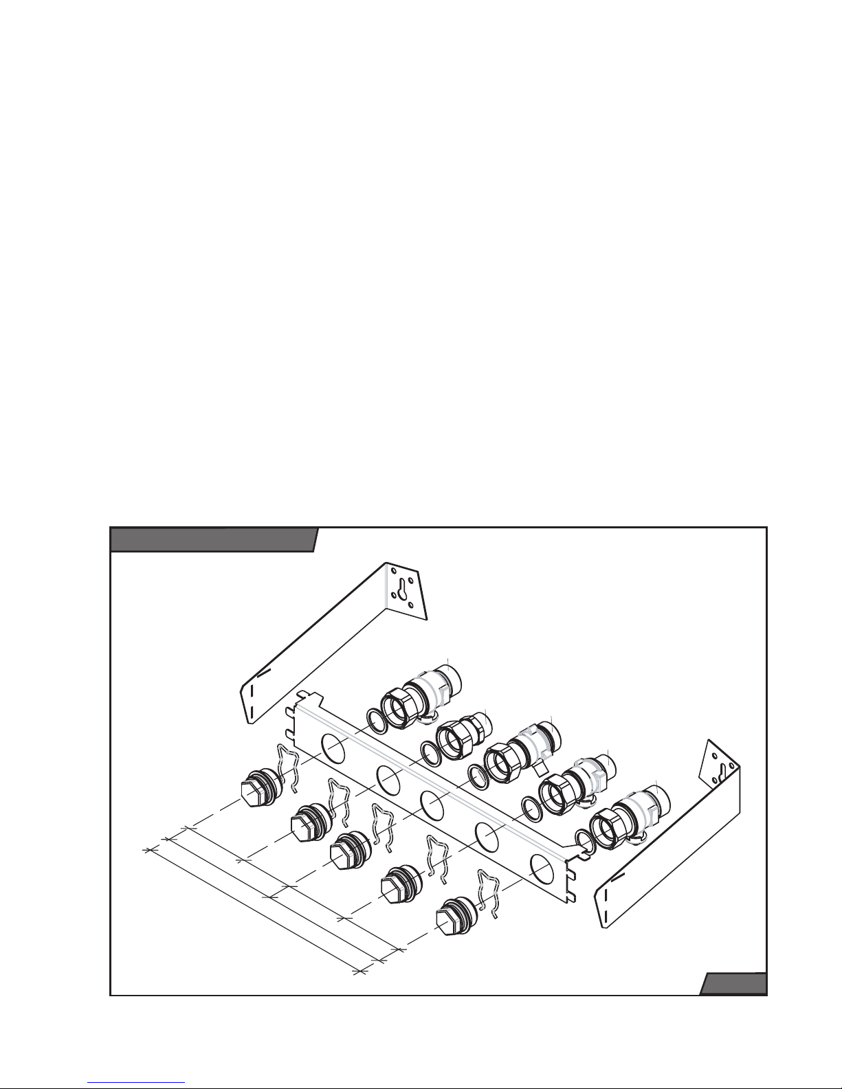
Fig. 10
64,5
129,5
116,5
246
65
51,5
65
G3/4
G3/4
G3/4
G1/2
G1/2
12. List of service centres
13. Service Book
14. NTC sensor (24KTO/KOO, 12KTO/
KOO)
15. Template
16. Combustion gas diffuser (orifi ce plate)
with internal diameter 43 mm (only for
12KTO)
Special delivery
On request the following selected accessories can be ordered:
1. Connecting ramp, Order No. 0020038446
(Fig. 10)
2. Thermolink S room control unit – twostate regulation, order no. 0020035407
3. Thermolink B room control unit – eBus
regulation, order no. 0020035406 or
Thermolink P – eBus regulation, order
no. 0020035408
4. Outdoor sensor for equithermal control,
order no. 0020040797
Connecting ramp
Page 27

25
Distribution pipes
Nominal pipe internal diameter is chosen
in the usual way, using the pump characteristic. Distribution pipes are designed
according to the requirements for the
system performance, not according to the
boiler’s maximum output. However, measures must be taken in order to ensure
suffi cient fl ow so that the water temperature difference in the supply and the
return pipe is less than or equal to 20˚C.
Minimum fl ow must be 400 l/h.
The piping system construction must prevent air bubbles from developing, making
permanent bleeding of the system easier.
Bleeding valves should be situated on all
high points of the system and on all radiators.
It is recommended to install upstream the
boiler a set of heating water, hot water and
gas isolation valves.
At the lowest point of the heating system
we recommend installation of an exhaust
valve, which shall also serve for fi lling of
the heating system.
Before fi nal installation of the boiler, the
heating distribution system pipes must be
fl ushed a few times with pressurised water.
In old, already used systems, the fl ushing
must be done in the direction opposite to
the fl owing heating water.
Important:
Before connecting the boiler
to the heating system, remove the plastic plugs located inside all connection
outlets.
Heating system cleanliness
Before installing a new boiler, it is essential to clean the system thoroughly. In old
systems it is necessary to remove all
sludge settled at the bottom of radiators
(predominantly gravity system).
In new systems it is necessary to remove
all conservation material used by majority
of radiator manufacturers.
It is recommended to install upstream
the boiler (i.e. on the heating water return
pipe) a sludge separator. The sludge
separator should be constructed in such a
way that it is easy to empty at regular time
intervals without the necessity to drain a
large quantity of water from the heating
system. The separator can be combined
with a fi lter, but a fi lter with a sieve alone
is not suffi cient protection. The fi lter and
sludge separator must be checked and
cleaned regularly.
Heating water circulation
Although the boiler is equipped with a
bypass, we recommend designing the
heating system so that the heating water
fl ows through at least some of the radiators constantly.
Note:
In the case of connection to a fl oor
heating system we recommend addition
of a safety valve against overheating to
the heating system.
Use of antifreeze compounds
We do not recommend the use of antifreeze compounds because of their
unsuitable properties for the boiler. This
concerns particularly their reduced heat
transfer, large volume expansion, ageing
and above all damage to heating water
heat exchangers.
Important:
Any defects of the boiler caused by use of antifreeze compounds will
not be covered by the boiler’s warranty.
Thermostatic radiator valves
If a room control unit is installed, at least
one of the radiators in the reference room
must be left without a thermostatic valve.
For improved temperature comfort we
recommend that all radiators in the room
containing the room control unit are left
without a thermostatic valve.
Preparing for boiler installation
Page 28

26
Hot water system
Pressure inside the hot water system must
be within the range of 1 to 6 bar. If the
pressure exceeds 6 bar, a pressure reduction valve must be fi tted on the supply
side, combined with a safety valve.
In areas with very hard water we recom-
mend to implement suitable measures to
reduce the water hardness.
Fig. 11
Mounting procedure
K
O
L
P
S
T
R
M
W
Page 29

27
Installing the boiler
Mounting the boiler on the wall
When mounting the boiler on the wall, proceed in accordance with the installation
design conditions (e.g. wall load bearing
properties, chimney inlet, pipe inlet and
outlet connections).
The mounting procedure (Fig. 11):
1. Take the paper template (M) and attach
it (for instance by adhesive tape) to the
place of installation (W). When positioning the template, user a plumb line or a
spirit level.
2. Using the marked points on the template, drill all necessary holes (mounting
bar, connecting ramp).
Please note:
If a connecting ramp (R) is
installed - not part of the boiler delivery
– the connecting end pieces of the boiler
(T) must not be used.
3. If combustion gas discharge is to be
directly via the building’s façade, project
and mark a point for a pass of the concentric ducting (O).
4. Remove paper template (M).
5. Drill the required holes, respecting the
diameters shown in the template.
6. Insert wall plugs into the holes for the
mounting bar (L) and then fasten the bar
properly with the screws provided.
7. Hang the boiler (K) on the mounting bar
(L).
8. Install the combustion gases removal
ducting (O) onto the boiler. Fill-in the
gaps between the ducting and the wall
opening with a non-fl ammable material.
9. Remove the plastic plugs from the boiler
outlets.
10. Install the sealing ring, fl ow limiter and
protective fi lter on the boiler hot water
inlet (S).
11. Install the connecting end pieces of the
boiler (T).
Note:
If connection ramp (R) is not at-
tached.
12. Install the protective fi lter to the heating
water inlet (not part of delivery).
13. Mount isolation valves on all outlets from
the boiler (not part of delivery).
14. Connect heating water, hot water and
gas distribution pipes to the isolation valves.
15. Install lever for topping up water (P) into
the heating system.
16. Run boiler (see page 10).
17. Perform check of tightness of all connections.
Mounting boiler with connecting
ramp
1. If a connection ramp is used, proceed
according to points 1 – 6 of the preceding chapter “mounting the boiler on the
wall”.
2. Assemble connecting ramp (R) according to instructions stated on the ramp
packaging.
3. Attach connecting ramp (R) to wall using
fasteners and screws.
4. Install protective fi lter (not part of delivery) to end of heating water inlet.
Note:
For reasons of easier maintenance
install a further isolation valve behind the
protective fi lter of the heating water (not
part of delivery)
5. Attach heating water, hot water and gas
distribution pipes.
6. Remove plastic plugs and securing clips
from all isolation valves and remove supporting frame of connecting ramp (R).
7. Install sealing ring, fl ow limiter and protective fi lter (S) on hot water inlet to boiler.
8. Mount boiler (K) on wall and attach it to
isolation valve.
9. Install combustion gas removal ducting
(O). Fill-in the gaps between the ducting
and the wall opening with a non-fl ammable material.
10. Install lever for topping up water (P) into
the heating system.
11. Run boiler (see page 10).
12. Perform check of tightness of all connections.
Page 30
28
Connecting the boiler to heating
water, hot water and gas distribution
pipes
The boiler pipe connection pieces must
not be subjected to any forces from the
heating water, hot water or gas piping
system. This requires precise positioning
of all connection pipes, both vertically
(height) as well as the distance from the
wall and mutual distances between inlets
and outlets.
We recommend designing the heating
system in such a way that when performing repairs, it will be possibly to drain the
boiler only.
After reconstructions, in unfavourable building dispositions etc., it is possible to connect the boiler to the heating system, the
hot water system as well as the gas mains
by means of fl exible hoses, but only those
designed for this purpose. Flexible components should be as short as possible,
must be protected against mechanical and
chemical loads and damage, and must be
replaced with new ones before the end of
their useful life or before their reliability to
meet their nominal parameters (as stated
by their manufacturers) is diminished.
Note:
The manufacturer recommends attachment of an external utility water fi lter
to the boiler inlet.
Heating system operating pressure
The heating system (measured on the
boiler) must be fi lled up to a minimum
hydraulic pressure of 1 bar (corresponds
to hydrostatic water column of 10 m).
We recommend to maintain the pressure
within the range 1.2 and 2 bar. The boiler’s
expansion vessel is suffi cient for a heating
system with not more than 110 litres of
heating water (at temperature 75°C).
Expansion vessel
Before fi lling up the heating system, check
pressure in the expansion vessel. The initial pressure inside the expansion vessel
should be 0.2 bar higher than the assumed pressure in the heating system.
If the heating system is already fi lled up,
it is necessary to shut the heating water
valves located underneath the boiler and,
using the draining valve, relieve the boiler from pressure. Then you can check the
expansion vessel pressure and if necessary increase the pressure.
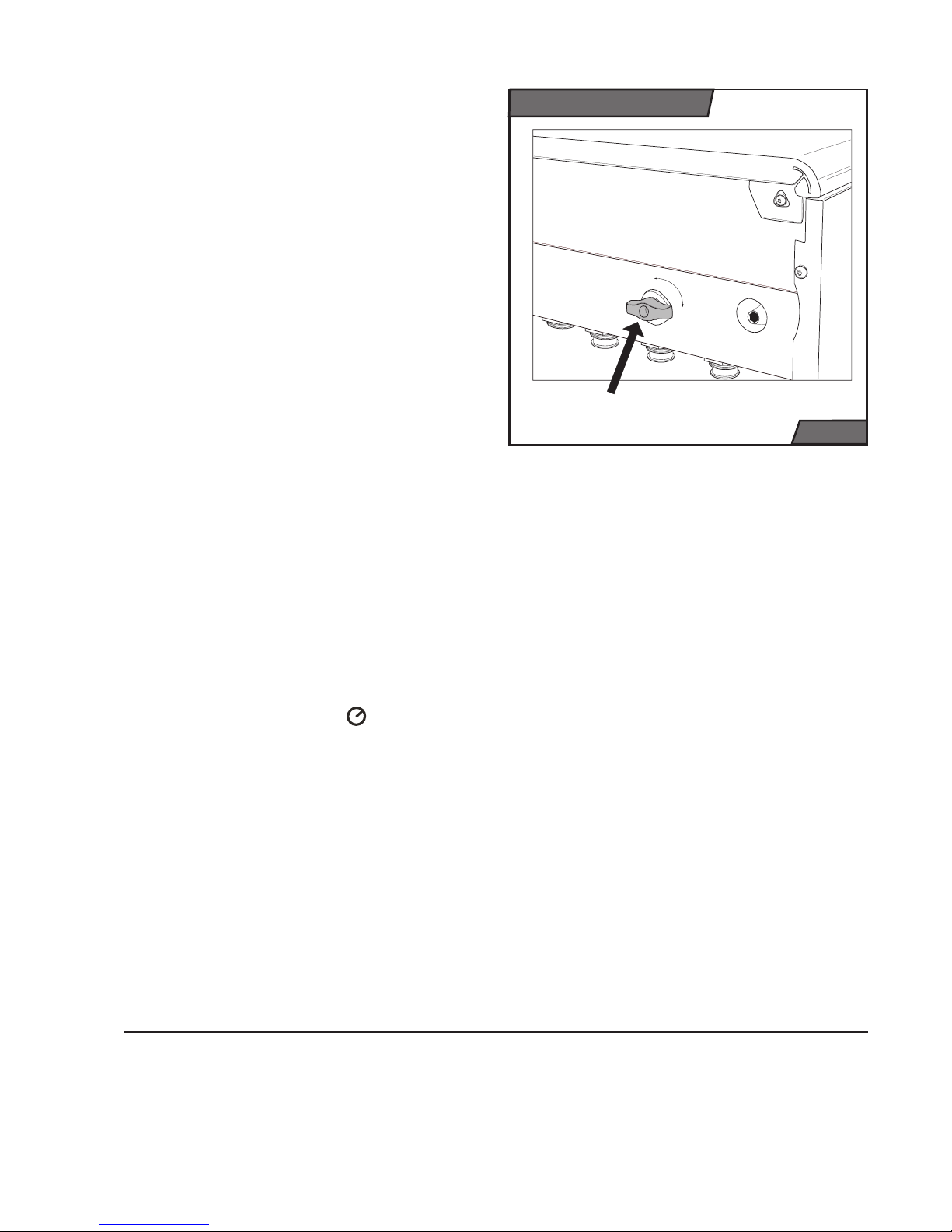
The valve for increasing pressure of the
expansion vessel is located on the right
side (Fig. 12).
Important:
Make sure that the expansion
vessel capacity is suffi cient for the volume of water in the heating system (see
installation design documentation).
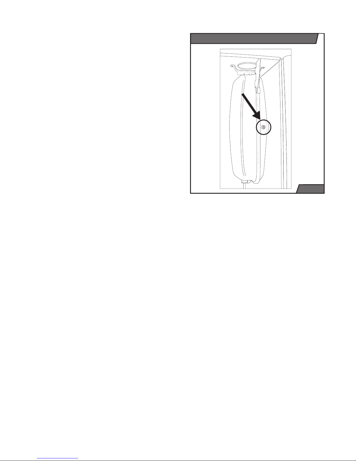
Safety valve
At the bottom of the boiler among the hydraulic group is on the right side located
a safety valve (Fig. 13). When the maximum pressure in the system is exceeded,
water or steam can be discharged from
Increasing pressure of exp. vessel
Fig. 12
Page 31
29
the safety valve, therefore we recommend
attachment of a hose to the safety valve,
discharging the water into the building’s
water waste system.
Important:
Under no circumstances may
anyone manipulate with the safety valve
while the boiler is in operation. It is also
prohibited to use the safety valve for
discharging water from the boiler or heating system. A safety valve clogged up with impurities from the heating system is
not covered by the warranty.
Connecting gas supply
The Panther version of the boiler is designed to be fuelled by natural gas with a
nominal pressure in the gas mains of 2
kPa, for which the calorifi c value is most
commonly stated as being between 9 and
10 kWh/cu.m. The indoor gas distribution pipes and the gas meter must be of
adequate size, taking into account also
the user’s other gas appliances.
All gas distribution pipes must be installed
in accordance with STN EN 1775.
Important:
We recommend sealing the
boiler’s gas connection point by tightening
the screw cap on the head of the nozzle
over the corresponding sealing (see boiler
delivery).
After completing the gas supply connection to the boiler, the air-tightness of the
implemented coupling must be thoroughly
checked.
Topping up boiler with water
Topping up water in the boiler is described
in the part “Operating instructions – Service/Maintenance”.
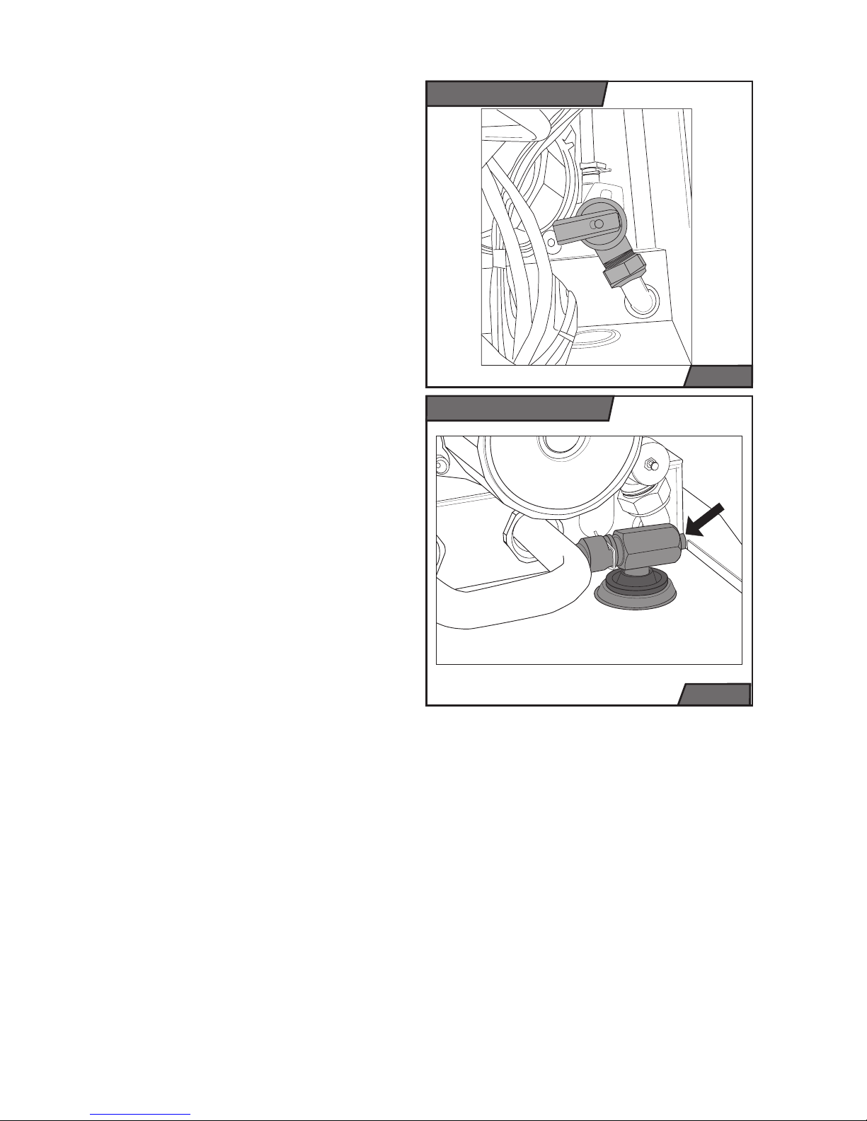
Draining water from the boiler
The draining valve’s main function is to
relieve water pressure in the boiler during
repairs. Water from the boiler can be drained using this valve only partially.
Complete draining of water either from the
boiler only or from the whole heating sys-
Fig. 13
Poistný ventil
Vypúšťací ventil
Fig. 14
tem and refi lling it again must be done through a fi ll-up (discharge) point situated in
a suitable location in the heating system.
Draining and fi lling up the heating system water and the subsequent operations
(bleeding, adjusting expansion vessel) are
not covered by the boiler’s warranty.
If there is a danger that the hot water system water inside the boiler or the distribution pipes may freeze, measures must
be implemented to prevent this from happening.
Note: The draining valve is located on the
right side of the boiler by the pump (Fig.
14).
Page 32

30
Em
Fig. 16
In the KTV and KTO models, combustion
gases must be removed and air supplied
only through a dual ducting specially designed for this purpose.
Horizontal ducting sections must have
a gradient allowing condensate to be
discharged to the outside space or to the
condensate removal fi ttings. An option to
slightly bend the joint of straight section
and elbow is used to create small deviation from square position. Vertical sections
must be always fi tted with condensate
removal fi ttings. These must be whenever
possible installed in the immediate vicinity
of the boiler’s combustion gases discharge outlet. Defects caused by condensate penetrations are not covered by the
boiler’s warranty.
Air supply/combustion gases removal
methods (according to EN 483) and
permitted ducting route lengths
Unless stated otherwise for the individual following dual ducting route design
methods and their termination outlets,
the ducting route lengths (from the boiler
connection point to the termination outlet)
may be as follows – see Table 1.
Please note:
1 Em is considered to be
either 1m of straight section or one 90˚
elbow.
Important:
When the lengths specifi ed
in Table 1 are exceeded, it is necessary
to remove the combustion gases diffuser
(aperture) from the fan outlet (Fig. 16).
The following methods of air supply and
combustion gases removal are permitted
for this boiler:
Method C12 – vhorizontal routes with
horizontal termination outlets discharging
combustion gases to free space.
When using separate ducting (80 mm) in
horizontal routes with horizontal termination outlets, the air supply inlet and the
combustion gases outlet from the same
boiler must both be situated inside a square with a side length of 0.5m.
An example of a dual horizontal ducting
route – method C
12
(according to STN EN
483) is illustrated by Fig. 16.
Method C
32
– vertical routes with vertical
termination outlets into free space. For
termination outlet of separate ducting,
the same applies as for method C12. An
example of a dual vertical ducting route
– method C32 (according to STN EN 483)
is illustrated by Fig. 17.
Method C
42
– connection to common dual
chimneys. Dual ducting from each boiler
(individual routes) may be terminated in
common chimneys; the chimney’s trans-
Fig. 15
Air supply and combustion gases removal system for KTV and KTO boilers
Combustion gases diffuser
Method C
12
Page 33

31
portation suffi ciency is assessed from
the data stated by the manufacturer of
the used chimney fl ue. If the routes are
terminated in the chimney in two mutually perpendicular directions, the minimum
vertical distance between them must be
0.45 m. If the routes are terminated in
the chimney from opposite directions, the
minimum vertical distance between them
must be 0.60 m. Outlets of routes terminated in a common dual chimney are
never fi tted with end pieces (used in routes discharging to free space)! Both route
sections (the outside – air, and the inside
– combustion gases) must safely protrude
into the chimney lumen, but not so deep
as to form an obstacle to the fl owing combustion gases or air.
In this case the concentric ducting route
must not exceed the length (elbow 90° +)
of 3 Em, the separate ducting route must
not exceed (elbow 90° +) 9 Em (as a sum
of length of the air part and the combustion gases part in total).
Method C
52
– dual ducting separated and
terminated at two different points (with different parameters, mainly pressures).
Separate ducting can also be used to
remove combustion gases and supply
combustion air (see Fig. 19). The separate
ducting routes must not be terminated at
mutually opposite building walls.
Method C
62
– connection to separately
approved and supplied piping.
Method C
82
– ducting used in cases where the air part is terminated in free space
and the combustion gases part in a common chimney.
Air may also be taken from free space
(or space with plentiful air supply) and
combustion gases discharged into a
common chimney (or again into a space
with common presence of combustion
gases). Into this method falls also the
special case detailed in the second
paragraph of section Method B
22
– see
the text below.
∅
80
∅
80
L2
L1
Em
Fig. 17
Fig. 18
Method C
32
Method C
52
Fig. 19
Method B
22
Page 34

32
Flue diameter Min. length Max. length with
aperture
Max. length
without aperture
100 / 60 1,5 Em 2 Em 6 Em
125 / 80 1,5 Em 2 Em 12 Em
80 / 80 2 + 2 Em 3 + 3 Em 17 + 17 Em
Table 1
Metoda B22 – removal of combustion
gases (including through separate tubing)
into free space and supply of combustion
air from the building’s interior in close
vicinity to the boiler (in concentric tubing
by interrupting the outside tube).
Important:
Adequate quantity of air must
be available to supply combustion air from
the building’s interior. No other appliance
may be connected to the chimney or fl ue,
and at least 1.2 cu.m or air per hour per
kW of boiler input must be available.
0
20
40
60
80
100
120
01234567
Extraction length (Em)
Pressure (Pa)
fan load characteristic
Fan load with Ø 60/100 mm extraction
Fig. 20
without diffuser with
diffuser
Extraction Length (Em)
0123456 0 2
Pressure (Pa)
105 65 57 50 45 39 34 200 34
Page 35

33
Examples of placing flue ducts
according to appendix no. 7 of SR
Government Regulation no. 92/1996
Coll.
Separate outlet on flat wall
1. Separate outlet creates a zone from the
axis of the outlet with a width a = 0.5 m,
radius b = 1.0 m and height c = 5.0 m.
Fig. 21 Diagram of formation of zone
with separate outlet of fl ue duct
2. If the axes of the outlet are at a distance
of d > 0.3 m beneath the upper part of
the window construction, the created
zone must not overlap with the surface
formed by the window. At a distance of <
0.3 m the zone bordered by the radius b
may overlap with the upper part of the
window.
Fig. 22 – Diagram of formation of zone
from axis of outlet of fl ue duct located
in vicinity of upper part of window
Dual outlet with horizontal
arrangement on flat outside wall
The distances of the dual outlet on a fl at
wall with horizontal arrangement are:
a = 1.5 m; g = 5.0 m; c = 5.0 m
In the case that g < 5 m, the zones are
penetrated, in which it is necessary to
adhere to a total zone width of 8 m, and
proportionally increase the “a” values
on both sides (e.g. g = 4.0 m then a =
2.0 m).
Fig. 23 – Dual outlet with horizontal
arrangement on fl at outside wall
Fig. 21
Fig. 22
Fig. 23
Page 36

34
Dual outlet with vertical
arrangement
The smallest distances in the case of a
dual outlet with vertical arrangement on a
fl at outside wall are:
a = 0.5 m; b = 1.0 m, c = 5.0 m, a1 depending on x as follows
x > 5.0 m is a1 = 0.5 m
x > 4.0 m is a1 = 0.6 m
x > 3.0 m is a1 = 0.75 m
x > 2.0 m is a1 = 1.0 m
x > 1.0 m is a1 = 1.2 m
Fig. 24 – Dual outlet with vertical arrangement on fl at outside wall
Important notice!
The above cases of placing flue
ducts may be used only in repairs or
reconstructions of buildings.
In other cases it is necessary to proceed
according to Government Regulation no.
410/2003 of the Ministry of Environment
of the Slovak Republic no. 706/2002 Coll.,
on sources of pollution, emission limits,
technical requirements and general conditions of operation, on recording of pollutant substances, categorisation of sources of pollution and the requirements for
ensuring diffusion of emissions of pollutant substances.
Safety measures
The distance between any fl ammable
material and the combustion gases part of
a separate ducting system must be such
that the surface temperature of this material does not exceed 80˚C.
Combustion gases outlets must not be
located in:
• places with the danger of explosion (as
defi ned by STN 33 1220)
Fig. 24
• building interiors (attics, corridors, staircases, etc.)
• places which can be closed, e.g. in gateway passages, etc.)
• underground structures (even when they
constitute no obstacle and are open),
such as tunnels, subways, etc.
It is always necessary to assess also position of a separate outlet (suction) of the air
supply as appropriate with regard to these
principles of prohibition of placement of
combustion gases outlets.
The opening through the wall for dual
ducting for air supply and fl ue removal
shall be made with adequate clearance
(approx. 120 to 150 mm) and sealed upon
completion of installation. Only incombustible material may be used for sealing (with
fl ammability grade A according to ČSN 73
0823) as e.g. plaster, gypsum etc. Penetrations through fl ammable wall or ceiling
must be made in accordance with the fi rst
paragraph of this section.
Page 37

35
The boiler is connected to power supply
by a three-core fl exible cord with a plug.
A fi xed socket through which the boiler is
connected to power mains must comply
with the provisions of STN 33 2000-4-46.
This must always have a protective (earth)
contact (pin), reliably connected by a PE
or PEN wire (yellow-and-green). The boiler
must be always connected to the protection wire (earth) through its power cord and
must be always installed in such a manner
that the socket and plug are accessible.
Use of adapters, extension cords etc., is
not permitted.
Important:
Preparation of the plug, socket
and connection of the room control unit,
which requires intervention with the boiler’s
internal wiring, must be always connected
by a qualifi ed electrician in accordance
with Public Notice No. 50/1978. Likewise servicing of the electro-technical part
must be performed by only a person with
the above qualifi cation. Before performing
any works on the electro-technical part,
the boiler must be disconnected from the
power supply by removing the power cord
plug from the power socket!
The main part of the boiler is secured by a
tube fuse (T2A / 250 V), which is located
on the control panel of the boiler – see
diagram on pages 38 - 41.
For control of the boiler using a room control room unit only a zero-potential output
room control unit may be used, i.e. a unit
which conveys no foreign voltage to the
boiler.
The load capacity of the regulator with
relay switching is 24 V/0.1 A.
The room control unit must be connected
to the boiler by a two-core cable. The
recommended copper wire cross-section
for connection of a room control unit is 1.5
sq.mm.
The room control unit connection cables
must not run concurrently with power
wires or cables.
The terminal for connection of a room
control unit with relay switching is equipped from the factory with a jumper and is
located in the electrical box of the boiler
control panel.
Room control units supporting “eBUS”
communication may be attached to Panther boilers. For this type of control we
recommend installation of only Protherm
Thermolink B or Thermolink P control
units. Only with these control units can the
manufacturer guarantee the optimum functioning of the boiler.
The room control unit conductors are attached to the boiler terminal (Fig. 25 and
26).
Using the above-mentioned room control
units it is possible to activate the function
of equithermal regulation. All the equithermal curve settings are performed with the
help of the room control unit.
Note:
To activate equithermal regulation it
is necessary to install an outside temperature sensor. The conductors of the outside
sensor are attached to the boiler terminal
(Fig. 25 and 26).
The sensor is placed on the coldest wall
of the building (most often the northern
wall).
Important:
The conductors of the room
regulator and outside sensor must not be
wired concurrently with power conductors
(wiring of 230 V AC).
Electrical connection of boiler
Page 38

36
Fig. 25
Diagram of connection of external elements – types 24(12) KTO / 24(12) KOO
KOTEL
Room control unit
Variant with
connection of external
room control unit with
relay switching.
Terminal is fitted in
factory with a jumper,
which must be
removed upon
connection of control
unit.
TANK
Power cable with plug.
Main input (230V / 50
Hz)
Variant with connection of
external room and eBUS
control unit.
Clamps for connection of
outdoor sensor.
Equithermal regulation can
be operated only if a
control unit supporting
eBUS communication is
connected.
Variant with connection of
NTC tank sensor (only
version KXO).
Variant with connection of
bimetal tank thermostat (only
version KXO)
Connection of boiler with hot water tank
The boiler can work with external types of
PROTHERM tanks (B 60 Z, B 100 MS, B
200 Z etc.). For optimal use of the boiler
and tank confi guration you must use the
NTC sensor for connection. Sensor is delivered with the boiler.
Installation of a system (boiler + tank)
always requires construction preparedness. This concerns particularly all measurements (heating water, hot water, gas).
Installation of a system may be performed
only by a professionally trained service
worker.
Page 39

37
The Panther 24 KTV, 24 KOV, 24(12) KTO
and 24(12) KOO boilers are in their basic versions designed to use natural gas
as fuel. If it is necessary to use propane
gas instead, the gas jets must be replaced and the boiler parameters set as
specifi ed. The modifi cations required to
switch to a different fuel must be carried
out by an authorised technician with a valid manufacturer’s certifi cate.
Converting to different fuel
The gas valve designated for conversion
to propane is part of the conversion kit
for switching from natural gas to propane
gas. The kit contains all necessary parts
and instructions on how to perform the
conversion.
The technical instructions for converting
to a different fuel form a separate part of
the Service Manual.
Fig. 26
KOTEL
Room control unit
Variant with
connection of external
room control unit with
relay switching.
Terminal is fitted in
factory with a jumper,
which must be
removed upon
connection of control
unit.
Power cable with plug.
Main input (230V / 50
Hz)
Variant with connection of
external room and eBUS
control unit.
Clamps for connection of
outdoor sensor.
Equithermal regulation can
be operated only if a
control unit supporting
eBUS communication is
connected.
Schéma pripojenia externých prvkov - typy 24 KTV / 24 KOV
Page 40

38
Electrical diagram of boiler PROTHERM Panther 24 KOV
Fig. 27
1 X2.24 3wv_SM_OUT_1
2 X2.12 3wv_SM_OUT_2
3 X2.23 3wv_SM_OUT_3
4 X2.11 3wv_SM_OUT_4
X90
X32
X22 X43
X51
X21
X41
X40 X91 X19 X17 X15 X10 X12
X101
X2
X20
X14
1
1
1
1
1
1
1
1 1 1 1 1 1 1
Main switch
Power cord
PE
N
N
L
L
PE
by/g br
1
2
3
4
5
7
8
9
10
6
11
12
13
14
15
16
17
18
1
1
2
2
1
1
2
2
b
b
r
bl
Room
thermostat
Tan k
sensor
X19.5
X19.2
X19.3
X19.4
b
b
g
y
1
1
2
2
1
1
2
2
Outdoor NTC
sensor
NTC tank
sensor
pump
Ignition
electrode
1
2
ZIG ignition
transformer station
GND
+Vall
4
3
GND
Testing – programming
interface
Transformer
station
TOP
sensor
b X20.8
bl X20.7
r X20.5
1
1
2
2
m b X32.1
X32.2
eBUS
1
bl
Protherm
user interface
1
1 X51.1 GND
2 X51.2 reset
4 X51.4 +5 VDC
5 X51.5 +24 VDC
6 X51.6 P-eBUS
Hot water
flow sensor
2
3
1
FUGAS
1 X2.6 GND
2 X2.10 signal
3 X2.7 +5V
1
Pressure
sensor
1 X2.20 signal
3 X2.19 +5 V
4 X2.17 GND
Reverse
sensor
Step motor
of 3-way valve
X2.9
X2.5
Hot water
sensor
X40.2
X40.1
X40.3
X40.4
Ionising
electrode
13 1
14 2
15 3
16 4
17 5
18 6
19 7
20 8
21 9
22 10
23 11
24 12
GASTEP1: G1
X2.3
X2.2
X2.4
X2.16
X2.14
X2.15
1
2
3
4
5
6
X11
1
1
Safety valve 1_2
X2.13
X2.14
Safety valve 1_1
X2.18
XT2.1
Overheat
X20.13
X20.14
Gas valve
Wire colors:
y/g - yellow/green
b - blue
br - brown
bl - black
r - red
g - green
y - yellow
Page 41

39
Electrical diagram of boiler PROTHERM Panther 24 KTV
Fig. 28
1 X2.24 3wv_SM_OUT_1
2 X2.12 3wv_SM_OUT_2
3 X2.23 3wv_SM_OUT_3
4 X2.11 3wv_SM_OUT_4
X90
X32
X22 X43
X51
X21
X41
X40 X91 X19 X17 X15 X10 X12
X101
X2
X20
X14
1
1
1
1
1
1
1
1 1 1 1 1 1 1
PE
N
N
L
L
PE
1
2
3
4
5
7
8
9
10
6
11
12
13
14
15
16
17
18
1
1
2
2
1
1
2
2
X19.5
X19.2
X19.3
X19.4
1
1
2
2
1
1
2
2
1
2
GND
+Vall
4
3
GND
1
1
2
2
m b X32.1
X32.2
eBUS
1
Protherm
user interface
1
1 X51.1 GND
2 X51.2 reset
4 X51.4 +5 VDC
5 X51.5 +24 VDC
6 X51.6 P-eBUS
2
3
1
FUGAS
1 X2.6 GND
2 X2.10 signal
3 X2.7 +5V
1
1
1 X2.20 signal
3 X2.19 +5 V
4 X2.17 GND
X2.9
X2.5
X40.2
X40.1
X40.3
X40.4
13 1
14 2
15 3
16 4
17 5
18 6
19 7
20 8
21 9
22 10
23 11
24 12
GASTEP1: G1
X2.3
X2.2
X2.4
X2.16
X2.14
X2.15
1
2
3
4
5
6
X11
1
1
Fan
X2.13
X2.14
X2.18
XT2.1
Manostat
X20.10
X20.6
Main switch
Power cord
by/g br
b
b
r
bl
Room
thermostat
Tan k
sensor
b
b
g
y
Outdoor NTC
sensor
NTC tank
sensor
pump
Ignition
electrode
ZIG ignition
transformer station
Testing – programming
interface
Transformer
station
TOP
sensor
b X20.8
bl X20.7
r X20.5
bl
Hot water
flow sensor
Pressure
sensor
Reverse
sensor
Step motor
of 3-way valve
Hot water
sensor
Ionising
electrode
Safety valve 1_2
Safety valve 1_1
Gas valve
Wire colors:
y/g - yellow/green
b - blue
br - brown
bl - black
r - red
g - green
y - yellow
Page 42
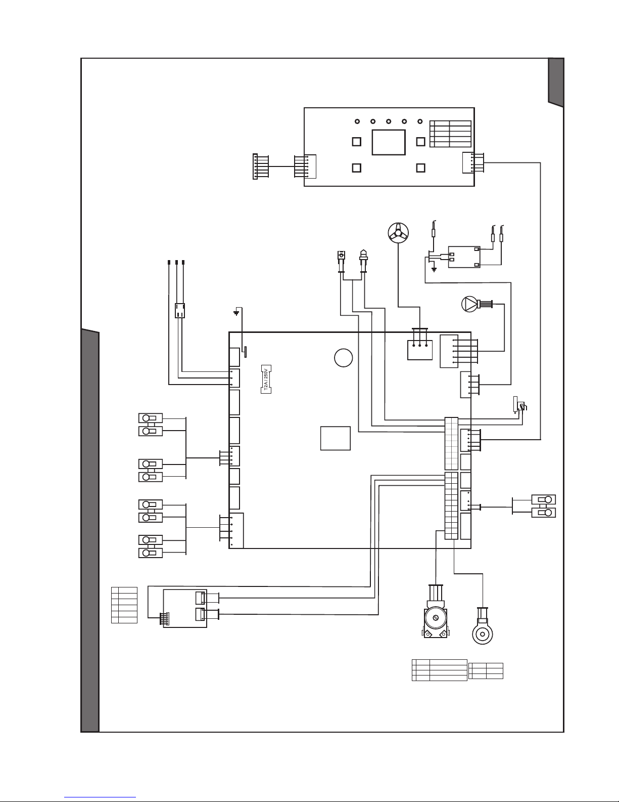
40
Electrical diagram of boiler PROTHERM Panther 24(12) KTO
Fig. 29
1 X2.24 3wv_SM_OUT_1
2 X2.12 3wv_SM_OUT_2
3 X2.23 3wv_SM_OUT_3
4 X2.11 3wv_SM_OUT_4
X90
X32
X22 X43
X51
X21
X41
X40 X91 X19 X17 X15 X10 X12
X101
X2
X20
X14
1
1
1
1
1
1
1
11 1 1 1 1 1
PE
N
N
L
L
PE
1
2
3
4
5
7
8
9
10
6
11
12
13
14
15
16
17
18
1
2
1
2
X19.5
X19.2
X19.3
X19.4
1
2
1
2
1
2
GND
+Vall
4
3
GND
1
2
mbX32.1
X32.2
eBUS
1
Protherm
user interface
1
1 X51.1 GND
2 X51.2 reset
4 X51.4 +5 VDC
5 X51.5 +24 VDC
6 X51.6 P-eBUS
1
1 X2.20 signal
3 X2.19 +5 V
4 X2.17 GND
X40.2
X40.1
X40.3
X40.4
13 1
14 2
15 3
16 4
17 5
18 6
19 7
20 8
21 9
22 10
23 11
24 12
GASTEP1: G1
X2.3
X2.2
X2.4
X2.16
X2.14
X2.15
1
2
3
4
5
6
X11
1
1
Fan
X2.13
X2.14
X2.18
XT2.1
Manostat
X20.10
X20.6
Main switch
Power cord
by/g br
b
b
r
bl
Room
thermostat
Tan k
sensor
b
b
g
y
Outdoor NTC
sensor
NTC tank
sensor
pump
Ignition
electrode
ZIG ignition
transformer station
Testing – programming
interface
Transformer
station
TOP
sensor
b X20.8
bl X20.7
r X20.5
bl
Pressure
sensor
Reverse
sensor
Step motor
of 3-way valve
Ionising
electrode
Safety valve 1_2
Safety valve 1_1
Gas valve
Wire colors:
y/g - yellow/green
b - blue
br - brown
bl - black
r - red
g - green
y - yellow
Page 43
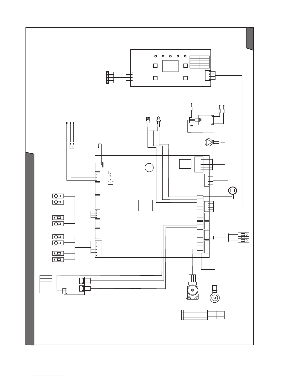
41
Electrical diagram of boiler PROTHERM Panther 24(12) KOO
Fig. 30
1 X2.24 3wv_SM_OUT_1
2 X2.12 3wv_SM_OUT_2
3 X2.23 3wv_SM_OUT_3
4 X2.11 3wv_SM_OUT_4
X90
X32
X22 X43
X51
X21
X41
X40 X91 X19 X17 X15 X10 X12
X101
X2
X20
X14
1
1
1
1
1
1
1
11 1 1 1 1 1
PE
N
N
L
L
PE
1
2
3
4
5
7
8
9
10
6
11
12
13
14
15
16
17
18
1
2
1
2
X19.5
X19.2
X19.3
X19.4
1
2
1
2
1
2
GND
+Vall
4
3
GND
1
2
mbX32.1
X32.2
eBUS
1
Protherm
user interface
1
1 X51.1 GND
2 X51.2 reset
4 X51.4 +5 VDC
5 X51.5 +24 VDC
6 X51.6 P-eBUS
1
1 X2.20 signal
3 X2.19 +5 V
4 X2.17 GND
X40.2
X40.1
X40.3
X40.4
13 1
14 2
15 3
16 4
17 5
18 6
19 7
20 8
21 9
22 10
23 11
24 12
GASTEP1: G1
X2.3
X2.2
X2.4
X2.16
X2.14
X2.15
1
2
3
4
5
6
X11
1
1
X2.13
X2.14
X2.18
XT2.1
Overheat
X20.13
X20.14
Main switch
Power cord
by/g br
b
b
r
bl
Room
thermostat
Tan k
sensor
b
b
g
y
Outdoor NTC
sensor
NTC tank
sensor
pump
Ignition
electrode
ZIG ignition
transformer station
Testing – programming
interface
Transformer
station
TOP
sensor
b X20.8
bl X20.7
r X20.5
bl
Pressure
sensor
Reverse
sensor
Step motor
of 3-way valve
Ionising
electrode
Safety valve 1_2
Safety valve 1_1
Gas valve
Wire colors:
y/g - yellow/green
b - blue
br - brown
bl - black
r - red
g - green
y - yellow
Page 44

42
Page 45

Page 46

Page 47

Page 48

Protherm spol. s r.o.
Pplk. Pľjušťa 45
909 01 Skalica
Tel.: 034 6966 101
fax: 034 6966 111
www.protherm.eu
 Loading...