

Page 1

RLX2-IHx Series
802.11a, b, g, n
Industrial Hotspots
802.11abg, RLX2-IHW
802.11abgn, Fast, RLX2-IHNF
802.11g, High Power, RLX2-IHG
802.11a, High Power, RLX2-IHA
802.11abgn, Weatherproof IP66/67, RLX2-IHNF-W/WC
Firmware version V36 and later
November 3, 2016
USER MANUAL
Page 2

Your Feedback Please
We always want you to feel that you made the right decision to use our products. If you have suggestions, comments,
compliments or complaints about our products, documentation, or support, please write or call us.
How to Contact Us
ProSoft Technology
9201 Camino Media, Suite 200
Bakersfield, CA 93311
+1 (661) 716-5100
+1 (661) 716-5101 (Fax)
www.prosoft-technology.com
support@prosoft-technology.com
Copyright © 2016 ProSoft Technology, Inc. All rights reserved.
RLX2 Series User Manual
November 3, 2016
ProSoft Technology ®, ProLinx ®, inRAx ®, ProTalk ®, and RadioLinx ® are Registered Trademarks of ProSoft Technology, Inc. All
other brand or product names are or may be trademarks of, and are used to identify products and services of, their
respective owners.
In an effort to conserve paper, ProSoft Technology no longer includes printed manuals with our product shipments. User
Manuals, Datasheets, Sample Ladder Files, and Configuration Files are provided on the enclosed DVD, and are available at
no charge from our web site: http://www.prosoft-technology.com
Content Disclaimer
This documentation is not intended as a substitute for and is not to be used for determining suitability or reliability of these
products for specific user applications. It is the duty of any such user or integrator to perform the appropriate and complete
risk analysis, evaluation and testing of the products with respect to the relevant specific application or use thereof. Neither
ProSoft Technology nor any of its affiliates or subsidiaries shall be responsible or liable for misuse of the information
contained herein. Information in this document including illustrations, specifications and dimensions may contain technical
inaccuracies or typographical errors. ProSoft Technology makes no warranty or representation as to its accuracy and
assumes no liability for and reserves the right to correct such inaccuracies or errors at any time without notice. If you have
any suggestions for improvements or amendments or have found errors in this publication, please notify us.
No part of this document may be reproduced in any form or by any means, electronic or mechanical, including
photocopying, without express written permission of ProSoft Technology. All pertinent state, regional, and local safety
regulations must be observed when installing and using this product. For reasons of safety and to help ensure compliance
with documented system data, only the manufacturer should perform repairs to components. When devices are used for
applications with technical safety requirements, the relevant instructions must be followed. Failure to use ProSoft
Technology software or approved software with our hardware products may result in injury, harm, or improper operating
results. Failure to observe this information can result in injury or equipment damage.
© 2016 ProSoft Technology, Inc. All rights reserved.
Page 3

Important Safety Information
The following Information and warnings pertaining to the radio module must be heeded:
WARNING – EXPLOSION HAZARD – DO NOT REPLACE ANTENNAS UNLESS POWER HAS BEEN SWITCHED OFF OR THE AREA
IS KNOWN TO BE NON-HAZARDOUS.
"THIS DEVICE CONTAINS ONE OF THE FOLLOWING TRANSMITTER MODULES:
FCC ID: OQ7IHG, RYK-WMIA199NI, NKRDCMA82, SWX-XR5
PLEASE SEE FCC ID LABEL ON BACK OF DEVICE."
"THIS DEVICE USES AN INTERNAL COMPACT FLASH RADIO MODULE AS THE PRIMARY RADIO COMPONENT. THE COMPACT
FLASH RADIO MODULE DOES NOT HAVE AN FCC ID LABEL. THE COMPACT FLASH RADIO MODULE HAS NO USER
SERVICEABLE PARTS."
"THIS DEVICE COMPLIES WITH PART 15 OF THE FCC RULES. OPERATION IS SUBJECT TO THE FOLLOWING TWO CONDITIONS:
(1) THIS DEVICE MAY NOT CAUSE HARMFUL INTERFERENCE, AND (2) THIS DEVICE MUST ACCEPT ANY INTERFERENCE
RECEIVED, INCLUDING INTERFERENCE THAT MAY CAUSE UNDESIRED OPERATION."
"CHANGES OR MODIFICATIONS NOT EXPRESSLY APPROVED BY THE PARTY RESPONSIBLE FOR COMPLIANCE COULD VOID
THE USER’s AUTHORITY TO OPERATE THE EQUIPMENT."
“THIS DEVICE IS CONFIGURED FOR OPERATION IN THE USA DURING MANUFACTURING. THESE CONFIGURATION CONTROLS
ARE NOT PRESENT IN THE SOFTWARE WITH WHICH THE UNIT IS SHIPPED; THEREFORE THE END USER CANNOT CHANGE THE
MAX POWER SETTINGS OR THE COUNTRY/REGION. THE MODELS SOLD & SHIPPED WITHIN THE U.S. ARE IDENTIFIED
WITHIN THE MODEL NUMBER WITH –A AS PART OF THE IDENTIFIER.”
Industry Canada Requirements:
"THIS DEVICE HAS BEEN DESIGNED TO OPERATE WITH AN ANTENNA HAVING A MAXIMUM GAIN OF 24 dB. AN ANTENNA
HAVING A HIGHER GAIN IS STRICTLY PROHIBITED PER REGULATIONS OF INDUSTRY CANADA. THE REQUIRED ANTENNA
IMPEDANCE IS 50 OHMS."
"TO REDUCE POTENTIAL RADIO INTERFERENCE TO OTHER USERS, THE ANTENNA TYPE AND ITS GAIN SHOULD BE CHOSEN
SUCH THAT THE EQUIVALENT ISOTROPICALLY RADIATED POWER (EIRP) IS NOT MORE THAN THAT REQUIRED FOR
SUCCESSFUL COMMUNICATION."
"THE INSTALLER OF THIS RADIO EQUIPMENT MUST INSURE THAT THE ANTENNA IS LOCATED OR POINTED SUCH THAT IT
DOES NOT EMIT RF FIELD IN EXCESS OF HEALTH CANADA LIMITS FOR THE GENERAL POPULATION; CONSULT SAFETY CODE 6,
OBTAINABLE FROM HEALTH CANADA."
RLX2-IHNF, RLX2-IHA, RLX2-IHG, RLX2-IHW
1. This equipment is Suitable For Use in Class I, Division2, Groups A, B, C, D or Non-Hazardous Location Only.
2. WARNING – EXPLOSION HAZARD – Substitution of Any Components May Impair Suitability for Class I, Division 2.
3. WARNING – EXPLOSION HAZARD – Do not disconnect equipment unless power has been removed or the area is
known to be non-hazardous.
4. The unit is to be connected only to PoE networks without routing to the outside plant.
5. WARNING – EXPLOSION HAZARD – The SIM Card/Personality Module connection is for initial setup and
maintenance only. Do not use, connect, or disconnect unless area is known to be non-hazardous. Connection or
disconnection in an explosive atmosphere could result in explosion.
6. Device must be powered by a Class 2 Power Source.
7. Device is an open-type and is to be installed in an enclosure suitable for the environment.
Page 4

RLX2-IHNF-W
1. The equipment shall be properly grounded with the external ground screw provided connected to building ground
as well as the antenna coaxial screen of the connector shall be grounded.
2. The common or earth side of the circuit is connected to the screen of the coaxial cable and to all accessible parts
and circuits.
3. Shall be installed in Restricted Access Location Only.
4. SUITABLE FOR USE IN CLASS I, DIVISION 2, GROUPS A, B, C AND D HAZARDOUS LOCATIONS, OR NONHAZARDOUS
LOCATIONS ONLY.
5. WARNING - EXPLOSION HAZARD - DO NOT DISCONNECT EQUIPMENT WHILE THE CIRCUIT IS LIVE OR UNLESS THE
AREA IS KNOWN TO BE FREE OF IGNITABLE CONCENTRATIONS.
6. WARNING - EXPLOSION HAZARD - SUBSTITUTION OF COMPONENT MAY IMPAIR SUITABILITY FOR CLASS I, DIVISION
2.
7. WARNING – DO NOT CONNECT OR DISCONNECT WHEN ENERGIZED.
8. Antennas are to be installed in accordance with Control Drawing 06/2514
9. Unit does not comply to the cable assy requirements of ISA 12.12.01 but does comply with the ATEX standards
IEC60079-0 & IEC60079-15. In ATEX environments, do not connect/disconnect unless area is known to be nonhazardous.
10. Unit must be wired with Phoenix Contact M12 Cable Assemblies, Model Series SAC-HZ-XX-XX-XX/XXXXX/XXXXXXXXX, that are suitable for use in Class 1, Division 2, Groups A, B, C, and D Hazardous Locations.
RLX2-IHNF-WC
1. The equipment shall be properly grounded with the external ground screw provided connected to building ground
as well as the antenna coaxial screen of the connector shall be grounded.
2. The common or earth side of the circuit is connected to the screen of the coaxial cable and to all accessible parts
and circuits.
3. Shall be installed in Restricted Access Location Only.
4. SUITABLE FOR USE IN CLASS I, DIVISION 2, GROUPS A, B, C AND D HAZARDOUS LOCATIONS, OR NONHAZARDOUS
LOCATIONS ONLY.
5. WARNING - EXPLOSION HAZARD - DO NOT DISCONNECT EQUIPMENT WHILE THE CIRCUIT IS LIVE OR UNLESS THE
AREA IS KNOWN TO BE FREE OF IGNITABLE CONCENTRATIONS.
6. WARNING - EXPLOSION HAZARD - SUBSTITUTION OF COMPONENT MAY IMPAIR SUITABILITY FOR CLASS I, DIVISION
2.
7. WARNING – DO NOT CONNECT OR DISCONNECT WHEN ENERGIZED
8. Antennas are to be installed in accordance with Control Drawing 06/2514
Page 5

RLX2-IHNF-TW
低功率射頻警語:
DGT Warning Statement
第十二條
經型式認證合格之低功率射頻電機,非經許可,公司、
商號或使用者均不得擅自變更頻率、加大功率或變更原
設計之特性及功能。
Article 12
Without permission, any company, firm or user shall not alter the frequency, increase the power, or change the
characteristics and functions of the original design of the certified lower power frequency electric machinery.
第十四條
低功率射頻電機之使用不得影響飛航安全及干擾合法
通信;經發現有干擾現象時,應改善至無干擾時方得
繼續使用。前項合法通信,指依電信法規定作業之無
線電通信。低功率射頻電機須忍受合法通信或工業、
科學及醫療用電波輻射性電機設備之干擾。
Article 14
The application of low power frequency electric machineries shall not affect the navigation safety nor interfere a legal
communication, if an interference is found, the service will be suspended until improvement is made and the interference
no longer exists.
Page 6

ProSoft Part Number
Max Gain and Type
A2403NBH-OC
3 dBi Omni N-BH jack whip less 2.4GHz
A2404NBHW-OC
4 dBi Omni N BH jack low profile 2.4GHz
A2404NJ-OC
4 dBi Omni N jack collinear with mounting hardware 2.4GHz
A2405S-OA
5 dBi Omni RP-SMA articulating 2.4GHz
A2405S-OS
5 dBi Omni RP-SMA straight 2.4GHz
A2406NJ-OC
6 dBi Omni N jack collinear with mounting hardware 2.4GHz
A2406NJ-OCD
6 dBi Omni N jack heavy duty collinear with mounting hardware 2.4GHz
A2406S3-DP
6 dBi Panel RP-SMA MIMO antenna with 3 foot pigtail 2.4GHz
A2408NJ-DP
8 dBi Directional patch panel N jack with mounting hardware 2.4GHz
A2408NJ-OC
8 dBi Omni N jack collinear with mounting hardware 2.4GHz
A2409NJ-OCD
9 dBi Omni N jack heavy duty collinear with mounting hardware 2.4GHz
A2410NJ-DY
10 dBi Directional N jack Yagi with mounting hardware 2.4GHz
A2410NJ-OCM
10 dBi Omni N jack collinear for marine environment, 2.4GHz
A2412NJ3-DP
12 dBi Panel N-Jack MIMO antenna 2.4GHz
A2413NJ-DP
13 dBi Directional patch panel N jack with mounting hardware 2.4GHz
A2415NJ-DY
15 dBi Directional N jack Yagi with mounting hardware 2.4GHz
A2416NJ-DS
16 dBi Directional 120 degree sector N jack with mounting hardware 2.4GHz
A2419NJ-DB
19 dBi Directional N jack parabolic with mounting hardware 2.4GHz
A2419NJ-DP
19 dBi patch panel N jack with mounting hardware 2.4GHz
A2424NJ-DB
24 dBi Directional N jack parabolic with mounting hardware 2.4GHz
A2502S-OA
2 dBi Omni RP-SMA articulating 2.4/5GHz
A2506NJ-OC
6/8 dBi Omni N jack collinear with mounting hardware 2.4/5GHz
A5003S-OBH
3 dBi Omni RP-SMA bulkhead mount with 5' LMR195 pigtail 5GHz
A5006NJ-OC
6 dBi Omni N jack collinear with mounting hardware 5GHz
A5007S3-DP
7 dBi Panel RP-SMA MIMO antenna with 3 foot pigtail 5GHz
A5009NJ-OC
9 dBi Omni N jack collinear with mounting hardware 5GHz
A5017NJ3-DP
17 dBi Panel N-Jack MIMO antenna 5GHz
A5019NJ-DP
19 dBi directional N jack panel with mounting hardware 5GHz
A5024NJ-DP
24 dBi directional N jack panel with mounting hardware 5GHz
A5812NJ-OC
12 dBi Omni N jack collinear with mounting hardware 5.8GHz
A5829NJ-DB
29 dBi directional N jack parabolic with mounting hardware 5.8GHz
A2503S3-O
3/4 dBi Omni RP-SMA MIMO antenna with 3 foot pigtail 2.4/5GHz
A2503S6-O
3/4 dBi Omni RP-SMA Dual MIMO antenna with 3 foot pigtail 2.4/5GHz
A2506NJ3-O
6 dBi Omni N-Jack Single MIMO antenna with 3 foot pigtail 2.4/5GHz
Recommended Antennas
ProSoft offers a variety of Antennas and Cables for use with your RadioLinx device. The following is a sample of available
antennas. For a complete list and description, please visit our website: http://www.prosoft-
technology.com/Products/Industrial-Wireless - Antennas and Accessories.
An adapter may be needed for some of the listed antennas to operate with certain radios.
Antenna Spacing Requirements for User Safety
It is important to keep the radio's antenna a safe distance from the user. To meet the requirements of FCC part 2.1091 for
radio frequency radiation exposure, this radio must be used in such a way as to guarantee at least 20 cm between the
antenna and users. Greater distances are required for high-gain antennas. The FCC requires a minimum distance of 1 mW
*cm2 power density from the user (or 20 cm, whichever is greater).
If a specific application requires proximity of less than 20 cm, the application must be approved through the FCC for compliance to part
2.1093.
Page 7

Page 8

Contents
YOUR FEEDBACK PLEASE ............................................................................................................................................ 2
HOW TO CONTACT US ............................................................................................................................................... 2
CONTENT DISCLAIMER ............................................................................................................................................... 2
IMPORTANT SAFETY INFORMATION .............................................................................................................................. 3
Industry Canada Requirements: ...................................................................................................................... 3
RLX2-IHNF, RLX2-IHA, RLX2-IHG, RLX2-IHW .................................................................................................... 3
RLX2-IHNF-W ................................................................................................................................................... 4
RLX2-IHNF-WC ................................................................................................................................................. 4
RLX2-IHNF-TW ................................................................................................................................................. 5
Recommended Antennas ................................................................................................................................. 6
Antenna Spacing Requirements for User Safety .......................................................................................................... 6
START HERE .................................................................................................................................................... 13
ABOUT THIS MANUAL ............................................................................................................................................. 13
ABOUT THE RLX2 INDUSTRIAL HOTSPOT™ PRODUCTS ................................................................................................... 14
General Features ........................................................................................................................................... 14
PACKAGE CONTENTS ............................................................................................................................................... 17
RLX2-IHA, -IHG, -IHNF, -IHW .......................................................................................................................... 17
RLX2-IHNF-W ................................................................................................................................................. 17
RLX2-IHNF-W Cables (sold separately) ....................................................................................................................... 17
RLX2-IHNF-WC ............................................................................................................................................... 18
Industrial Hotspot Bench Test Kit (RLX-IHBTK) .............................................................................................. 18
Personality Module ........................................................................................................................................ 18
INDUSTRIAL HOTSPOT BROWSER CONFIGURATION TOOL .............................................................................. 19
SYSTEM REQUIREMENTS ........................................................................................................................................... 19
INSTALLATION FROM DVD ........................................................................................................................................ 20
INSTALLATION FROM THE PROSOFT WEBSITE ............................................................................................................... 22
RLX2 QUICK SETUP ................................................................................................................................................ 23
Master Radio Configuration .......................................................................................................................... 24
Repeater Radio Configuration ....................................................................................................................... 35
Client Radio Configuration ............................................................................................................................. 36
INSTALLING A REPLACEMENT RADIO USING A PERSONALITY MODULE ............................................................................... 41
PLANNING THE NETWORK ......................................................................................................................................... 41
Installation Questions .................................................................................................................................... 43
Planning the Physical Installation .................................................................................................................. 43
PROSOFT WIRELESS DESIGNER .................................................................................................................................. 44
Functional Specifications: .............................................................................................................................. 46
Personality Module Configuration Restoration ............................................................................................. 47
INSTALLING THE RADIOS................................................................................................................................. 49
CONNECTING ANTENNAS .......................................................................................................................................... 51
TEST THE NETWORK INSTALLATION PLAN ..................................................................................................................... 51
DIAGNOSTICS AND TROUBLESHOOTING ......................................................................................................... 53
Page 9

DIAGNOSTICS ........................................................................................................................................................ 54
Checking the Ethernet Cable ......................................................................................................................... 54
LED Display .................................................................................................................................................... 55
RETRIEVING THE DEFAULT PASSWORD ........................................................................................................................ 56
RLX2-IHNF-W and RLX2-IHNF-WC Reset ....................................................................................................... 56
Resetting All Other Radios ............................................................................................................................ 57
TROUBLESHOOTING IH BROWSER ERROR MESSAGES ..................................................................................................... 57
TROUBLESHOOTING MISSING RADIOS ........................................................................................................................ 58
IMPROVING SIGNAL QUALITY .................................................................................................................................... 58
DETAILED RADIO CONFIGURATION / DIAGNOSTICS ........................................................................................ 59
OPENING THE RADIO CONFIGURATION / DIAGNOSTIC UTILITY ......................................................................................... 59
Read-Only Fields............................................................................................................................................ 60
Configuration Help ........................................................................................................................................ 60
Radio Status .................................................................................................................................................. 63
Address Table ................................................................................................................................................ 67
Port Status .................................................................................................................................................... 68
Basic Settings ................................................................................................................................................ 71
Basic Wireless Settings ............................................................................................................................................... 72
Wireless Security Settings .......................................................................................................................................... 75
Advanced Settings ......................................................................................................................................... 84
Advanced Wireless Settings ....................................................................................................................................... 85
Roam Control ............................................................................................................................................................. 89
Parent Link Settings ...................................................................................................................................... 93
Advanced Network Settings .......................................................................................................................... 96
Serial Settings.............................................................................................................................................. 101
Serial Encapsulation Mode ....................................................................................................................................... 101
QoS Settings ................................................................................................................................................ 105
VLAN Settings .............................................................................................................................................. 107
APPLY CHANGES .................................................................................................................................................. 109
CANCEL CHANGES ................................................................................................................................................ 109
FACTORY DEFAULTS .............................................................................................................................................. 109
RLX2-IHNF DFS SUPPORT .................................................................................................................................... 110
DFS Radio Operations ................................................................................................................................. 110
DFS Auto Select ........................................................................................................................................... 111
RADIOLINX INDUSTRIAL HOTSPOT BROWSER DETAILS ................................................................................. 113
PRIMARY RADIO FUNCTIONS .................................................................................................................................. 114
FILE MENU ......................................................................................................................................................... 115
Scan Setup ................................................................................................................................................... 115
Scan ............................................................................................................................................................. 116
Clear ............................................................................................................................................................ 116
Import ......................................................................................................................................................... 116
Export .......................................................................................................................................................... 116
Freeze .......................................................................................................................................................... 116
Print............................................................................................................................................................. 116
Print Preview ............................................................................................................................................... 117
Page 10

Print Setup ................................................................................................................................................... 117
Exit ............................................................................................................................................................... 117
OPERATIONS MENU .............................................................................................................................................. 118
Connect ........................................................................................................................................................ 118
Assign IP....................................................................................................................................................... 119
Update Firmware ......................................................................................................................................... 120
Ping Device .................................................................................................................................................. 121
DIALOGS MENU ................................................................................................................................................... 122
Wireless Clients ............................................................................................................................................ 122
Ethernet Nodes ............................................................................................................................................ 123
Scan List ....................................................................................................................................................... 123
802.11 Access Point Detector ................................................................................................................................... 124
Port Table .................................................................................................................................................... 124
All 4 Dialogs ................................................................................................................................................. 124
Close All ....................................................................................................................................................... 124
Event Log ..................................................................................................................................................... 125
Properties .................................................................................................................................................... 126
VIEW MENU ........................................................................................................................................................ 127
Toolbar ........................................................................................................................................................ 127
Status Bar .................................................................................................................................................... 127
List View ....................................................................................................................................................... 128
Topology View ............................................................................................................................................. 132
Zoom In ........................................................................................................................................................ 133
Zoom Out ..................................................................................................................................................... 133
Zoom to Fit ................................................................................................................................................... 133
Show Ping Stations ...................................................................................................................................... 134
Show Parents - All ........................................................................................................................................ 135
Show Parents - One ..................................................................................................................................... 136
Print Area ..................................................................................................................................................... 136
Reset Columns ............................................................................................................................................. 137
Select Columns ............................................................................................................................................. 137
HELP MENU ........................................................................................................................................................ 138
Help Topics................................................................................................................................................... 138
About RLX IH Browser .................................................................................................................................. 139
RLX2 VIRTUAL LAN (VLAN) FUNCTIONALITY.................................................................................................. 141
TRANSPARENT SUPPORT OF VLAN TAGS (802.1Q) .................................................................................................... 141
PORT/RADIO-BASED VLAN TAGGING WITH MANAGED SWITCHES ................................................................................. 142
PORT/RADIO-BASED VLAN TAGGING WITHOUT MANAGED SWITCHES............................................................................ 143
ETHERNET/IP™ AND MODBUS TCP/IP SUPPORT ....................................................................................................... 144
MODBUS TCP/IP SERVER SUPPORT ......................................................................................................................... 144
ETHERNET/IP™ SERVER SUPPORT ........................................................................................................................... 145
REFERENCE ................................................................................................................................................... 147
PRODUCT OVERVIEW ............................................................................................................................................. 147
COMPATIBILITY WITH PROSOFT RLXIB SERIES RADIOS ................................................................................................. 149
Page 11

MASTER CHANNEL-FREQUENCY TABLE ..................................................................................................................... 151
FCC EMISSION REGULATIONS ................................................................................................................................. 152
2.4 GHz Band, Point-To-Multipoint ............................................................................................................. 152
2.4 GHz Band, Point-To-Point ...................................................................................................................... 152
5 GHz Bands, Point-To-Multipoint .............................................................................................................. 153
5 GHz Bands, Point-To-Point ....................................................................................................................... 153
RADIO HARDWARE ............................................................................................................................................... 154
Radio Power Requirements (RLX2-IHNF-W) ................................................................................................ 154
Ethernet Cable Specifications ...................................................................................................................... 157
Ethernet Cable Configuration (RLX2-IHNF-W) ............................................................................................. 158
Ethernet Cable Configuration (all other radios) .......................................................................................... 159
RLX2-IHA DETAILED SPECIFICATIONS ...................................................................................................................... 160
RLX2-IHG DETAILED SPECIFICATIONS ...................................................................................................................... 161
RLX2-IHNF, -W, -WC DETAILED SPECIFICATIONS ..................................................................................................... 162
RLX2-IHW DETAILED SPECIFICATIONS ..................................................................................................................... 164
ANTENNA CONFIGURATION.......................................................................................................................... 167
ANTENNAS .......................................................................................................................................................... 167
Control Drawing .......................................................................................................................................... 168
Antenna Pattern .......................................................................................................................................... 169
Antenna Gain .............................................................................................................................................. 170
Antenna Polarity ......................................................................................................................................... 170
Whip Antennas ............................................................................................................................................ 171
Collinear Array Antennas ............................................................................................................................ 171
Yagi Array Antenna ..................................................................................................................................... 172
Parabolic Reflector Antennas ...................................................................................................................... 173
RLX2 Approved Antennas ............................................................................................................................ 173
Antenna Location, Spacing, and Mounting ................................................................................................. 175
RSLOGIX5000™ AOI SUPPORT ....................................................................................................................... 177
IMPORTING THE AOI ............................................................................................................................................. 177
Setting up Communication Parameters ...................................................................................................... 177
Installing the AOI......................................................................................................................................... 181
SUPPORT, SERVICE & WARRANTY ................................................................................................................. 189
CONTACTING TECHNICAL SUPPORT .......................................................................................................................... 189
WARRANTY INFORMATION ..................................................................................................................................... 190
GLOSSARY OF TERMS .................................................................................................................................... 191
INDEX ........................................................................................................................................................... 205
Page 12

Page 13

RLX2 Industrial Hotspot Series
Model
Standards
Maximum Output Power
RLX2-IHA
IEEE 802.11a
24 dBm (250 mW)
RLX2-IHG
IEEE 802.11b/g
24 dBm (250 mW)
RLX2-IHNF
IEEE 802.11a/b/g/n
17 dBm (50 mW)
RLX2-IHNF-W
IEEE 802.11a/b/g/n
17 dBm (50 mW)
RLX2-IHNF-WC
IEEE 802.11a/b/g/n
17 dBm (50mW)
RLX2-IHW
IEEE 802.11a/b/g
20 dBm (200 mW)
S T A R T H E R E
For most applications, the installation and configuration steps described in the following
topics will work without additional programming. ProSoft Technology strongly
recommends the completion of the steps in this chapter before developing a custom
application.
About This Manual
This manual covers the entire RadioLinx® RLX2 Industrial Hotspot™ series of radio
products. There are six products available in this product line:
Beside the different operating frequencies and output power levels, these radios all
operate in a similar fashion. Different models operating on common frequencies can
communicate with each other. Furthermore, RLX2 series radios can communicate with
ProSoft Technology’s legacy RLXIB series of radios (except RLXIB-IHN). Details on the
specific differences between the RLX2 and RLXIB series products can be found in the
Compatibility with ProSoft RLXIB Series Radios section on page 149.
ProSoft Technology, Inc. Page 13 of 208
November 3, 2016
Page 14

RLX2 Industrial Hotspot Series
Power
While booting up
When fully operational
RF Transmit
While transmitting over wireless
RF Receive
While receiving over wireless
Serial
When a serial cable is attached
Ethernet
When Ethernet data is being transferred
Net
Alternates red and green if SD card
with new configuration inserted
Mod
Alternates red and green if SD card
with new configuration inserted
Signal Strength LEDs: SD card inserted
Alternates green and amber if SD card
with new configuration inserted
Signal Strength LEDs: running in Client or
Repeater Modes
No Signal
Radio linked, Poor Signal
Radio linked, Fair Signal
Signal Strength LEDs: running in Master Mode
No radios linked
One or more radios linked (right
LED blinking).
DFS Channel Availability Check in
progress (all LEDs blinking Amber)
About the RLX2 Industrial Hotspot™ Products
General Features
The RadioLinx® 802.11 Industrial Hotspots™ are high-speed wireless Ethernet radios with
Power over Ethernet (PoE) and Serial Encapsulation. All radios operate at speeds up to
54 Mbps, and the RLX2-IHNF operates at speeds up to 300 Mbps. Designed for industrial
installations, the RLX2 series offers many features including hazardous location
certifications, Bridging, IGMP Snooping, OFDM for noise immunity, repeater mode to
extend range, QoS, VLANs, RADIUS Server support, automatic parent selection for selfhealing, OPC server diagnostics, extended temperature, high vibration/shock and DINrail mounting.
LED Indicators
The LED indicators on the front panel indicate the status of the radio while booting up
and during operation. The LED states are summarized below.
Page 14 of 208 ProSoft Technology, Inc.
November 3, 2016
Page 15

RLX2 Industrial Hotspot Series
Antenna Ports
Each RLX2 series radio has active antenna connectors on the top as shown below:
RLX2-IHA, RLX2-IHG
These radios have a single active antenna port:
RLX2-IHNF
This radio has three active antenna ports allowing MIMO operation:
RLX2-IHNF-W
This weatherproof, hazardous location radio is Class I, DIV 2 compliant and has three
active antenna ports for MIMO operation.
ProSoft Technology, Inc. Page 15 of 208
November 3, 2016
Page 16

RLX2 Industrial Hotspot Series
RLX2-IHNF-WC
This weatherproof, hazardous location radio is a conduit version and is Class I, DIV 2
compliant. It has three active antenna ports for MIMO operation.
RLX2-IHW
This radio uses the right-side antenna port for transmit and receive. An optional
antenna can be attached to the left-side antenna port for receive diversity to
improve performance in some applications.
Page 16 of 208 ProSoft Technology, Inc.
November 3, 2016
Page 17

RLX2 Industrial Hotspot Series
Qty.
Part Name
Part Number
Part Description
1
RLX2 Series Radio
Varies
RadioLinx® RLX2 802.11 Industrial Hotspot
1
Personality Module
001-005700
Industrial Grade MicroSD card (blank, in plastic
bag)
1
Power Connector
002-0116
Mating power connector for the RLX2 radios,
for attachment to customer’s power supply.
1
Power Connector Wiring
Tool
357-0061
Tool to assist wiring the power connector.
1
Antenna
A2502S-OA
2 dBi Omni RP-SMA articulating, 2.4/5GHz. This
antenna is suitable for all RLX2 radio products.
Qty.
Part Name
Part Number
Part Description
1
RLX2 Series Radio
RLX2-IHNF-W
RadioLinx® RLX2 802.11 Industrial Hotspot
Weatherproof
1
ProSoft Solutions DVD
DVD-001
Contains sample programs, utilities, firmware
images, and documentation.
2
U-mounting brackets
Pole mounting brackets
1
IP67 M12 Cap
Water tight cap
Part Name
Part Number
Part Description
Locking Clip
CUL-M12-LOCKCLIP
7 foot (2m), M12 to RJ45, Network Cable/
PoE
or
33 foot (10m), M12 to RJ45, Network
Cable/PoE
CULRJ45-M12-007
CULRJ45-M12-033
7 foot Network PoE cable
33 foot Network PoE cable
33 foot (10m), M12 to unterminated leads,
Power Cable
or
10 foot (3m), M12 to unterminated leads,
Power Cable
CULPWR-M12-033
CUPLWR-M12-010
33 foot Power Cable
10 foot Power Cable
Package Contents
RLX2-IHA, -IHG, -IHNF, -IHW
The following components are included with standard RLX2 radio products:
RLX2-IHNF-W
The following components are included with Weatherproof RLX2 radio products:
RLX2-IHNF-W Cables (sold separately)
The following cables are for outdoor locations:
ProSoft Technology, Inc. Page 17 of 208
November 3, 2016
Page 18

RLX2 Industrial Hotspot Series
Qty.
Part Name
Part Number
Part Description
1
RLX2 Series Radio
RLX2-IHNF-WC
RadioLinx® RLX2 802.11 Industrial Hotspot
1
5 foot CAT 6 Ethernet
PoE cable
Preinstalled 6 foot CAT 6 Ethernet PoE cable
1
5 foot flying leads power
cable
Preinstalled 6 foot flying leads power cable
2
U bolts for mounting
Pole mounting brackets
1
Oval Clip & Seal Cap
Oval clip and seal cap for conduit connections
1
ProSoft Solutions DVD
DVD-001
Contains sample programs, utilities, firmware
images, and documentation.
Qty.
Part Name
Part Number
Part Description
1
Power Supply
RL-PS007-2
AC Power Adapter, 12V1.6A w/2 pin & 4 plug
Set
1
Cable
RL-CBL025
5 foot Ethernet Straight-Thru Cable
1
Cable
085-1007
6 foot RS232 serial cable
1
Adapter
HRDNULL-DB9
RS232 null modem serial adapter
RLX2-IHNF-WC
The following components are included with Weatherproof Hazardous Location RLX2
radio products:
Industrial Hotspot Bench Test Kit (RLX-IHBTK)
The standard radio products are intended for deployment into production systems and
do not include accessory power supplies or cables. For bench testing of radios, an
optional bench test kit provides these accessories:
Personality Module
The RLX2 series of industrial hotspots include a feature for quickly moving the
configuration from an installed radio to a replacement using a provided MicroSD card.
This feature reduces the time to replacement of a damaged radio. Consideration of how
to use this feature in advance of installation is necessary to take advantage of this
feature.
Note: The RLX2-IHNF-W and -WC do not have a Personality Module.
Important: Before installing, please verify all listed product items are present. If any of these
components are missing, please contact ProSoft Technology Support for replacements.
Page 18 of 208 ProSoft Technology, Inc.
November 3, 2016
Page 19

RLX2 Industrial Hotspot Series
I N D U S T R I A L H O T S P O T B R O W S E R
C O N F I G U R A T I O N T O O L
The Industrial Hotspot Browser Configuration Tool (hereafter called the IH Browser) is
used for setup and configuration of the RLX2 radios. It is designed for personal
computers running Microsoft Windows operating systems. The IH Browser can be
installed from the product DVD shipped with the RLX2 radio product, or it can be
downloaded from the ProSoft website.
System Requirements
The RLX2-IHx browser is designed for Microsoft Windows.
Supported Operating systems:
Microsoft Windows XP professional 32-bit with Service Pack 3
Microsoft Windows 7 Professional 32- or 64-bit, with Service Pack 1
Microsoft Windows 8 Release Preview 32- or 64-bit
Other Microsoft Windows operating system versions may work but have not been
tested by ProSoft and are not officially supported.
Minimum hardware requirements are:
Pentium
128 Mbytes of RAM minimum, 256 Mbytes or more of RAM recommended
100 MB available hard drive space
256-color VGA graphics adapter, 800 x 600 minimum resolution (True Color 1024 x
768 resolution or better recommended)
At least one 100BASET or 1000BASET network interface. A second interface is often
useful to setup a small private network for initial configuration and testing.
In addition, these items may be needed:
A DVD-ROM drive, if installing the RadioLinx IH Browser from optical media.
An RS-232 port on the PC or a USB-to-serial convertor cable, to use serial
encapsulation features or to access system debugging information.
An internet connection may be useful to download updated product information
from the ProSoft Technology website at http://www.prosoft-technology.com
®
II 450 MHz minimum. Pentium III 733 MHz (or better) recommended
ProSoft Technology, Inc. Page 19 of 208
November 3, 2016
Page 20

RLX2 Industrial Hotspot Series
Installation from DVD
1. Insert the ProSoft Solutions DVD in the DVD drive. On most computers, a menu
screen will open automatically. If a menu does not appear within a few seconds,
follow these steps:
2. Click the Start button, and then choose Run.
3. In the Run dialog box, click the Browse button.
4. In the Browse dialog box, click My Computer. In the list of drives, choose the
DVD drive where the ProSoft Solutions DVD was inserted.
5. Open the DVD and double-click the ProSoft_DVD.exe file to run it.
6. The DVD should display a startup screen like this:
7. Type the product name into the search box and click Search. Here is an example
of searching for the RLX2-IHNF:
Page 20 of 208 ProSoft Technology, Inc.
November 3, 2016
Page 21

RLX2 Industrial Hotspot Series
8. Click on the Product Name. The screen displays the contents for this module.
9. Double-click on RadioLinx IH Browser v3.136 (or a newer version if available) to
launch the installation wizard.
10. Follow the instructions on the installation wizard to install the program with its
default location and settings.
11. When the installation is complete, a prompt to restart the computer may
appear if certain files were in use during installation. The updated files will be
installed during the restart process.
ProSoft Technology, Inc. Page 21 of 208
November 3, 2016
Page 22

RLX2 Industrial Hotspot Series
Installation from the ProSoft Website
If the RadioLinx IH Browser was downloaded from the ProSoft website, it will be
packaged as a compressed zip file. Double–click the zip file after downloading. The
Windows extraction wizard will extract the installation file (RadioLinx IH Browser
3.130.msi or a newer version). Then double-click the .msi file to install the IH Browser.
Page 22 of 208 ProSoft Technology, Inc.
November 3, 2016
Page 23

RLX2 Industrial Hotspot Series
RLX2 Quick Setup
This section describes how to setup RLX2 radios in a minimal configuration before
deploying them in the permanent installation. It will help verify the radios are
operational along with getting familiar with basic configuration procedures.
Note that the procedures described in this section assume the radios are in their default
configurations as shipped by ProSoft. If that is not the case, reset the radios to factory
defaults before attempting these procedures.
In any given network, there must be at least one RLX2 radio acting as a Master. Other
radios configured as Repeaters or Clients will connect wirelessly to the Master to form a
network bridge between their Ethernet interfaces.
Because most wireless networks consist of one Master radio and multiple Repeaters, all
RLX2 radios are shipped from ProSoft pre-configured as Repeaters. Hence our first task
is to configure one radio as the network Master.
IMPORTANT: If a ProSoft Power adapter RL-PS007-2 (supplied with the RLX-IHBTK Bench Test
Kit) is not present, see instructions on wiring the power connector in this manual.
ProSoft Technology, Inc. Page 23 of 208
November 3, 2016
Page 24

RLX2 Industrial Hotspot Series
Master Radio Configuration
The first step is to select the radio to use as a Master. All RLX2 radios in a network are
typically the same model, although this is not necessary.
IMPORTANT: The only RLX2 radios that do not have any channels in common with each other are
the RLX2-IHA and RLX2-IHG. The RLX2-IHW and RLX2-IHNF radios can communicate with each
other and with the RLX2-IHA and RLX2-IHG radios.
If all the radios are present on the workbench, antennas may not be needed for this
configuration exercise. Radios without antennas may have sufficient signal strength to
link over short distances, without radiating or receiving unnecessary RF energy in the
surrounding environment. However, connecting an antenna to the master radio is
recommended. The wired connections needed are on the bottom of the radio.
Note: The RLX2-IHNF-W Weatherproof radio uses M12 connectors for Ethernet and Power. You
can order these cables directly from ProSoft.
RLX2-IHNF-W Radio Configuration
1. Attach an Ethernet cable with an M12 connector to the specified port shown on the
designated Master RLX2 radio. Make sure this network connection is on the same
subnet as the PC running the IH Browser configuration software.
Page 24 of 208 ProSoft Technology, Inc.
November 3, 2016
Page 25

RLX2 Industrial Hotspot Series
2. Connect the power cable with an M12 connector to the specified port shown.
Note: The RLX2-IHNF-W radio can be powered over Ethernet (POE) with an approved
injector available from ProSoft. In this case, the Power connector would not be used.
If PoE is used, cap the Power Connector with the M12 Waterproof Cap.
3. Connect the Ethernet cable through the PoE injector (if using PoE) and into the
network switch.
Note: Most off-the-shelf PoE Injectors work with this unit except the 802.3at/ PoE+ Injectors.
Note: The M12 PoE cable is not included with the radio but can be ordered through ProSoft.
Warning: Do not connect or disconnect the M12 Power Port or PoE connection when
energized, that is, the cable is live.
Antennas are to be installed in accordance with Control Drawing 06/2514.
ProSoft Technology, Inc. Page 25 of 208
November 3, 2016
Page 26

RLX2 Industrial Hotspot Series
RLX2-IHNF-WC Radio Configuration
This radio is suitable for Class I, DIV2 hazardous locations.
This radio contains a set of wires that protrude through a single conduit hub. One wire is
terminated with an RJ45 connector for Ethernet connections. This wire can also supply
power if attached to a PoE Injector.
The second wire supplies power to the radio if a PoE Injector is not used. If you are not
using these cables, they should be insulated from the other wires to prevent shorting.
To install this radio:
1. Place a Seal Cap over the top of the conduit.
2. Run both wires down through the conduit.
3. Push the conduit up into the permanently installed connector on the bottom of the
radio. Push it up as far as it will go.
Warning: Recommend conduit is Thomas & Betts® PMA Series, Cat. No. CYLT-23B.
Page 26 of 208 ProSoft Technology, Inc.
November 3, 2016
Page 27

RLX2 Industrial Hotspot Series
4. Place the Oval Clip into the opening in the Connector until it snaps into place. This
secures the conduit to the connector.
Note: In the event that you have to remove the conduit, simply remove the Oval Clip using a
screwdriver to pry it out. The conduit can now be removed from the Connector.
ProSoft Technology, Inc. Page 27 of 208
November 3, 2016
Page 28

RLX2 Industrial Hotspot Series
The wire with the RJ45 connector is your Ethernet connection and supports Power over
Ethernet (PoE). If you are not using PoE, the other wire set is used to power the
module.
Note: If you are using PoE to provide power to the module, the additional power cables should
be insulated from other wires inside the junction box during installation to prevent the wire
assembly from shorting out.
Warning: Do not connect or disconnect the PoE connection when energized.
Page 28 of 208 ProSoft Technology, Inc.
November 3, 2016
Page 29

RLX2 Industrial Hotspot Series
Antennas are to be installed in accordance with Control Drawing 06/2514. See the
Antenna section in this manual.
ProSoft Technology, Inc. Page 29 of 208
November 3, 2016
Page 30

RLX2 Industrial Hotspot Series
For All Other Radios
1. Attach an Ethernet cable to the designated master RLX2 radio. If connecting to a
network, make sure this network connection is on the same subnet as the PC
running the IH Browser configuration software.
Note: The Ethernet DATA LED illuminates when data is sent or received from the radio. The
Ethernet SPEED LED indicates the speed of the Ethernet connection. The SPEED LED is off for
10 Base T, on for 100 Base T, and blinks about once every two seconds for 1000 Base T links.
2. Power up the radio. There is no On/Off Switch. Power is applied when the power
cord connection is made to the RLX2 radio.
The power LED should illuminate with an amber color, then go out for a few seconds
during initialization, then finally come back on green. This process will take 10 to 15
seconds. Once the power LED is green, the radio has booted and is operational.
Other LEDs may become active as well.
3. Take note of the MAC address of the RLX2 radio. This is printed on a label attached
to the front of the radio. The MAC address looks like 00-0D-8D-XX-YY-ZZ
(e.g. 00-0D-8D-F0-5C-8E). This number uniquely identifies the radio on the network.
4. Run the IH Browser configuration software.
If the display is different than above, use the IH Browser toolbar controls to clear and
refresh the display:
The “erase” tool clears the display
The “search” tool rescans the network for RLX2 radios
Page 30 of 208 ProSoft Technology, Inc.
November 3, 2016
Page 31

RLX2 Industrial Hotspot Series
If no radios appear in the list, see page 58 on troubleshooting missing radios.
5. In particular, note the line listing the MAC address of the RLX2 radio. If the radio is
on a network with a DHCP server, it will obtain an IP address via DHCP. If not, the
radio will appear with an IP address of 0.0.0.0 as shown above.
6. Assign the RLX2 a valid IP address for the network. Right-click on the radio’s row in
the IH Browser display and select Assign IP from the context menu.
7. The Assign Temporary IP Address dialog opens:
The Unused IP’s: box contains a number of IP addresses that are currently available on
the network. Select one of them and click OK. In the example, 192.168.0.20 was
selected.
ProSoft Technology, Inc. Page 31 of 208
November 3, 2016
Page 32

RLX2 Industrial Hotspot Series
8. The Access Point utility warns you of the temporary selection.
9. Click OK.
10. Double-click on the radio’s row to open a web browser to the login screen. Or you
can open the web browser on the PC, and enter the IP address that was just
assigned to the radio (e.g. http://192.168.0.20 as shown in the following example).
A login screen opens:
The default password is “password”. Enter “password” in the text box and click
Login.
Page 32 of 208 ProSoft Technology, Inc.
November 3, 2016
Page 33

RLX2 Industrial Hotspot Series
11. The radio’s main webpage opens: (Some fields may be different depending on the
specific radio model).
12. Under the Basic Settings tab, select the Master radio button and select Channel 1
(2412 MHz) as shown in the following example.
Note: Select Channel 36 (5180 MHz) if the Master radio is an RLX2-IHA.
ProSoft Technology, Inc. Page 33 of 208
November 3, 2016
Page 34

RLX2 Industrial Hotspot Series
13. If the IP address is manually set as previously described, permanently set the IP
address by selecting the Use the following IP address radio button under Basic
Settings > Access Settings:
14. Edit the Radio Name.
15. Click the Apply Changes button and the Radio reboots.
A progress bar is visible during reboot.
Upon successful reboot, the RLX2 radio is shown as a Master in the IH Browser window:
Page 34 of 208 ProSoft Technology, Inc.
November 3, 2016
Page 35

RLX2 Industrial Hotspot Series
Repeater Radio Configuration
Since we haven’t changed any factory-default configuration parameters in the Master
radio (other than to make it a Master), additional RLX2 radios in their default shipping
configuration should link to it as soon as power is applied to them.
1. Attach power to another RLX2 radio. The Ethernet cable does not need to be
attached to it at this time.
2. After the radio is booted, the radio should appear in the IH Browser:
Note that the Repeater radio above (whose MAC address ends in 3D in the above
example) has linked to the Master (whose MAC address ends in 24) and there is a
signal strength indication of -28 dBm.
3. Assign a temporary IP address to the Repeater. In this example, the Repeater is
assigned an IP address of 192.168.0.18.
4. On your PC, open a command prompt window and attempt to ping the Repeater’s
IP address. The Master should ping the Repeater over the air:
5. Congratulations! The RLX2 wireless network is now configured. Additional Repeaters
can be configured by repeating the steps listed above.
ProSoft Technology, Inc. Page 35 of 208
November 3, 2016
Page 36

RLX2 Industrial Hotspot Series
Repeater
Client
Bridging Client
Number of attached
Ethernet devices
supported
Many (up to limits of
network)
One
Multiple (up to 16)
Other wireless devices
can connect to me?
Yes
No
No
Can connect to nonProSoft Access Points
(Masters)?
No
Yes
Yes
MAC address seen on
network
Repeater radio’s
MAC address
MAC address of
connected device or
user-specified MAC
address.
Bridging Client radio’s
MAC address
Client Radio Configuration
RLX2 radios can also be configured in Client or Bridging Client mode when it is desired to
connect to third-party 802.11 Access Points. The following table highlights the most
significant differences between Repeater, Client, and Bridging Client modes on RLX2
radios:
Client mode radios are not necessary in Industrial network applications where the
Access Point function is provided by an RLX2 Master. If you don’t need a Client RLX2
radio in the system, this example configuration can be skipped.
The most straightforward way to test a Client or Bridging Client mode radio
configuration is with a second PC connected as the downstream network device from a
Client radio. We will assume such a setup in the following example, and will connect to
the Master radio we configured previously.
Page 36 of 208 ProSoft Technology, Inc.
November 3, 2016
Page 37

RLX2 Industrial Hotspot Series
1. Power up a new radio so it connects to the Master. Assign a temporary IP address to
it as previously described. Open the configuration webpage and change the radio to
Client or Bridging Client mode as shown:
2. Click Apply Changes.
When the radio reboots, connect an Ethernet cable from the radio to another PC.
Wait until the radio registers the MAC address of the PC’s network interface (Client
Mode only).
ProSoft Technology, Inc. Page 37 of 208
November 3, 2016
Page 38

RLX2 Industrial Hotspot Series
3. Ensure the IP address of the Ethernet interface on the PC is on the same subnet as
the network of the Client Radio. For this example, set the IP address of the PC
interface to 192.168.1.100. Here is an example of doing so in Windows 7:
4. Open a command prompt on the client PC, and ping the IP address of the Master
radio. It should respond as seen below:
Page 38 of 208 ProSoft Technology, Inc.
November 3, 2016
Page 39

RLX2 Industrial Hotspot Series
Bridging Client Setup Example
1. Locate the radio in the IH Browser.
2. Double-click on the radio and connect to the radio through the web browser.
3. Select Bridging Client.
4. Click the Apply Changes button to save the configuration.
ProSoft Technology, Inc. Page 39 of 208
November 3, 2016
Page 40

RLX2 Industrial Hotspot Series
Set up another Master radio with the correct SSID. This allows the radio to connect to
the Bridging Client radio.
In this mode, multiple Ethernet devices can connect with any 3rd-party access points
(802.11 a/b/g/n).
The following example shows settings the of the radio and the ping of the Ethernet
device attached to its Ethernet port [the MAC address of the device is displayed in the
address table and by selecting Devices out of the Ethernet port].
Page 40 of 208 ProSoft Technology, Inc.
November 3, 2016
Page 41

RLX2 Industrial Hotspot Series
Installing a Replacement Radio Using a Personality
Module
If the radio being installed is replacing an existing radio, and a Personality Module
(Micro SD card) was already installed in the existing radio, then no manual configuration
is necessary. Remove the Personality Module from the existing radio with the stored
configuration and install it in the new radio. On power up of the new RLX2 Industrial
Hotspot, all configuration settings from the radio being replaced are automatically used.
Note: The RLX2-IHNF-W or WC radios do not have a Personality Module and must be configured
using the steps described in this manual.
Planning the Network
Before configuring and installing the wireless network, it may help to create a plan. The
following points assume a bridge network of masters and repeaters. Clients can also be
configured to work with devices on existing wireless LANs. For information, see Client
Radio Configuration (page 36).
The simplest way to design the physical network of radios, antennas, connectors, cables,
amplifiers and other accessories is to use ProSoft Wireless Designer (page 43). This is a
freely-available software application that determines the hardware needs based on the
user’s answers to a few questions.
The software will generate a Bill of Materials specifying all the components needed for
the installation. ProSoft Wireless Designer is included on the optical media supplied with
the RLX2 radio, and is also available for downloading from the ProSoft website.
To begin, identify the potential radio locations. For example, the master radio may
be installed near a PC in a central plant location (This PC can locate and configure
the radios through the IH Browser). If the plant is an oil refinery, for example, radios
may need to be installed near the oil tanks.
The next important issue is how to link the radios. Unless the radios are very close
together, make sure that each pair of radio antennas in the network has a line of
sight between them. In other words, visibility is needed from one antenna to
another, either with the naked eye or with binoculars.
If a line of sight does not exist between antennas, an additional site is needed for
installing a repeater radio. This site will create a bridge between the radio antennas.
Choose the appropriate antennas for the network. If an antenna will be connected
to the radio by a long cable, a power amplifier (available from ProSoft Technology)
may be needed. The more distance between an antenna and its radio, the more
signal loss the radio will have.
ProSoft Technology, Inc. Page 41 of 208
November 3, 2016
Page 42

RLX2 Industrial Hotspot Series
ProSoft Wireless Designer can suggest suitable antennas for the application based
on frequency band, data rate, distance, power output level, and other factors.
Consider drawing up the network plans on paper. As part of the drawing, assign a
logical name to each radio. These names can be assigned in the Radio’s web
interface.
As part of the planning, a site survey may be helpful. You can hire ProSoft
Technology or a surveyor to perform a survey, or you can conduct the survey on
your own.
Protect radios from direct exposure to weather, and provide an adequate, stable
power source. Make sure the plan complies with the radio’s power requirements
and cable specifications.
Important: Radios and antennas must be located at least 8 inches (20 cm) away from personnel.
Page 42 of 208 ProSoft Technology, Inc.
November 3, 2016
Page 43

How many radios are in the network?
Master ID:
Repeater ID:
Client ID:
Locations:
Is there a Line of Sight between them?
What type of antennas will be used in the
network?
Will the Personality Module configuration
restoration feature be used?
Installation Questions
The following questions will help in getting familiar with the system.
RLX2 Industrial Hotspot Series
Planning the Physical Installation
A network's performance is affected by attributes specific to the installation site.
Consider the following cautions:
Add repeater to extend distance or where line of sight is limited
Radios or antennas CANNOT be placed within 8 inches (20 cm) of personnel
Though radio frequency communication is reliable, sometimes its performance can be
affected by intangibles. A good network installation plan includes time and resources
for performance testing and installation changes.
Test the installation plan (page 51) before the network installation is complete.
ProSoft Technology, Inc. Page 43 of 208
November 3, 2016
Page 44

RLX2 Industrial Hotspot Series
ProSoft Wireless Designer
ProSoft Wireless Designer is a freely-available software tool to simplify the task of
specifying a ProSoft wireless installation. The following screenshot shows an example of
configuring wireless links and estimates of signal quality:
Page 44 of 208 ProSoft Technology, Inc.
November 3, 2016
Page 45

RLX2 Industrial Hotspot Series
ProSoft Wireless Designer can also compute a Bill Of Materials (BOM) for a complete
radio installation, including antennas, cables, connectors and other required materials:
ProSoft Wireless Designer is included on the DVD with the RLX2 radio, or it can be
downloaded from the ProSoft website. It provides a variety of views containing an
accurate description of each site in a wireless network, including:
Visual diagram of site layout
Location (latitude/longitude, based on GPS coordinates)
Radio type, frequency range, and country-specific channel and power requirements
Length, type and estimated signal loss for cables
Required accessories, including lightning protection, cable adaptors and antennas
Complete parts list
ProSoft technical personnel uses ProSoft Wireless Designer when conducting site audits
for customers, and then provide customers with a complete list of components and a
detailed description for each site and link. Customers can use this information to
understand and visualize their network, and provide necessary information for technical
support and maintenance.
ProSoft Technology, Inc. Page 45 of 208
November 3, 2016
Page 46

RLX2 Industrial Hotspot Series
Functional Specifications:
Contains a database of all currently available RadioLinx radios, antennas, cables,
connectors and accessories
Exports Parts List, Site and Link Details, and Wizard settings into a variety of
common file formats, for import into applications such as spreadsheets, databases
and word processors
Checks wireless link feasibility based on path length and recommended accessories
Predicts signal strength based on distance, local regulations and hardware choices
Fully documents the ProSoft Wireless network plan
ProSoft Wireless Designer Installation
1. When installing from the product DVD, search for the product, then double-click on
the ProSoft Wireless Designer item on the product menu (see the red arrow
below). This action starts the installation wizard.
2. When using the downloaded application from the ProSoft website, it is packaged as
a zip archive. Double-click the zip archive to extract the installation file INSTALLER.MSI,
double-click it to start the installation.
Page 46 of 208 ProSoft Technology, Inc.
November 3, 2016
Page 47

RLX2 Industrial Hotspot Series
3. The ProSoft Wireless Designer Setup Wizard starts:
4. Follow the instructions on the installation wizard to install the program.
5. Click FINISH to complete the installation. If prompted to restart the computer, save
all work, close the applications, and allow the computer to restart.
6. Refer to the user manual for ProSoft Wireless Designer and its online help for
detailed information.
Personality Module Configuration Restoration
The RLX2 Series of Industrial Hotspots include a feature for quickly adopting the
configuration from an installed radio to a replacement using a provided MicroSD card.
This feature reduces the time to replace a damaged radio by eliminating the need to
manually configure the replacement radio. Consideration of how to use this feature in
advance of installation is necessary to take advantage of this feature.
By default, the RLX2 series of radios will write configuration changes to a MicroSD card
(Personality Module) whenever configuration changes are made and a card is present.
The RLX2 (by default) will also read the MicroSD card’s configuration when powered on
and use the stored configuration if it is different than its own configuration.
While this feature can save much time when a field replacement is necessary, it is also a
potential security risk. The configuration stored on the MicroSD could be inserted into
another radio, and the radio could then access the network. The file itself on the
MicroSD card is encrypted so the configuration information (principally the
configuration password and encryption key) cannot be extracted. Physical security of
the radios and the MicroSD card is highly recommended.
If the Personality Module feature will not be used, it is recommended that you turn
Auto-Clone and Auto-Write off.
ProSoft Technology, Inc. Page 47 of 208
November 3, 2016
Page 48

Page 49

RLX2 Industrial Hotspot Series
I N S T A L L I N G T H E R A D I O S
If possible, configure all the radios side by side in an office setting and make sure they
link before installing them in the field. If feasible, test with the radios and end-device
equipment together before they are installed in the field.
If the Personality Module feature is to be used, remove the MicroSD card from the
plastic bag and insert it into the Personality Module slot in each radio prior to
configuration. After the configuration is saved on the main web page (or written to the
card in Advanced Settings), the MicroSD may stay in the radio or be stored in some
other location. The supplied plastic bag includes a sheet to record the MAC ID and Radio
Name. It is important to keep the MicroSD in a known and secure location in case it is
needed for use on a replacement radio.
Important: If the radios are close enough to each other that their received signal strength is
greater than -40dBm, performance may be degraded. Disconnect antennas from radios during
bench testing, or move the radios further apart from each other.
Tip: To make it easier to physically identify the radios, apply a label to each radio indicating the
radio name and IP address.
After each radio is configured using the IH Browser and the web configuration form, you
can install the radios and test their performance. Install the radios in their proposed
permanent locations, and then temporarily place each radio’s antenna near its proposed
mounting location. The temporary placement of the antenna can be done by hand.
However, with this testing method, one person must hold the antenna while another
monitors the radio’s signal strength.
ProSoft Technology, Inc. Page 49 of 208
November 3, 2016
Page 50

RLX2 Industrial Hotspot Series
To see how a radio is linked in the network, make sure that the radio is connected to a
PC and select Topology View from the View menu in the IH Browser.
The Topology view shows a diagram of the network’s wireless connections. Use this
view to see whether all the radios are linked, and approve of the way the radios are
linked.
A radio that is not linked to a parent will show as a circle outlined by a flashing dashed
red line. It may be near the bottom of the window. Scroll down to view all available
radios.
Refer to Improving Signal Quality (page 58) for more information on overcoming poor
connectivity.
Page 50 of 208 ProSoft Technology, Inc.
November 3, 2016
Page 51

RLX2 Industrial Hotspot Series
Connecting Antennas
Each radio must have an antenna connected to the Main antenna port on the RLX2IHA/G/W radio models. The RLX2-IHNF radio supports up to three antennas,
configurable on the Advanced Settings page. Match the #antennas control (Port A, Port
A – Port C, or Port A – Port B – Port C) to the number of antennas that are in use.
Antennas must be connected to the radio when in use on the network.
All antennas that are directly connected to the radio should be mounted so that
polarization is the same. Antennas with an N-jack connector can be mounted directly to
the radio using an N-plug to SMA-RP-plug adapter. Screw the antenna onto the antenna
port connector until snug.
For remote placement of antennas, an extension cable with N-plugs may be used.
Because the antenna cable attenuates the RF signal, use an antenna cable length that is
only as long as necessary to ensure optimum performance.
Important: If the radio is to be used in a hazardous location, the radio must be mounted in an
enclosure approved for hazardous locations.
Test the Network Installation Plan
After the network and radios are configured:
Install the Master radio in its proposed permanent location
Cable the Configuration PC to the Master radio
Place the Remote radios in their proposed locations
Temporarily place each radio's antenna near its proposed mounting location. The
temporary placement of the antenna can be by hand. However, one person must
hold the antenna while the other person monitors the Remote radio's signal
strength displayed on the Configuration PC.
To improve the signal quality of each Remote radio:
Increase the height of the antenna's placement
Use higher-gain antennas
Decrease any TX attenuation that has been configured in the radios
Select a new location for the Remote radio and/or its antenna
Decrease the length of antenna cable
Determine and resolve sources of "electrical" noise which may be interfering with
the radio transmission
Add a repeater between the radios that are not communicating, or reconfigure an
existing radio as a repeater if line of sight is available
ProSoft Technology, Inc. Page 51 of 208
November 3, 2016
Page 52

Page 53

RLX2 Industrial Hotspot Series
D I A G N O S T I C S A N D T R O U B L E S H O O T I N G
Use the IH Browser’s diagnostic and signal strength settings at the top of the Radio
Settings window to make sure the network is working properly:
Signal Strength: This graphic shows the radio’s signal strength. The graph will show
the word Master if a master radio is selected. The graph will show the word
Scanning if the radio is scanning to find another radio to connect to. If the radio is
not connected to a network and not currently scanning, the graph will show the
words Not Connected.
Update every: To update the diagnostic readings on a particular interval, specify the
interval (in seconds) in this field. The default is 15 seconds.
The other fields on this display are Read-only.
You can perform the following troubleshooting routines:
Check the Ethernet cable
Retrieve the default password
For more troubleshooting information, go to the ProSoft Technology web site at
www.prosoft-technology.com
ProSoft Technology, Inc. Page 53 of 208
November 3, 2016
Page 54

RLX2 Industrial Hotspot Series
Diagnostics
Checking the Ethernet Cable
If the radio’s Ethernet port is connected and the Ethernet LED does not light on the
radio, there may be a problem with the Ethernet cable. Verify the cable is plugged into
the radio at one end, and to an Ethernet hub or a 10/100/1000 Base-T Ethernet switch
at the other end.
If using the PoE injector, verify that the M12 to RJ45 cable is connected between the
radio and the injector and also that the Ethernet patch cable is connected between the
injector and switch.
Note: The RLX2 radio auto-detects the Ethernet connection type, and does not require a crossover
cable for direct connection to a PC.
Page 54 of 208 ProSoft Technology, Inc.
November 3, 2016
Page 55

RLX2 Industrial Hotspot Series
LED
Description
POWER
While booting up
When fully operational
This bi-color LED comes up amber when power is first applied. After power is applied, this LED will
go out completely for about four seconds while internal hardware is initialized. After initialization,
the power LED comes on green, indicating the radio is fully operational.
RF TRANSMIT
While transmitting data over the wireless interface
RF RECEIVE
While receiving data over the wireless interface
SERIAL
When serial data is received
ETHERNET
When Ethernet data is being transferred over the wireless interface
Note that the state of the front-panel ETHERNET LED may not necessarily correspond to the state
of the DATA LED on the Ethernet connector. The DATA LED indicates any traffic over the wired link,
while the ETHERNET LED indicates network data that will be sent (or has been received from) the
wireless link.
For example, if the radio is pinged over the wired link, the DATA LED will blink but the ETHERNET
LED will not (because the ping packet was not transmitted over the air)
NET
Blinks if SD card with new configuration inserted. Reserved for future additional use.
MOD
Blinks if SD card with new configuration inserted. Reserved for future additional use.
Signal Strength
Blinks if SD card inserted with new configuration. This is for all radio modes.
Radios in Master mode:
No radios linked
One or more radios linked (right LED blinking).
DFS Channel Availability Check in progress (all LEDs blinking Amber)
Radios in Repeater or Client mode:
No Signal
Radio linked, Poor Signal
Radio linked, Fair Signal
Radio linked, Good Signal
LED Display
The RLX2 radio front panel includes a set of LEDs that indicate the radio’s status:
Once the power cable and Ethernet cable are connected to the radio, the Power/Status
LED should illuminate green. The SPEED LED should indicate a valid wired link. This LED
ProSoft Technology, Inc. Page 55 of 208
November 3, 2016
is located at the top of the Ethernet RJ-45 connector and is marked SPEED. OFF = 10 MB,
ON = 100 MB, BLINK = 1GB. The RF Transmit and RF Receive LEDs should start to blink
occasionally.
Page 56

RLX2 Industrial Hotspot Series
For Repeater or Client mode radios, all three Signal Strength LEDs will blink just after the
radio links to the Master’s signal but before it has been fully authenticated. Normally
this lasts only a few seconds. If it lasts longer or never turns solid it usually means the
encryption keys are not correct.
Retrieving the Default Password
If the password is unknown, the user will be unable to change the radio settings. The
user can retrieve the default password to use the software again, but will lose all the
settings that were programmed before.
RLX2-IHNF-W and RLX2-IHNF-WC Reset
1. Remove power from the radio.
2. Press the Reset button. The Reset button is located on the front of the unit just
under the ProSoft logo.
3. While holding down the button, apply power to the radio and continue to hold
the button down for 30 seconds.
The radio will be reset to its default settings including the password. You can now log in
using the default password: password
Page 56 of 208 ProSoft Technology, Inc.
November 3, 2016
Page 57

RLX2 Industrial Hotspot Series
Resetting All Other Radios
To retrieve the default password and return the radio to its default settings:
1. Remove power from the radio.
2. Locate the Reset button hole.
3. Insert the end of a paperclip or similar device into the hole to press the reset
button.
4. While holding the reset button in with a paperclip, attach power to the radio, and
continue to hold down the reset button for 30 seconds.
5. The radio will be reset to its default settings, including the password. The user
should now be able to log in using the default password: password
Troubleshooting IH Browser Error messages
An error message that occurs when using the IH Browser: Unable to scan for AP's
This error occurs when the IH Browser attempts to scan for radios and no valid network
connection exists on the PC, wired or wireless.
To correct this error, Confirm the PC has at least one active network (LAN) connection.
It could be a wired Ethernet connection or a wireless 802.11 connection.
Confirm the network connection has a valid IP address. The network connection might
need to have a static IP address assigned to it. Check the IP address of the network
connection to determine that one has been assigned.
ProSoft Technology, Inc. Page 57 of 208
November 3, 2016
Page 58

RLX2 Industrial Hotspot Series
Troubleshooting Missing Radios
If the radios are not visible in the IH Browser, try the following:
First, click the SCAN button again. Scans are sent as broadcast messages, which can
be dropped in RF connections, requiring the user to scan again.
Second, disable any software firewall running on the PC (This is most common in
Windows XP and newer). Open the NETWORK CONNECTIONS folder in the Windows
Control Panel, then open the LOCAL AREA CONNECTION PROPERTIES window and verify
that the check box under INTERNET CONNECTION FIREWALL is not checked.
If the preceding approaches do not help, the PC running the IH Browser and the
radios are probably not connected to the same local network. Verify the
connections.
In topological view, any unlinked radios may be at the bottom of the window. Scroll
down to see all radios. If the radios still cannot be seen in the IH Browser, call
technical support.
Improving Signal Quality
To improve a radio’s signal quality, try the following steps:
Adjust the direction of the high-gain antennas.
Increase the height of the antenna’s placement.
Use higher-gain antennas or external preamplifiers.
Select a new location for the radio and/or its antenna.
Decrease the length of the antenna cable.
Determine and resolve sources of interfering electrical noise.
Add a repeater between radios that are not communicating.
Page 58 of 208 ProSoft Technology, Inc.
November 3, 2016
Page 59

RLX2 Industrial Hotspot Series
D E T A I L E D R A D I O C O N F I G U R A T I O N /
D I A G N O S T I C S
The RadioLinx Industrial Hotspot radio has a built-in Radio Configuration / Diagnostic
Utility (radio web configuration form) that allows the configuration of the radio from
any computer that can connect to the radio, through a wired Ethernet connection, or
through a Wireless connection.
A web browser such as Microsoft Internet Explorer or Firefox on a network-enabled
desktop computer, laptop or Personal Data Assistant (PDA) can be used to monitor and
change the settings within the RadioLinx Industrial Hotspot radio.
Opening the Radio Configuration / Diagnostic Utility
1. In the IH Browser, select the radio to configure from the List view or Topography
view, and click the right mouse button to open a shortcut menu.
2. On the shortcut menu, choose Connect. The Radio Configuration / Diagnostic
Utility opens in the web browser.
Or
Double-click the selected radio to launch the Radio Configuration / Diagnostic
Utility.
Also, the Radio Configuration / Diagnostic Utility can be opened directly from
the web browser.
Important: The desktop computer, laptop, or PDA must be connected to the same network as
the RadioLinx Industrial Hotspot radio.
3. Open a web browser.
4. In the address bar, type "http://", followed by the IP address for the radio, and
then click the "Go" button. For example, http://192.168.6.10
ProSoft Technology, Inc. Page 59 of 208
November 3, 2016
Page 60

RLX2 Industrial Hotspot Series
Read-Only Fields
Some of the fields on the Radio Configuration / Diagnostic Utility form are read-only,
meaning that the content of the field is provided for information only, and cannot be
directly modified.
Also note that depending on how the radio is configured; some fields and buttons may
be unavailable because they do not affect the configuration you have selected. Review
the topics in this section for more information on when and how to use each
configuration option.
Configuration Help
Help is available for each item in the Radio Configuration / Diagnostic Utility.
To view a brief help message about any field on the screen, move the cursor over
the field (which turns blue), or use the [Tab] key, and refer to the text that appears
at the bottom of the screen.
Page 60 of 208 ProSoft Technology, Inc.
November 3, 2016
Page 61

RLX2 Industrial Hotspot Series
To view more help about the selected field, click the field name. This action opens a
help page in a new browser window.
ProSoft Technology, Inc. Page 61 of 208
November 3, 2016
Page 62

RLX2 Industrial Hotspot Series
To view the complete online documentation for the RLX2 radio, click the
button. This action opens the online documentation in a new browser window. Use
the Contents, Index and Search tabs in the left frame to navigate the help system.
Page 62 of 208 ProSoft Technology, Inc.
November 3, 2016
Page 63

RLX2 Industrial Hotspot Series
Field
Description
Radio Name
The user assigned name of the radio.
Radio MAC
MAC address of the selected radio. The MAC ID is also printed on the side of
the radio.
Radio Type
The Model Number of this radio –Examples: RLX2-IHA, RLX2-IHG, RLX2-IHNF,
or RLX2-IHW.
Firmware
Version of firmware currently installed. All radios on the network must have
the same firmware versions installed to guarantee proper operations. For
more information on firmware versions, refer to Update firmware (page 120).
Update every
Value in seconds controls how often the web configuration form
automatically refreshes. To change the value temporarily, enter the new value
and press the [Tab] key. To change the value permanently, enter the new
value and press the [Enter] key.
Up Time
The length of time the radio has operated since the last system power-up or
last system reset.
Link Time
The length of time that the radio has been continuously connected to parent
radio.
Signal Strength
Strength of the signal from the Parent radio.
Parent MAC
MAC address of the parent radio to which the selected radio is linked.
Branch Length
Number of RF links from the radio to the master radio.
# Radios Linked
Number of other radios that are linked to this radio.
Current Channel
Channel upon which the radio is currently operating. For a Master, this would
match the channel set below. For a Repeater, this would be the channel its
Parent is on.
When the Link Mode indicates that the unit is in 40 MHz mode, this field
indicates the main channel number first followed by the extension channel’s
number.
Radio Status
The general radio status fields appear at the top of the Radio Configuration window.
Note: Different versions of the RLX2 Radios support different functionalities. There may be more or
fewer options on this page, depending on the version of the radio.
Use the settings in the Radio Status panel to view the current settings for this radio.
ProSoft Technology, Inc. Page 63 of 208
November 3, 2016
Page 64

RLX2 Industrial Hotspot Series
Field
Description
Link Mode
The 802.11 Mode with which the radio is currently operating. For a Master,
this would be the highest mode supported. For a Repeater, this would be the
highest common mode supported by the settings of the Repeater and Parent,
and the capability of the radio channel.
Available Parents
Click this button to view the list of Access Points and Bridges (Parents) from
which this radio can detect beacons. This button is only available when the
radio type is Repeater.
Address Table
Click this button to view a list of MAC addresses for devices entered in the
radio’s address table.
Page 64 of 208 ProSoft Technology, Inc.
November 3, 2016
Page 65

RLX2 Industrial Hotspot Series
Field
Description
Only Show Same SSID
Select (check) this box to restrict the list of available parents to those with the same
SSID as the radio you are configuring.
Refresh
Click this button to re-scan the network and update the devices in the list.
Mac ID
A unique hexadecimal number that identifies any Ethernet device.
SSID
Network Name (Service Set Identifier).
Channel
The radio channel on which the device is transmitting. The channel list indicates the
channel number as well as the frequency (2.4 GHz or 5 GHz bands).
Important: The RadioLinx RLX2 radio is supplied with a dual-band antenna that
supports both frequency ranges. If you use a different antenna with the RLX2 radio,
you must choose a channel and frequency range supported by the antenna.
RSSI
Received Signal Strength Indication.
Security
The security mode enabled for the device.
Encrypt
The encryption type enabled for the device
Speed
The IEEE 802.11 connection speed (a, b, g or n). The RadioLinx RLX2 radio supports
all of these 802.11 connection speeds.
Cost
Parent selection cost.
Age(s)
The length of time (in seconds) since the radio last saw a packet from this MAC
address
Hops
The number of hops to the Master. A value of 0 (zero) is shown for non-ProSoft
devices.
Available Parents
This page is helpful for viewing:
Possible parents for a repeater. The current parent should normally be the radio
with the lowest cost and a matching SSID.
Other 802.11 networks in the area.
ProSoft Technology, Inc. Page 65 of 208
November 3, 2016
Page 66

RLX2 Industrial Hotspot Series
This list contains both 802.11 devices that are part of the same SSID as the RLX2 itself
(for example, "Minerals") as well as devices that belong to different SSIDs (for example,
"Network1" and "ProSoftInternal"). This list is updated continuously and can be used for
many purposes.
The IH radio updates this list with each 802.11 packet that is received, whether from a
radio of the same network or one that belongs to another SSID. It can also see radios
from other vendors.
Once per second the IH radio evaluates the link it has to its parent to determine if this
link is the best parent to use. A cost is calculated for each entry and can be seen in the
column labeled "Cost" in the preceding table. The cost calculation is based not only on
the strongest signal, but on several other factors to provide optimum network
communication.
Page 66 of 208 ProSoft Technology, Inc.
November 3, 2016
Page 67
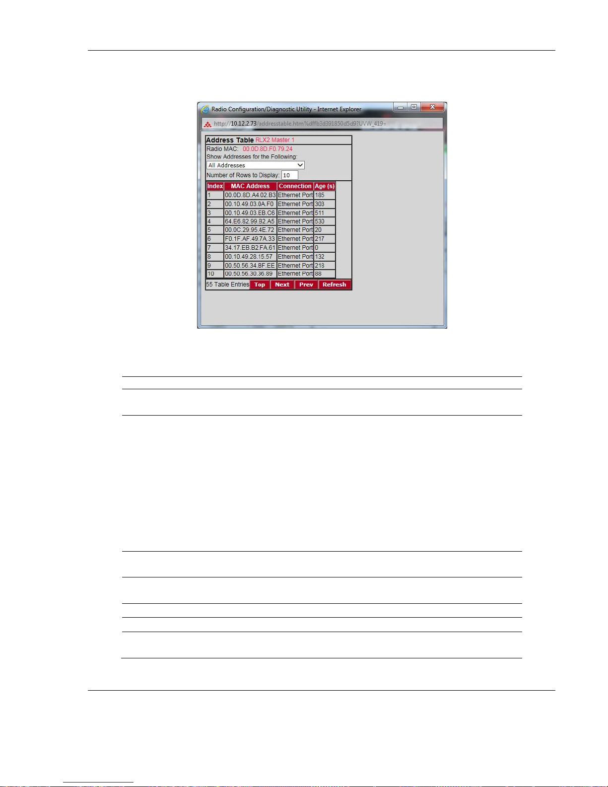
Field
Description
Radio MAC
The MAC address of the selected radio. The MAC ID is also printed on the side
of the radio.
Show Addresses for the
Following
Dropdown list to filter the address list. Options are:
All Addresses
Devices Out Ethernet Port
Directly Linked Radios/Clients
Devices beyond Direct RF Links
When the table is filtered to show only Directly linked radios/clients, an
additional RSSI column is listed, showing the Received Signal Strength from
each radio or client linked to the radio.
When the table is showing All Addresses and the RLX2 is operating as an
AeroScout sensor, each Wi-Fi device detected and reported to the AeroScout
engine will appear as: Detected Wi-Fi device.
Number of Rows to Display
Use this field to choose how many MAC addresses to display on this page.
Use the Next and Prev buttons to scroll through the available MAC addresses.
Index
Position in the list. Each page shows up to 10 devices. Use the Next and
Previous buttons to move up and down through the table.
MAC Address
The MAC address for the device.
Connection
The connection type.
Age (s)
The length of time (in seconds) since the radio last saw a packet from this
MAC address
Address Table
RLX2 Industrial Hotspot Series
The Address Table shows the port through which each MAC address is connected, along
with the age in seconds since the radio last saw a packet from this MAC address.
ProSoft Technology, Inc. Page 67 of 208
November 3, 2016
Page 68

RLX2 Industrial Hotspot Series
Field
Description
Top
Click the Top button to see the top of the table. The radio will display
updated data in the table entries.
Next / Prev
If the table has more MAC addresses than it can display in the window, use
the Next and Prev buttons to move up and down through the table.
Refresh
Click Refresh to update the table.
Port Status
The Port Status button shows all of the active ports on the radio. Above the table has
information about the current Spanning Tree including the MAC address of the “root”
device, and the timing parameters that are set for the current Spanning Tree. Each radio
can have up to 34 active ports – one Ethernet cable, one parent RF link, and up to 32
child RF links.
The primary reason for creating a Spanning Tree to that is allows you to create fully
redundant paths. If any single radio in a redundant path loses its connection, another
path still exists, and the connection will be updated and communication restored.
Page 68 of 208 ProSoft Technology, Inc.
November 3, 2016
Page 69

RLX2 Industrial Hotspot Series
Field
Description
Spanning Tree Protocol:
Wireless Ports
The Spanning Tree Protocol level for the wireless port (Rapid STP or STP).
Ethernet Port
The Spanning Tree Protocol level for the Ethernet port (Rapid STP or STP).
Edge Port
Displays Active or Inactive based on the setting of Ethernet Edge Port in the
Spanning Tree configuration dialog.
Spanning Tree Root: MAC
The MAC ID of the root device in the spanning tree.
Priority
Spanning Tree device with the lowest-priority value is elected the root of the
tree
Max Age
The length of time a port can stay enabled without any new spanning
updates.
Hello Time
The length of time between the transmission of spanning update packets.
Forward Delay
The length of time a port must listen for spanning information before being
activated.
#
Position in the list. Each page shows up to 10 ports. Use the Next and Previous
buttons to move up and down through the table.
Connection
This field indicates what the port represents: Ethernet, a Parent radio, or a
Child radio.
State
The current Spanning Tree state of the port. Possible states are Blocking,
Learning, Listening, and Forwarding. Forwarding packets can be transferred.
Designation
The Spanning Tree designation for the branch off the port. Possible
designations are Root (ports going to the root), Designated (ports going to a
branch), or Normal.
Path Cost
The cumulative cost of all wired and wireless links from the port to the
Spanning Tree root.
Designated Bridge
The Next bridge toward the Spanning Tree root for this port.
Top
Click the Top button to see the top of the table.
Next / Prev
If the table has more ports than it can display in the window, use the Next and
Prev buttons to move up and down through the table.
Refresh
Click Refresh to update the table.
ProSoft Technology, Inc. Page 69 of 208
November 3, 2016
Page 70

RLX2 Industrial Hotspot Series
The following illustration shows the IH Browser application provided with the radios.
Notice it shows the radio named Hematite_4F, linked to Amethyst_BD. This link is shown
with a red dotted line. Also visible is the level of redundancy in their network. Each of
the blue lines represents an alternate parent. From this view, it is easily shown how
much redundancy exists in their network.
To display the redundant paths, select the toolbar button denoting two "parents." To
view the redundancy on a per-radio basis, select the single Parent button, and then click
on the radio to view its available redundancies.
Page 70 of 208 ProSoft Technology, Inc.
November 3, 2016
Page 71

Basic Settings
Basic settings include:
Basic Wireless Settings
Wireless Security Settings
Access Settings
RLX2 Industrial Hotspot Series
ProSoft Technology, Inc. Page 71 of 208
November 3, 2016
Page 72

RLX2 Industrial Hotspot Series
Basic Wireless Settings
Note: Different versions of the RLX2 Radios support different functionality. There may be more or
fewer options on this page, depending on the version of the radio.
Use the settings in the Radio Network Settings panel under the Main tab to configure
the radios in the network. For more information on using these settings, see Installing
the Radios (page 47).
Page 72 of 208 ProSoft Technology, Inc.
November 3, 2016
Page 73

RLX2 Industrial Hotspot Series
Field
Description
Radio Name
Assign a unique name to each radio.
Network SSID
Assign a Network name (SSID) of up to 32 characters. The radio uses this
name in all network references. All radios in a network must have the same
SSID. SSID names are case-sensitive.
802.11 Mode
RLX2-IHNF
This control is only present on the RLX2-IHNF model. It allows the unit to be
configured to operate in 802.11 a/g mode or to operate in 802.11n mode
(default). In addition, it allows configuration of whether the unit will allow
use of 40 MHz wide channels for Child clients.
Note: The Parent radio link of a Repeater automatically uses a mode that is
compatible with the Parent settings. For example, an RLX2-IHNF may connect
to an RLX2-IHW master which only operates in 802.11a/g mode, and still use
802.11n mode for any Child Repeaters.
802.11a/g
The radio acts as an 802.11a radio on the 5 GHz band, and an 802.11g radio
on the 2.4 GHz band. Data rates will be limited to the 802.11 a/g rates (54
mbps maximum). 802.11n operational features will be disabled. It is not
necessary to select this mode for RLX2-IHNF radios to link to other RLX2 or
RLXIB series radios; they will link their best possible speeds regardless of
mode. This mode is not commonly used. It is mainly used to allow 802.11
a/b/g client devices that cannot link to 802.11n devices to work. One example
of such a device is the ProSoft 1734-AENTR wireless I/O client.
802.11n
Default operational mode of the RLX2-IHNF radio. All 802.11n features are
operational, and 20 MHz wide channels are used.
802.11.n wide
Utilizes adjacent pairs of 20 MHz-wide channels as a single 40 MHz-wide
channel. This allows the fastest data throughput to other 802.11n devices.
Only 802.11n devices can utilize this mode, but all RLX2 radios will link at their
best speed regardless of mode.
Channels in the 5 GHz band are 20 MHz apart, so 802.11n wide mode occupies
only two channels in that band. However, channels in the 2.4 GHz band are
spaced only five MHz apart, so 802.11n wide mode in the 2.4 GHz band
occupies eight adjacent channels! Since there are at most 13 channels in the
2.4 GHz band, and only three channels do not overlap others, it is not
recommended to enable wide mode on 2.4 GHz band channels.
Master
Click this button to configure a radio as a Master. The Master is the root radio
in a network. You must have at least one Master radio per network. For
redundancy, you can assign more than one Master to a network. For
information, see Redundancy.
ProSoft Technology, Inc. Page 73 of 208
November 3, 2016
Page 74

RLX2 Industrial Hotspot Series
Field
Description
Channel List (Master Radio)
The Channel List indicates the channel number, the band (2.4 GHz or 5 GHz) as
well as the frequency in MHz.
When the 802.11 Mode is set to ‘802.11n wide’, each entry shows the main
channel number first followed by the extension channel number if the
particular channel supports 40 MHz.
The main 20 MHz channel is used whenever sending frames at an 802.11 a/g
data rate (e.g., Beacons at 6 Mbits/s. The main and extension channels are
used together for 802.11n data rate transmissions. Note that the frequency
indicated when in 802.11n wide mode is the center of the 40 MHz channel
pair.
Important: The RadioLinx RLX2 radio is not supplied with an antenna. When
choosing an antenna for use with the RLX2 radio, you must choose one that
supports the frequency range set in the configuration for the radio.
Repeater
Click this button to configure a radio as a repeater. The repeater mode is the
normal radio mode for the network, while the master mode is more of a
special setting to establish the network channel and define the root of the
network tree. Repeater radios help extend the range of a network and help
create the signal "bridges" that allow networked radios to communicate. All
RLX2 radios are capable of repeating.
Bridging Client
This special mode supports cases where there are multiple Ethernet devices
that need to connect to any 3rd-party 802.11 a, b, g, or n Access Point (AP).
This mode uses a Layer 2 Network Address Translation mechanism and can
only work for IP-based protocols. If non IP-based protocols are to be used,
then pure Client mode should be used. For information on setting up a client,
see Configuring Clients.
Client
This is a special mode that allows you to transparently connect a single
Ethernet device to any non-ProSoft 802.11 a, b, g, or n Access Point (AP). To
the AP, the MAC address of the Ethernet device would appear to be an 802.11
wireless client. Client mode supports all network protocols.
Auto / Specify
Only choose "specify" if device does not send out any unsolicited Ethernet
packets. Try Auto first.
Client MAC
The MAC ID of the device connected to the radio, only if the device does not
advertise its MAC address.
Page 74 of 208 ProSoft Technology, Inc.
November 3, 2016
Page 75

Wireless Security Settings
RLX2 Industrial Hotspot Series
The Security Controls shown in the center panel will vary depending on the values of the
following controls:
Security Mode
802.11 Mode
Master Mode vs Repeater, Bridging Client, or Client Modes
As each of the Mode controls are changed on the web page, the set of controls in the
Security panel will automatically change to selections applicable to the selected mode.
Note: The controls will change to allow you to fully configure the Security Settings before applying
the changes.
Note: Newer firmware versions of the RLX2 Radios may support additional functionality.
Therefore, you may see more or fewer options on this page, depending on the version of firmware
included the radio you purchased.
ProSoft Technology, Inc. Page 75 of 208
November 3, 2016
Page 76

RLX2 Industrial Hotspot Series
Field
Description
Security Mode
This unit supports both Personal and Enterprise security modes, as well as Legacy WEP
encryption modes for interoperability with Legacy devices.
The following security mode settings are supported
None (not recommended)
Personal – Security mode using a pre-shared key for networks that don’t require
an authentication server.
Enterprise – Security mode requiring the use of an eternal RADIUS authentication
server
WEP – Legacy security setting using either a 64 or 128-bit key and WEP encryption.
Personal and Enterprise security modes may be used with the following:
WPA – Original protocol introduced to replace WEP.
WPA2 – Latest 802.11 security protocol conforming to the 802.11i standard.
WPA/WPA2 – Allows client devices to connect using WPA if they do not support
WPA2.
Encryption
AES is the preferred encryption mechanism as it is the most secure protocol supported
by the 802.11 standard. However, some legacy devices do not support AES and
therefore, you can choose combinations of legacy methods depending on the 802.11
mode setting.
Available encryption types are:
None – (Not recommended)
AES – Recommended setting. Can be used with all Personal and Enterprise modes.
TKIP – Only TKIP encryption. This setting is only available when in 802.11a/g mode.
The 802.11n standard does not allow TKIP as the only encryption mechanism.
AES and TKIP – Allows client devices that don’t support AES to connect. This setting
is available in all 802.11 modes.
TKIP and WEP128 – Allows client devices that don’t support TKIP to connect. This
setting is only available when in all 802.11a/g mode. Note that combinations
including WEP and AES are not allowed.
WEP128 – Legacy security setting using a 128-bit key and WEP encryption. This
setting is only available when the WEP security mode is selected.
WEP64 – Legacy security setting using a 64-bit key and WEP encryption. This
setting is only available when the WEP security mode is selected.
The following security settings are available:
Page 76 of 208 ProSoft Technology, Inc.
November 3, 2016
Page 77

RLX2 Industrial Hotspot Series
Field
Description
WPA phrase
WPA pass phrase of between eight and 63 normal keyboard characters. This control is
present when any of the “personal” security modes are selected.
WEP Key
For WEP64, enter either 5 normal text characters or 10 hexadecimal characters in the
WEP key field.
For WEP128, enter either 13 normal text characters or 26 hexadecimal characters in the
WEP key field.
MAC Filter
Restricts connections by MAC address. Check this field to restrict connections by MAC
address.
Edit Filter
Opens the MAC filter (page 83) form, allowing the specification of the MAC addresses
of devices to allow in the network.
Hide Network
SSID
Hides the Network SSID (Network Name) from other 802.11 users. Clients can connect
to the "hidden" network by typing the Network SSID.
The following topics describe each security setting.
Encryption Type
The preferred encryption type is WPA or WPA2 (Wi-Fi Protected Access) using AES. You
should only select TKIP for use with an older client radio that does not support AES or
select WEP (wired equivalency protocol) for use with an older client radio that does not
support AES or TKIP. For compatibility with clients that do not support WPA, you can
select TKIP+WEP128 as the encryption type. Older clients can connect to the RLX2 using
the WEP setting, but all other links will use the more secure WPA encryption.
Important: If the RLX2 model supports 802.11n rates and they are enabled, then all ‘TKIP only’
and TKIP/WEP options are disabled. If a client radio only supports TKIP, then use the AES & TKIP
option. If the client radio only supports WEP, then switch the 802.11 Mode control to ‘802.11 a/g
and then select the appropriate WEP setting in this control.
Important: If TKIP+WEP128 is selected, some clients using WPA might not be able to connect
unless you use a WEP key other than number 1, due to limitations in these clients. In such cases,
you should set a WEP key other than key 1 and set this same key for all clients that are using
WEP. See WEP key.
When the WEP Security mode is selected, the WEP128 or WEP64 encryption types are
available but neither are recommended.
WEP is the original security protocol used by 802.11 networks but should only be used if
interoperability with a legacy device is essential. Tools are available that allow an
attacker to break the WEP keys simply by sniffing an active WEP network for a few
minutes. WPA offers vastly better protection against attacks, for several reasons. WPA
distances the encryption key from the actual data by performing several algorithms to
ProSoft Technology, Inc. Page 77 of 208
November 3, 2016
Page 78

RLX2 Industrial Hotspot Series
create a ‘Session’ key before encrypting any data, and it performs dynamic key
management by changing keys frequently.
Note: If an RLX2 is set to use TKIP+WEP128, it will connect to other radios set to WPA only or
WPA+WEP, but it will not communicate with radios set to WEP only. Likewise, an RLX2 in client
mode with TKIP+WEP128 selected will not connect to an access point with WEP only selected.
WPA Phrase
If a WPA or WPA2 Personal Security Mode is selected, enter a WPA phrase of between
eight and 63 normal keyboard characters. This phrase automatically generates an
encryption key of 128 hexadecimal characters. This field is only available if you select
one of the ‘Personal’ security modes. The default WPA Phrase is: passphrase
WEP Key
A WEP key is a set of hexadecimal (hex) or ASCII characters used to encrypt data. This
field is only available when using WEP encryption type. Be sure to record the WEP
encryption key to retrieve if needed.
To create a 64-bit WEP key, enter five normal text characters in the WEP key field, which
converts the characters automatically to 10 hex digits. Alternatively, enter 10 hex digits
(0 to 9, a to f, A to F) directly in the WEP key field.
To create a 128-bit key, enter 13 normal text characters, which convert to 26 hex digits,
or enter 26 hex digits (0 to 9, a to f, A to F) directly.
Note: Clients often support more than one WEP key. Packets received can be decrypted using any
one of the keys if programmed, but packets are always transmitted with the "default" WEP key
number. If a transmit key number is set on the RLX2 radio, make sure all other radios and clients
have this key programmed. To set keys other than key 1 on some clients using Windows,
Advanced settings may be used.
Programming more than one key on the RLX2 radio requires setting the key number to
the key, entering the key, and saving the changes. Repeat these steps for each key to
program, saving after each one. Finally, change to the desired transmit key number if
necessary and save again (If "****" remains in the key field, the previously programmed
key will not be changed when changes are applied).
Page 78 of 208 ProSoft Technology, Inc.
November 3, 2016
Page 79

RLX2 Industrial Hotspot Series
Field
Description
IP Address
The IP address of the RADIUS server with which the Network Administrator has
registered this RLX2.
UDP Port
The UDP port number the RADIUS server is using to listen to Radius frames from this
RLX2. The default port number used for the Radius protocol is 1812.
Secret
The passphrase that was used when this RLX2 was registered to the RADIUS server.
This is used to validate that the Radius frames received on either end are legitimate.
Enterprise Mode Settings
When one of the Enterprise modes are selected in the Security Mode control, a set of
controls for Enterprise mode parameters is automatically displayed in the middle of the
Security Settings panel on the main web page of the RLX2. There are two sets of
controls; the first pertains to the RLX2 in Master mode, and the second when the RLX2 is
configured in Repeater or Client mode.
In Enterprise mode, the RLX2 authenticator communicates directly with the RADIUS
Server while it is relaying 802.1x frames received from an associating note’s Supplicant.
The following parameters must be configured on the Master in this Security Mode:
ProSoft Technology, Inc. Page 79 of 208
November 3, 2016
Page 80

RLX2 Industrial Hotspot Series
Field
Description
EAP Method
The EAP Method, sometimes referred to as the ‘outer protocol’ defines the
mechanism used to create a secure tunnel between the Supplicant and
RADIUS server during the first phase of the Authentication sequence. The
following EAP methods are supported:
EAP-PEAP – EAP method using the ‘Protected Extensible Authentication
Protocol’
EAP-TLS – EAP method based on X.509 certificates that provides for
mutual authentication. This is the most secure authentication
mechanism available for 802.11. Certificates are required both on
the RLX2 and the RADIUS server. The only authentication option
available for EAP-TLS is to use TLS for the inner protocol.
EAP-TTLS – EAP Tunneled TLS. Similar to EAP-PEAP.
Anonymous ID:
The identity request in the first phase of the exchange is sent in the clear.
The identity sent in this first phase can be set to an anonymous identity
(Ex. anon_user) or an anonymous identity at a domain (Ex. anon@xyz.com).
The real identity (username) will be sent encrypted after the EAP tunnel is
established in the second phase of the radius exchange.
Use this parameter if you are concerned about the username being sent in
the clear.
* Your IT department should specify what should be entered in this field
based on their RADIUS server(s) configuration.
Authentication Method:
The Authentication Method, sometimes referred to as the ‘inner protocol’
defines the mechanism used to authenticate the Supplicant of the RLX2 with
the RADIUS server. The following authentication methods are supported:
MS-CHAPv2 – Microsoft’s version of the ‘Challenge Handshake
Authentication Protocol’ (CHAP). This method provides mutual
authentication between the Supplicant and the RADIUS server,
using a user name and password and challenge text responses.
MD5 – ‘Message Digest’ cryptographic hashing algorithm based on a
user name and password.
TLS – Certificate-based inner authentication protocol.
User Name:
Enter the User Name of the account that is to be authenticated. When using
EAP-TLS, this represents the identity of the entity assigned to the device
certificate being used.
Password:
Required field when using EAP-PEAP or EAP-TTLS with MS-CHAPv2 or MD5.
Enter the password of the account corresponding to the user name.
Certificates
Opens a window that displays the current certificates installed in the RLX2,
and provides controls to upload new certificates into the unit.
Note: The RLX2 does not ship with any certificates installed.
When in Repeater or Client mode, the RLX2 Supplicant communicates via its Parent
RLX2’s authenticator with a RADIUS server. Several different authentication protocols
are available and can be set using the following parameters.
Page 80 of 208 ProSoft Technology, Inc.
November 3, 2016
Page 81

RLX2 Industrial Hotspot Series
Field
Description
Certificate Type
Select the type of certificate that you will be uploading. It is important that
this is set correctly as the RLX2 does not distinguish between them in any
other way.
Certificate Passphrase
If the certificate is encrypted, enter the passphrase that was used to create it
on the RADIUS server.
File Location
Browse to locate the certificate file on the local PC that is to be uploaded.
Certificate Management
When using Enterprise-level security, some EAP methods require the use of X.509
certificates. The Certificate Management web page allows the uploading of certificate
files to the RLX2.
There are two certificate types; a certificate from a ‘Certification Authority’ used to
authenticate the RADIUS server to the RLX2 supplicant, and device or client certificate
created by the RADIUS server for the RLX2. The RLX2 is able to hold one of each
certificate type.
If PEAP authentication is used, you’ll need a CA Certificate (to authenticate the RADIUS
server) and a username and password.
If EAP-TLS is used, you’ll need a CA Certificate, a Client Certificate and Private Key
(contained in a single p12 file) to authenticate the client. The p12 file is encrypted and
requires a password.
The IT person will provide you with the appropriate files that you’ll need to load to the
RLX2 Repeater.
The following controls are used for uploading a certificate:
ProSoft Technology, Inc. Page 81 of 208
November 3, 2016
Page 82

RLX2 Industrial Hotspot Series
Configuring the RLX2 Repeaters with Certificates
Obtain the required certificate files from your IT person and use the following procedure
to upload these files to the RLX2 Repeater.
1. Open the web page for the RLX2 repeater to be configured.
2. Select the EAP Method (PEAP or EAP-TLS).
3. Enter the Username.
4. Click Certificates to enter the certificate files.
5. Select either CA or Device (client).
A CA Certificate is required for both PEAP and EAP-TLS. This is used to authenticate
the server’s certificate. Additionally, for EAP-TLS, a client certificate and private key
are required.
6. Enter the CA Certificate file created previously (CAcert.pem) and apply it.
7. Enter the Client Certificate combined file (clientcert.p12) and the password
associated with the file. Then click Apply.
8. Apply changes on the main page and attempt to connect to the Master.
Page 82 of 208 ProSoft Technology, Inc.
November 3, 2016
Page 83

Field
Description
Add MAC
Enter the MAC address to add. This address will appear in the list after you
click the Add MAC button.
Delete
Deletes the selected MAC address from the list.
Address
List of MAC addresses configured.
Top
Displays the top of the list.
Next / Prev
Navigates up and down through the address list.
Upload File
To assign the same list of MAC addresses to several radios conveniently,
open a text editor such as Notepad.exe. Enter addresses in hexadecimal
format, one MAC address per line, including periods. When finished, save
the document. In the MAC Filter window, click Browse to select the text file,
click Upload File to upload the list of MAC addresses.
Choose File (Browse)
Navigates to a prepared text file of MAC addresses on the appropriate drive
and folder, and click the Upload File button.
MAC Filter
RLX2 Industrial Hotspot Series
Hide Network SSID
If the radio network is to be hidden from other 802.11 users, click the Hide Network
SSID check box in each radio to be hidden. With the SSID hidden, the network does not
show up when other clients scan for an access point. Clients can still connect to the
"hidden" network by typing the Network SSID into their device’s control panel.
ProSoft Technology, Inc. Page 83 of 208
November 3, 2016
Page 84

RLX2 Industrial Hotspot Series
Advanced Settings
It is important to allow many industrial protocols to communicate properly over the
RLX2 radios. The standard 802.11 AP operation for transmitting broadcast messages is
to accumulate them and transmit them on specific time intervals. This allows clients that
are in power-save mode to wake up at the synchronized time interval and receive the
broadcast packets. However, the power-save mode is rarely used in industrial networks.
Additionally, many industrial protocols utilize multicast traffic, which is sent as
broadcast messages over the wireless network. By enabling immediate broadcasting,
these multicast messages are not delayed by waiting for the next time interval to occur.
This results in improved network performance.
The settings allow you to configure the transmission rate and broadcast mode to
optimize this radio’s use on an industrial network.
Advanced settings include:
Advanced Wireless Settings
Roam Control
Location Services
Personality Module
Password Change
Page 84 of 208 ProSoft Technology, Inc.
November 3, 2016
Page 85

RLX2 Industrial Hotspot Series
802.11n mode, Mbit/s
802.11n wide mode,
Mbit/s
MCS
Index
Active
Antennas
800 ns GI
400 ns GI
800 ns GI
400 ns GI
0
1, 2 or 3
6.50
7.20
13.50
15.00
1
1, 2 or 3
13.00
14.40
27.00
30.00
2
1, 2 or 3
19.50
21.70
40.50
45.00
3
1, 2 or 3
26.00
28.90
54.00
60.00
4
1, 2 or 3
39.00
43.30
81.00
90.00
5
1, 2 or 3
52.00
57.80
108.00
120.00
6
1, 2 or 3
58.50
65.00
121.50
135.00
7
1, 2 or 3
65.00
72.20
135.00
150.00 8 2 or 3
13.00
14.40
27.00
30.00
9
2 or 3
26.00
28.90
54.00
60.00
10
2 or 3
39.00
43.30
81.00
90.00
11
2 or 3
52.00
57.80
108.00
120.00
12
2 or 3
78.00
86.70
162.00
180.00
13
2 or 3
104.00
115.60
216.00
240.00
14
2 or 3
117.00
130.00
243.00
270.00
15
2 or 3
130.00
144.40
270.00
300.00
Advanced Wireless Settings
Max Data Rate
For RLX2-IHNF only, MCS rates from 0 to 7 are available with one antenna. This is the
default configuration. To select rates of 8 and above, configure the Active Antennas
field to be A and C, or A, B, C.
The radio automatically selects the Guard Interval (GI) based on current operating
conditions. The system attempts to use a 400 microsecond GI, but will fall back to an
800 microsecond GI if excessive data corruption is detected. The radio will periodically
attempt to resume using a 400 microsecond GI as conditions improve. A 400
microsecond GI results in about 11% more throughput than using an 800 microsecond
GI. The user has no control of the GI.
ProSoft Technology, Inc. Page 85 of 208
November 3, 2016
Page 86

RLX2 Industrial Hotspot Series
For RLX2-IHW/A/G only: Advanced Wireless settings with Max Data Rate open and
closed.
Note that the Active Antennas field is present in the IHW providing options for one or
two antennas.
Max Basic Rate
In addition to the Data Rate setting which controls generic data traffic, the Basic Rate
adjusts the rate at which control packets such as beacons and acks are sent as well as
packets that need to go to the entire network such as broadcasts.
Because the packets are intended for the whole network, the Max Basic Rate setting of
the Master is advertised to each of the radios in the network through beacons.
Each radio, other than the master, then inherits the Max Basic rate setting of the
master. Therefore, the setting only needs to be made in the Master radio. The settings
of all other radios are discarded.
Page 86 of 208 ProSoft Technology, Inc.
November 3, 2016
Page 87

Optimize For:
RLX2 Industrial Hotspot Series
The following options are available:
Manual
rd
3
Party Clients
RLX2 Bridging
Secure Bridging
3rd Party Clients optimizes these controls for peer devices such as laptops, tablets,
phones or any other Wi-Fi devices that perform regular power savings and are expected
to connect to this RLX2. If this setting is not used, then these client devices may have
difficulty in finding the network’s SSID, and their communication may be erratic due to
broadcasts not being transmitted when expected. RLX2 bridging will still function,
although the RLX2s will be responding to all scanning client devices which may introduce
some jitter to data being transferred.
RLX2 Bridging optimizes immediate Broadcasts, Blocks General Probes and range for
operation when peer devices are primarily other RLX2s.
Secure Bridging is similar to RLX2 bridging but also enables the Prosoft-Only client
control which rejects any connections from 3rd-Party clients.
ProSoft Technology, Inc. Page 87 of 208
November 3, 2016
Page 88

RLX2 Industrial Hotspot Series
Immediate Bcasts
Forward multicast traffic immediately, rather than waiting for specific time intervals.
Ignore Probes
Do not respond to general probe requests that are not specific to the radio’s SSID.
ProSoft-only Clients
Rejects connections from 3rd-party clients. See Secure Bridging.
Range (km)
Allows the radios to account for round trip delays. The Range settings should be the
same in all radios in the network and should be at least large enough to account for the
length of any links. However, increasing the Range beyond what is necessary can cause a
slight decrease in throughput. The default Long range is 25km, which is valid for all
operating modes of all radios. Reducing the range setting for systems at closer range
may improve throughput.
TX Attenuation
Sets the amount the output power of the radio is attenuated. Zero implies no
attenuation meaning the radio uses full power.
Active Antennas
This control is available on the RLX2-IHNF and RLX2-IHW radios.
RLX-IHNF
The default is set to A, B, C (for a three connector MIMO antenna). The other options
are A Only (for one antenna) and A, C (for two antennas). Note that if two antennas are
used, they must be attached to the ANT A and ANT C antenna connectors
MIMO antennas generally will have three connections so all three antenna ports must
be activated. In general, operation with three antenna ports will give best performance.
When more than one antenna port is active, the radio will monitor the signal appearing
at all antenna ports and dynamically select the port(s) with the best signal. However,
there are situations where performance may improve if fewer antenna ports are active.
If radios are very close together (typically a few feet), all three antenna ports will receive
essentially identical signal strengths and the radio may continuously change antenna
ports, resulting in degraded performance.
Page 88 of 208 ProSoft Technology, Inc.
November 3, 2016
Page 89

RLX2 Industrial Hotspot Series
RLX2-IHW
The default is set to 1 antenna. The main connector labeled ‘Antenna’ is used. If RX
diversity is desired to improve performance in high multipath environments a second
antenna can be added to the connector labeled ‘Rx Only’ and the Active Antenna
control set to 2 Antennas.
Roam Control
In roaming applications, a mobile platform equipped with an RLX2 Repeater roams from
one Master’s coverage area to another. By default, an RLX2 Repeater roams
autonomously by calculating the cost for each roam candidate based only on RSSI and
hop count. A lower cost determines when a better Parent candidate is present.
The RLX2 employs aspects of the Fast Transition (FT) standard to reduce the time it
takes to roam. An FT Roam will be used if the Repeater, the current Parent, and the next
Parent all have FT enabled. FT Roaming can be turned off by checking the Disable FT
checkbox resulting in normal non-FT Roams.
Independent to the type of Roam, there are several limitations when the RLX2s are
operating in autonomous roam mode that can be overcome by using Parent Assisted
Roaming.
Given that the current RLX2 only has one radio module, all Masters, by
necessity, have to be on the same Channel to allow the roaming Repeater to
detect them.
In applications where the mobile platform is travelling a known path, it is
necessary to have an unambiguous option when it reaches a roam point. If
multiple Parents are in range at the roam point, it may decide to roam to the
wrong Parent.
The Repeater’s Roam Threshold and Parent Margin settings are used for every
roam. Due to topology variances, there may be one or two coverage areas that
would operate better with different settings for these roam parameters.
ProSoft Technology, Inc. Page 89 of 208
November 3, 2016
Page 90

RLX2 Industrial Hotspot Series
Field
Description
None
When checked, this control negates all others so that no roam parameters are
advertised to Child Repeaters.
Next Parent
When checked, this advertises the unit that a Child Repeater should roam to next.
A select-edit box is present that is automatically populated with all the RLX2 units
with the same SSID that are on the same Ethernet network as a unit.
Each entry is represented by the Name of the RLX2, so it is important that each
RLX2 be given a unique name. If the desired next Parent has not been detected
because it is not currently powered up or attached to the network, it will not
appear in the list. In this case, its MAC Address can be manually entered into the
edit box. Once saved, this MAC Address appears in the select box until that unit is
detected on the Ethernet at which point it will switch to displaying the unit’s name.
When an advertised Next Parent is on the same channel as the current unit, the
Child Repeater will roam to the Next Parent when the Next Parent’s cost is lower
than its current parent’s. When the advertised Next Parent is on a different
channel, then the Roam Threshold is used to make the roam decision.
Roam Threshold
When checked, this enables advertising of the Roam Threshold that a Child
Repeater should use. This Roam Threshold overrides the Child Repeaters
equivalent setting but only while the Child Repeater is associated to this unit. If the
Parent is not advertising a Roam Threshold, then the Child Repeater will revert to
using its own value configured in the Parent Link Settings dialog box.
This setting is critical when a Next Parent is also being advertised and that parent is
configured to be on a different channel than this unit. The Child Repeater uses this
threshold to determine when to switch to the Next Parent’s channel and associate
with it. The installer must ensure that at a point where the current Parent’s RSSI
goes below the threshold, the Next Parent is in range. Otherwise, the roam will fail.
The main point to remember is that a Child Repeater will not roam while its current
Parent’s RSSI is higher than the current Roam Threshold value. In the case where a
Next Parent is not being advertised or the Next Parent is on the same channel, then
the Cost comparison to determine when to roam only occurs once the current
Parent’s RSSI is below the Roam Threshold. This allows the roam point to be
controlled when a mobile platform travels a known path.
Parent Margin
When checked, this enables the advertising of the Parent Margin that a Child
Repeater should use. This Parent Margin overrides the Child Repeater’s equivalent
setting, but only while the Child Repeater is associated to this unit. If the Parent is
not advertising a Parent Margin, the Child Repeater will revert to using its own
configured value. (see the Parent Link Settings help page description of Parent
Margin).
The following settings allow for Parent Assisted roaming by advertising these parameter
values to any Child Repeater that associates to this unit. Each parameter can be enabled
separately using a checkbox. Only enabled parameters are advertised to Child
Repeaters.
Page 90 of 208 ProSoft Technology, Inc.
November 3, 2016
Page 91

RLX2 Industrial Hotspot Series
Location Services
This control enables the RLX2’s support for AeroScout™ Location Services. If not
present, the feature has been disabled at the factory.
Tag Enabled Mode forwards any Tag Reports receive to the AeroScout location
engine.
Tag and MU Enabled forwards tag Reports and well as any mobile unit packets
heard from on the RLX2’s channel.
The AeroScout feature listens on Port 1141 for commands from the AeroScout engine.
ProSoft Technology, Inc. Page 91 of 208
November 3, 2016
Page 92

RLX2 Industrial Hotspot Series
SD Auto Write Enable
Enables the unit to write a copy of its Configuration to the SD Card whenever
new settings are saved from any pages of the unit's web interface. Previous
Configuration files are renamed with a unique file name which allows
auditing of changes made to the unit's settings.
SD Auto Clone Enable
Enables the unit's Clone function. On power up if an SD Card is present that
has a Configuration file different from the unit's current Configuration the
unit will adopt the settings from the SD Card. If the Configuration matches or
there is no Configuration file on the SD Card then no action is taken. On
inserting an SD Card into a running unit, if the Configuration file found on the
SD Card will result in the unit's settings being changed on Power up or Reset,
a warning is indicated by flashing the Signal Strength, MOD and NET LEDs.
In order to save this control as enabled, either an SD Card must not be
present, or the SD Auto Write Enable control must also be checked when
saving. If these conditions are not present the control will be disabled before
saving, to prevent the unit from reverting back to a Configuration file on the
SD Card after reset.
To adopt the Configuration file on an SD Card when this control is already
enabled, simply insert the SD Card and power cycle the unit. If this control is
not enabled, first enable and save the setting without the SD Card inserted
and then insert the SD Card and power cycle the unit.
NOTE: Do not enable Auto Write if you do not want the active Configuration
file on the SD Card to be replaced when the unit adopts and saves the SD
Card's current Configuration file.
Write SD Card
Immediately writes a copy of the unit's Configuration file to the SD Card,
independent of the Auto Write check box setting. Note that the
configuration files are in a binary format so sensitive data (e.g. passwords,
encryption keys) cannot be easily read from the files.
Personality Module
Change Password
This section allows you to change the password to the web interface.
Page 92 of 208 ProSoft Technology, Inc.
November 3, 2016
Page 93

RLX2 Industrial Hotspot Series
Field
Description
Parent Selection Method
Automatically Choose Best
The Automatic Parent Selection algorithm uses a calculation to create a
“cost” metric for each possible parent radio that it detects.
In the calculation the radio includes,
RSSI - Stronger signals receive a lower cost.
Hop Count - Fewer hops from the Master radio is given preference and
therefore a lower cost
Choose this setting to allow the radio to determine the best parent to select.
Parent Branch Length
RLX2 radio will choose its parent strictly by the number of repeaters between
it and the Master radio. If a Branch Length of 1 is chosen, the RLX2 radio will
link only to the Master radio. If a Branch Length of 2 is chosen, the RLX2 radio
will link only to another RLX2 radio that is linked to the Master radio, and so
on. If multiple candidates are available at a particular hop count, the RLX2
chooses the Parent that has the smallest cost.
Parent Link Settings
Parent Link Settings allow you to specify how a Repeater, Bridging Client, or Client radio
connects to the network. Access the Parent Link settings via the Parent Link tab.
ProSoft Technology, Inc. Page 93 of 208
November 3, 2016
Page 94

RLX2 Industrial Hotspot Series
Field
Description
Preferred Parent
RLX2 radio will select its parent from a list of possible parents specified by the
user. When this option is selected, a list of up to eight MAC Address entry
fields become visible. The user enters one or more MAC Addresses of the
Radios that the RLX2 must choose from.
Best in List
When Best in List is selected the radio will select its parent using the
Automatic Parent Selection algorithm, but it will limit the selection to
the list of radios in the list. Therefore, the radio in the list with the
lowest cost according to the algorithm will be chosen as its parent.
Follow List Priority
When Follow List Priority is chosen the radio will select its parent from
the list giving preference to the 1st entry followed by the 2nd entry and
so on.
2.4 GHz Parents Only
Forces the RLX2 to only select parents that are operating in the 2.4 GHz
band.
5 GHz Parents Only
Forces the RLX2 to only select parents that are operating in the 5 GHz
band.
Repeater Parameters
Signal Strength Threshold
When the signal from a parent reaches a high enough value, a stronger
signal will not improve the quality of the link any further. For signals that are
above that threshold, only fewer hops from the Master give preference. The
threshold can be adjusted here. Another way to consider this in Fast Roam
applications is that the RLX2 will not Roam to a new Parent at the same hop
count level until its current Parent’s RSSI goes below (weaker) than this
value.
Default Parent Margin
In Fast Roam applications where the RLX2 is on a mobile platform, or there is
a lot of movement in the environment causing RSSI levels to fluctuate, it is
desirable to have the RLX2 stick to its current Parent unless a better Parent’s
RSSI is stronger than this value. This margin value is added to the current
Parent’s RSSI prior to calculating its cost. It is desirable to ‘roam’ to a new
Parent prior to losing the connection with the current Parent which results
in data loss.
A value too small in this parameter can lead to an RLX2 ping-ponging back
and forth between two Parents as the RSSI levels fluctuate. A value too large
could result in a roam not occurring up to the point where the unit moves
out of range, even though a candidate exists that is actually better than the
current Parent.
The default value is 5 dB. Larger values (10-15 dB) should be used to prevent
false roams from occurring due to temporary RSSI inversions between the
current Parent and another candidate, with the caveat of course, that a
roam point exists where the RSSI difference between the current Parent and
the new Parent is greater than this margin.
Page 94 of 208 ProSoft Technology, Inc.
November 3, 2016
Page 95

RLX2 Industrial Hotspot Series
Field
Description
Rate to Parent
The default setting is Auto which allows the radio to select the best rate to
use to the parent radio, and adapt over time. Specify a fixed rate rather than
auto for example if the link to the parent has a low signal strength in which
case fixing a lower rate can improve performance.
The actual rate used between this radio and its parent is the lower value of
this setting and the Max Data Rate setting in the parent (see Max Data Rate).
So use these two controls in conjunction if desired to tailor the rate of each
parent link.
Note: When configuring an RLX2-IHNF, this control is only enabled if the 802.11
Mode control on the main page is set to 802.11a/g mode.
Allow Children
This parameter controls whether the RLX2 Repeater will act as a Parent to
other 802.11 radios. Selecting ‘No’ will disguise the RLX2’s SSID thus
preventing other 802.11 devices from finding it. Fast Roam applications take
advantage of this where it is not desirable to have anything connect to an
RLX2 Repeater that is itself, moving and roaming.
Optimize Fast Roam
Parameters
In typical Fast Roam applications a Repeater is installed on a mobile pallet or
platform and a set of Master units forms a backbone infrastructure network,
through which the Repeater must roam. To obtain Fast Roam times,
Spanning Tree must be disabled and SSID's not hidden on the Master. The
Repeater should be configured to not allow child Repeaters and to use a
Signal Strength Threshold set high enough such that RSSI is used to
determine the link cost to a parent.
Checking the checkbox in this section automatically sets these parameters
accordingly along with a predetermined optimum value for the cost
threshold. Unchecking it will revert the parameters back to their previous
values before the check box state was saved.
Note: Spanning Tree configurations and Hide SSID must be disabled manually on all
Master units as this dialog box is only accessible when in Repeater, Client, or
Bridging Client mode.
It is always possible to subsequently change any of these parameters if it is
so desired, for example to set a different value for the Signal Strength
Threshold. If this is done then the control will not display as checked as it
will only display as checked if all three parameters have the preset values.
ProSoft Technology, Inc. Page 95 of 208
November 3, 2016
Page 96

RLX2 Industrial Hotspot Series
Advanced Network Settings
IGMP Settings
IGMP settings are found under the Advanced Network Settings tab.
RLX2 radios support IGMP v1 and v2. The default operation of the RLX2 radios is to have
IGMP functionality enabled, although the user can disable IGMP entirely. Additionally,
the user can specify settings associated with IGMP filtering and snooping. Unknown
multicast addresses can be sent to all ports (flood) or to none (filtered) by changing the
IGMP Multicast Filtering option. The user can specify whether the radio will generate
IGMP queries, and configure the query interval time.
By RFC specification, only one device on a network should generate IGMP queries. As
such, RLX2 radios will only send a query if another device has not sent a query within its
Query Interval setting, even if Query Generation is enabled.
Page 96 of 208 ProSoft Technology, Inc.
November 3, 2016
Page 97

Field
Description
IGMP Multicast Filtering
Disabling filtering will cause the radio flood multicast packets to all ports.
Default Propagation Action
Determines how to handle multicast addresses that are not in the radio’s
address table. Choices are Flood or Filter.
IGMP Query Generation
Enables or disables query generation from this radio.
IGMP Query Interval
Number of seconds between queries (if not pre-empted by a query from
another device)
Multicast State Count
Number of queries generated before a device is removed from the multicast
group on this radio if no response is received.
Field
Description
Enable Spanning Tree
Spanning Tree is enabled when this box is checked. Without spanning tree,
redundant connections might exist if multiple radio links are created in parallel
with each other. Redundant connections are blocked only if spanning tree is
enabled. Additionally, spanning tree is used to flush the Ethernet switch table
when the network topology changes as described in the section on Automatic
Parent Selection.
All RLX2 models support Rapid Spanning Tree (RSTP), and will default to this
mode when enabled.
The recommended setting for spanning tree is “Enabled”.
Ethernet Edge Port
Because RSTP is an active protocol, it depends on communication between
RSTP devices. If no RSTP device is connected to the radio’s Ethernet port, the
handshake cannot take place. In this case RSTP reverts to STP. This means that
the Ethernet port will be forced to adhere to the timer based transition
protocol of STP.
Therefore on network transitions and power up, communications will not be
allowed over the Ethernet port for 30 to 45 seconds. This setting is an
indication that no redundant connections exist out this port and
communication can immediately be allowed. If for some reason a BPDU is
received on this port, the RSTP protocol will negotiate properly and handle any
possible redundant paths.
The recommended setting for Ethernet Edge Port is "Enabled".
STP Settings
RLX2 Industrial Hotspot Series
ProSoft Technology, Inc. Page 97 of 208
November 3, 2016
Page 98

RLX2 Industrial Hotspot Series
Field
Description
Bridge Times
Configures the timing intervals to use.
Priority
Determines who should be the root of the RSTP. The RSTP device with the
lowest priority becomes the root. The accepted standard value for this is
32768. If wired switches exist in the network that support RSTP, they should
always be allowed to be the root.
Set this value to 32769 to prevent the radio from being the root over a wired
switch. Use this setting when a radio is configured to be a Master.
Set this value to 32770 when the radio is configured as a Repeater. In this way,
if only RLX2 radios exist in the network, the Master radio will become the root.
Hello Time
Rate at which BPDUs are sent out. The industry standard is 2 seconds.
Max Age
Measures the age of the received protocol information recorded for a port and
ensures this information is discarded when its age limit exceeds the value to
the maximum age parameter recorded by the switch. The timeout value for
this timer is the maximum age parameter of the switches.
Forward Delay
Monitors the time spent by a port in the learning and listening states. The
timeout value is the forward delay parameter of the switches.
Path Costs
RSTP and STP algorithms use a cost to determine which connections should be
used. The "spanning tree" is formed by determining the least cost paths from
any RSTP device back to the root.
Wireless
Gives preference to a wired connection, set the Wireless cost to 200.
Ethernet
Gives preference to a wired Ethernet connection, set the Ethernet cost to 100.
Rapid Spanning Tree Functionality
Rapid Spanning Tree (RSTP) is an advanced networking function that shuts off ports as
necessary to prevent data packet loops when more than one network path is available.
If loops are created in an Ethernet network, packets can be circulated endlessly,
consuming all the bandwidth and making the network unusable.
RSTP allows users to create truly redundant connections between any two points in the
network. The radios detect the redundant paths and keep one connection alive for
communications. If the Primary connection fails for any reason, the secondary
connection is quickly transitioned to a state to forward packets, allowing the network to
adapt itself to handle problems without customer intervention.
RTSP uses active communications between network devices to propagate changes in the
network and to cause transitions to occur much more quickly. Because RTSP is an IEEE
standard, IH radios work in conjunction with wired Ethernet switches to form a
redundant network.
Each RSTP device (RLX2 radio or Ethernet switch) communicates with other RSTP
devices in the network via packets called Bridge Protocol Data Units (BPDUs). BPDUs are
sent out each of the devices ports. In a wired switch, this would be from each of the
Ethernet ports. In an RLX2 Radio, in addition to the Ethernet port, each wireless link is
Page 98 of 208 ProSoft Technology, Inc.
November 3, 2016
Page 99

RLX2 Industrial Hotspot Series
considered a port. These BPDUs are the communications means to allow each RSTP
device in the network to make sure that the proper connections still exist.
In the following illustration, the port status dialog box is obtained by clicking on the Port
Status button on the main RLX2 web page. It shows a list of all ports and their state. In
this example, the RLX2 Radio has 4 RSTP "ports":
Ethernet port (1)
A port for its parent connection (2)
A port for each of its two child connections (11 and 12).
BPDUs are sent out the port at a rate called the "Hello Time". The accepted standard
value for this is 2 seconds. If a radio (or any other RSTP device) does not get a BPDU for
2 Hello Times, it assumes the RSTP device that had been there is no longer available. It
can then open an alternate path if one is available. This process is much like the STP
process. If other devices on the network are not operating in rapid spanning tree mode,
the radio will revert to normal spanning tree operation on a per-port basis.
RSTP provides a performance enhancement over STP operation. By comparison, the
radio using the STP algorithm would revert its port to the listening state, and then to the
learning state, before returning to the forwarding state. Each of these states takes at
least 15 seconds, during which the STP devices are listening for BPDUs to re-negotiate
the network topology. The advantage of using the RSTP functionality is that is uses
active handshaking between adjacent RSTP devices to re-negotiate the network
topology. This process takes one to two seconds.
Each RLX2 Radio contains a switch table, which tells it how to forward Ethernet packets
to get them to their proper destination. When the network topology changes, the RLX2
Radio the Ethernet switch table is flushed immediately. This allows it to pass traffic
immediately over the new network topology and learn the configuration in the process.
Until the learning is complete, the packets are broadcast to their destination. As each
packet is seen and the switch table rebuilds, the radios return to directing packets to
their destinations.
ProSoft Technology, Inc. Page 99 of 208
November 3, 2016
Page 100

RLX2 Industrial Hotspot Series
Field
Description
Enable
Enables the following SNMP Agent settings.
Allow Any Manager
Allows any user to change the radio settings from any computer using SNMP.
Allow IP
Restricts access to an SNMP manager with a particular IP address. Enter the
IP address in the Allow IP field.
Community String
Enter a "community string" (essentially a password) that a manager must use
to access the radio’s SNMP agent.
Permission
Select the permission level to assign to this radio.
Read only
An SNMP Agent can view but cannot modify radio settings.
Read/Write
An SNMP Agent can view and modify radio settings.
SNMP Agent Settings
SNMP is a network management protocol that is often used with TCP/IP and Ethernet.
As an alternative to using the Radio Configuration / Diagnostic Utility, changing radio
settings and viewing diagnostics can be done in an SNMP manager application.
The RLX2 SNMP agent supports SNMP protocol version 1.4 and 2.
MIBs:
RFC12133-MIB (partial; internet.mgmt.MIB-2.system, .interfaces, .snmp)
ROMAP-MIB (included on the DVD; internet.private.enterprises.romap)
It also supports a selection of standard SNMP traps, including Cold Start, which is sent
when the radio initializes.
Page 100 of 208 ProSoft Technology, Inc.
November 3, 2016
 Loading...