

Page 1
ICX30-HWC
Industrial Cellular Gateway
3G Cellular (M2M)
June 22, 2015
USER MANUAL
Page 2

Your Feedback Please
We always want you to feel that you made the right decision to use our products. If you have suggestions, comments,
compliments or complaints about our products, documentation, or support, please write or call us.
ProSoft Technology
5201 Truxtun Ave, 3rd Floor
Bakersfield, CA 93309
+1 (661) 716-5100
+1 (661) 716-5101 (Fax)
www.prosoft-technology.com
support@prosoft-technology.com
ICX30-HWC User Manual
June 22, 2015
ProSoft Technology®, is a registered copyright of ProSoft Technology, Inc. All other brand or product names are or
may be trademarks of, and are used to identify products and services of, their respective owners.
In an effort to conserve paper, ProSoft Technology no longer includes printed manuals with our product shipments.
User Manuals, Datasheets, Sample Ladder Files, and Configuration Files are provided on the enclosed DVD and are
available at no charge from our web site: http://www.prosoft-technology.com
Content Disclaimer
This documentation is not intended as a substitute for and is not to be used for determining suitability or reliability of
these products for specific user applications. It is the duty of any such user or integrator to perform the appropriate
and complete risk analysis, evaluation and testing of the products with respect to the relevant specific application or
use thereof. Neither ProSoft Technology nor any of its affiliates or subsidiaries shall be responsible or liable for
misuse of the information contained herein. Information in this document including illustrations, specifications and
dimensions may contain technical inaccuracies or typographical errors. ProSoft Technology makes no warranty or
representation as to its accuracy and assumes no liability for and reserves the right to correct such inaccuracies or
errors at any time without notice. If you have any suggestions for improvements or amendments or have found errors
in this publication, please notify us.
No part of this document may be reproduced in any form or by any means, electronic or mechanical, including
photocopying, without express written permission of ProSoft Technology. All pertinent state, regional, and local safety
regulations must be observed when installing and using this product. For reasons of safety and to help ensure
compliance with documented system data, only the manufacturer should perform repairs to components. When
devices are used for applications with technical safety requirements, the relevant instructions must be followed.
Failure to use ProSoft Technology software or approved software with our hardware products may result in injury,
harm, or improper operating results. Failure to observe this information can result in injury or equipment damage.
© 2015 ProSoft Technology. All Rights Reserved.
Printed documentation is available for purchase. Contact ProSoft Technology for pricing and availability.
Page 3
Agency
ATEX
CE
CSA/CB Safety
ETSI
FCC/IC
PTCRB
UL/cUL
Important Safety Information
A This Equipment is Suitable For Use in Class I, Division 2, Groups A, B, C, D or Non-Hazardous Locations Only.
B WARNING - EXPLOSION HAZARD - Substitution of Any Components May Impair Suitability for Class I, Division
2.
C WARNING - EXPLOSION HAZARD - Do not disconnect equipment unless power has been removed or the area
is known to be non-hazardous.
D Device must be powered by a Class 2 Power Source.
E Device is open-type and is to be installed in an enclosure suitable for the environment that utilizes a tool
removable door/cover.
F The RS-232 serial connector, Ethernet connector and I/O terminal block are not for use in Hazardous Locations;
they are only for diagnostics and set-up only.
G When Antenna is installed into ultimate enclosure, it must be threaded to appropriate port to ensure mechanical
securement.
Agency Approvals and Certifications
Do not operate the ProSoft Technology Wireless products in areas where blasting is in progress, where explosive
atmospheres may be present, near medical equipment, near life support equipment, or any equipment which may be
susceptible to any form of radio interference. In such areas, the ProSoft Technology Wireless products MUST BE
POWERED OFF. The ProSoft Technology Wireless products can transmit signals that could interfere with this
equipment.
Do not operate the ProSoft Technology Wireless products in any aircraft, whether the aircraft is on the ground or in
flight. In aircraft, the ProSoft Technology Wireless products MUST BE POWERED OFF. When operating, the ProSoft
Technology Wireless products can transmit signals that could interfere with various onboard systems.
Note: Some airlines may permit the use of cellular phones while the aircraft is on the ground and the door is open.
The ICX30-HWC may be used at this time.
The driver or operator of any vehicle should not operate the ProSoft Technology Wireless products while in control of
a vehicle. Doing so will detract from the driver or operator's control and operation of that vehicle. In some states and
provinces, operating such communications devices while in control of a vehicle is an offense.
Page 4

Release Version
Release Date
Description
1.1.50
5/28/15
Fixes to Date:
Port Forwarding setup - Extra entries were deleted when user edited an entry on
the port forwarding screen.
Port Forwarding setup was not properly displaying multiple entries.
A factory reset, disabled all the wireless modes except of the GSM
Removed duplicate version information from the main screen
Occasionally the system may reset itself to the factory default after repeated
configuration and reboot changes
The ICX30 LAN IP address was not being updated properly
Enhancements:
GRE: Web interface for configuring a GRE Tunnel. Generic Routing
Encapsulation (GRE) is a tunneling protocol that encapsulates a wide variety of
network layer protocols inside virtual point-to-point links over an Internet Protocol
network.
Important Notice
Due to the nature of wireless communications, data transmission and reception can never be guaranteed. Data may
be delayed, corrupted (that is, it may have errors), or be totally lost. Significant delays or losses of data are rare when
wireless devices such as ProSoft Technology Wireless products are used in a normal manner with a well-constructed
network. Nevertheless, the ICX30-HWC should not be used in situations where failure to transmit or receive data
could result in damage of any kind to the user or any other party, including but not limited to personal injury, death, or
loss of property. ProSoft Technology accepts no responsibility for damages of any kind resulting from delays or errors
in data transmitted or received using ProSoft Technology products, or for failure of the ICX30-HWC to transmit or
receive such data.
Limitation of Liability
The information in this manual is subject to change without notice, and does not represent a commitment on the part
of ProSoft Technology.
PROSOFT TECHNOLOGY, INC AND ITS AFFILIATES SPECIFICALLY DISCLAIM LIABILITY FOR ANY AND ALL
DIRECT, INDIRECT, SPECIAL, GENERAL, INCIDENTAL, CONSEQUENTIAL, PUNITIVE OR EXEMPLARY
DAMAGES INCLUDING, BUT NOT LIMITED TO, LOSS OF PROFITS OR REVENUE OR ANTICIPATED PROFITS
OR REVENUE ARISING OUT OF THE USE OR INABILITY TO USE ANY PROSOFT TECHNOLOGY PRODUCT,
EVEN IF PROSOFT TECHNOLOGY AND/OR ITS AFFILIATES HAS BEEN ADVISED OF THE POSSIBILITY OF
SUCH DAMAGES OR THEY ARE FORESEEABLE OR FOR CLAIMS BY ANY THIRD PARTY.
Notwithstanding the foregoing, in no event shall ProSoft Technology and/or its affiliates aggregate liability arising
under or in connection with the ProSoft Technology product, regardless of the number of events, occurrences, or
claims giving rise to liability, be in excess of the price paid by the purchaser for the ProSoft Technology product.
Page 5

ICX30-HWC ♦ Industrial Cellular Gateway Contents
3G Cellular (M2M) User Manual
Contents
Your Feedback Please ........................................................................................................................ 2
Content Disclaimer .............................................................................................................................. 2
Important Safety Information ............................................................................................................... 3
Important Notice .................................................................................................................................. 4
Limitation of Liability ............................................................................................................................ 4
1 Start Here 7
1.1 About the ICX30-HWC Industrial Cellular Gateway .................................................. 7
1.1.1 Specifications ............................................................................................................ 9
1.2 Package Contents ................................................................................................... 10
1.3 System Requirements ............................................................................................. 10
1.4 Power Requirements ............................................................................................... 11
2 Configuration Webpage 13
2.1 Configuration Webpage Setup ................................................................................ 14
2.2 Assigning an IP Address to the ICX30-HWC .......................................................... 15
2.3 Connecting to your Cellular Provider ...................................................................... 17
2.3.1 Steps of a connection using GSM/GPRS................................................................ 17
2.3.2 Steps of a connection using CDMA (where applicable): ......................................... 20
2.4 Configuration Webpage........................................................................................... 21
2.4.1 Status ...................................................................................................................... 22
2.4.2 Network Interface .................................................................................................... 24
2.4.3 Advanced Setup ...................................................................................................... 27
2.4.4 Administrator ........................................................................................................... 35
3 Hardware Installation 37
3.1 Antenna Installation ................................................................................................. 37
3.2 Connecting the Radio to a Network Device ............................................................ 38
3.2.1 I/O Terminal ............................................................................................................. 38
3.2.2 Ethernet Cable Specifications ................................................................................. 40
3.2.3 Serial Port Basics .................................................................................................... 41
3.3 LED Indicators ......................................................................................................... 42
4 GSM Communication (AT&T®) 43
4.1 HSUPA .................................................................................................................... 43
4.2 HSDPA .................................................................................................................... 43
4.3 UMTS ...................................................................................................................... 44
4.4 EDGE ...................................................................................................................... 44
4.5 GPRS ...................................................................................................................... 44
5 CDMA Communication (Verizon®) 45
5.1 EV-DO ..................................................................................................................... 45
5.2 1x ............................................................................................................................. 45
ProSoft Technology, Inc. Page 5 of 64
June 22, 2015
Page 6

Contents ICX30-HWC ♦ Industrial Cellular Gateway
User Manual 3G Cellular (M2M)
5.3 Security ................................................................................................................... 46
6 Ethernet/IP Support 47
6.1 Creating a New RSLogix 5000 Project ................................................................... 47
6.1.1 Adding a 1756-ENBT to the Project ....................................................................... 48
6.1.2 Ethernet Bridge Network Setup .............................................................................. 50
6.2 Importing the AOI .................................................................................................... 53
6.3 ICX30-HWC Controller Tags .................................................................................. 56
6.3.1 ICX30.CONTROL ................................................................................................... 56
6.3.2 ICX30.STATUS ....................................................................................................... 57
6.3.3 ICX30.SMS ............................................................................................................. 57
6.3.4 ICX30.IO ................................................................................................................. 58
6.3.5 ICX30.GPS ............................................................................................................. 58
6.3.6 ICX30.UTIL ............................................................................................................. 59
7 Support, Service & Warranty 61
7.1 Contacting Technical Support ................................................................................. 61
7.2 Warranty Information .............................................................................................. 62
Index 63
Page 6 of 64 ProSoft Technology, Inc.
June 22, 2015
Page 7

ICX30-HWC ♦ Industrial Cellular Gateway Start Here
In This Chapter
About the ICX30-HWC Industrial Cellular Gateway ................................. 7
Package Contents ................................................................................. 10
System Requirements ........................................................................... 10
Power Requirements ............................................................................. 11
3G Cellular (M2M) User Manual
1 Start Here
1.1 About the ICX30-HWC Industrial Cellular Gateway
The Industrial Cellular Gateway provides secure wireless Ethernet and serial
connectivity to remote devices such as PLCs, RTUs, DCS systems and
instruments over 3G cellular services. Remote devices can be accessed using
secure VPN tunnels over Internet connections. The ICX30-HWC is ideal for
accessing remote equipment for maintenance/programming, remote data
collection, SCADA, and machine-to-machine (M2M) applications.
Key applications include utilities, manufacturing, automation, oil and gas,
SCADA, telemetry, Homeland Security, and asset monitoring.
ProSoft Technology, Inc. Page 7 of 64
June 22, 2015
Page 8
Start Here ICX30-HWC ♦ Industrial Cellular Gateway
User Manual 3G Cellular (M2M)
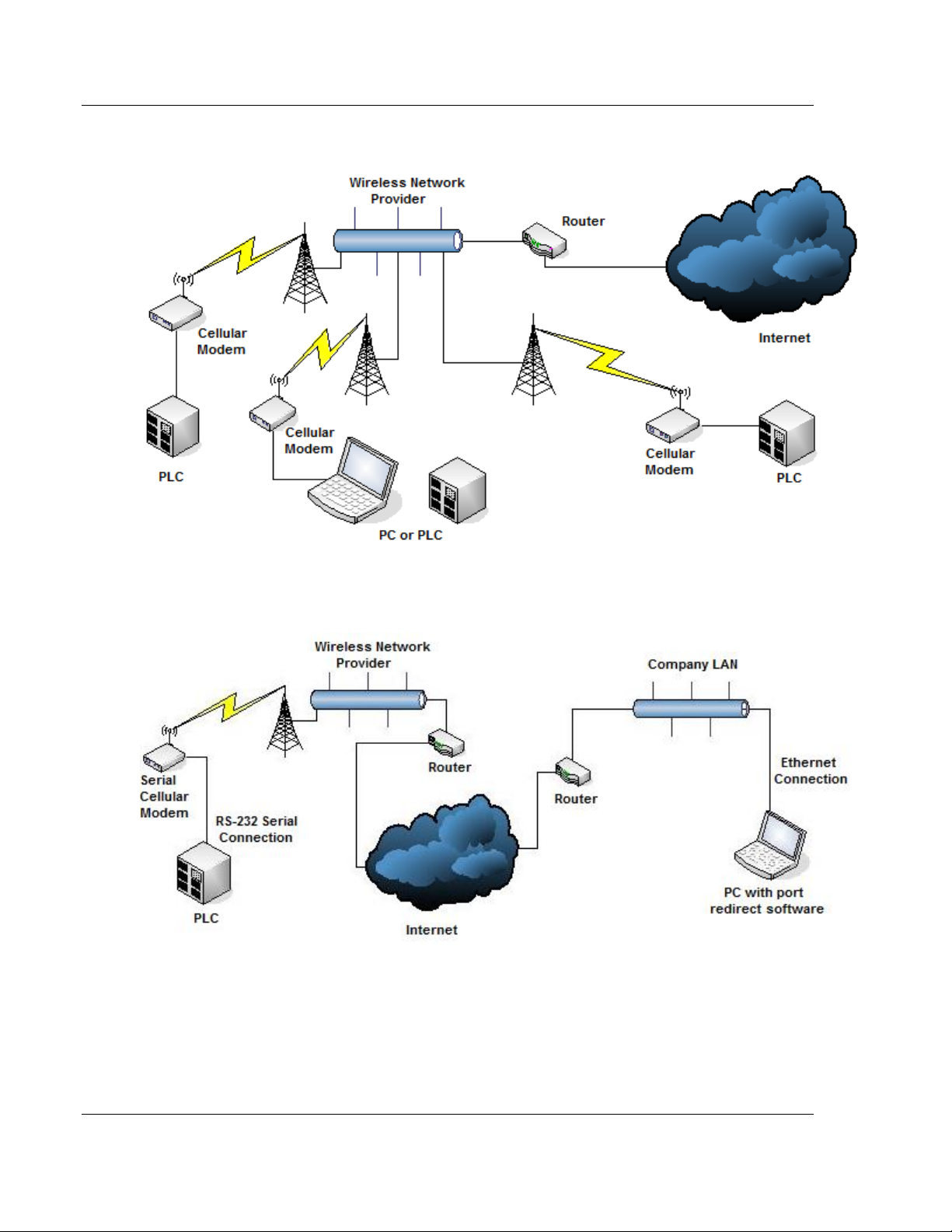
Mobile Originated to Mobile Terminated (Cellular to Cellular)
LAN to Mobile Terminated (Network to Cellular)
Page 8 of 64 ProSoft Technology, Inc.
June 22, 2015
Page 9

ICX30-HWC ♦ Industrial Cellular Gateway Start Here
Cellular Technology
CDMA, CDMA2000
GSM, UMTS/WCDMA, HSPA+, GPRS, EDGE
Bands
CDMA2000: 800/1900 MHz
GSM: 850/900/1800/1900
WCDMA: 800/850/900/1900/2100
Max Downlink Speeds
Up to 14.4 Mbps maximum (Network dependent)
Max Uplink Speeds
Up to 5.76 Mbps maximum (Network dependent)
Activation
SIM Slot (GSM), Flash Memory (CDMA)
Security
Open VPN, IPSec
GPS
GPS EtherNet/IP reporting
Enclosure
Extruded aluminum with DIN clip
Size
11.4 x 14 x 3.2 cm (W x H x D)
4.5 x 5.5 x 1.25 inches (W x H x D)
Shock
IEC 60068-2-27; 15G @ 11ms (Operational)
IEC 60068-2-27; 30G @ 18ms (Non-Operational)
Vibration
IEC 60068-2-6; 10G, 10 to 150 Hz
Ethernet Port
(1) 10/100 Base-T, RJ45 connector
Serial Port
(1) DB9 female (Serial tunneling & encapsulation)
Antenna Ports
(2) RP-SMA connector
(1) SMA Connector (GPS)
I/O Connector
Six-position screw terminal
I/O Port
(2) Discrete Inputs/Outputs (Programmable)
(2) Analog Inputs; (1) 0 to 20 mA, (1) 0 to 12 VDC
Weight
1.1 lbs (499g)
Operating Temperature
-40°F to +158°F (-40°C to +70°C)
Humidity
Up to 100% RH, with no condensation
External Power
10 to 24 VDC
Power over Ethernet
802.3af Compliant
Peak Power Consumption
< 6W
3G Cellular (M2M) User Manual
1.1.1 Specifications
Radio
Physical
Environmental
ProSoft Technology, Inc. Page 9 of 64
June 22, 2015
Page 10

Start Here ICX30-HWC ♦ Industrial Cellular Gateway
Qty.
Part Name
Part Number
Part Description
1
ICX30-HWC Cellular
Gateway
ICX30-HWC
3G 3G Cellular (M2M)
1
Antenna
AO822S-OA
2dBi Omni RP-SMA articulating
890 to 960 MHz, 1710 to 2200 MHz
1
ProSoft Solutions
DVD
DVD-001
Contains documentation for the ICX30-HWC
User Manual 3G Cellular (M2M)
1.2 Package Contents
The following components are included with the ICX30-HWC, and are required
for installation and configuration.
Important: Before beginning the installation, please verify that all of the following items are
present.
If any of these components are missing, please contact ProSoft Technology
Support for replacement parts.
1.3 System Requirements
The following system requirements are the recommended minimum
specifications to successfully install and run:
Supported operating systems:
- Microsoft Windows® Vista
- Microsoft Windows XP Professional with Service Pack 1 or 2
- Microsoft Windows 7 Professional (32-or 64-bit)
- Microsoft Windows 2000 Professional with Service Pack 1, 2, or 3
- Microsoft Windows Server 2003
Pentium® II 450 MHz minimum. Pentium III 733 MHz (or better)
128 Mbytes of RAM minimum, 256 Mbytes of RAM recommended
100 Mbytes of free hard disk space (or more based on application
requirements)
256-color VGA graphics adapter, 800 x 600 minimum resolution (True Color
1024 x 768 recommended)
DVD drive
Ethernet hub with standard RJ45 Ethernet cable
or
Ethernet port with RJ45 crossover cable for direct connection to module
In addition, you will need:
A connection to an existing wired or wireless Ethernet network, with a Static
or Dynamic IP address for your computer
Static IP address, Subnet Mask and Gateway address for each device you
plan to install. Obtain this information from your system administrator.
Page 10 of 64 ProSoft Technology, Inc.
June 22, 2015
Page 11
ICX30-HWC ♦ Industrial Cellular Gateway Start Here
3G Cellular (M2M) User Manual
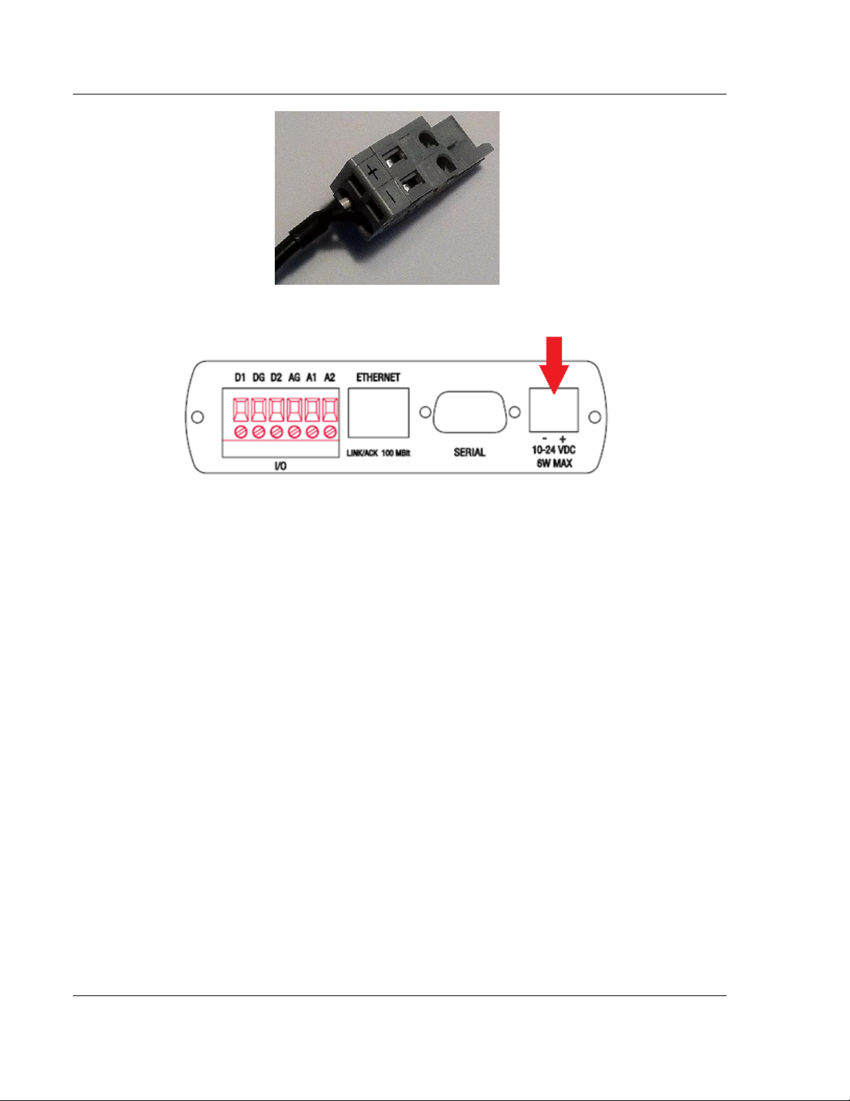
1.4 Power Requirements
The ICX30-HWC accepts voltages between 10 and 24 VDC (300 mA @ 12 VDC,
150 mA @ 24 VDC), with an average power draw of 6 watts or less. A
detachable power connector comes with the radio, as shown below. The
connector terminals are labeled + (positive DC connection) and - (DC ground
connection).
The AC-to-DC power supply adapter may be used. DC power wires must be less
than 2 meters in length to meet regulatory requirements.
Important: When wiring the power connector, be sure to observe the proper polarity markings on
the power connector. Improper connector wiring can cause serious damage to the ICX30-HWC
which will not be covered under the ProSoft Warranty.
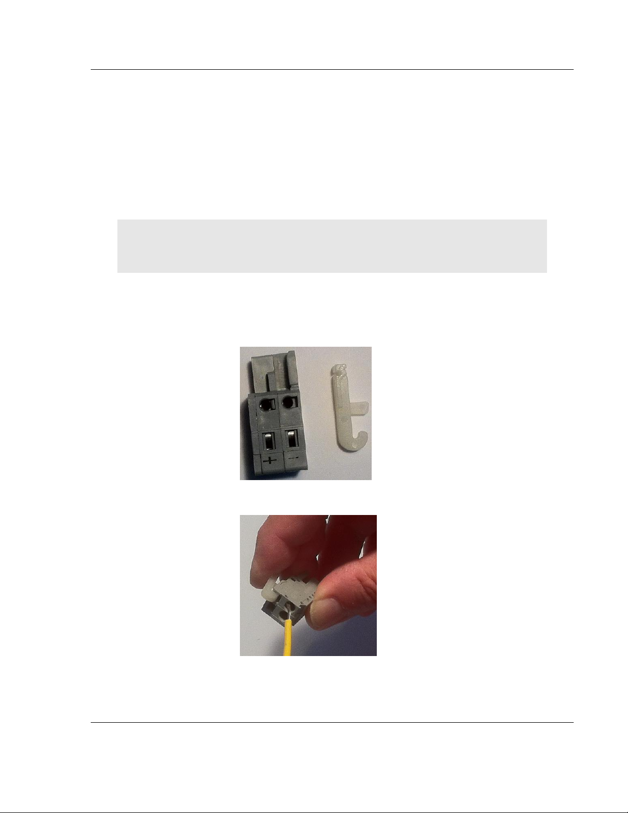
The power connector (ProSoft P/N 002-0116) and wire installation tool (ProSoft
P/N 357-0061) are shown in the following graphic. The wire installation tool is
helpful when installing wires into the spring-loaded contacts inside the power
connector.
1 To use the wire installation tool, insert it into the connector as shown.
2 Press down on the installation tool to use it as a level which opens the
connector's contacts to insert a wire. A properly wired connector is shown.
ProSoft Technology, Inc. Page 11 of 64
June 22, 2015
Page 12
Start Here ICX30-HWC ♦ Industrial Cellular Gateway
User Manual 3G Cellular (M2M)
3 Insert the connector into the power port on the bottom of the ICX30-HWC.
Page 12 of 64 ProSoft Technology, Inc.
June 22, 2015
Page 13

ICX30-HWC ♦ Industrial Cellular Gateway Configuration Webpage
In This Chapter
Configuration Webpage Setup .............................................................. 14
Assigning an IP Address to the ICX30-HWC ......................................... 15
Connecting to your Cellular Provider ..................................................... 17
Configuration Webpage ......................................................................... 21
3G Cellular (M2M) User Manual
2 Configuration Webpage
The configuration webpage is used to configure and manage the ICX30-HWC.
First-time setup must be performed over a wired network, where provider-specific
cellular configuration details are configured. Once initially setup, you can access
the webserver over the LAN and cellular networks (unless LAN access is
disabled).
Key benefits of the web based configurator include:
Login and configure device parameters
Adjust network settings
Change security settings
Update events reporting
Update firmware
ProSoft Technology, Inc. Page 13 of 64
June 22, 2015
Page 14
Configuration Webpage ICX30-HWC ♦ Industrial Cellular Gateway
User Manual 3G Cellular (M2M)
2.1 Configuration Webpage Setup
1 The default IP address of the ICX30-HWC is 192.168.0.250. If your PC is on
a different subnet, temporarily set the IP address of your PC to 192.168.0.xxx
with a subnet of 255.255.255.0.
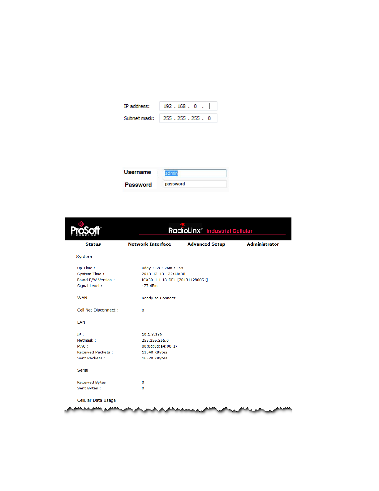
2 Open a web browser and enter the ICX30-HWC default address of
http://192.168.0.250:8080
3 Once the ICX30-HWC homepage opens, enter the USERNAME and
PASSWORD to log in. You will be able to customize these later.
4 The default USERNAME is 'admin' and the default PASSWORD is 'password'.
5 After successful login, the homepage displays data from the Status tab.
Page 14 of 64 ProSoft Technology, Inc.
June 22, 2015
Page 15
ICX30-HWC ♦ Industrial Cellular Gateway Configuration Webpage
3G Cellular (M2M) User Manual
2.2 Assigning an IP Address to the ICX30-HWC
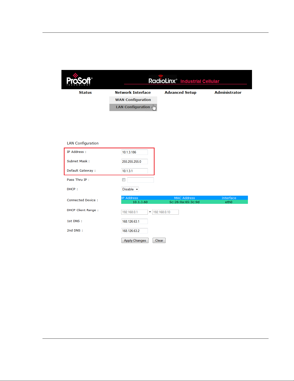
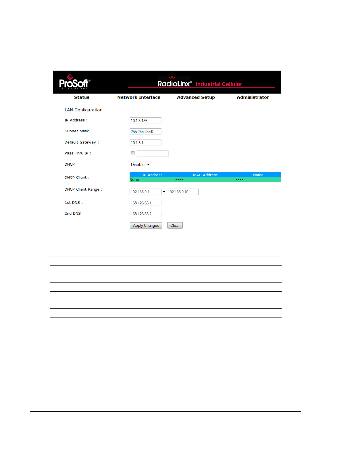
1 Mouse over the Network Interface heading and choose LAN CONFIGURATION.
2 Enter the IP ADDRESS, SUBNET MASK, and DEFAULT GATEWAY to be assigned
to the ICX30-HWC. You will not need to edit the rest of the parameters at this
time.
ProSoft Technology, Inc. Page 15 of 64
June 22, 2015
Page 16
Configuration Webpage ICX30-HWC ♦ Industrial Cellular Gateway
User Manual 3G Cellular (M2M)
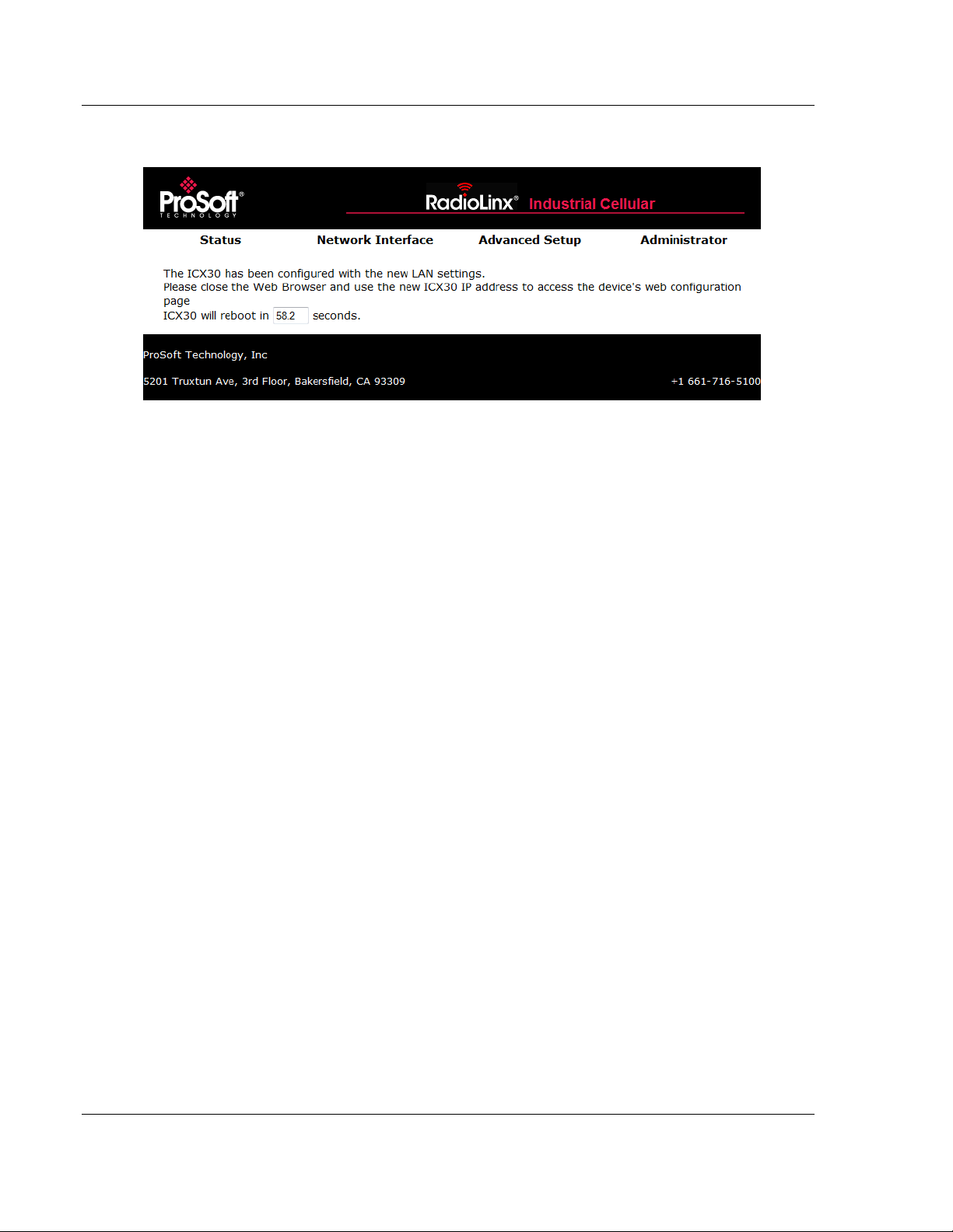
3 Click APPLY CHANGES. The ICX30-HWC will automatically reboot.
4 Once the reboot is complete, reset your PC back to its original IP address.
This IP address should now be on the same subnet as the ICX30-HWC.
5 Close your browser and open a new session. Enter the new IP address of the
ICX30-HWC to access the configuration webpage.
Page 16 of 64 ProSoft Technology, Inc.
June 22, 2015
Page 17
ICX30-HWC ♦ Industrial Cellular Gateway Configuration Webpage
3G Cellular (M2M) User Manual
2.3 Connecting to your Cellular Provider
The ICX30-HWC supports 3G GSM/GPRS and CDMA (where applicable)
networks. It uses your cellular provider as an ISP (Internet Service Provider) to
connect you to the Internet.
Cellular devices using GSM technology, such as AT&T, require a SIM
(Subscriber Identity Module) card to be installed in the radio.
Cellular devices using CDMA technology, such as Verizon, do not require a
SIM card.
2.3.1 Steps of a connection using GSM/GPRS
The Subscriber Identity Module (SIM) in the ICX30-HWC is a smartcard that
securely stores the key identifying a cellular subscriber. Generally, you will only
need to install a SIM once in the life of the cellular gateway, and it may be preinstalled by your ProSoft Technology Representative.
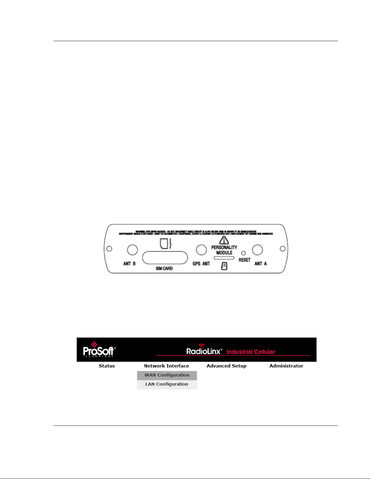
The SIM card slot is located on the front of the cellular gateway.
1 Insert the SIM card into the ICX30-HWC and cycle power. The SIM card is
read by the ICX30-HWC upon boot up.
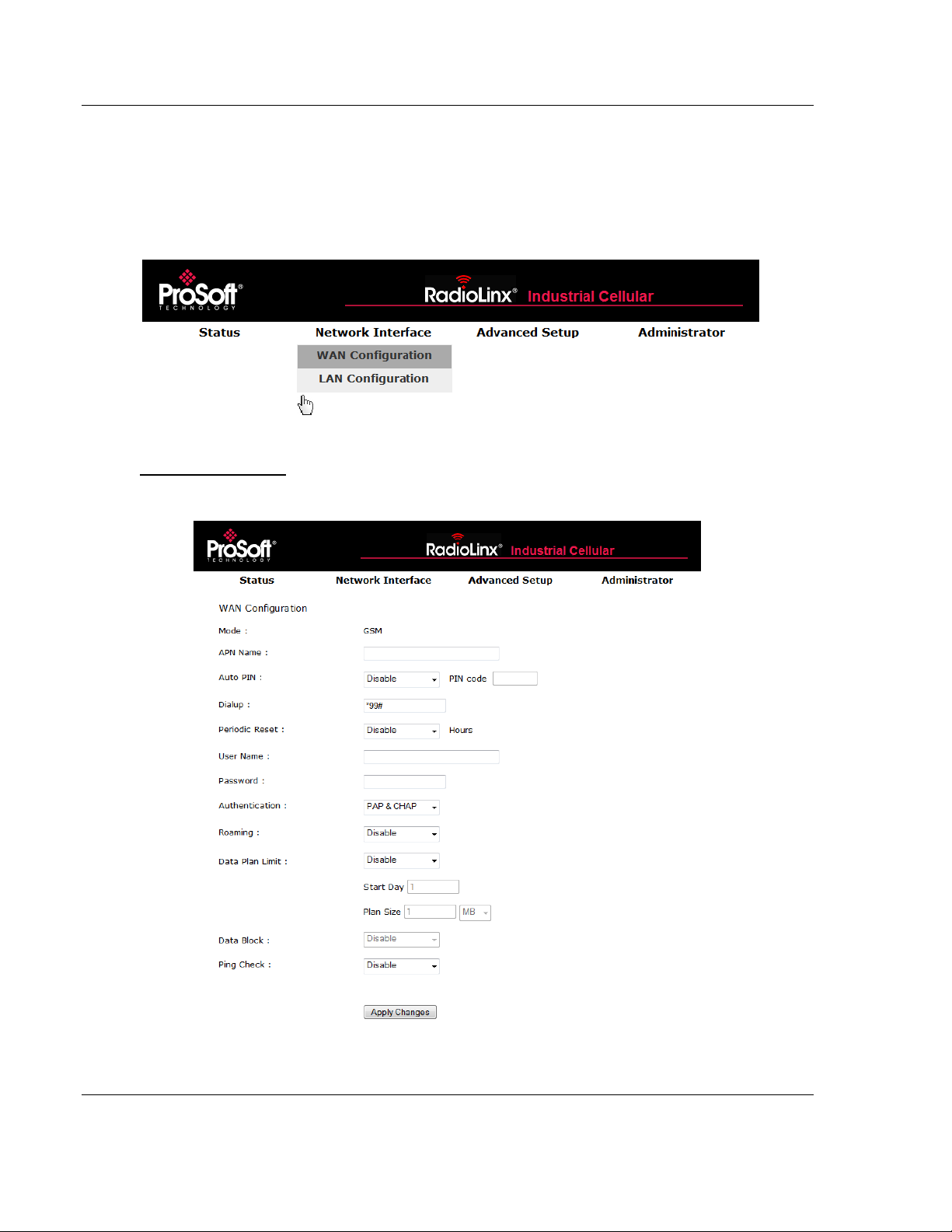
2 Open the Network Interface > WAN Configuration webpage.
ProSoft Technology, Inc. Page 17 of 64
June 22, 2015
Page 18
Configuration Webpage ICX30-HWC ♦ Industrial Cellular Gateway
User Manual 3G Cellular (M2M)
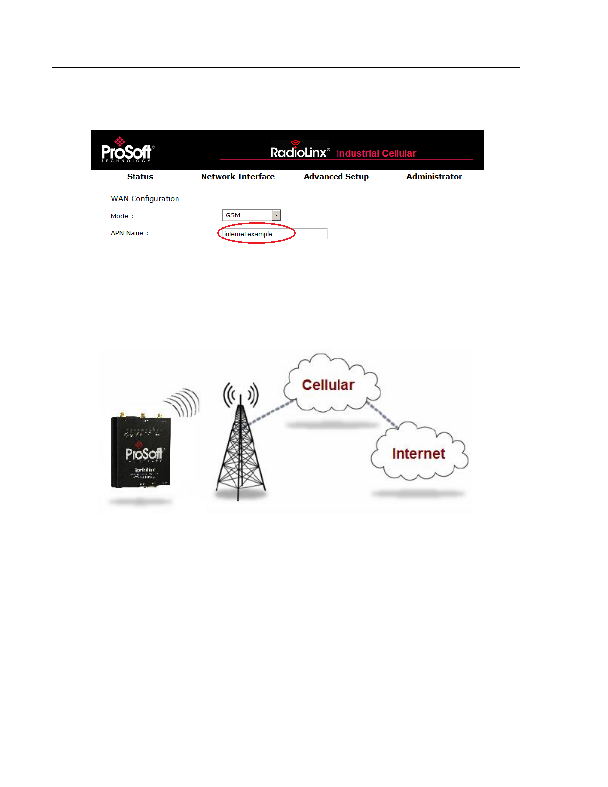
3 Enter the Access Point Name (APN) information in the APN NAME field. This
information is provided from your cellular provider. Click APPLY CHANGES.
The ICX30-HWC will reboot.
4 After the ICX30-HWC reboots, it establishes a PPP (Point to Point Protocol or
"dial" up connection) link to your cellular provider network, also called
registering on the network, and receives an IP address.
5 When the ICX30-HWC has received its IP address from your cellular
provider, a connection to the Internet or the cellular network is also available
for computers or other devices to connect directly to the ICX30-HWC.
Page 18 of 64 ProSoft Technology, Inc.
June 22, 2015
Page 19
ICX30-HWC ♦ Industrial Cellular Gateway Configuration Webpage
3G Cellular (M2M) User Manual
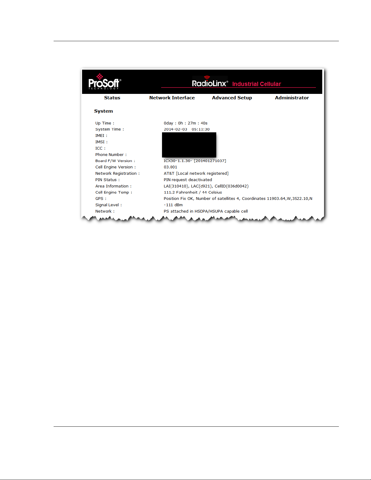
6 The GSM network information is now displayed on the Status web page.
ProSoft Technology, Inc. Page 19 of 64
June 22, 2015
Page 20
Configuration Webpage ICX30-HWC ♦ Industrial Cellular Gateway
User Manual 3G Cellular (M2M)
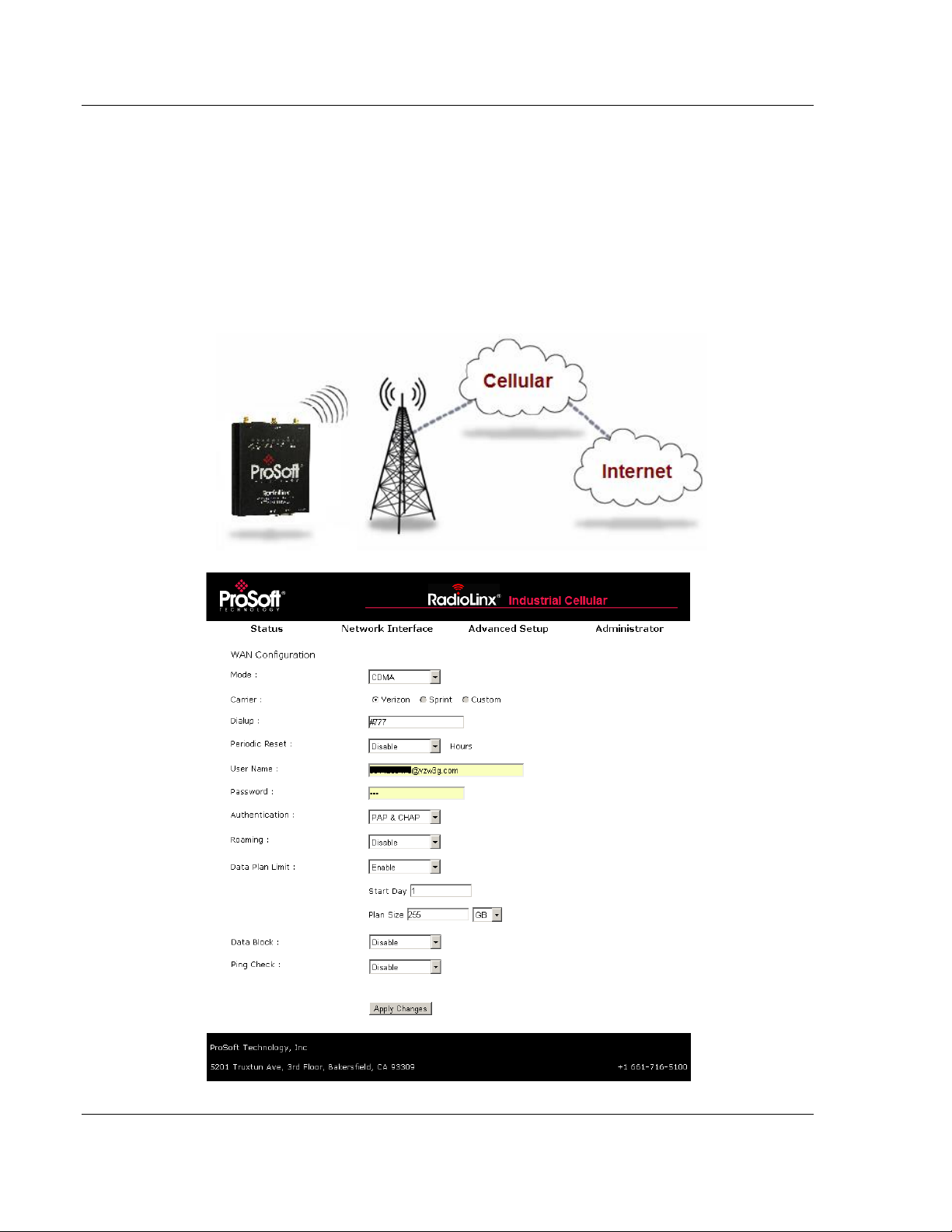
2.3.2 Steps of a connection using CDMA (where applicable):
1 When your ICX30-HWC is powered on, it automatically searches for cellular
service using CDMA-based cellular technology.
2 Your ICX30-HWC establishes a PPP (Point-to-Point Protocol or "dial" up
connection) link to the Verizon network, also called registering on the
network, and receives an IP address.
3 When your ICX30-HWC has received its IP address from your cellular
provider, a connection to the Internet or the cellular network is also available
for computers or other devices to connect directly to the ICX30-HWC.
Page 20 of 64 ProSoft Technology, Inc.
June 22, 2015
Page 21

ICX30-HWC ♦ Industrial Cellular Gateway Configuration Webpage
3G Cellular (M2M) User Manual
2.4 Configuration Webpage
There are four main headings of the configuration webpage:
Status
Network Interface
Advanced Setup
Administrator
Mouse over each heading to reveal additional sub-headings.
ProSoft Technology, Inc. Page 21 of 64
June 22, 2015
Page 22

Configuration Webpage ICX30-HWC ♦ Industrial Cellular Gateway
User Manual 3G Cellular (M2M)
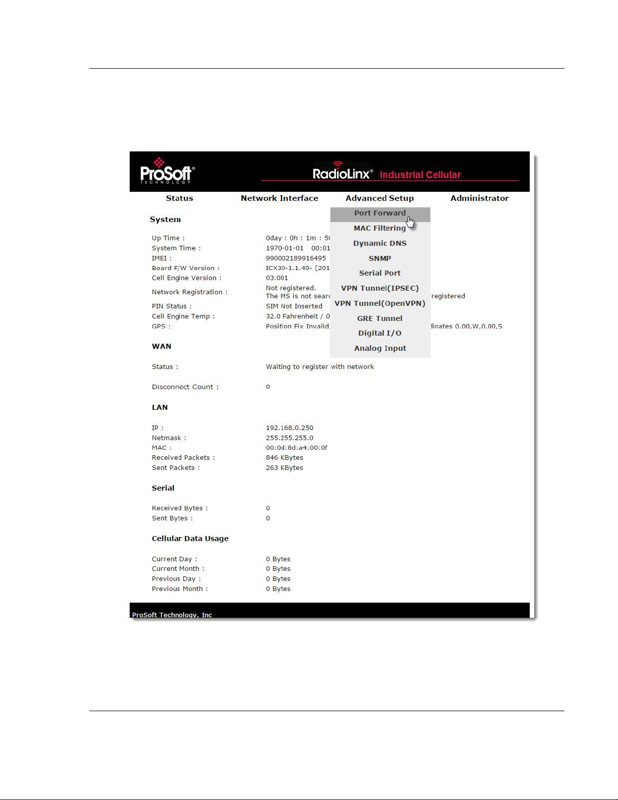
2.4.1 Status
The Status web page displays the current settings of the cellular gateway
including up time, IP address, and cellular data usage.
Page 22 of 64 ProSoft Technology, Inc.
June 22, 2015
Page 23

ICX30-HWC ♦ Industrial Cellular Gateway Configuration Webpage
System
Description
Up Time
Amount of time the ICX30-HWC has been active since the last power
cycle or a reset
System Time
Current date and time of the ICX30-HWC
IMEI
International Mobile Station Equipment Identity number
IMSI
International Mobile Subscriber Identity number
ICC
Integrated Circuit Card identifier - Unique to each SIM card
Phone Number
Phone number assigned to the SIM card
Board F/W Version
Firmware version of the cellular hardware
Cell Engine Version
Version of cellular engine processor
MEID (CDMA only)
Mobile equipment identifier number; unique CDMA equipment
Network Registration
Registered local cellular network
PIN Status
PIN request activated/deactivated
Area Information
LAI = Local Area Identity
LAC = Location Area Code
CellID = Cellular ID
Cell Engine Temp
Temperature of cellular engine processor
GPS
Position Fix: Invalid, OK
Number of Satellites: 0 to 10
Coordinates: Longitude and Latitude
Signal Level
Signal level of cellular network (dBm)
Network
Type of cellular technology in use (Example: HSUPA for GSM)
WAN
Status
Status of cellular network connection
IP
IP Address of the ICX30-HWC on the WAN
Sent Packets
Total number of sent packets on the WAN
Received Packets
Total number of received packets on the WAN
Link Time
Number of days, hours, minutes, seconds connected to the WAN
Disconnect Count
Number of disconnects from the WAN
LAN IP
IP Address of the ICX30-HWC on the LAN
Netmask
Subnet mask
MAC
MAC address
Received Packets
Total number of received packets on the LAN
Sent Packets
Total number of sent packets on the LAN
Serial
Received Bytes
Total number of bytes received on the serial port
Sent Bytes
Total number of bytes sent from the serial port
Cellular Data Usage
Current Day
Number of bytes received and sent in the current day
Current Month
Number of bytes received and sent in the current month
Previous Day
Number of bytes received and sent from the previous day
Previous Month
Number of bytes received and sent from the previous month
3G Cellular (M2M) User Manual
ProSoft Technology, Inc. Page 23 of 64
June 22, 2015
Page 24
ICX30-HWC ♦ Industrial Cellular Gateway Configuration Webpage
3G Cellular (M2M) User Manual
2.4.2 Network Interface
The Network Interface tab allows you to configure the WAN (Wide Area Network)
and LAN (Local Area Network) of the ICX30-HWC.
WAN Configuration
ICX30-HWC WAN configuration.
ProSoft Technology, Inc. Page 24 of 64
June 22, 2015
Page 25

ICX30-HWC ♦ Industrial Cellular Gateway Configuration Webpage
WAN Configuration
Description
Mode
GSM or CDMA
APN Name
Access point name provided by the carrier
Auto PIN
Enable or Disable
PIN Code
(Optional) PIN code to unlock SIM card
Carrier (CDMA only)
Verizon, Sprint, Custom
Dialup
Sequence to dial to establish a connection.
This field cannot be left blank when you APPLY
CHANGES. It will re-populate with a carrierassigned value upon reboot.
Periodic Reset
Power cycle every X number of hours
User Name
(Optional) User name for connection assigned
by the carrier upon reboot.
Password
(Optional) Password for connection assigned
by the carrier upon reboot.
Authentication
PAP - Password Authentication Protocol
CHAP - Challenge Handshake Authentication
Protocol
PAP & CHAP - Both are used
Roaming
Helps ensure a mobile ICX30-HWC stays
connected
Data Plan Limit
Enable or Disable
Start Day
Starting day of billing of each month
Plan Size
With Data Block enabled, the maximum
number of megabytes (MB) or gigabytes (GB)
of 3G data usage before 3G communications
are shut down until the next Start Day.
Data Block
Enable or Disable
Ping Check
Allows pinging two servers at set intervals. If
fail count is reached on both servers, the
ICX30-HWC disconnects from the WAN and
cycles power.
Interval
Trial interval time in seconds
Fail Count
Maximum number of ping failures before reset
1st Server
IP address of the 1st server to ping
2nd Server
IP address of the 2nd server to ping
3G Cellular (M2M) User Manual
ProSoft Technology, Inc. Page 25 of 64
June 22, 2015
Page 26
Configuration Webpage ICX30-HWC ♦ Industrial Cellular Gateway
LAN Configuration
Description
IP Address
IP address of the ICX30-HWC on the LAN
Subnet Mask
Subnet mask of the ICX30-HWC on the LAN
Default Gateway
Gateway of the ICX30-HWC on the LAN
Pass Thru IP
IP address on the LAN to connect to through the ICX30-HWC
DHCP
Enable or Disable DHCP server of the ICX30-HWC
DHCP Client Range
IP address range for DHCP server
1st DNS
First domain name server IP address
2nd DNS
Second domain name server IP address
User Manual 3G Cellular (M2M)
LAN Configuration
ICX30-HWC LAN configuration.
Page 26 of 64 ProSoft Technology, Inc.
June 22, 2015
Page 27
ICX30-HWC ♦ Industrial Cellular Gateway Configuration Webpage
3G Cellular (M2M) User Manual
2.4.3 Advanced Setup
The Advanced Setup tab includes the setup for port forwarding, serial port, digital
I/O, and analog input ports.
ProSoft Technology, Inc. Page 27 of 64
June 22, 2015
Page 28

Configuration Webpage ICX30-HWC ♦ Industrial Cellular Gateway
Port Forwarding
Description
IP Address
Redirect IP address: Target device IP address on the LAN
WAN Port
WAN port number range (1 to 65535)
LAN Port
LAN port number range (1 to 65535)
MAC Filtering
Description
MAC Address
MAC address of the device allowed to connect to the internet
Dynamic DNS
Description
Service Provider/Server
DDNS service web page
Domain Name
Sets the DDNS host name or alias from DDNS server
User Name/Email
User name to log into the DDNS server
Password/Key
Password to log into the DDNS server
SNMP
Description
Activate
Enable or disable SNMP manager
System Name
System name of SNMP network
System Contact
Email address of SNMP network administrator
Write Community Name
Private: Write community string disabled (default)
Public: Write community string enabled
User Manual 3G Cellular (M2M)
Port Forward
Port forwarding allows a remote computer or device to access a device on the
ICX30-HWC LAN.
Note: There is a limit of nine (9) entries in the Port Forwarding table.
MAC Filtering
Entries in this table are used to restrict certain types of data packets from your
local network to the Internet through the ICX30-HWC. These filters can be helpful
in securing or restricting access to your local network.
Dynamic DNS
Dynamic DNS (DDNS) is a method of mapping IP addresses that are assigned to
a domain name.
SNMP
Simple Network Management Protocol (SNMP) is a set of protocols for managing
a network. It is used to configure and collect information from network devices.
Page 28 of 64 ProSoft Technology, Inc.
June 22, 2015
Page 29

ICX30-HWC ♦ Industrial Cellular Gateway Configuration Webpage
SNMP
Description
Read Community Name
Private: Read community string disabled
Public: Read community string enabled (default)
1st Trap Server IP
IP address of the 1st trap server. The ICX30-HWC will report the
trap message this IP address
2nd Trap Server IP
IP address of the 2nd trap server. The ICX30-HWC will report the
trap message this IP address
3rd Trap Server IP
IP address of the 3rd trap server. The ICX30-HWC will report the
trap message this IP address
SNMPv3
Use SNMP version 3 reporting and features
Serial Port
Description
Baud Rate
Baud rate used on the ICX30-HWC serial port
Data
Data bits
Parity
Parity
Stop
Stop bits
Flow Control
Flow control enable or disable
Characters Timeout
Number of characters the ICX30-HWC will wait until a timeout is
determined from the device connected to the serial port.
Mode
Disable, Modbus Point-To-Point, Modbus Point-To-Multipoint, DF1
(see below)
Modbus Point-To-Point
Description
Server/Client
Server = ICX30-HWC serial port is connected to a Modbus slave
Client = ICX30-HWC serial port is connected to a Modbus master
Remote ICX30 Server IP
Address
(Client mode only) IP address of remote ICX30-HWC that is
connected to the Modbus slave.
3G Cellular (M2M) User Manual
Serial Port
The RS-232 serial port supports the Modbus and DF1 industrial communication
protocols. For either protocol, a master or slave(s) can be connected to the
ICX30-HWC serial port.
ProSoft Technology, Inc. Page 29 of 64
June 22, 2015
Page 30

Configuration Webpage ICX30-HWC ♦ Industrial Cellular Gateway
Modbus Point-To-Multipoint
Description
Server/Client
Server = ICX30-HWC serial port is connected
to one or more Modbus slaves
Client = ICX30-HWC serial port is connected
to a Modbus master
TCP/IP Protocol
UDP
Remote ICX30 Server IP
Address
(Server mode only) WAN IP address of
Modbus master radio
Port
Modbus service port, usually 502
Listen Port No.
(Client mode only) Defines the Modbus
service port to listen to
Modbus
RTU or ASCII
Add Address
Mapping
(Client mode only) WAN IP address of
Modbus slave radio
Start ID
(Client mode only) Slave ID start
End ID
(Client mode only) Slave ID end
DF1 Description
ICX30 Serial Port
Master/Slave
Master = ICX30-HWC serial port is connected
to a DF1 master
Slave = ICX30-HWC serial port is connected
to one or more DF1 slaves
Listen Port Number
(Master mode only) Defines which DF1
service port to listen to
Add Remote ICX30
Address
(Master mode only) IP address of a remote
ICX30 connected to a DF1 slave
Slave ID
(Master mode only) DF1 slave ID of remote
DF1 slave
Remote ICX30 Master IP
Address
(Slave mode only) IP address of remote
ICX30 connected to a DF1 master
Port
(Slave mode only) Service port of remote
ICX30 connected to a DF1 master
User Manual 3G Cellular (M2M)
Page 30 of 64 ProSoft Technology, Inc.
June 22, 2015
Page 31

ICX30-HWC ♦ Industrial Cellular Gateway Configuration Webpage
VPN Tunnel (IPSEC)
Description
Gateway/Client
Disable, Client, or Gateway
Local Group
(Client mode) ICX30-HWC connects to a remote VPN server.
LAN Subnet + USER FQDN, LAN Subnet + FQDN
(Gateway mode) ICX30-HWC acts as a VPN server. IP +
LAN Subnet
Local Group FQDN (User FQDN)
(Client mode only) Local group Fully Qualified Domain
Name (FQDN) is user-defined. Ex. User_test1
Remote Group
(Client mode) IP + LAN Subnet
(Gateway mode) Dynamic IP + USER FQDN, Dynamic IP +
FQDN
Remote IP
(Client mode only) WAN IP address of gateway/ICX30-HWC
Remote Group IP
LAN IP address of gateway/ICX30-HWC. Only the first two
octets are needed. Ex. XXX.YYY.0.0
Remote Group Subnet
255.255.255.0
Remote Group FQDN
(Gateway mode only) Remote group Fully Qualified Domain
Name (FQDN) is user-defined. Ex. User_test1
Aggressive Mode
On
Pre-Shared Key
Key to connect in either mode
Phase 1 and 2 DH Group
MODP1024 or MODP1536
Phase 1 Encryption
DES, 3DES, AES192, or AES256
Phase 1 Authentication
MD5 or SHA1
Phase 2 Encryption
DES, 3DES, AES192, or AES256
Phase 2 Authentication
MD5 or SHA1
VPN Tunnel (OpenVPN)
Description
Server/Client
Disable or Client
Interface Type
Network Tunnel (TUN)
Protocol
TCP or UDP
Authorization
Disable Transport Layer Security (TLS) authorization
Encryption Cipher
None, Use Default, AES-128-CBC, AES-192-CBC, or AES-256-CBC
TLS Renegotiation Time
Transport Layer Security renegotiation time in seconds
LZO Compression
Disabled, None, Enabled, Adaptive
3G Cellular (M2M) User Manual
VPN Tunnel (IPSEC)
VPN Tunnel Internet Protocol Security (IPSEC). It consists of protocol(s) used for
authentication and encryption.
VPN Tunnel (Open VPN)
The Virtual Private Network (VPN) Tunnel allows you to access a private local
network through the ICX30-HWC. The DHCP (LAN) must be enabled when using
the VPN Tunnel.
ProSoft Technology, Inc. Page 31 of 64
June 22, 2015
Page 32

Configuration Webpage ICX30-HWC ♦ Industrial Cellular Gateway
VPN Tunnel (OpenVPN)
Description
Port
Service port number of the VPN server
Server Address
IP address of the VPN server
Custom Configuration
Optional configuration file for the VPN
Certificate Authority
VPN authentication that issues certificates for VPN, Secure Internal
Communication (SIC), and users
Client Certificate
Issued by a certificate authority as proof of identity
Client Key
Password to corresponding client certificate
User Manual 3G Cellular (M2M)
GRE Tunnel
GRE tunneling provides full connectivity between two sites without using
encryption. GRE tunneling supports multiple routes and multiple endpoints over a
single GRE tunnel.
Page 32 of 64 ProSoft Technology, Inc.
June 22, 2015
Page 33

ICX30-HWC ♦ Industrial Cellular Gateway Configuration Webpage
GRE Tunnel
Description
Runt
Enable or Disable GRE Tunnel
Tunnel Destination Address
Enter the Tunnel Destination Address.
Tunnel TTL
TIme a packet can remain on the network before being discarded.
Routing
Alows the configuration of multiple routes (optional).
IP Group
Enter a specific IP Group
Netmask
Enter a Netmask for the IP group.
Add Entry button
Adds the IP Group and Netmask to the Routing table
Delete Entry button
Deletes selected entries from the Routing table
Apply Changes button
Click when you are satisfied with your GRE Tunnel settings
Reset button
Resets all fields back to empty values.
3G Cellular (M2M) User Manual
New configurations are saved on a micro SD card if inserted allowing modem
reboot or configuration transfer via micro SD to another radio without loss of
configuration data/fields.
ProSoft Technology, Inc. Page 33 of 64
June 22, 2015
Page 34

Configuration Webpage ICX30-HWC ♦ Industrial Cellular Gateway
Digital I/O
Description
No. 1
Input or Output
SMS Alarm Entry 1
Phone number 1 to send SMS text alarm
SMS Alarm Entry 2
Phone number 2 to send SMS text alarm
SMS Alarm Entry 3
Phone number 3 to send SMS text alarm
SMS Alarm Entry 4
Phone number 4 to send SMS text alarm
SMS Alarm Entry 5
Phone number 5 to send SMS text alarm
SMS Alarm Text
(Input only)
Low
Text of alarm to be sent to phone number(s) when
status changes from High to Low
High
Text of alarm to be sent to phone number(s) when
status changes from Low to High
No. 2
Input or Output
Toggle Output
(Output only)
Status
Digital No1 [OFF], Digital No2 [Open Drain]
Digital No1 [OFF], Digital No2 [NULL]
Analog Input
Description
Scan Rate
(250 to 10000 ms)
Channel 1
Voltage: 0 ~ 12 V
Channel 2
Current: 0 ~ 20 mA @ 2.2 V
Status
RAW Ain0: Raw analog input value for channel 1 (A1)
RAW Ain1: Raw analog input value for channel 2 (A2)
User Manual 3G Cellular (M2M)
Digital I/O
There are two digital input/output terminals on the ICX30-HWC. SMS text
messages can be sent to up to five phone numbers upon the status change of a
digital input.
Analog Input
There are two analog input channels for measuring voltage levels.
Page 34 of 64 ProSoft Technology, Inc.
June 22, 2015
Page 35

ICX30-HWC ♦ Industrial Cellular Gateway Configuration Webpage
Password
Description
Current Name
Current login user name
Current Password
Current login password
New Name
New login user name
New Password
New login password
Confirm Password
Re-enter the new login password
NTP
Description
Current Time
Current Year, Month, Day, Hour, Minute, Second
Enable
Enables NTP client update with an NTP server
NTP Server
Address of NTP server
Time Zone
Local time zone of the ICX30-HWC
3G Cellular (M2M) User Manual
2.4.4 Administrator
The Administrator tab allows you to configure the password, record logs, update
firmware, etc.
Password
Configure and edit the user name and password to access the configuration web
page here.
NTP
The Network Time Protocol (NTP) is used for clock synchronization between
your ICX30-HWC and an NTP server.
ProSoft Technology, Inc. Page 35 of 64
June 22, 2015
Page 36

Configuration Webpage ICX30-HWC ♦ Industrial Cellular Gateway
Ping
Description
IP Address/Host Name
WAN IP address or host name to be pinged
Backup (Save/Reload)
Description
Save Settings to File
Saves configuration to a file
Load Settings from File
Browse for the selected configuration file and click UPLOAD
Restore to Factory Default
Restores to ICX30-HWC factory default
Logs
Description
Enable Logs
System logs enabled for review
General
Description
Web Access
Web access via HTTPS or HTTP, and Port Number
HTTP Access on WAN
Allows or blocks web page access from the WAN
NAT
Enable or disable network address translation
Upgrade
Description
Select File
BROWSE and select the firmware file and click UPGRADE
User Manual 3G Cellular (M2M)
Ping
You can ping a remote device to determine whether you can connect to it.
Backup
The configuration of the ICX30-HWC can be saved to a file for backup. The file
can also be loaded back into the ICX30-HWC. Restoring to factory default can be
done here as well as pressing and holding the RESET button on the top of the
radio.
Logs
Record system logs of ICX30-HWC activity for analysis.
General
Adjust the settings to access the configuration web page here.
Firmware Update
Upgrade the ICX30-HWC firmware here.
Page 36 of 64 ProSoft Technology, Inc.
June 22, 2015
Page 37

ICX30-HWC ♦ Industrial Cellular Gateway Hardware Installation
In This Chapter
Antenna Installation ............................................................................... 37
Connecting the Radio to a Network Device ........................................... 38
LED Indicators ....................................................................................... 42
3G Cellular (M2M) User Manual
3 Hardware Installation
The ICX30-HWC should be mounted in a position that allows easy access for the
cables so they are not bent, constricted, in close proximity to high amperage, or
exposed to extreme temperatures. The LEDs on the front panel should be visible
for ease of operational verification. You should ensure that there is adequate
airflow around the device but kept free from direct exposure to the elements,
such as sun, rain, dust, and so on.
Caution: The ICX30-HWC is in a hardened case, and designed for use in industrial and extreme
environments. However, unless you are using cables expressly designed for such environments,
they can fail if exposed to the same conditions the ICX30-HWC can withstand.
3.1 Antenna Installation
Antennas selected should not exceed a maximum gain of 5 dBi under standard
installation configuration. In more complex installations (such as those requiring
long lengths of cable, and/or multiple connections), it is imperative that the
installer follow maximum dBi gain guidelines in accordance with the radio
communications regulations of the Federal Communications Commission (FCC),
Industry Canada, or your country's regulatory body (if used outside the US).
Your ICX30-HWC will work with most quad-band GSM cellular antennas with a
SMA connector. Connect the primary antenna or primary RF cable directly to the
'ANT A' antenna connector on the front of the ICX30-HWC.
A secondary antenna port labeled 'ANT B' is provided to attach an additional
antenna. Use of a secondary antenna is not required, but will often increase
cellular reliability and throughput performance.
This device is not intended for use within close proximity of the human body.
Antenna installation should have at least 20 cm separation from the operator.
Tip: When using a cable to an antenna placed away from the modem, minimize the length of your
cable. All gain from a more advantageous antenna placement can be lost with a long cable to the
modem.
ProSoft Technology, Inc. Page 37 of 64
June 22, 2015
Page 38
Hardware Installation ICX30-HWC ♦ Industrial Cellular Gateway
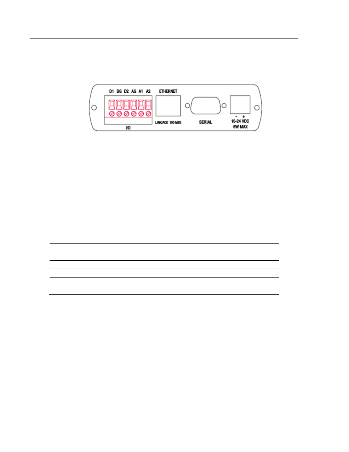
Terminal
Description
D1
Digital terminal 1 can be configured as Input or Output
DG
Digital signal ground
D2
Digital terminal 2 can be configured as Input or Output
AG
Analog signal ground
A1
Analog input 1 voltage (0 ~ 12 V)
A2
Analog input 2 current (0 ~ 20 mA @ 2.2 V)
User Manual 3G Cellular (M2M)
3.2 Connecting the Radio to a Network Device
The application ports are located on the bottom of the radio.
The I/O port uses (2) Discrete Inputs/Outputs and (1) Analog Input
The Ethernet port uses a standard RJ45 connector
The serial port uses a standard DB9 connector for RS-232 connectivity
3.2.1 I/O Terminal
There are two digital input/output and two analog terminals on the ICX30-HWC.
An SMS text message can be configured and sent to your phone upon change of
the digital input(s). (See Configuration Webpage)
Page 38 of 64 ProSoft Technology, Inc.
June 22, 2015
Page 39

ICX30-HWC ♦ Industrial Cellular Gateway Hardware Installation
Terminal
Description
Digital input voltage
-5 ~ 20 V (on input mode)
Digital output sinking current
300 mA
Analog input (CH1) voltage
-0.5 ~ 3.5 V
Analog input (CH2) voltage
-1.5 ~ 18 V
Digital I/O
Description
Operating input voltage range
-1 ~ 6 V (continuous)
Operating input voltage range
-1 ~ 15 V (within 1ms)
Input impedance
>1 KOhm
Operating output sinking current max
50 mA (continuous)
Operating output sinking current max
200 mA (within 1ms)
Output impedance
<30 Ohm
Output type
Open-drain
Analog Input
Description
CH1 Input impedance
110 Ohm//0.1 uF
CH1 Input current
0 ~ 20 mA
CH1 Input voltage
0 ~ 2.2 V
CH2 Input impedance
49 KOhm//0.1 uF
CH2 Input voltage
0 ~ 10 V
Isolation Voltage
Description
Voltage among any Power pins, RJ-45 Ethernet
pins, AGND or DGND
> 500 V
Voltage between AGND to DGND
> 1 KV
Voltage between Power pins to AGND or DGND
> 1 KV
3G Cellular (M2M) User Manual
Electrical Specification of I/O Terminals
Limiting Values - (Outside of limiting value may damage hardware permanently,
even for a short duration)
Digital I/O
Analog Inputs (12 AD input)
Isolation Voltages
ProSoft Technology, Inc. Page 39 of 64
June 22, 2015
Page 40

Hardware Installation ICX30-HWC ♦ Industrial Cellular Gateway
Crossover cable
Straight- through cable
RJ-45 PIN
RJ-45 PIN
1 Rx+
3 Tx+
2 Rx-
6 Tx-
3 Tx+
1 Rx+
6 Tx-
2 Rx-
RJ-45 PIN
RJ-45 PIN
1 Rx+
1 Tx+
2 Rx-
2 Tx-
3 Tx+
3 Rx+
6 Tx-
6 Rx-
User Manual 3G Cellular (M2M)
3.2.2 Ethernet Cable Specifications
The recommended Ethernet cable is category 5 or better. A category 5 cable has
four twisted pairs of wire that are color-coded and cannot be swapped. The
module only uses two of the four pairs when running at 10 MBit or 100 MBit
speeds.
The Ethernet port on the module is Auto-Sensing. Use either a standard Ethernet
straight-through cable or a crossover cable when connecting the module to an
Ethernet hub, a 10/100/1000 Base-T Ethernet switch, or directly to a PC. The
module will detect the cable type and use the appropriate pins to send and
receive Ethernet signals.
Ethernet cabling is like U.S. telephone cables but have eight conductors. Some
hubs have one input that can accept either a straight-through or crossover cable,
depending on switch position. In this case, ensure that the switch position and
cable type agree.
Ethernet Cable Configuration
Note: The standard connector view shown is color-coded for a straight-through cable.
Page 40 of 64 ProSoft Technology, Inc.
June 22, 2015
Page 41

ICX30-HWC ♦ Industrial Cellular Gateway Hardware Installation
3G Cellular (M2M) User Manual
3.2.3 Serial Port Basics
The use of hardware handshaking (control and monitoring of signal lines)
depends on the requirements of the networked device. If no hardware
handshaking will be used, the cable to connect to the port is as shown below:
If hardware handshaking is required, the cable to connect to the port is as shown
below:
ProSoft Technology, Inc. Page 41 of 64
June 22, 2015
Page 42

Hardware Installation ICX30-HWC ♦ Industrial Cellular Gateway
LED
Color
State
Description
Power
Green
Steady
Remains lit while powered up.
RF Transmit
Green
Blinking
Data being transmitted out to the 3G network.
RF Receive
Green
Blinking
Data being received from the 3G network.
Serial
Green
Blinking
Data being transmitted or received on the serial
port.
Ethernet
Green
Steady
GPS link established and running.
Amber
Steady
GPS link not established, GPS antenna is
disconnected.
NS
Cellular tower Network Status.
Off
Steady
-ICX30-HWC is powered off.
-ICX30-HWC is waiting to register with the cellular
network during power-up cycle.
Green
Steady
ICX30-HWC connected to the cellular tower.
Green
Blinking
ICX30-HWC is trying to connect to the cellular
tower. The signal is too weak.
Red
Steady
-A duplicate IP address has been discovered on
the network.
-Non-recoverable major network fault.
Red
Blinking
-One or more established connections has timed
out. The state remains until all time out connections
have been re-established or a reset occurs.
-Recoverable minor fault has occurred.
Amber
Steady
Power-up sequence and tests.
MS
Module Status
Off
Steady
ICX30-HWC is powered off.
Green
Steady
ICX30-HWC is operating correctly with all
initialization complete.
Green
Blinking
ICX30-HWC is in process of configuring or waiting
for configuration information.
Red
Steady
ICX30-HWC has detected a non-recoverable major
fault, (RAM error, corrupt storage, non unique MAC
address) all errors which require more intervention
than a power cycle to correct.
Red
Blinking
ICX30-HWC is booting up and reading it's
configuration.
-Recoverable minor fault detected, such as
incomplete configuration.
-Missing SIM card.
Amber
Steady
Power-up sequence and tests.
Signal Strength
Green
Steady
3 LED's = Down to -83dB
2 LED's = -85dB to -95dB
1 LED = -97dB to -113dB
User Manual 3G Cellular (M2M)
3.3 LED Indicators
Page 42 of 64 ProSoft Technology, Inc.
June 22, 2015
Page 43

ICX30-HWC ♦ Industrial Cellular Gateway GSM Communication (AT&T®)
In This Chapter
HSUPA .................................................................................................. 43
HSDPA .................................................................................................. 43
UMTS .................................................................................................... 44
EDGE .................................................................................................... 44
GPRS .................................................................................................... 44
3G Cellular (M2M) User Manual
4 GSM Communication (AT&T®)
Many GSM Networks have been upgraded to support HSUPA. GSM Networks
use SIM cards which are smart cards containing the account holder's details. A
SIM can generally be moved from one device to another allowing for account
flexibility.
4.1 HSUPA
HSUPA (High-Speed Uplink Packet Access) is a cellular technology which most
closely resembles a broadband synchronous connection. The upload and
download speeds are maximized to provide a faster throughput, reaching speeds
up to 2.0 Mbit/s for the uplink and 7.2 Mbit/s for the downlink. Please check with
your network provider on the availability of HSUPA.
4.2 HSDPA
HSDPA (High-Speed Downlink Packet Access) is a cellular technology allowing
for higher data transfer speeds. In HSDPA mode of operation, max speeds are
up to 7.2 Mbit/s in the downlink and 384 kbit/s in the uplink. HSDPA uses
Adaptive Modulation and Coding (AMC), fast packet scheduling at the Node B
(Base Station) and fast retransmissions from Node B (known as HARQ-Hybrid
Automatic Repeat Request) to deliver the improved downlink performance vs.
UMTS and EDGE.
HSPDA (and HSUPA) falls back to UMTS, EDGE or GPRS (in order of
precedence). This feature allows you to have seamless connectivity no matter
where your ICX30-HWC is located.
ProSoft Technology, Inc. Page 43 of 64
June 22, 2015
Page 44

GSM Communication (AT&T®) ICX30-HWC ♦ Industrial Cellular Gateway
User Manual 3G Cellular (M2M)
4.3 UMTS
UMTS (Universal Mobile Telecommunications System) supports up to 1920 kbit/s
data transfer rates, although most users can expect performance up to 384
kbit/s. A UMTS network uses a pair of 5 MHz channels, one in the 1900 MHz
range for uplink and one in the 2100 MHz range for downlink.
4.4 EDGE
EDGE (Enhanced Data rates for GSM Evolution) provides end-to-end packet
data services with an enhanced connectivity building on GPRS technology and
using the established GSM networks. EDGE provides higher transmission rates
and better transmission quality for data than GPRS. EDGE can carry data at
speeds typically up to 384 kbit/s in packet mode.
When EDGE is not available, your ICX30-HWC will fall back to GPRS for the
connection to your cellular provider to provide continued connectivity.
4.5 GPRS
General Packet Radio Service (GPRS) is packet-switched with many users
sharing the same transmission channel, but only transmitting when they have
data to send. This means that the total available bandwidth can be immediately
dedicated to those users who are actually sending at any given moment,
providing higher utilization where users only send or receive data intermittently.
GPRS provides speeds of 30-70 kbps with bursts up to 170 kbps.
Page 44 of 64 ProSoft Technology, Inc.
June 22, 2015
Page 45

ICX30-HWC ♦ Industrial Cellular Gateway CDMA Communication (Verizon®)
In This Chapter
EV-DO ................................................................................................... 45
1x .......................................................................................................... 45
Security ................................................................................................. 46
3G Cellular (M2M) User Manual
5 CDMA Communication (Verizon®)
CDMA (Code Division Multiple Access), where applicable, is the underlying
digital radio network technology used by many cellular providers across the globe
and is prevalent in North America. To provide backward compatibility and
seamless connections in a wider range of locations, your ICX30-HWC will fall
back to 1x when EV-DO is not available.
ICX30-HWC is certified with the prominent North American 1x and EV-DO
carriers.
5.1 EV-DO
EV-DO (Evolution Data Optimized) provides a broadband-like cellular data
connection that is 10 times faster than 1x/CDMA service. With the high-speed
connection, users can experience faster downloading when accessing the
Internet and retrieving e-mails, including large attachments and other bandwidthintensive applications. EV-DO is often referred to as Mobile Broadband and
Cellular Broadband.
EV-DO revision A is an enhancement on the original revision 0 adding expanded
upload capabilities and a more robust connection overall. In addition to
increasing the downlink speed, revision A also increases the uplink speed. In
addition, it is backwards compatible and automatically connects with existing and
broadly deployed EV-DO Rev. 0 and 1x networks ensuring reliable and pervasive
connectivity.
Note: Your ICX30-HWC does not have a second antenna for received diversity. Received diversity
is disabled by default.
5.2 1x
1x provides a digital cellular telephony system and can provide wireless Internet
access at speeds between 60 and 80 kbps, with bursts up to 144 kbps.
ProSoft Technology, Inc. Page 45 of 64
June 22, 2015
Page 46

CDMA Communication (Verizon®) ICX30-HWC ♦ Industrial Cellular Gateway
User Manual 3G Cellular (M2M)
5.3 Security
1x and EV-DO data transmissions are highly secure. Originally developed based
upon the "spread spectrum" pioneered by the US Department of Defense,
security in CDMA technologies is obtained by spreading the digital information
contained in a particular signal of interest over multiple coded paths, over a much
greater bandwidth than the original signal.
Page 46 of 64 ProSoft Technology, Inc.
June 22, 2015
Page 47

ICX30-HWC ♦ Industrial Cellular Gateway Ethernet/IP Support
In This Chapter
Creating a New RSLogix 5000 Project .................................................. 47
Importing the AOI .................................................................................. 53
ICX30-HWC Controller Tags ................................................................. 56
3G Cellular (M2M) User Manual
6 Ethernet/IP Support
The ICX30-HWC provides connectivity via the Rockwell Ethernet/IP
communications protocol as a Class 3 client. You can monitor and control remote
I/O as well as send PLC to SMS text messages for alarms. Also, PLC's and
SCADA software can monitor the diagnostics of the cellular gateway.
6.1 Creating a New RSLogix 5000 Project
1 Open the File menu and select NEW.
2 Select your controller TYPE.
3 Select the REVISION of your controller. (Revision 16 or newer only)
4 Enter a NAME for your controller, such as My_Controller.
5 Select your CHASSIS TYPE.
ProSoft Technology, Inc. Page 47 of 64
June 22, 2015
Page 48

Ethernet/IP Support ICX30-HWC ♦ Industrial Cellular Gateway
User Manual 3G Cellular (M2M)
6 Select SLOT x indicating the slot location of your controller.
7 Click OK.
6.1.1 Adding a 1756-ENBT to the Project
1 You will need to add a 1756-ENBT Ethernet Bridge module to the project. In
the Controller Organization window, select I/O CONFIGURATION and click the
right mouse button to open a shortcut menu. On the shortcut menu, choose
NEW MODULE...
2 This action opens the Select Module dialog box. Select the 1756-ENBT under
the Communications directory and click OK.
Page 48 of 64 ProSoft Technology, Inc.
June 22, 2015
Page 49

ICX30-HWC ♦ Industrial Cellular Gateway Ethernet/IP Support
3G Cellular (M2M) User Manual
3 Enter the NAME, SLOT, REVISION, and IP ADDRESS of the 1756-ENBT module
and click OK.
4 The 1756-ENBT module now appears in the Controller Organization window.
5 Save the RSLogix 5000 project.
ProSoft Technology, Inc. Page 49 of 64
June 22, 2015
Page 50

Ethernet/IP Support ICX30-HWC ♦ Industrial Cellular Gateway
User Manual 3G Cellular (M2M)
6.1.2 Ethernet Bridge Network Setup
1 An Ethernet Bridge needs to be added to the 1756-ENBT module. In the
Controller Organization window, click the right mouse button on the 1756ENBT to open a shortcut menu. On the shortcut menu, choose NEW
MODULE...
2 This action opens the Select Module dialog box. Select the ETHERNET-
BRIDGE module under the Communications directory and click OK.
Page 50 of 64 ProSoft Technology, Inc.
June 22, 2015
Page 51

ICX30-HWC ♦ Industrial Cellular Gateway Ethernet/IP Support
3G Cellular (M2M) User Manual
3 This action opens the New Module dialog box. 'ICX30' must be entered as
the NAME.
Note: The IP Address can be on the LAN or WAN. This is the connection to
the outside world for the 1756-ENBT. A gateway may be needed if a different
subnet is used.
4 The ETHERNET-BRIDGE now appears in the Controller Organization
window under the 1756-ENBT module.
ProSoft Technology, Inc. Page 51 of 64
June 22, 2015
Page 52

Ethernet/IP Support ICX30-HWC ♦ Industrial Cellular Gateway
User Manual 3G Cellular (M2M)
5 Double click the ETHERNET-BRIDGE icon in the Controller Organization
window to open the Module Properties window. Click on the Connection tab
and check the INHIBIT MODULE box. Click OK.
6 Save the file.
Page 52 of 64 ProSoft Technology, Inc.
June 22, 2015
Page 53

ICX30-HWC ♦ Industrial Cellular Gateway Ethernet/IP Support
3G Cellular (M2M) User Manual
6.2 Importing the AOI
1 In the Controller Organization window, expand the Tasks folder and
subfolders until you reach the MainProgram folder.
2 In the MainProgram folder, double-click to open the MAINROUTINE ladder.
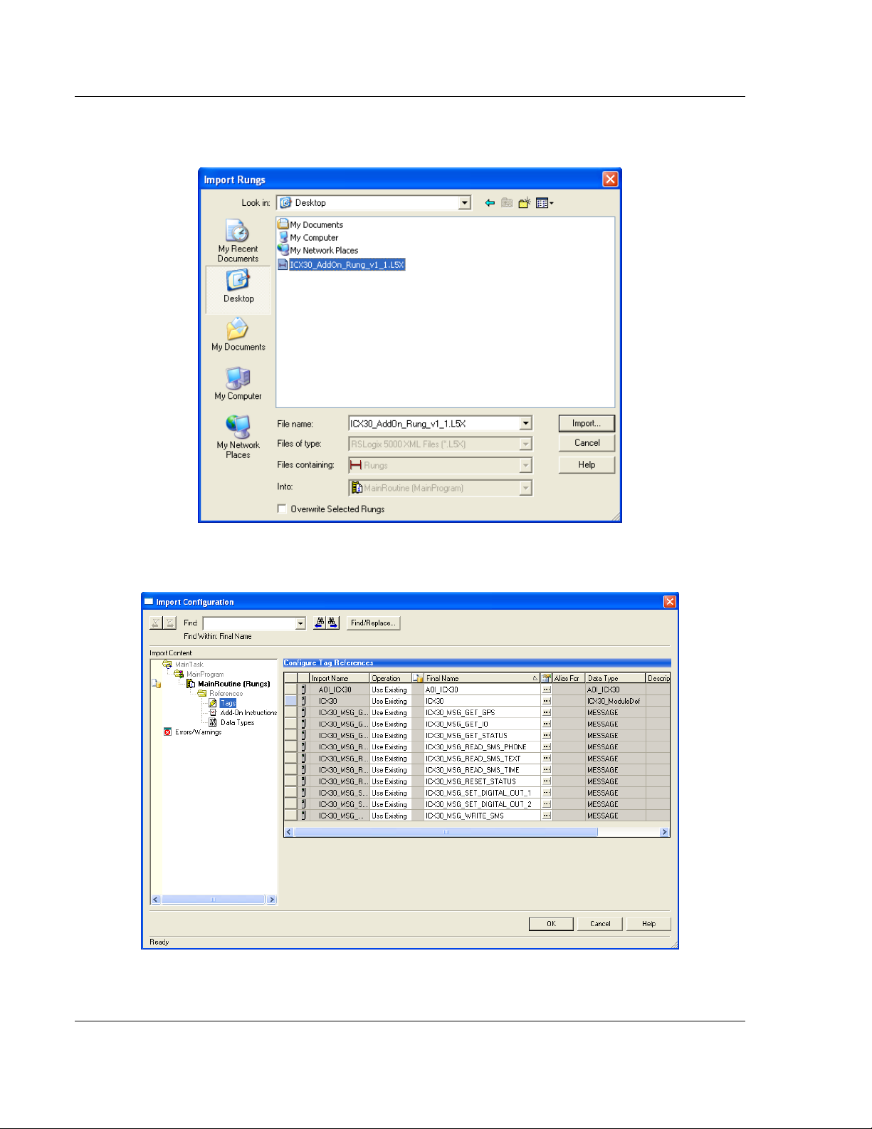
3 Select an empty rung in the routine, and click the right mouse button to open
a shortcut menu. On the shortcut menu, choose IMPORT RUNGS...
ProSoft Technology, Inc. Page 53 of 64
June 22, 2015
Page 54
Ethernet/IP Support ICX30-HWC ♦ Industrial Cellular Gateway
User Manual 3G Cellular (M2M)
4 Navigate to the location on your PC where you saved the Add-On Instruction
(for example, Desktop). Select the .L5X file and click IMPORT.
5 This action opens the Import Configuration dialog box, showing the controller
tags that will be created.
Page 54 of 64 ProSoft Technology, Inc.
June 22, 2015
Page 55

ICX30-HWC ♦ Industrial Cellular Gateway Ethernet/IP Support
3G Cellular (M2M) User Manual
6 Click OK to confirm the import. RSLogix will indicate that the import is in
progress:
7 When the import is completed, the new rung with the Add-On Instruction will
be visible as shown in the following illustration.
8 The procedure has also imported new User Defined Data Types, Controller
Tags, and the Add-On instruction for your project.
9 Save the project. When ready, download the project to the processor.
ProSoft Technology, Inc. Page 55 of 64
June 22, 2015
Page 56

Ethernet/IP Support ICX30-HWC ♦ Industrial Cellular Gateway
ICX30.CONTROL.
Value
Description
Get_Status
0 or 1
Reads status data from the ICX30-HWC. This data will
populate in the ICX30.STATUS tag array.
Reset_Status
0 or 1
Resets status counters in the ICX30.STATUS tag array.
Write_SMS
0 or 1
Sends SMS message from the ICX30-HWC to the
target device(s). Maximum 160 characters.
Read_SMS
0 or 1
Reads SMS message being sent to the ICX30-HWC
from remote device. Maximum 160 characters.
Get_Digital_Analog_Input
0 or 1
Reads Digital/Analog Input values from the ICX30HWC.
Set_Digital_Output_1
0 or 1
Sets digital output 1.
Set_Digital_Output_2
0 or 1
Sets digital output 2.
Get_GPS
0 or 1
Reads GPS data from the ICX30-HWC.
User Manual 3G Cellular (M2M)
6.3 ICX30-HWC Controller Tags
Controller Tags are used to monitor and control elements of the ICX30-HWC
from RSLogix 5000. You will only use the ICX30.xxx controller tag structure.
6.3.1 ICX30.CONTROL
This array contains trigger bits used to request functions from the ICX30-HWC.
After execution, the bit will automatically reset to '0', ready for the next execution.
Page 56 of 64 ProSoft Technology, Inc.
June 22, 2015
Page 57

ICX30-HWC ♦ Industrial Cellular Gateway Ethernet/IP Support
ICX30.SMS.READ.
Value
Description
DateTime
ASCII String
Date and time of received SMS text message.
Phone_Number
ASCII String
Phone number of sender including country and area
code prefixes. (Ex: 16617165100)
Text_Str
ASCII String
Received message text - Maximum 160 characters.
ICX30.SMS.WRITE.
Value
Description
Message_Byte_Count
1 to 160
Number of characters in the message.
Message
ASCII String
Text of message to be sent - Maximum 160 characters.
Phone_Count
1 to 5
Quantity of phone numbers to send to.
Ph_Number_X
ASCII String
Phone number target device including country and area
code prefixes (Ex: 16617165100). Up to 5 phone
numbers.
3G Cellular (M2M) User Manual
6.3.2 ICX30.STATUS
This array is populated when the ICX30.CONTROL.Get_Status tag is triggered.
A partial list of the data includes:
Signal strength
MAC ID and IP Address
Digital and Analog port data
WAN and LAN data usage
3G network and SMS text data usage
Uptime
Temperature
Firmware version
Please see each tag in the ICX30.STATUS array for its corresponding definition.
6.3.3 ICX30.SMS
This array contains the SMS text data for sending and receiving text messages.
The ICX30.SMS.READ array contains the SMS text message data received by
the ICX30-HWC. If the ICX30-HWC receives a new SMS text message, the
ICX30.STATUS.SMS_MSGs_Received tag will increment by one. This tag
refreshes by triggering the ICX30.CONTROL.Read_SMS tag.
The data in this array is overwritten on every re-trigger of the
ICX30.CONTROL.Read_SMS tag.
The ICX30.SMS.WRITE array contains the SMS text message data to send to
multiple SMS text devices. This array must be populated before sending the
message by triggering the ICX30.CONTROL.Write_SMS tag.
ProSoft Technology, Inc. Page 57 of 64
June 22, 2015
Page 58

Ethernet/IP Support ICX30-HWC ♦ Industrial Cellular Gateway
ICX30.IO.
Value
Description
Analog_1
0 to 32767
Analog input 1 raw value
Analog_2
0 to 32767
Analog input 2 raw value
Digital_1
0 or 1
Digital input 1 raw value (when output 1=no current,
0=current flow)
Digital_2
0 or 1
Digital input 2 raw value (when output 1=no current,
0=current flow)
ICX30.GPS.
Value
Description
UTC_Time
Real
UTC Time in HHMMSS.x format. H=hour, M=minute,
S=second
Latitude
Real
Latitude in dddmm.mmmm format, d=degrees,
m=minutes
Longitude
Real
Longitude in dddmm.mmmm format, d= degrees,
m=minutes
Horiz_Dilution
Real
Horizontal Dilution of precision.
Altitude
Real
Altitude in meters above sea level.
GEOID_Height
SINT
Geoid Height in meters.
Last_Update_Interval
SINT
Time since last update.
Fix_Quality
SINT
GPS signal quality.
0 = Invalid
1 = Ideal
1 to 2 = Excellent
2 to 4 = Good
4 to 8 = Moderate
Satellite_Num
SINT
Number of Satellites in range.
User Manual 3G Cellular (M2M)
6.3.4 ICX30.IO
This array contains the Analog and Digital input values of the ICX30-HWC. This
array is updated by triggering the ICX30.CONTROL.Get_Digital_Analog_Input
tag.
Caution: The data in this array is overwritten on every re-trigger of the
ICX30.CONTROL.Get_Digital_Analog_Input tag.
6.3.5 ICX30.GPS
This array contains the current ICX30-HWC GPS data. This array is updated by
triggering the ICX30.CONTROL.Get_GPS tag.
Caution: The data in this array is overwritten on every re-trigger of the
ICX30.CONTROL.Get_GPS tag.
Page 58 of 64 ProSoft Technology, Inc.
June 22, 2015
Page 59
ICX30-HWC ♦ Industrial Cellular Gateway Ethernet/IP Support
3G Cellular (M2M) User Manual
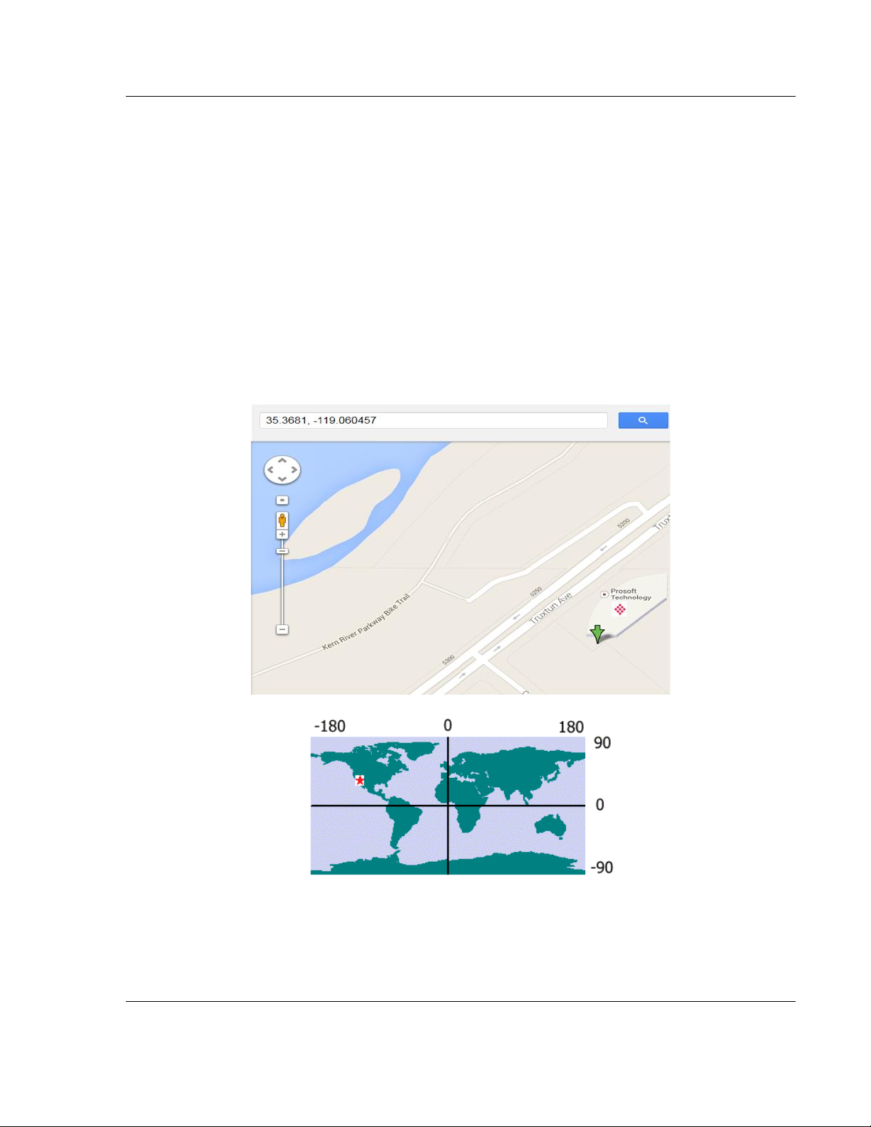
Converting latitude and longitude coordinates to decimal degrees:
The latitude and longitude values are both displayed in the following format:
dddmm.mmmm where d = degrees and m = minutes
To convert the number of minutes to a decimal value, use the following formula:
Decimal value = Minutes / 60
Example:
ProSoft Technology Headquarters: Bakersfield, California, USA
Latitude: 3522.086288,N
Longitude: 11903.627399,W
Latitude decimal degrees: 35 + (22.086288 / 60) = 35.36810
Longitude decimal degrees: 119 + (3.627399 / 60) = -119.06046
6.3.6 ICX30.UTIL
The ICX30.UTIL tag array does not need to be edited.
ProSoft Technology, Inc. Page 59 of 64
June 22, 2015
Page 60

ICX30-HWC ♦ Industrial Cellular Gateway
User Manual 3G Cellular (M2M)
Page 60 of 64 ProSoft Technology, Inc.
June 22, 2015
Page 61

ICX30-HWC ♦ Industrial Cellular Gateway Support, Service & Warranty
In This Chapter
Contacting Technical Support ............................................................... 61
Warranty Information ............................................................................. 62
3G Cellular (M2M) User Manual
7 Support, Service & Warranty
7.1 Contacting Technical Support
ProSoft Technology, Inc. is committed to providing the most efficient and
effective support possible. Before calling, please gather the following information
to assist in expediting this process:
1 Product Version Number
2 System architecture
3 Network details
If the issue is hardware related, we will also need information regarding:
1 Module configuration and associated ladder files, if any
2 Module operation and any unusual behavior
3 Configuration/Debug status information
4 LED patterns
5 Details about the serial, Ethernet or Fieldbus devices interfaced to the
module, if any.
Note: For technical support calls within the United States, an emergency after-hours answering
system allows 24-hour/7-days-a-week pager access to one of our qualified Technical and/or
Application Support Engineers. Detailed contact information for all our worldwide locations is
available on the following page.
ProSoft Technology, Inc. Page 61 of 64
June 22, 2015
Page 62

Support, Service & Warranty ICX30-HWC ♦ Industrial Cellular Gateway
Internet
Web Site: www.prosoft-technology.com/support
E-mail address: support@prosoft-technology.com
Asia Pacific
(location in Malaysia)
Tel: +603.7724.2080
E-mail: asiapc@prosoft-technology.com
Languages spoken include: Chinese, English
Asia Pacific
(location in China)
Tel: +86.21.5187.7337 x888
E-mail: asiapc@prosoft-technology.com
Languages spoken include: Chinese, English
Europe
(location in Toulouse,
France)
Tel: +33 (0) 5.34.36.87.20
E-mail: support.EMEA@prosoft-technology.com
Languages spoken include: French, English
Europe
(location in Dubai, UAE)
Tel: +971-4-214-6911
E-mail: mea@prosoft-technology.com
Languages spoken include: English, Hindi
North America
(location in California)
Tel: +1.661.716.5100
E-mail: support@prosoft-technology.com
Languages spoken include: English, Spanish
Latin America
(Oficina Regional)
Tel: +1-281-2989109
E-Mail: latinam@prosoft-technology.com
Languages spoken include: Spanish, English
Latin America
(location in Puebla, Mexico)
Tel: +52-222-3-99-6565
E-mail: soporte@prosoft-technology.com
Languages spoken include: Spanish
Brasil
(location in Sao Paulo)
Tel: +55-11-5083-3776
E-mail: brasil@prosoft-technology.com
Languages spoken include: Portuguese, English
User Manual 3G Cellular (M2M)
7.2 Warranty Information
For complete details regarding ProSoft Technology’s TERMS & CONDITIONS
OF SALE, WARRANTY, SUPPORT, SERVICE AND RETURN MATERIAL
AUTHORIZATION INSTRUCTIONS please see the documents on the ProSoft
Solutions DVD or go to www.prosoft-technology/warranty.
Documentation is subject to change without notice.
Page 62 of 64 ProSoft Technology, Inc.
June 22, 2015
Page 63

ICX30-HWC ♦ Industrial Cellular Gateway Support, Service & Warranty
3G Cellular (M2M) User Manual
H
Hardware Installation • 37
Index
HSDPA • 43
HSUPA • 43
I
1
1x • 45
A
About the ICX30-HWC Industrial Cellular Gateway • 7
Adding a 1756-ENBT to the Project • 48
Administrator • 35
Advanced Setup • 27
Analog Input • 34
Antenna Installation • 37
Assigning an IP Address to the ICX30-HWC • 15
B
Backup • 36
C
CDMA Communication (Verizon®) • 45
Configuration Webpage • 13, 21
Configuration Webpage Setup • 14
Connecting the Radio to a Network Device • 38
Connecting to your Cellular Provider • 17
Contacting Technical Support • 61
Content Disclaimer • 2
Creating a New RSLogix 5000 Project • 47
D
Digital I/O • 34
Dynamic DNS • 28
E
EDGE • 44
Electrical Specification of I/O Terminals • 39
Ethernet Bridge Network Setup • 50
Ethernet Cable Configuration • 40
Ethernet Cable Specifications • 40
Ethernet/IP Support • 47
EV-DO • 45
F
Firmware Update • 36
G
General • 36
GPRS • 44
GRE Tunnel • 32
GSM Communication (AT&T®) • 43
I/O Terminal • 38
ICX30.CONTROL • 56
ICX30.GPS • 58
ICX30.IO • 58
ICX30.SMS • 57
ICX30.STATUS • 57
ICX30.UTIL • 59
ICX30-HWC Controller Tags • 56
Important Notice • 4
Important Safety Information • 3
Importing the AOI • 53
L
LAN Configuration • 26
LED Indicators • 42
Limitation of Liability • 4
Logs • 36
M
MAC Filtering • 28
N
Network Interface • 24
NTP • 35
P
Package Contents • 10
Password • 35
Ping • 36
Pinouts • 10, 40
Port Forward • 28
Power Requirements • 11
S
Security • 46
Serial Port • 29
Serial Port Basics • 41
SNMP • 28
Specifications • 9
Start Here • 7
Status • 22
Steps of a connection using CDMA (where applicable):
• 20
Steps of a connection using GSM/GPRS • 17
Support, Service & Warranty • 61
System Requirements • 10
U
UMTS • 44
ProSoft Technology, Inc. Page 63 of 64
June 22, 2015
Page 64

Support, Service & Warranty ICX30-HWC ♦ Industrial Cellular Gateway
User Manual 3G Cellular (M2M)
V
VPN Tunnel (IPSEC) • 31
VPN Tunnel (Open VPN) • 31
W
WAN Configuration • 24
Warranty Information • 62
Y
Your Feedback Please • 2
Page 64 of 64 ProSoft Technology, Inc.
June 22, 2015
 Loading...